

Page 1

Installation Guide
C3-Series
Access Control Panels
&
ZKAccess 5.2 software
ZKAccess.com
Page 2
2
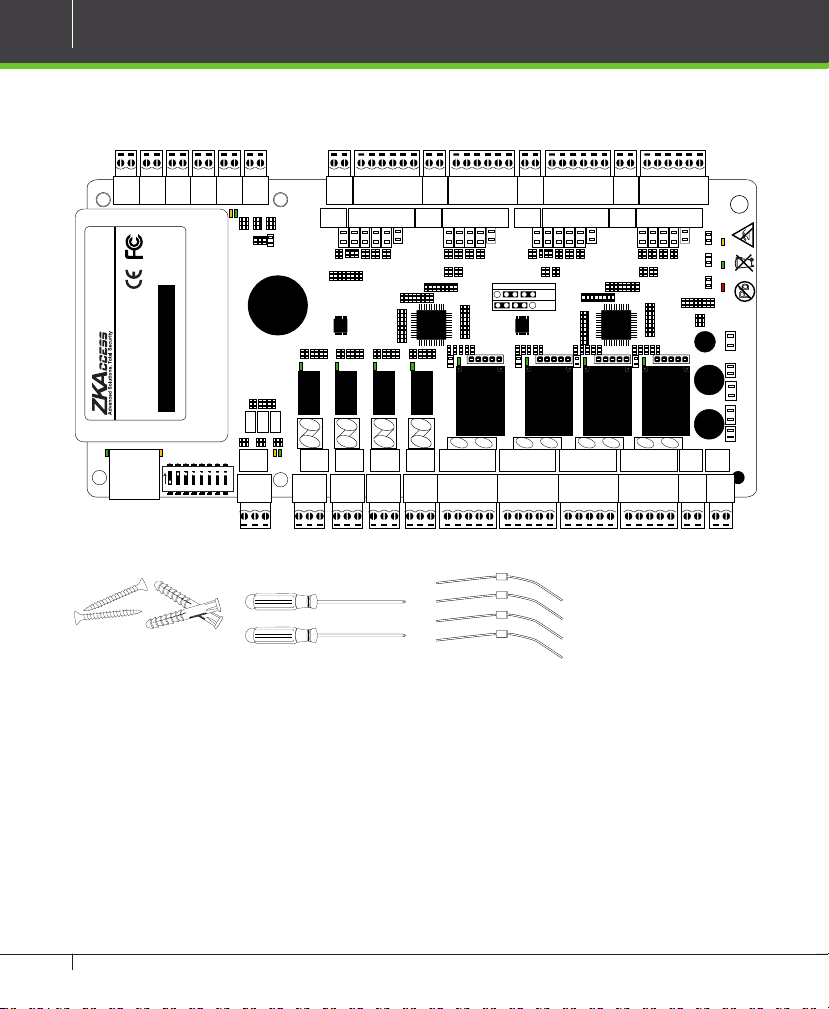
What’s in the Box
AUX 1
AUX 2 AUX 3 AUX 4 EXT EXT
IN
GNDINGNDINGNDINGND
+12V
GND
485-
485+
TX
RX
BUTTON READER
IN
GND
BEEP
GLED
WD1
WD0
BUTTON READER
GND
+12V
IN
GND
GLED
WD1
WD0
BUTTON READER
GND
+12V
IN
GND
BEEP
BEEP
GLED
WD1
WD0
BUTTON READER
GND
+12V
IN
GND
BEEP
GLED
WD1
WD0
GND
+12V
BUTTON BUTTONREADER 1 READER 2BUTTON BUTTONREADER 1 READER 2
+
RUN CARD
+
POWER
+
LINK
ACT
ON
12345678
TX
RX
485+
485--
GND
PC AUXOUT1
NO
COM
NC
NO
COM
NC
NO
COM
NC
NO
COM
AUXOUT3
AUXOUT4
NC
AUXOUT2
C3-Series Access Control Panels & ZKAccess 5.2 software INSTALLATION GUIDE
V+V-12V
SEN
GNDNOCOM
NC
SEN
GNDNOCOM
NC
SEN
GNDNOCOM
NC
SEN
LOCK1
LOCK2
LOCK3
GNDNOCOM
LOCK4 LOCK POWER
GND
NC
4 Diode2 Screws & Anchors 2 Screwdriver
Page 3
CONTENT
What’s in the Box ..................................................................... 2
Optional accessories ............................................................. 4
Safety Precautions...................................................................5
Product PIN Diagram ............................................................ 6
LED Indicators ............................................................................ 7
Product Dimension ................................................................ 8
Installation of Panel & Cabinet ...................................... 9
Wiring Legend ........................................................................ 10
Power Wiring Diagram .................................................... 11
Without Backup Battery .......................................................... 11
With Backup Battery ................................................................ 11
Wiegand Connection ........................................................ 12
REX Connections .................................................................. 13
Lock Connection .................................................................. 14
Normally Open Lock Powered From Lock Terminal ....... 14
Normally Closed Lock Powered From Lock Terminal ..... 14
Switching Wet Contact to Dry Contact .............................. 15
Connecting a lock with external power supply .............. 16
Aux. I/O connection .......................................................... 17
Aux. Input Connection ............................................................ 17
Aux. Output Connection ........................................................ 17
Ethernet Connection ........................................................ 18
LAN Connection ....................................................................... 18
Direct connection..................................................................... 18
RS485 Connection .............................................................. 19
Restore factory setting ............................................................ 20
DIP Switch Setting ............................................................... 21
RS485 Address ........................................................................... 21
Terminal Resistance.................................................................. 21
Typical Installation ............................................................... 22
Troubleshooting ...................................................................23
PC 485 Setting Table .......................................................... 24
Electrical Specifications .................................................. 26
Specifications ......................................................................... 27
3
ZKAccess 5.2
software
Installation and Setup
starts at page 28
C3-Series Access Control Panels & ZKAccess 5.2 software INSTALLATION GUIDE
Page 4
4
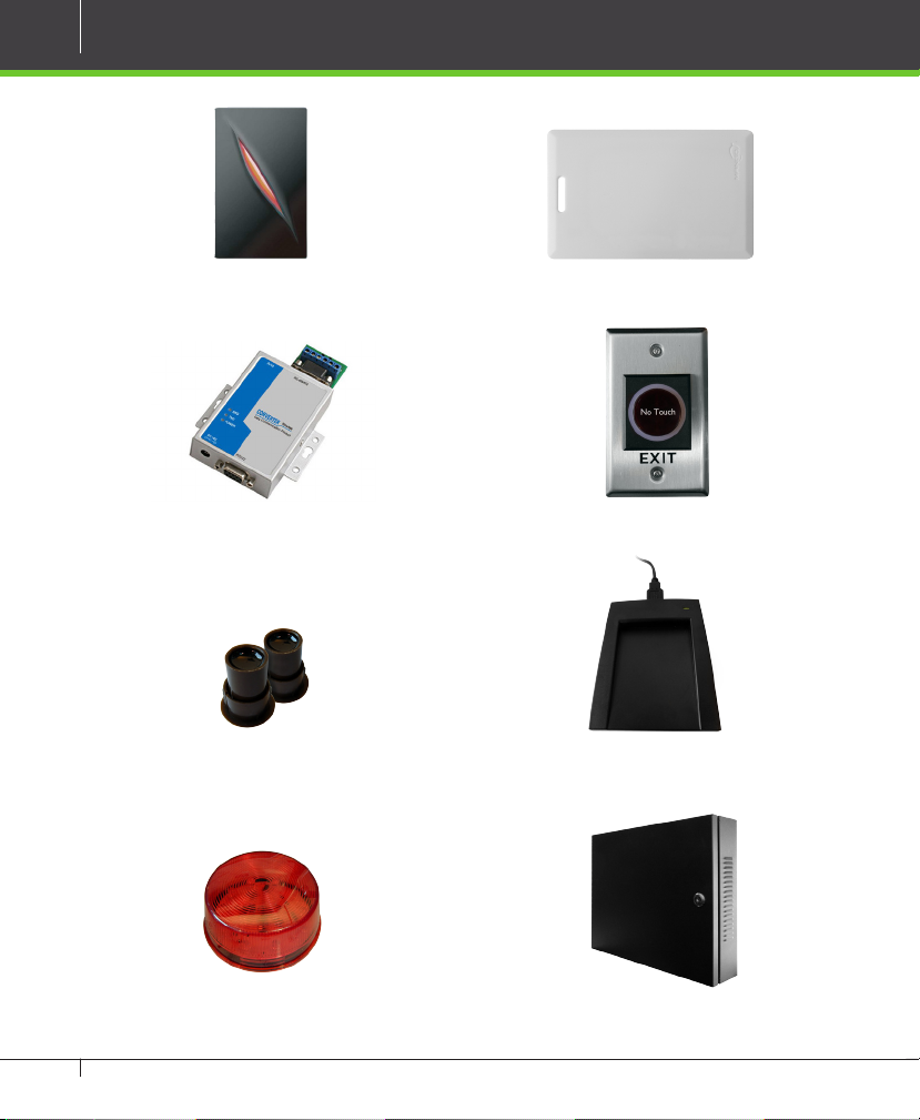
Optional accessories
Wiegand Card Reader Prox Card
RS485 Convertor K1-1 Exit Button
Door Sensor Card Enroller
Alarm C3 Cabinet
C3-Series Access Control Panels & ZKAccess 5.2 software INSTALLATION GUIDE
Page 5
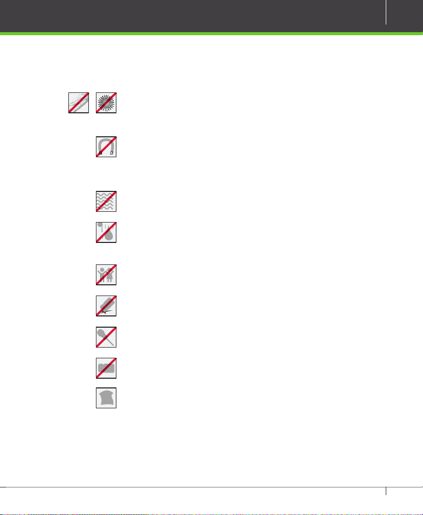
Safety Precautions
The following precautions are to keep user’s safe and prevent any damage.
Please read carefully before installation
Do not install the device in a place subject to direct sun light,
humidity, dust or soot
Do not place a magnet near the product. Magnetic objects
such as magnet, CRT, TV, monitor or speaker may damage the
device.
Do not place the device next to heating equipment
Be careful not to let liquid like water, drinks or chemicals
leak inside the device.
Do not let children touch the device without supervision
Do not drop or damage the device
5
Do not disassemble, repair or alter the device.
Do not use the device for any other purpose than specied.
Clean the device often to remove dust on it. In cleaning, do
not splash water on the device but wipe it out with smooth
cloth or towel.
Contact your supplier in case of a problem.
C3-Series Access Control Panels & ZKAccess 5.2 software INSTALLATION GUIDE
Page 6
6
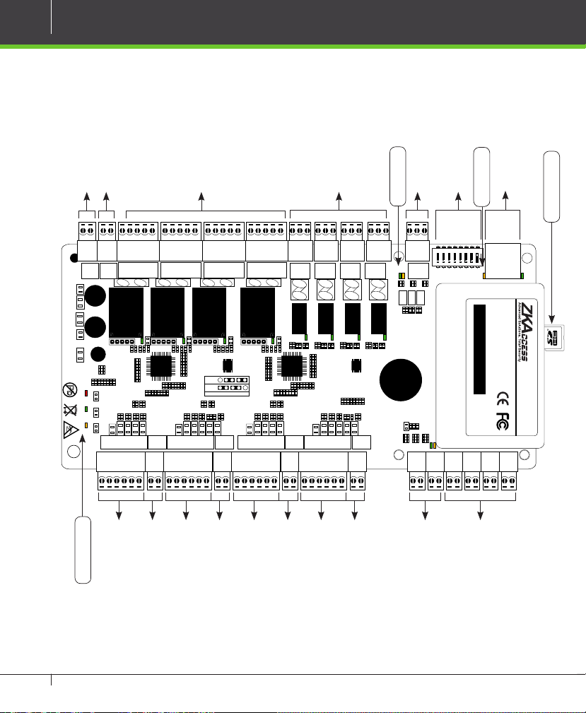
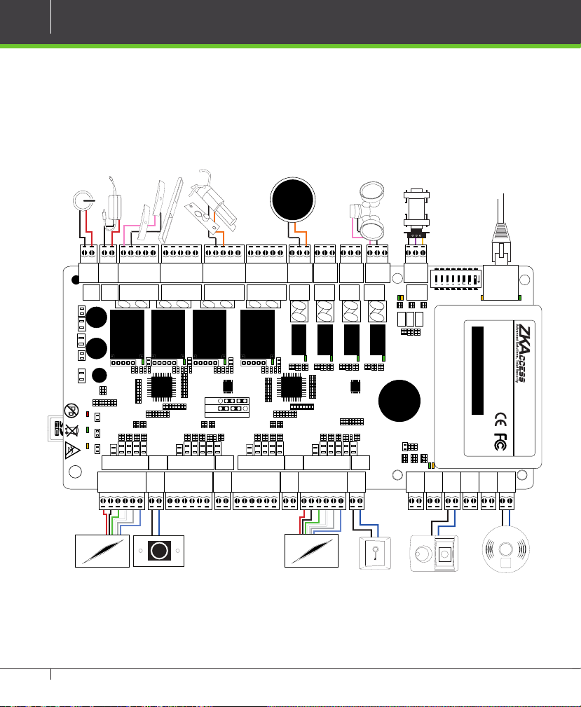
Product PIN Diagram
485 LED
NO
COM
GND
TX
RX
485+
RS485 Communication
DIP Switches
ACT LED
PC AUXOUT1
485+
485--
TX
RX
GND
485-
12345678
ON
ACT
+12V
Ethernet Port
SD Card Slot
LINK
IN
GNDINGNDINGNDINGND
AUX 1
AUX 2 AUX 3 AUX 4 EXT EXT
4 Lock & Door Sensor
NC
NO
COM
+12V
BUTTON READER
AUXOUT4
COM
NC
WD1
WD0
GND
4 Aux Output
AUXOUT2
AUXOUT3
NC
NO
COM
NC
NO
IN
GND
BEEP
GLED
BUTTON READER
Lock Power
C3 Power
GND
+
POWER
+
RUN CARD
+
+12V
GNDNOCOM
NC
BEEP
GLED
WD1
WD0
GND
LOCK4 LOCK POWER
V+V-12V
LOCK3
GNDNOCOM
NC
SEN
WD0
GND
+12V
IN
GND
BUTTON READER
LOCK2
GNDNOCOM
NC
SEN
IN
GND
BEEP
GLED
WD1
BUTTON READER
LOCK1
GNDNOCOM
NC
SEN
BUTTON BUTTONREADER 1 READER 2BUTTON BUTTONREADER 1 READER 2
BEEP
GLED
WD1
WD0
GND
+12V
SEN
IN
GND
#2 Door Exit Button
#2 Door Card Reader
#3 Door Exit Button
#3 Door Card Reader
#4 Door Exit Button
#4 Door Card Reader
Status LED
Figure 1
C3-Series Access Control Panels & ZKAccess 5.2 software INSTALLATION GUIDE
#1 Door Card Reader
#1 Door Exit Button
Reserved
4 Aux Inputs
Page 7
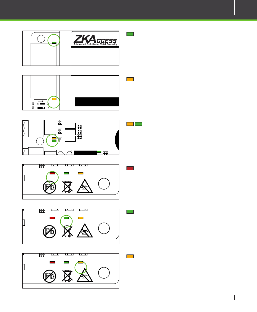
LED Indicators
LINK
AUX 1
IN
GND
IN
GND
IN
AUX 2 AUX 3 AUX 4 EXT EXT
12345678
TX
RX
ACT
LINK
AUX 1
IN
GND
IN
GND
IN
GND
IN
GND
+12V
GND
485-
485+
AUX 2 AUX 3 AUX 4 EXT EXT
AUXOUT1
12345678
ON
AUX 1
IN
GND
IN
AUX 2 AUX 3 AUX 4 EXT EXT
+
+
BUTTON BUTTONREADER 1 READER 2BUTTON BUTTONREADER 1 READER 2
IN
GND
BEEP
GLED
WD1
WD0
GND
+12V
BUTTON READER
IN
GND
BEEP
GLED
WD1
WD0
GND
+12V
BUTTON READER
IN
GND
BEEP
GLED
WD1
WD0
GND
+12V
BUTTON READER
IN
GND
BEEP
GLED
WD1
WD0
GND
+12V
BUTTON READER
+
+
BUTTON BUTTONREADER 1 READER 2BUTTON BUTTONREADER 1 READER 2
IN
GND
BEEP
GLED
WD1
WD0
GND
+12V
BUTTON READER
IN
GND
BEEP
GLED
WD1
WD0
GND
+12V
BUTTON READER
IN
GND
BEEP
GLED
WD1
WD0
GND
+12V
BUTTON READER
IN
GND
BEEP
GLED
WD1
WD0
GND
+12V
BUTTON READER
+
+
BUTTON BUTTONREADER 1 READER 2BUTTON BUTTONREADER 1 READER 2
IN
GND
BEEP
GLED
WD1
WD0
GND
+12V
BUTTON READER
IN
GND
BEEP
GLED
WD1
WD0
GND
+12V
BUTTON READER
IN
GND
BEEP
GLED
WD1
WD0
GND
+12V
BUTTON READER
IN
GND
BEEP
GLED
WD1
WD0
GND
+12V
BUTTON READER
7
PC
+
+
+
485+
485--
GND
NO
LINK
Figure 2
ON
ACT
Figure 3
TX
RX
Figure 4
POWER
RUN CARD
Figure 5
POWER
RUN CARD
Figure 6
POWER
RUN CARD
Figure 7
LINK Solid Green LED indicates TCP/IP
communication is normal
Flashing (ACT )Yellow LED indicates
data communication is in progress
PC RS485 (TX/RX) Flashing Yellow
& Green LED indicates communication is
in progress
Flashing (POWER) Red LED indicates
the panel is powered on
Flashing (RUN) Green LED indicated
that panel is in normal working state
Flashing (CARD) Yellow LED indicates
that the card is read by the panel
C3-Series Access Control Panels & ZKAccess 5.2 software INSTALLATION GUIDE
Page 8
8
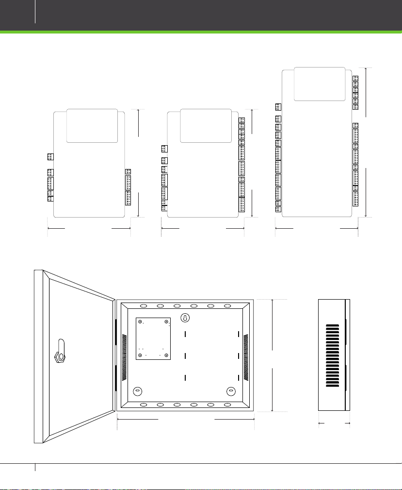
Product Dimension
C3-100 C3-200 C3-400
8.00in (203.2mm)
6.325 in (160.6mm)
4.17in (106mm)
4.17in (106mm)
Figure 8
C3- Metal Cabinet
13.625in (330.2mm)
Figure 9
C3-Series Access Control Panels & ZKAccess 5.2 software INSTALLATION GUIDE
6.325 in (160.6mm)
4.17in (106mm)
11.75in
(279.4 mm)
3.56in
(90.5mm)
Page 9
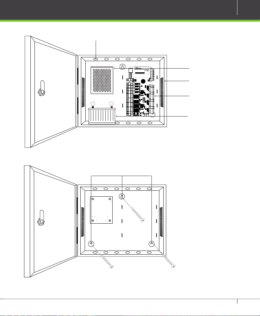
Installation of Panel & Cabinet
+--
Cable Conduit
(Punch Hole for cables)
9
ON
12345678
485+
PC AUXOUT1
485--
GND
NO
COM
NC
AUXOUT2
NO
COM
NC
AUXOUT3
NO
COM
NC
AUXOUT4
NO
COM
NC
SEN
GND
LOCK1
NO
COM
NC
SEN
GND
LOCK2
NO
COM
NC
SEN
GND
LOCK3
NO
COM
NC
SEN
GND
LOCK4 LOCK POWER
NO
COM
NC
V+
V-
12V
GND
Figure 10
Mounting Holes
LINK
ACT
TX
RX
AUX 1
IN
GND
AUX 2 AUX 3 AUX 4 EXT EXT
IN
GND
IN
GND
IN
GND
+12V
TX
GND
RX
485485+
BUTTON READER
IN
GND
BEEP
GLED
WD1
WD0
GND
+12V
BUTTON READER
IN
GND
BEEP
GLED
WD1
WD0
GND
+12V
BUTTON BUTTONREADER 1 READER 2BUTTON BUTTONREADER 1 READER 2
BUTTON READER
IN
GND
BEEP
GLED
WD1
WD0
GND
+12V
BUTTON READER
IN
GND
BEEP
GLED
WD1
WD0
GND
+12V
+
+
+
POWER
RUN C ARD
Power Supply
Heat Dissipation Grill
C3- Panel
Backup Battery
Figure 11
We recommend drilling the mounting plate screws into solid wood (i.e. stud/beam). If a stud/beam cannot be found, then use
the supplied drywall plastic mollies (anchors).
C3-Series Access Control Panels & ZKAccess 5.2 software INSTALLATION GUIDE
Page 10
10
Wiring Legend
12V DC Power
GND
+
POWER
RUN CARD
12V DC Power Supply
V+V-12V
NC
+
+
WD0
GND
+12V
Normally Close Lock
Normally Open Lock
485 Convertor
Ethernet Cable
Floodlight
ALARM
RS485
LOCK3
LOCK4 LOCK POWER
GNDNOCOM
NC
SEN
GNDNOCOM
LOCK2
GNDNOCOM
NC
SEN
LOCK1
SEN
GNDNOCOM
NC
SEN
NO
COM
NC
NO
COM
NC
COM
NC
NO
COM
NC
AUXOUT2
AUXOUT3
AUXOUT4
BUTTON BUTTONREADER 1 READER 2BUTTON BUTTONREADER 1 READER 2
IN
GND
BEEP
GLED
WD1
WD0
GND
+12V
IN
GND
BEEP
GLED
WD1
WD0
GND
+12V
IN
GND
BEEP
GLED
WD1
WD0
GND
+12V
IN
GND
BEEP
GLED
WD1
BUTTON READER
BUTTON READER
BUTTON READER
BUTTON READER
PC AUXOUT1
NO
485+
485--
GND
TX
RX
TX
RX
GND
485-
485+
12345678
ON
ACT
+12V
LINK
IN
GNDINGNDINGNDINGND
AUX 1
AUX 2 AUX 3 AUX 4 EXT EXT
No Touch
EXIT
Card Reader
Exit Button
Card Reader
Figure 12
C3-Series Access Control Panels & ZKAccess 5.2 software INSTALLATION GUIDE
P
Y
U
L
S
K
H
E
E
T
O
W
T
T
E
S
S
E
T
T
W
O
T
E
E
H
K
S
L
U
Y
P
Detector
ALARM
FIRE
PUSH
Exit Button
IR Sensor
Page 11
+
+
+
POWER
RUN CARD
V+
V-
12V
GND
GND
+12V
+
+
+
POWER
RUN CARD
V+
V-
12V
GND
GND
+12V
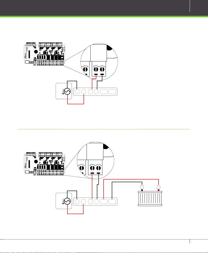
Power Wiring Diagram
AUX 1
AUX 2 AUX 3 AUX 4 EXT EXT
BUTTON READER
BUTTON READER
BUTTON READER
BUTTON READER
GLED
WD1
WD0
GND
+12V
IN
GND
BEEP
GLED
WD1
WD0
GND
+12V
IN
GND
BEEP
GLED
WD1
WD0
GND
+12V
IN
GND
BEEP
GLED
WD1
WD0
GND
+12V
BUTTON BUTTONREADER 1 READER 2BUTTON BUTTONREADER 1 READER 2
+
RUN CARD
+
POWER
+
NO
COM
NC
NO
COM
NC
AUXOUT3
AUXOUT4
V+V-12V
SEN
GNDNOCOM
LOCK1
GND
NC
SEN
GNDNOCOM
NC
SEN
GNDNOCOM
NC
SEN
GNDNOCOM
NC
LOCK2
LOCK3
LOCK4 LOCK POWER
24V AC
AC
IN
GNDINGNDINGNDINGND
+12V
GND
485-
485+
IN
GND
BEEP
TX
RX
ACT
LINK
TX
RX
ON
12345678
NO
COMNC485+
485--
GND
NO
COM
NC
PC AUXOUT1
AUXOUT2
Without Backup Battery
N L + - BT+ BT
-
Switching Power Supply
11
Ground
Figure 13
AUX 1
AUX 2 AUX 3 AUX 4 EXT EXT
BUTTON READER
BUTTON READER
BUTTON READER
IN
GNDINGNDINGNDINGND
+12V
GND
485-
485+
IN
GND
BEEP
TX
RX
ACT
LINK
TX
RX
ON
12345678
NO
COMNC485+
485--
GND
NO
COM
NC
PC AUXOUT1
AUXOUT2
BUTTON READER
GLED
WD1
WD0
GND
+12V
IN
GND
BEEP
GLED
WD1
WD0
GND
+12V
IN
GND
BEEP
GLED
WD1
WD0
GND
+12V
IN
GND
BEEP
GLED
WD1
BUTTON BUTTONREADER 1 READER 2BUTTON BUTTONREADER 1 READER 2
NO
COM
NC
NO
COM
NC
SEN
GNDNOCOM
NC
SEN
GNDNOCOM
NC
SEN
GNDNOCOM
NC
SEN
GNDNOCOM
AUXOUT3
AUXOUT4
NC
LOCK1
LOCK2
LOCK3
LOCK4 LOCK POWER
With Backup Battery
WD0
GND
+12V
+
RUN CARD
+
POWER
+
V+V-12V
GND
+--
24V AC
AC
N L + - BT+ BT
Ground
C3-Series Access Control Panels & ZKAccess 5.2 software INSTALLATION GUIDE
-
Switching Power Supply
Figure 14
Page 12
12
TX
RX
TX
ACT
LINK
RX
AUX 1
IN
GND
IN
GND
IN
GND
IN
GND
+12V
GND
485-
485+
AUX 2 AUX 3 AUX 4 EXT EXT
IN
GND
BEEP
GLED
WD1
WD0
GND
+12V
BUTTON READER
IN
BUTTON READER
NO
COM
NC
485+
485--
GND
PC AUXOUT1
NO
COM
NC
AUXOUT2
NO
COM
NC
AUXOUT3
NO
COM
NC
AUXOUT4
12345678
ON
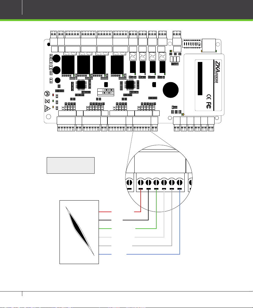
Wiegand Connection
GND
GNDNOCOM
NC
SEN
GNDNOCOM
NC
SEN
NC
NC
SEN
GNDNOCOM
LOCK4 LOCK POWER
V+V-12V
GNDNOCOM
NC
NO
COM
NC
SEN
NC
NO
COM
NC
NO
COM
AUXOUT2
AUXOUT3
AUXOUT4
LOCK1
LOCK2
LOCK3
PC AUXOUT1
NO
COM
485+
485--
GND
TX
RX
12345678
ON
ACT
LINK
+
POWER
+
RUN CARD
+
BUTTON BUTTONREADER 1 READER 2BUTTON BUTTONREADER 1 READER 2
485-
+12V
BUTTON READER
BUTTON READER
BUTTON READER
IN
GND
BEEP
GLED
WD1
WD0
GND
+12V
IN
GND
BEEP
GLED
WD1
WD0
GND
+12V
IN
GND
BEEP
GLED
WD1
WD0
GND
+12V
IN
GND
BEEP
GLED
WD1
WD0
GND
485+
BUTTON READER
TX
RX
IN
+12V
GND
GNDINGNDINGNDINGND
AUX 1
AUX 2 AUX 3 AUX 4 EXT EXT
16 or 18 AWG shielded
cable recommended
DC+(6-14V)
GND
Wiegand D0
Wiegand D1
Green LED
Beeper
Wiegand Card Reader
C3-Series Access Control Panels & ZKAccess 5.2 software INSTALLATION GUIDE
Figure 15
Page 13

REX Connections
TX
RX
TX
ACT
LINK
RX
AUX 1
IN
GND
IN
GND
IN
GND
IN
GND
+12V
GND
485-
485+
AUX 2 AUX 3 AUX 4 EXT EXT
IN
GND
BEEP
GLED
BUTTON READER
NO
COM
NC
485+
485--
GND
PC AUXOUT1
NO
COM
NC
AUXOUT2
AUXOUT3
12345678
ON
TX
RX
TX
ACT
RX
IN
GND
IN
GND
IN
GND
+12V
GND
485-
485+
AUX 2 AUX 3 AUX 4 EXT EXT
IN
GND
BEEP
GLED
WD1
WD0
GND
+12V
BUTTON READER
IN
GND
BEEP
GLED
BUTTON READER
NO
COM
NC
485+
485--
GND
PC AUXOUT1
NO
COM
NC
AUXOUT2
NO
COM
NC
AUXOUT3
NO
COM
NC
AUXOUT4
SEN
GND
NO
LOCK1
12345678
ON
13
GND
+
POWER
RUN CARD
ZK ABK Exit Button
+
+
+12V
V+V-12V
GND
WD0
NC
WD1
LOCK4 LOCK POWER
GNDNOCOM
SEN
GNDNOCOM
NC
SEN
GLED
WD1
WD0
GND
+12V
IN
GND
BEEP
GLED
BUTTON READER
NC
GND
BEEP
NC
SEN
GNDNOCOM
BUTTON BUTTONREADER 1 READER 2BUTTON BUTTONREADER 1 READER 2
WD0
GND
+12V
IN
BUTTON READER
NO
COM
NC
SEN
GNDNOCOM
+12V
IN
GND
BEEP
GLED
WD1
BUTTON READER
NO
COM
NC
NO
COM
NC
IN
GND
BEEP
GLED
WD1
WD0
GND
BUTTON READER
AUXOUT2
AUXOUT3
AUXOUT4
LOCK1
LOCK2
LOCK3
PC AUXOUT1
NO
COM
NC
485+
485--
GND
TX
RX
12345678
ON
ACT
TX
RX
+12V
GND
485-
485+
LINK
IN
GNDINGNDINGNDINGND
AUX 1
AUX 2 AUX 3 AUX 4 EXT EXT
NO
GND
COM
BUTTON
PUSH
12V DC ( + )
Separate Power Supply
12V DC ( - )
Unused
No Touch
EXIT
K1-1 Exit Switch
Figure 16
C3-Series Access Control Panels & ZKAccess 5.2 software INSTALLATION GUIDE
Page 14
14
+
+
+
POWER
RUN CARD
V+
V-
12V
GND
NC
SEN
GNDNOCOM
NC
LOCK4 LOCK POWER
IN
GND
BEEP
GLED
WD1
WD0
GND
+12V
BUTTON READER
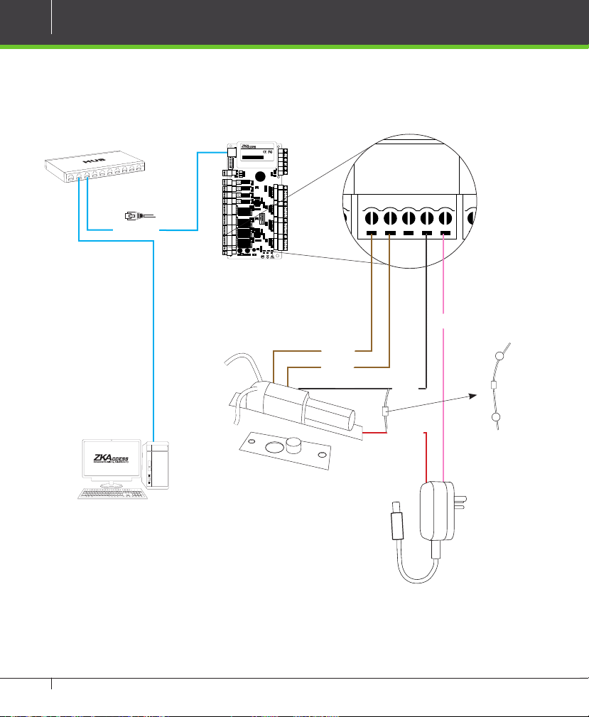
Lock Connection
Connecting a Lock with External Power Supply
ETHERNET
(Dry Contact)
LINK
ON
ACT
12345678
485+
PC AUXOUT1
485--
GND
TX
RX
NO
COM
NC
AUXOUT2
NO
COM
NC
AUXOUT3
NO
COM
NC
AUXOUT4
NO
COM
NC
SEN
GND
LOCK1
NO
COM
NC
SEN
GND
LOCK2
NO
COM
NC
SEN
GND
LOCK3
NO
COM
NC
SEN
GND
LOCK4 LOCK POWER
NO
COM
NC
V+
V-
12V
GND
+
POWER
AUX 1
IN
GND
AUX 2 AUX 3 AUX 4 EXT EXT
IN
GND
IN
GND
IN
GND
+12V
TX
GND
RX
485485+
BUTTON READER
IN
GND
BEEP
GLED
WD1
WD0
GND
+12V
BUTTON READER
IN
GND
BEEP
GLED
WD1
WD0
GND
+12V
BUTTON BUTTONREADER 1 READER 2BUTTON BUTTONREADER 1 READER 2
BUTTON READER
IN
GND
BEEP
GLED
WD1
WD0
GND
+12V
BUTTON READER
IN
GND
BEEP
GLED
WD1
WD0
GND
+12V
+
+
RUN CARD
GND
C3-Series Access Control Panels & ZKAccess 5.2 software INSTALLATION GUIDE
Figure 17
Sensor
Sensor
GND
12V DC
12V DC
-
+
FR107
Diode
Page 15

+
+
+
BUTTON BUTTONREADER 1 READER 2BUTTON BUTTONREADER 1 READER 2
POWER
RUN CARD
GND
BEEP
GLED
WD1
WD0
GND
+12VINGND
BEEP
GLED
WD1
WD0
GND
+12V
BUTTON READER
V-
12V
GND
LOCK POWER
IN
GND
BEEP
GLED
WD1
WD0
GND
+12V
BUTTON READER
+
+
+
BUTTON BUTTONREADER 1 READER 2BUTTON BUTTONREADER 1 READER 2
POWER
RUN CARD
BEEP
GLED
WD1
WD0
GND
+12VINGND
BEEP
GLED
WD1
WD0
GND
+12V
BUTTON READER
IN
GND
BEEP
GLED
WD1
WD0
GND
+12V
BUTTON READER
Switching Dry Contact to Wet Contact
Important Notes:
The factory default jumper setting is set as dry mode. If you want to power the lock from
the panel, you must take the following steps
Select the appropriate lock relay and nd its jumpers
1. Take o the jumpers and change
2. Connect the lock as shown in the diagram, (see gure 20 and 21)
12345
to
12345
15
LINK
ON
ACT
12345678
485+
PC AUXOUT1
485--
GND
TX
RX
NO
COM
NC
AUXOUT2
NO
COM
NC
AUXOUT3
NO
COM
NC
AUXOUT4
NO
COM
NC
SEN
GND
LOCK1
NO
COM
NC
SEN
GND
LOCK2
NO
COM
NC
SEN
GND
LOCK3
NO
COM
NC
SEN
GND
LOCK4 LOCK POWER
NO
COM
NC
V+
V-
12V
GND
C3-Panel Select one Relay
AUX 1
IN
GND
AUX 2 AUX 3 AUX 4 EXT EXT
IN
GND
IN
GND
IN
GND
+12V
TX
GND
RX
485485+
BUTTON READER
IN
GND
BUTTON BUTTONREADER 1 READER 2BUTTON BUTTONREADER 1 READER 2
+
+
+
POWER
RUN CARD
BEEP
GLED
WD1
WD0
GND
+12V
BUTTON READER
IN
GND
BEEP
GLED
WD1
WD0
GND
+12V
BUTTON READER
IN
GND
BEEP
GLED
WD1
WD0
GND
+12V
BUTTON READER
IN
GND
BEEP
GLED
WD1
WD0
GND
+12V
SEN
GNDNOCOM
LOCK1
NC
SEN
GNDNOCOM
NC
SEN
GNDNOCOM
NC
SEN
LOCK2
LOCK3
GNDNOCOM
LOCK4
V+
NC
4 Lock Relays
Figure 18
5 4 3 2 1 5 4 3 2 1 5 4 3 2 1
Default setting
1, 2 - 3, 4
Take o jumpers Jumpers Plug Jumpers
2, 3 - 4, 5
Figure 19
C3-Series Access Control Panels & ZKAccess 5.2 software INSTALLATION GUIDE
Page 16

16
+
+
+
BUTTON BUTTONREADER 1 READER 2BUTTON BUTTONREADER 1 READER 2
POWER
RUN CARD
IN
GND
BEEP
GLED
WD1
WD0
GND
+12VINGND
BEEP
GLED
WD1
WD0
GND
+12V
BUTTON READER
NC
V+V-12V
GND
SEN
GNDNOCOM
NC
LOCK1
SEN
GNDNOCOM
NC
LOCK2
SEN
GNDNOCOM
NC
LOCK3
SEN
GNDNOCOM
NC
LOCK4 LOCK POWER
IN
GND
BEEP
GLED
WD1
WD0
GND
+12V
BUTTON READER
+
+
+
POWER
RUN CARD
V+V-12V
GND
NC
WD1
WD0
GND
+12V
+
+
+
POWER
RUN CARD
V+V-12V
GND
NC
WD1
WD0
GND
+12V
Lock Connection
Normally Open Lock Powered From Lock Terminal
(Wet Contact)
ETHERNET
LINK
ON
ACT
12345678
485+
PC AUXOUT1
485--
GND
TX
RX
NO
COM
NC
AUXOUT2
NO
COM
NC
AUXOUT3
NO
COM
NC
AUXOUT4
NO
COM
NC
SEN
GND
LOCK1
NO
COM
NC
SEN
GND
LOCK2
NO
COM
NC
SEN
GND
LOCK3
NO
COM
NC
SEN
GND
LOCK4 LOCK POWER
NO
COM
NC
V+
V-
12V
GND
AUX 1
IN
GND
AUX 2 AUX 3 AUX 4 EXT EXT
IN
GND
IN
GND
IN
GND
+12V
TX
GND
RX
485485+
BUTTON READER
IN
GND
BEEP
GLED
WD1
WD0
GND
+12V
BUTTON READER
IN
GND
BEEP
GLED
WD1
WD0
GND
+12V
BUTTON BUTTONREADER 1 READER 2BUTTON BUTTONREADER 1 READER 2
BUTTON READER
IN
GND
BEEP
GLED
WD1
WD0
GND
+12V
BUTTON READER
IN
GND
BEEP
GLED
WD1
WD0
GND
+12V
+
+
+
POWER
RUN CARD
12V DC
GND
16 or 18 AWG shielded cable recommended
GND
12V DC
Figure 20
Normally Closed Lock Powered From Lock Terminal
AUX 1
IN
GND
AUX 2 AUX 3 AUX 4 EXT EXT
IN
GND
IN
GND
IN
GND
+12V
GND
485485+
BUTTON READER
IN
GND
BEEP
GLED
WD1
WD0
GND
+12V
BUTTON READER
IN
GND
BEEP
GLED
WD1
WD0
GND
+12V
BUTTON READER
IN
GND
BEEP
GLED
WD1
WD0
GND
+12V
BUTTON READER
IN
GND
BEEP
GLED
WD1
WD0
GND
+12V
12V DC
GND
ETHERNET
(Wet Contact)
LINK
ON
ACT
12345678
485+
PC AUXOUT1
485--
GND
TX
RX
NO
COM
NC
AUXOUT2
NO
COM
NC
AUXOUT3
NO
COM
NC
AUXOUT4
NO
COM
NC
SEN
GND
LOCK1
NO
COM
NC
SEN
GND
LOCK2
NO
COM
NC
SEN
GND
LOCK3
NO
COM
NC
SEN
GND
LOCK4 LOCK POWER
NO
COM
NC
V+
V-
+
12V
GND
+
POWER
RUN CARD
TX
RX
BUTTON BUTTONREADER 1 READER 2BUTTON BUTTONREADER 1 READER 2
+
+
-
FR107
Diode
+
-
C3-Series Access Control Panels & ZKAccess 5.2 software INSTALLATION GUIDE
Figure 21
GND
12V DC
FR107
Diode
Page 17

Aux. I/O connection
+
+
+
BUTTON BUTTONREADER 1 READER 2BUTTON BUTTONREADER 1 READER 2
TX
RX
POWER
RUN CARD
IN
GND
BEEP
GLED
WD1
WD0
GND
+12V
BUTTON READER
IN
GND
BEEP
GLED
WD1
WD0
GND
+12V
BUTTON READER
IN
GND
BEEP
GLED
WD1
WD0
GND
+12V
BUTTON READER
NO
COMNCNO
COM
NC
AUXOUT2
NO
COM
NC
AUXOUT3
NO
COM
NC
V+V-12V
GND
AUXOUT4
SEN
GNDNOCOM
NC
LOCK1
SEN
GNDNOCOM
NC
LOCK2
SEN
GNDNOCOM
NC
LOCK3
SEN
GNDNOCOM
NC
LOCK4 LOCK POWER
IN
GND
BEEP
GLED
WD1
WD0
GND
+12V
BUTTON READER
AUX 1
IN
GND
IN
GND
AUX 2 AUX 3 AUX 4 EXT EXT
Aux. Input Connection
17
ETHERNET
ETHERNET
LINK
ON
ACT
12345678
485+
PC AUXOUT1
485--
GND
TX
RX
NO
COM
NC
AUXOUT2
NO
COM
NC
AUXOUT3
NO
COM
NC
AUXOUT4
NO
COM
NC
SEN
GND
LOCK1
NO
COM
NC
SEN
GND
LOCK2
NO
COM
NC
SEN
GND
LOCK3
NO
COM
NC
SEN
GND
LOCK4 LOCK POWER
NO
COM
NC
V+
V-
12V
GND
AUX 1
IN
GND
AUX 2 AUX 3 AUX 4 EXT EXT
IN
GND
IN
GND
IN
GND
+12V
TX
GND
RX
485485+
BUTTON READER
IN
GND
BEEP
GLED
WD1
WD0
GND
+12V
BUTTON READER
IN
GND
BEEP
GLED
WD1
WD0
GND
+12V
BUTTON BUTTONREADER 1 READER 2BUTTON BUTTONREADER 1 READER 2
BUTTON READER
IN
GND
BEEP
GLED
WD1
WD0
GND
+12V
BUTTON READER
IN
GND
BEEP
GLED
WD1
WD0
GND
+12V
+
+
+
POWER
RUN CARD
Figure 22
Aux. Output Connection
LINK
ON
ACT
12345678
485+
PC AUXOUT1
485--
GND
TX
RX
NO
COM
NC
AUXOUT2
NO
COM
NC
AUXOUT3
NO
COM
NC
AUXOUT4
NO
COM
NC
SEN
GND
LOCK1
NO
COM
NC
SEN
GND
LOCK2
NO
COM
NC
SEN
GND
LOCK3
NO
COM
NC
SEN
GND
LOCK4 LOCK POWER
NO
COM
NC
V+
V-
12V
GND
AUX 1
IN
GND
AUX 2 AUX 3 AUX 4 EXT EXT
IN
GND
IN
GND
IN
GND
+12V
TX
GND
RX
485485+
BUTTON READER
IN
GND
BEEP
GLED
WD1
WD0
GND
+12V
BUTTON READER
IN
GND
BEEP
GLED
WD1
WD0
GND
+12V
BUTTON BUTTONREADER 1 READER 2BUTTON BUTTONREADER 1 READER 2
BUTTON READER
IN
GND
BEEP
GLED
WD1
WD0
GND
+12V
BUTTON READER
IN
GND
BEEP
GLED
WD1
WD0
GND
+12V
+
+
+
POWER
RUN CARD
12V DC
GND
12V DC
S
E
T
O
T
H
S
U
P
Y
L
K
E
E
W
T
E
S
ALARM
T
W
E
E
K
L
Y
FIRE
P
U
S
H
ALARM
T
O
T
GND
12V DC
Figure 23
C3-Series Access Control Panels & ZKAccess 5.2 software INSTALLATION GUIDE
Page 18

18
Ethernet Connection
LAN Connection
Important Notes:
1. Both 10Base-T and 100Base-T are supported.
2. This cable distance must be less than 330 ft. (100m).
3. For cable length of more than 330 ft. (100m). use HUB to amplify the signal.
USB
CR10 Card Issuer
ETHERNET
LINK
ON
ACT
12345678
485+
PC AUXOUT1
485--
GND
TX
RX
NO
COM
NC
AUXOUT2
NO
COM
NC
AUXOUT3
NO
COM
NC
AUXOUT4
NO
COM
NC
SEN
GND
LOCK1
NO
COM
NC
SEN
GND
LOCK2
NO
COM
NC
SEN
GND
LOCK3
NO
COM
NC
SEN
GND
LOCK4 LOCK POWER
NO
COM
NC
V+
V-
12V
GND
AUX 1
IN
GND
AUX 2 AUX 3 AUX 4 EXT EXT
IN
GND
IN
GND
IN
GND
+12V
TX
GND
RX
485485+
BUTTON READER
IN
GND
BEEP
GLED
WD1
WD0
GND
+12V
BUTTON READER
IN
GND
BEEP
GLED
WD1
WD0
GND
+12V
BUTTON BUTTONREADER 1 READER 2BUTTON BUTTONREADER 1 READER 2
BUTTON READER
IN
GND
BEEP
GLED
WD1
WD0
GND
+12V
BUTTON READER
IN
GND
BEEP
GLED
WD1
WD0
GND
+12V
+
+
+
POWER
RUN CARD
CAT5e or CAT6 ethernet
LINK
ON
ACT
12345678
485+
PC AUXOUT1
485--
GND
TX
RX
NO
COM
NC
AUXOUT2
NO
COM
NC
AUXOUT3
NO
COM
NC
AUXOUT4
NO
COM
NC
SEN
GND
LOCK1
NO
COM
NC
SEN
GND
LOCK2
NO
COM
NC
SEN
GND
LOCK3
NO
COM
NC
SEN
GND
LOCK4 LOCK POWER
NO
COM
NC
V+
V-
12V
GND
cable recommended
Figure 24
Direct connection
To connect C3-Panel with a PC directly, connect both devices with a straight network
cable. As the C3-Panel supports auto MDI/MDIX, it is not necessary to use a crossover
type cable.
ETHERNET
USB
CR10 Card Issuer
LINK
ON
ACT
12345678
485+
PC AUXOUT1
485--
GND
TX
RX
NO
COM
NC
AUXOUT2
NO
COM
NC
AUXOUT3
NO
COM
NC
AUXOUT4
NO
COM
NC
SEN
GND
LOCK1
NO
COM
NC
SEN
GND
LOCK2
NO
COM
NC
SEN
GND
LOCK3
NO
COM
NC
SEN
GND
LOCK4 LOCK POWER
NO
COM
NC
V+
V-
12V
GND
+
AUX 1
IN
GND
AUX 2 AUX 3 AUX 4 EXT EXT
IN
GND
IN
GND
IN
GND
+12V
TX
GND
RX
485485+
BUTTON READER
IN
GND
BEEP
GLED
WD1
WD0
GND
+12V
BUTTON READER
IN
GND
BEEP
GLED
WD1
WD0
GND
+12V
BUTTON BUTTONREADER 1 READER 2BUTTON BUTTONREADER 1 READER 2
BUTTON READER
IN
GND
BEEP
GLED
WD1
WD0
GND
+12V
BUTTON READER
IN
GND
BEEP
GLED
WD1
WD0
GND
+12V
+
+
+
POWER
RUN CARD
AUX 1
IN
GND
AUX 2 AUX 3 AUX 4 EXT EXT
IN
GND
IN
GND
IN
GND
+12V
TX
GND
RX
485485+
BUTTON READER
IN
GND
BEEP
GLED
WD1
WD0
GND
+12V
BUTTON READER
IN
GND
BEEP
GLED
WD1
WD0
GND
+12V
BUTTON BUTTONREADER 1 READER 2BUTTON BUTTONREADER 1 READER 2
BUTTON READER
IN
GND
BEEP
GLED
WD1
WD0
GND
+12V
BUTTON READER
IN
GND
BEEP
GLED
WD1
WD0
GND
+12V
+
+
POWER
RUN CARD
Figure 25
C3-Series Access Control Panels & ZKAccess 5.2 software INSTALLATION GUIDE
Page 19

+
+
+
BUTTON BUT TONREADER 1 READER 2BUTTON BUT TONREADER 1 READER 2
RX
TX
RX
POWER
RUN CARD
485-
485+
IN
GND
BEEP
GLED
WD1
WD0
GND
+12V
BUTTON READER
IN
GND
BEEP
GLED
WD1
WD0
GND
+12V
BUTTON READER
IN
GND
BEEP
GLED
WD1
WD0
GND
+12V
BUTTON READER
NO
COM
NC
AUXOUT1
NO
COM
NC
AUXOUT2
NO
COM
NC
AUXOUT3
NO
COM
NC
V+V-12V
GND
AUXOUT4
SEN
GNDNOCOM
NC
LOCK1
SEN
GNDNOCOM
NC
LOCK2
SEN
GNDNOCOM
NC
LOCK3
SEN
GNDNOCOM
NC
LOCK4 LOCK POWER
IN
GND
BEEP
GLED
WD1
WD0
GND
+12V
BUTTON READER
+
+
+
BUTTON BUT TONREADER 1 READER 2BUTTON BUT TONREADER 1 READER 2
RX
TX
RX
POWER
RUN CARD
485-
485+
IN
GND
BEEP
GLED
WD1
WD0
GND
+12V
BUTTON READER
IN
GND
BEEP
GLED
WD1
WD0
GND
+12V
BUTTON READER
IN
GND
BEEP
GLED
WD1
WD0
GND
+12V
BUTTON READER
NO
COM
NC
AUXOUT1
NO
COM
NC
AUXOUT2
NO
COM
NC
AUXOUT3
NO
COM
NC
V+V-12V
GND
AUXOUT4
SEN
GNDNOCOM
NC
LOCK1
SEN
GNDNOCOM
NC
LOCK2
SEN
GNDNOCOM
NC
LOCK3
SEN
GNDNOCOM
NC
LOCK4 LOCK POWER
IN
GND
BEEP
GLED
WD1
WD0
GND
+12V
BUTTON READER
RS485 Connection
+
+
+
BUTTON BUT TONREADER 1 READER 2BUTTON BUT TONREADER 1 READER 2
RX
TX
RX
POWER
RUN CARD
485-
485+
IN
GND
BEEP
GLED
WD1
WD0
GND
+12V
BUTTON READER
IN
GND
BEEP
GLED
WD1
WD0
GND
+12V
BUTTON READER
IN
GND
BEEP
GLED
WD1
WD0
GND
+12V
BUTTON READER
NO
COM
NC
AUXOUT1
NO
COM
NC
AUXOUT2
NO
COM
NC
AUXOUT3
NO
COM
NC
V+V-12V
GND
AUXOUT4
SEN
GNDNOCOM
NC
LOCK1
SEN
GNDNOCOM
NC
LOCK2
SEN
GNDNOCOM
NC
LOCK3
SEN
GNDNOCOM
NC
LOCK4 LOCK POWER
IN
GND
BEEP
GLED
WD1
WD0
GND
+12V
BUTTON READER
+
+
+
BUTTON BUT TONREADER 1 READER 2BUTTON BUT TONREADER 1 READER 2
RX
TX
RX
POWER
RUN CARD
485-
485+
IN
GND
BEEP
GLED
WD1
WD0
GND
+12V
BUTTON READER
IN
GND
BEEP
GLED
WD1
WD0
GND
+12V
BUTTON READER
IN
GND
BEEP
GLED
WD1
WD0
GND
+12V
BUTTON READER
NO
COM
NC
AUXOUT1
NO
COM
NC
AUXOUT2
NO
COM
NC
AUXOUT3
NO
COM
NC
V+V-12V
GND
AUXOUT4
SEN
GNDNOCOM
NC
LOCK1
SEN
GNDNOCOM
NC
LOCK2
SEN
GNDNOCOM
NC
LOCK3
SEN
GNDNOCOM
NC
LOCK4 LOCK POWER
IN
GND
BEEP
GLED
WD1
WD0
GND
+12V
BUTTON READER
19
RS485
RS485 -RS485 +
GND
485+
485--
485+
485--
GND
PC
GND
PC
485+
485--
GND
PC
#1 C3-Panel #2 C3-Panel #63 C3-Panel
Figure 26
Important Notes:
1. RS485 communication wires should be a shielded twisted
pair cable. RS485 communication wires should be connected
in a bus cascade topology instead of a star topology, to
achieve a better shielding eect by reducing signal reection
ON
12345678
SINGLE C3-Panel
during communications.
2. A single RS485 bus can connect up to 63 access control
Distance: More
than 200 meters
panels, but preferably 32 is recommended maximum.
3. To eliminate signal attenuation in communication cables and
ON
suppress interference, if the bus is longer than 200 meters,
set the number 8 DIP switch to the ON position. This is
equivalent to a parallel connection of one 120ohm resistance
between the 485+ and 485- lines.
Incorrect RS 485 connections
x
RS485
RS485 -RS485 +
GND
485+
485--
PC
#1 C3-Panel
GND
485+
#2 C3-Panel
485--
GND
PC
12345678
MULTI C3-Panel
Figure 27
485+
485--
GND
PC
#63 C3-Panel
x
RS485 -RS485 +
GND
RS485
485+
485--
GND
PC
#1 C3-Panel
Figure 28
C3-Series Access Control Panels & ZKAccess 5.2 software INSTALLATION GUIDE
485+
#2 C3-Panel
485--
GND
PC
485+
485--
GND
PC
#63 C3-Panel
Page 20

20
RS485 Connection
16
32
Restore Factory Setting
RS485 Terminal Resistance
1
2
4
8
12345678
ON
12345678
485+
PC AUXOUT1
485--
GND
NO
COM
NC
AUXOUT2
NO
COM
NC
AUXOUT3
NO
COM
NC
AUXOUT4
NO
COM
NC
SEN
GND
LOCK1
NO
COM
NC
SEN
GND
LOCK2
NO
COM
NC
SEN
GND
LOCK3
NO
COM
NC
SEN
GND
LOCK4 LOCK POWER
NO
COM
NC
V+
V-
12V
GND
LINK
ON
ACT
TX
RX
AUX 1
IN
GND
AUX 2 AUX 3 AUX 4 EXT EXT
IN
GND
IN
GND
IN
GND
+12V
TX
GND
RX
485485+
BUTTON READER
IN
GND
BEEP
GLED
WD1
WD0
GND
+12V
BUTTON READER
IN
GND
BEEP
GLED
WD1
WD0
GND
+12V
BUTTON BUTTONREADER 1 READER 2BUTTON BUTTONREADER 1 READER 2
BUTTON READER
IN
GND
BEEP
GLED
WD1
WD0
GND
+12V
BUTTON READER
IN
GND
BEEP
GLED
WD1
WD0
GND
+12V
+
+
+
POWER
RUN CARD
Figure 29
Restore factory setting
1. If you forget the IP address of the C3 panel or the device does not work normally,
you can use the number 7 DIP switch to restore C3-Panel to factory default settings. The parameters which gets reset are device IP address,
communication password, gateway, and subnet mask.
2. The switch is OFF by default. When it is moved up and down for three times
within 10 seconds and nally returned to OFF position, the factory settings will be
restored after the access control panel is restarted.
ON
OFF OFF
Figure 30
C3-Series Access Control Panels & ZKAccess 5.2 software INSTALLATION GUIDE
To reset factory settings
Turn #7 switch ON and OFF
Repeat process 3 times
Page 21

+
+
+
BUTTON BUT TONREADER 1 READER 2BUTTON BUT TONREADER 1 READER 2
RX
TX
RX
POWER
RUN CARD
485-
485+
IN
GND
BEEP
GLED
WD1
WD0
GND
+12V
BUTTON READER
IN
GND
BEEP
GLED
WD1
WD0
GND
+12V
BUTTON READER
IN
GND
BEEP
GLED
WD1
WD0
GND
+12V
BUTTON READER
NO
COM
NC
AUXOUT1
NO
COM
NC
AUXOUT2
NO
COM
NC
AUXOUT3
NO
COM
NC
V+V-12V
GND
AUXOUT4
SEN
GNDNOCOM
NC
LOCK1
SEN
GNDNOCOM
NC
LOCK2
SEN
GNDNOCOM
NC
LOCK3
SEN
GNDNOCOM
NC
LOCK4 LOCK POWER
IN
GND
BEEP
GLED
WD1
WD0
GND
+12V
BUTTON READER
DIP Switch Setting
12345678
ON
RS485 Address
1. Number 1-6 are reserved to set the device number for RS485 communication. The
code is binary, and the numbering starts from left to right. When the switch is set
to ON position, it indicates 1 (on); when the switch is set downwards, it indicates 0
(o ). For example, to set a device number 39=1+2+4+32, which corresponds to the
binary code 111001, put number 1, 2, 3, and 6 to ON position, as illustrated below.
ON
12345678
Figure 31
For more details, please check the table at the end of this document.
ON
12345678
21
1. Number 8 is for setting the RS485 termination resistance. Putting the switch to ON
position is equivalent to parallel connection of a 120 ohm termination resistance
between 485+ and 485- lines.
Terminal Resistance
=
Figure 32
C3-Series Access Control Panels & ZKAccess 5.2 software INSTALLATION GUIDE
120 ohm
#63 C3-Panel
485+
485--
GND
PC
Page 22

22
Installation Diagram
Ethernet Communication wire
220/110 V Input
RS485 Network Communication wire
C3 Access Control Bundle
CEILING
Sensor
Electric Lock
INDOOROUTDOOR
Exit Button
Indoor Wiegand card readerOutdoor Wiegand card reader
Figure 33
C3-Series Access Control Panels & ZKAccess 5.2 software INSTALLATION GUIDE
Page 23

Troubleshooting
1. How to switch four door one way to two door two way?
› Connect four readers from reader 1 to reader 4.
› Connect two door locks, one connected to LOCK1, another connected to LOCK3.
› In the software congure reader 1-Indoor, and reader 2-Outdoor.
Add
2. Can we integrate IP Camera and NVR?
› Currently ZKACCESS software supports ZKAccess’ IP Cameras and NVR
› You can associate a camera to the door and setup a linkage for the same.
3. What does it mean when I get a “Wiegand Format Error”?
› Your WD0 and WD1 wiring is reversed.
4. How do I connect a third party reader or a stand-alone reader to a C3 panel?
› Connect the wiegand output to the WD0 and WD1 of the stand-alone readers on the panel’s
reader port.
Note: The board can only supply 12 V DC, 300mA power so an external power supply may be required.
5. What is the SD card slot used for?
› SD card, stores transactions from the panel and creates a back up in additional to internal
memory.
6. What kind of wire is recommended for the panel?
› 16 or 18 AWG twisted shielded wire is recommended.
7. What is the default IP of the panel?
› 192.168.1.201
8. How long is the device under warranty?
› 1 Year from original purchase date, replacement/repair of hardware under ZK standard
warranty requires an evaluation of the failed system by a ZK Technical Support specialist, and
the issuance of a Technical Support RMA number.
Access Control Panel Type:
Switch to Two-Door Two way:
One-Door Access Control Panel
Two-Door Access Control Panel
Four- Door Access Cotrol Panel
Access Control Devices
Figure 34
23
C3-Series Access Control Panels & ZKAccess 5.2 software INSTALLATION GUIDE
Page 24

24
PC 485 Setting Table
1 2 3 4 5 6
Address No.
01
02
03
04
05
06
07
08
09
10
11
12
13
14
15
16
17
18
19
20
21
22
23
24
25
26
27
28
29
30
31
32
1 2 4 8 16 32
ON OFF OFF OFF OFF OFF
OFF ON OFF OFF OFF OFF
ON ON OFF OFF OFF OFF
OFF OFF ON OFF OFF OFF
ON OFF ON OFF OFF OFF
OFF ON ON OFF OFF OFF
ON ON ON OFF OFF OFF
OFF OFF OFF ON OFF OFF
ON OFF OFF ON OFF OFF
OFF ON OFF ON OFF OFF
ON ON OFF ON OFF OFF
OFF OFF ON ON OFF OFF
ON OFF ON ON OFF OFF
OFF ON ON ON OFF OFF
ON ON ON ON OFF OFF
OFF OFF OFF OFF ON OFF
ON OFF OFF OFF ON OFF
OFF ON OFF OFF ON OFF
ON ON OFF OFF ON OFF
OFF OFF ON OFF ON OFF
ON OFF ON OFF ON OFF
OFF ON ON OFF ON OFF
ON ON ON OFF ON OFF
OFF OFF OFF ON ON OFF
ON OFF OFF ON ON OFF
OFF ON OFF ON ON OFF
ON ON OFF ON ON OFF
OFF OFF ON ON ON OFF
ON OFF ON ON ON OFF
OFF ON ON ON ON OFF
ON ON ON ON ON OFF
OFF OFF OFF OFF OFF ON
Switch Setting
C3-Series Access Control Panels & ZKAccess 5.2 software INSTALLATION GUIDE
Page 25

Address No.
33
34
35
36
37
38
39
40
41
42
43
44
45
46
47
48
49
50
51
52
53
54
55
56
57
58
59
60
61
62
63
25
Switch Setting
1 2 3 4 5 6
1 2 4 8 16 32
ON OFF OFF OFF OFF ON
OFF ON OFF OFF OFF ON
ON ON OFF OFF OFF ON
OFF OFF ON OFF OFF ON
ON OFF ON OFF OFF ON
OFF ON ON OFF OFF ON
ON ON ON OFF OFF ON
OFF OFF OFF ON OFF ON
ON OFF OFF ON OFF ON
OFF ON OFF ON OFF ON
ON ON OFF ON OFF ON
OFF OFF ON ON OFF ON
ON OFF ON ON OFF ON
OFF ON ON ON OFF ON
ON ON ON ON OFF ON
OFF OFF OFF OFF ON ON
ON OFF OFF OFF ON ON
OFF ON OFF OFF ON ON
ON ON OFF OFF ON ON
OFF OFF ON OFF ON ON
ON OFF ON OFF ON ON
OFF ON ON OFF ON ON
ON ON ON OFF ON ON
OFF OFF OFF ON ON ON
ON OFF OFF ON ON ON
OFF ON OFF ON ON ON
ON ON OFF ON ON ON
OFF OFF ON ON ON ON
ON OFF ON ON ON ON
OFF ON ON ON ON ON
ON ON ON ON ON ON
C3-Series Access Control Panels & ZKAccess 5.2 software INSTALLATION GUIDE
Page 26

Electrical Specications
26
Minimum
Typical
Maximum
Notes
WORKING POWER SUPPLY
Voltage (V) 9.6 12 14.4 Use regulated DC power adaptor only
Current (A) 2
ELECTRONIC LOCK RELAY OUTPUT
Switching voltage (V ) 12V Use regulated DC power adaptor only
Switching Current (A) 2
Auxiliary relay output
SWITCH AUX. INPUT
VIH (V ) TBD
VIL (V ) TBD
Pull- up resistance (Ω) 4.7k The input ports are pulled up with 4.7k resistors
WIEGAND INPUT
Voltage (V) 10.8 12 13.5
Current (mA) 500
ZK ELECTRONIC LOCK
Voltage (V) 10.8 12 13.2
Current (mA) 500
C3-Series Access Control Panels & ZKAccess 5.2 software INSTALLATION GUIDE
Page 27

Specications
Communication RS485, TCP/IP
Baud Rate for RS485 9600-15200
Power Supply 12V DC, 2A
Card Holders Capacity 30,000
Log Events Capacity 100,000
LED Indicator Indicator for communication, power, status and prox card
Environment 32-113 °F (0-45°C)
Operating Humidity 20% to 80%
Number of doors controlled Four Door (four door one way and two door two way)
Number of readers supported 4
Types of readers supported 26- bits WIEGAND, others upon request
Number of Inputs 12 (4 Exit Device, 4 Door Status, 4 AUX)
Number of Outputs 8 (4- Form C relay for lock and 4- Form C relay for Aux output)
Weight 7.8lbs (3.55kg)
27
Enclosure Stainless Steel
Mounting Wall Mount
Dimensions (Bundle Only) 15.7in. x 3.56in. x 13.0in 400mm(L) x 90.5mm(W) x 330mm(H)
Dimensions (Board Only) 8.0in. x 4.17in. 203.2mm(L) x 106mm(W)
CPU 32 bit 400MHz
RAM 32MB
Flash 128MB
Certied
C3-Series Access Control Panels & ZKAccess 5.2 software INSTALLATION GUIDE
Page 28

28
ZKAccess 5.2 software
Installation & Setup
Content
Downloading .................................................................................................................29
Installation ........................................................................................................................30
Adding a Device...........................................................................................................31
Creating a Time Zone ...............................................................................................32
Create an Access Level ............................................................................................33
Enrolling Personnel .................................................................................................. 34
Add & Delete Personnel to Access Level ...................................................36
Real Time Monitoring ...............................................................................................37
Exporting Reports .......................................................................................................38
Passage Mode / First Card Normal Open .................................................39
C3-Series Access Control Panels & ZKAccess 5.2 software INSTALLATION GUIDE
Page 29

Downloading
2
1. Go to zkaccess.com.
2. Click Downloads and then Software Downloads in the dropdown menu.
3
3. Scroll to the bottom of the page and click ZKACCESS 5.2.22 to download.
If you do not have software to extract compressed les, Scroll up on the same
page to nd Winrar 32 or Winrar 64 to download.
29
4. Extract the downloaded les
to a new folder named
“ZKAccessSetup”
5. Click setup.exe to begin installation.
5
C3-Series Access Control Panels & ZKAccess 5.2 software INSTALLATION GUIDE
Page 30

30
Installation
1
2
1. Add an open port (Default 80) or ask a network administrator for an open port
2. Click the box to “Add rewall exception for this port”
4
3
3. Click Browse and choose or create a folder to store your backup les in.
4. Click OK
C3-Series Access Control Panels & ZKAccess 5.2 software INSTALLATION GUIDE
Page 31

Adding a Device
1
31
2
3
1. Click Device
2. Click Search Panels , to show the Search interface;
3. Click Search , and it will prompt [searching……];
7
5
4. After searching, the list of all access control panels on the network will be displayed.
5. Click Add Device on the right side of the listed device, and a dialog box will open.
6. Enter self-dened device name, and
click OK to complete the process.
The default IP address of the access control
panel may conict with the IP of another
device on the network.
6
7. You can modify the IP address: Click
Modify IP Address to the right of the
device and a dialog box will open. Enter
the new IP address and other parameters.
Note: Must congure the gateway and IP address in the same
network segment.
C3-Series Access Control Panels & ZKAccess 5.2 software INSTALLATION GUIDE
Page 32

32
Creating a Time Zone
1
1. Click Access Control > Time zones > Add to access the time zone
setting interface
2
2. After setting the time zone, click OK to save, and the time zone will appear
in the list.
C3-Series Access Control Panels & ZKAccess 5.2 software INSTALLATION GUIDE
Page 33

Create an Access Level
1
1. Click Access Control > Access levels > Add to add an access level.
2
33
3
2. Set parameters: access level name (no repetition), access control time zone,
door combination
3. Click OK to complete setting and quit, and added access levels will appear in
the list.
C3-Series Access Control Panels & ZKAccess 5.2 software INSTALLATION GUIDE
Page 34

34
Enrolling Personnel
1
1. Click Personnel > Personnel > Add to show personnel prole edit interface.
2
3
4
5
6
7
C3-Series Access Control Panels & ZKAccess 5.2 software INSTALLATION GUIDE
Page 35

2. Personnel No.: By default, the length can not exceed 9 digits A number with a
length of less than 9 digits will be preceded with 0 automatically to complete 9
digits. Numbers can not be duplicated.
3. Card number: You can add a card number through manual entry or a card issuer.
In Actual Card Number mode (by default), you must enter both the actual card
number and the site code, then the software converts the numbers to the internal
card number for access control system verication. In Internal Card Number mode,
enter the numbers directly.
4. Password: Set personnel password to use on a keypad reader. Password must be 4
to 6 numbers long.
5. Department: Select from the pull-down menu and click OK . If the department was
not set previously, you can only select the default Company Name department.
35
6. Register Fingerprint: Enroll the Personnel Fingerprint or Duress Fingerprint. If the
person presses the Duress Fingerprint, it will trigger the alarm and send the signal
to the system.
7. Access Level: Click the box next to the access level you would like to add the
personnel to. (Optional)
C3-Series Access Control Panels & ZKAccess 5.2 software INSTALLATION GUIDE
Page 36

36
Add & Delete Personnel to Access Level
1
3
3
1. Click Access Control > Personnel Access Levels to show current access levels and
personnel. Click Add personnel to open the add personnel interface.
1
2
2
2. Select personnel to create the list on the right, and click OK to complete
adding, and added personnel will appear in the list on the right.
3. To delete personnel, select personnel and click Delete from access level .
C3-Series Access Control Panels & ZKAccess 5.2 software INSTALLATION GUIDE
Page 37

Real Time Monitoring
1
2
3
1. Click Access Control > Real-Time Monitoring to watch a live log of
device transactions.
2. Click the Filters to limit which device transactions show up or view all
devices at once.
37
3
3. Hover over a Door Icon to open pop up menu and click Remote Close ,
Remote Open , or Cancel Alarm .
C3-Series Access Control Panels & ZKAccess 5.2 software INSTALLATION GUIDE
Page 38

38
Exporting Reports
1
3
2
1. Click Access Control > Reports to see a report of transactions from devices.
2. Filter by time, date, personnel, or device.
3. Click Export Report to open export menu.
4
4
4. Choose a le type and click Export .
C3-Series Access Control Panels & ZKAccess 5.2 software INSTALLATION GUIDE
Page 39

Passage Mode / First Card Normal Open
22
The Passage Mode feature will keep a door unlocked during a specied time zone. It will
automatically unlock at the beginning of the time zone and will lock automatically at
the end of the specied time zone.
1. Create a new time zone with the hours you want the door to be unlocked.
2. In Door Conguration, Click Edit to the right of the door you want to change
settings on.
3. Click the dropdown menu titled “Door Passage Mode Time Zone” and select your
new time zone. Click OK
The First Card Normal Open feature will keep a door unlocked during a specied time
zone when triggered by specied personnel. After a specied personnel swipe unlock
at the beginning of the time zone and will lock automatically at the end of the specied
time zone
1. Create a new time zone with the hours you want the door to be unlocked.
2. In Door Conguration, under First-Card Normal Open, click Set .
3. Under First-Card Normal Open Settings, click Add .
4. Click the drop down menu titled Time Zones and choose your new time zone. Click OK
5. To add the personnel that will trigger the door to stay normal open, click
Add an opening person
6. Click the check box next to the personnel and they will be added to the Selected
Personnel list. Click OK
39
Design and Specications subject to change without notice. © 2014 ZKTeco and its subsidiaries.
C3-Series Access Control Panels & ZKAccess 5.2 software INSTALLATION GUIDE
Page 40

ZKAccess - a division of ZKTeco
Version: March 2015
 Loading...