

Page 1

Installation Guide
1
SmartLPR Access
License Plate Recognition Unit
All-In-One
ZKAccess.com
SmartLPR Access Installation Guide
Page 2
Safety Precautions
IR LIGHTING MODELS
LED RADIATION
LED PRODUCT RISK GROUP 1
DON'T LOOK DIRECTLY USING OPTICAL INSTRUMENTS (MAGNIFYING GLASSES, LENS
OR MICROSCOPES)
● OPTICAL POWER OUTPUT: 6W
● WAVE LENGHT: 850 nm
● LED PRODUCT CLASS 1M, as to UNE-EN 62471:2009 standard
Don't look directly at the light source of the unit from a short distance (20 cm) for
more than 30 seconds. The light source emits infra-red light unnoticeable to the
human eye but which can damage the retina in case of long exposures.
If you think that the light source is not working properly and you want to check it, use the
diagnosis tool that comes with the unit, set Live Camera on and point the light source to a
reflective object. Another easy method to see the lens working is going to Live Camera and
facing the light source with a digital camera (for instance, any mobile integrated camera). On
the digital camera you will be able to see the led shinning (due to the fact that digital cameras
are infra-red sensitive).
The following warning label is clearly placed in the device and must not be removed.
Risk Group 1
WARNING | ATTENTION
IR emitted from this product
Rayonnement infrarouge (IR)
émis par ce produit
Page 3

WHITE LIGHTING MODELS
LED RADIATION
LED PRODUCT RISK GROUP 2
POSSIBLY HAZARDOUS OPTICAL RADIATION EMITTED FROM THIS PRODUCT
DO NOT STARE AT OPERATING LAMP. IT MAY BE HARMFUL TO THE EYE.
Exposure hazard values (EHVs) and the hazard distances with optional graphical presentation of
distant-dependent EHV: 55,7 sec.
Hazard distances (HD) for all relevant viewer-related risk groups below the assigned one (for
relevance see Tables 1 and 2): 200 mm
The following caution label is clearly placed in the device and must not be removed.
Risk Group 2
WARNING | ATTENTION
Possibly hazardous optical radiation. Do not stare at
operating lamp. It may be harmful to the eye.
Rayonnement optique éventuellement dangereux. Ne
pas regarder la lampe, cela peut être nocif
pour les yeux.
Page 4

Quercus Technologies
TABLE OF CONTENTS
Basic Concepts .............................................................................................................. 7
1. Introduction .......................................................................................................... 8
1.1. What SmartLPR® Access is .............................................................................. 8
1.2. System description .......................................................................................... 8
1.3. Operating Modes ............................................................................................. 9
1.4. Available models ............................................................................................ 10
1.5. Optional parts ................................................................................................ 12
1.6. Integration .................................................................................................... 12
1.6.1. Development Alternatives ......................................................................... 12
1.7. Access control, white lists and Wiegand protocol ................................................ 13
1.8. Updates and compatibility ............................................................................... 14
Installation .................................................................................................................. 15
2. Installation of the unit ........................................................................................... 16
2.1. Front plate capture ........................................................................................ 17
2.1.1. Front plate capture ................................................................................. 17
2.1.2. Queue management in installations for front plate capture ........................... 18
2.2. Rear plate capture ......................................................................................... 19
2.2.1. Rear plate capture .................................................................................. 19
2.2.2. Queue management in installations for rear plate capture ........................... 19
2.3. Ceiling installation .......................................................................................... 20
2.4. Electrical installation and cables needed ............................................................ 20
3. Supplied material .................................................................................................. 21
3.1. List of materials for cabinet models .................................................................. 21
3.2. List of materials for camera housing models ...................................................... 22
3.3. Optional parts for camera housing models ......................................................... 22
4.1. Unit installation .............................................................................................. 23
4.1.1. Cabinet housing unit installation .................................................................... 23
4.1.2. Camera housing unit installation .................................................................. 24
4.1.2.1 Wall installation .................................................................................... 25
4.1.2.2. Ceiling installation ............................................................................... 26
4.1.2.3. Floor installation ................................................................................... 27
4.1.2.4. Vertical pole installation ......................................................................... 28
4.1.2. Common procedures ............................................................................... 28
4.2. Wiring and pinouts ......................................................................................... 29
4.2.1 Making the cables ..................................................................................... 29
Page 5

Quercus Technologies
4.2.2. Input/Output system characteristics .......................................................... 33
4.3. Focus............................................................................................................ 33
4.4. Closing the unit ............................................................................................. 34
Configuration ............................................................................................................... 35
4. Configuration system ............................................................................................ 36
5.1. Login ............................................................................................................ 36
5.2. Lens adjustment ............................................................................................ 36
5.3.“Multi-unit configuration” ................................................................................. 37
5.4. Configure the units ......................................................................................... 38
5.5. Apply changes ............................................................................................... 41
Advanced concepts ....................................................................................................... 42
6.1. Firmware update ............................................................................................ 43
6.1.1. Steps required before updating ..................................................................... 43
6.1.2. Update ....................................................................................................... 43
6.2. The behavior of the control led ............................................................................ 44
6.3. OSD ................................................................................................................. 45
Annexes ...................................................................................................................... 48
7. Annex A: Table of product references and technical specifications ............................... 49
8. Annex B: CE Certificates ....................................................................................... 52
9. Annex C: FCC Certificate ....................................................................................... 57
10. Annex D: In case of malfunctioning ....................................................................... 62
11. Annex E: Support ................................................................................................ 63
Page 6

SmartLPR® Access User Manual Basic concepts
Quercus Technologies 7
Basic Concepts
The section provides a basic summary of SmarLPR® Access main system characteristics such
as:
● basic system operation
● available models
● different development options
● available communications
● steps prior to installation.
Page 7

SmartLPR® Access User Manual Basic concepts
Quercus Technologies 8
1. Introduction
1.1. What SmartLPR
®
Access is
SmartLPR® Access is a license plate recognition (LPR11) system specially designed to be used in
access lanes with barriers.
SmartLPR® Access is based on an All-In-One concept, which embeds in a single equipment all
the operations needed for license plate recognition (image acquisition and further processing),
so that installation becomes much easier compared to systems using separate capture and
process units.
1.2. System description
SmartLPR® Access is composed of a single set of hardware that must be installed in each lane
you want to control.
The device integrates all elements required for I/O signals, communications, lighting of the area,
image capture and processing. The unit includes a remotely adjustable motorized lens,
making zoom and focus configuration easy.
1
LPR is defined as the set of hardware and software elements required to capture the image of a vehicle and then
provide its license number as a text string.
Motorized lens
Adjusts the focus and the zoom without the need to open the unit
Smart LED lighting
Adapts the quantity of light depending on the environmental conditions
Main board
Captures, processes and recognizes the images
Integrated power supply
No need for an external power supply (AC voltage models)
Status LED
Shows system status
Transmission board
Integrates Ethernet communication, digital input /outputs, the motorized zoom controller and the Wiegand output
interface
Page 8

SmartLPR® Access User Manual Basic concepts
Quercus Technologies 9
Please follow the indications and note you don't need to open the unit in order to install
and configure it and be aware that the warranty will be immediately voided if the unit
presents signs of manipulations applied in the attempt to open it.
1.3. Operating Modes
The main purpose of SmartLPR® Access is to provide to the client applicationthe license plates
of the vehicles traveling in the lanes controlled.
The system has different operating modes as follows:
1. Software Trigger: the client application notifies SmartLPR® Access of detecting vehicle
presence. The vehicle image is automatically captured and processed. The results obtained are
sent back to the client application.
2. Hardware Trigger: SmartLPR® Access receives directly from a sensor, installed
beneath the tarmac, a vehicle presence signal and notifies the client application. Then, the
vehicle image is captured and processed. The results obtained are sent back to the client
application. When the vehicle leaves the lane, the client application is once again notified.
Special cases:
3. Pre-trigger: SmartLPR® Access continually recognizes license plates as vehicles are
approaching and internally stores the best recognition obtained. When the client application
request the license plate, the unit immediately sends it.
● Installation scenarios:
● This operating mode should be used for those particular cases when the installation
has physical constraints and therefore it is mandatory to place the unit
immediately before or after the barrier or when the camera needs to be
embedded in the barrier.
● However, we recommend using the software or hardware trigger mode whenever
possible.
● As this mode works continuously, it is not possible to use it with color plate
recognition models (due to the fact they use white light) nor with WL (high
resolution) units.
Page 9

SmartLPR® Access User Manual Basic concepts
Quercus Technologies 10
4. Pre-arming loop: SmartLPR® Access directly receives from a loop installed at the
beginning of the lane a signal indicating the recognition must start. When the client application
sends a recognition request, SmartLPR® Access sends the best recognition result obtained since
the recognition process has started.
● Installation scenarios: this mode is exclusively designed for rear plate captures. This
mode adapts a client application that works in software mode, normally
capturing front license plates, to a LPR system that reads rear license plates.
(see section 2.2. Rear plate captureto know more about this type of installation).
1.4. Available models
There are various SmartLPR® Access models that can adapt to different project demands. The
available models can be classified according to the following criteria:
1.4.1. Housing type or format
● Painted cabinet: cupboard-like housing to be vertically fixed on the floor.
● Stainless steel cabinet: cupboard-like housing to be vertically fixed on the floor. Made
of high quality stainless steel.
Page 10

SmartLPR® Access User Manual Basic concepts
Quercus Technologies 11
● Camera housing: horizontal camera-like housing, useful when the unit must be fixed
on the wall or ceiling.
1.4.2. Type of lighting
● Infrared: black and white image format; equipped with infrared light source.
● Color: color image format; equipped with visible light source.
1.4.3. Image format
● Normal: image resolution of 752x480. Used in standard lanes.
● High resolution: panoramic image resolution of 1280x600. Useful in special installation
scenarios (wider lanes, road turns, etc. In these cases, our Support department will
advise you on how to install the unit).
For the units with color lighting there is no different model for each resolution, but a unique
model which can be configured with each of them.
1.4.4. Power
● Alternating current: operates on 110Vac or 240Vac networks, on 50Hz or 60Hz.
● Direct current: requires power from an external 12VDC network.
High resolution 1280x600
Normal 752x480
Page 11

SmartLPR® Access User Manual Basic concepts
Quercus Technologies 12
1.4.5. Temperature control
● Without temperature control module: does not provide protection against extreme
temperatures.
● With temperature control module: provides protection against extreme temperatures
and increases its working range.
All models are absolutely compatible (at software level) between them and can be combined in
the same installation without any problem. Check the “Technical Data Sheets” provided with this
manual to know the references and technical specifications of each model.
1.5. Optional parts
The following parts are available for camera housing models:
● Wall bracket: with rotating and tilting head, allows you to fix the unit on a wall and
position it properly.
● Floor bracket: with rotating and tilting head, allows you to fix the unit to the floor.
● Ceiling bracket: with rotating and tilting head, fixes the unit to the ceiling and helps
position it properly.
● Tube adapter: to be used together with the wall bracket or ceiling bracket, mounts the
unit on any vertical or horizontal pole.
1.6. Integration
SmartLPR® Access communicates with the client application using the protocol described in the
SmartLPR® Programming Manual.
1.6.1. Development Alternatives
The protocol is embedded in C or C++ libraries compatible with Microsoft Windows and
GNU/Linux that make the communication between the client application and different SmarLPR®
Access units easier and add certain functionalities, such as history log.
The advantages and disadvantages of each integration method are described next:
● Class library in C++: dynamically linked library for Windows and GNU/Linux that
provides an object oriented vision of the system. It transparently manages simultaneous
communication with various units.
Page 12

SmartLPR® Access User Manual Basic concepts
Quercus Technologies 13
● Function library in C: dynamically linked library for Windows and GNU/Linux that
provides a function oriented vision of the system. It transparently manages simultaneous
communication with various units and allows programming with C while keeping the high
level vision provided by the C++ library. It can be used with both C and C++ languages.
● Through SmartLPR
®
Access-specific UDP protocol: provides the protocol definitions
used in communication in a header file; it also provides help functions and C samples.
1.7. Access control, white lists and Wiegand protocol
SmartLPR® Access offers the possibility to upload into the unit a list of license plates, each of
them associated to an identifier. This feature allows comparing the license plate of the vehicle
arriving at the control point of the facility with the license plates included in the list. If the license
appears on the list, the unit sends the identifier associated with the vehicle through Wiegand
protocol. This way, the license plate reader acts as a “virtual” card reader.
White list & digital output:
The white list loaded can also be used to activate the digital output of the unit in case the license
plate found appears on the list. There are 3 possible choices (you can configure them in the
“Advanced settings” in the “Configuration” web page of the unit):
1. NEVER: The digital output will never be activated
2. OFFLINE: The digital output will activate when the external communications of the unit are
lost. This way, the unit acts as a stand-alone, “back-up” mechanism in case the access control
management system fails.
3. ALWAYS: The digital output will always activate. This way SmartLPR® Access is completely
autonomous.
1.8. Updates and compatibility
License plate recognition units in the SmartLPR® family have a firmware (software run inside the
Page 13

SmartLPR® Access User Manual Basic concepts
Quercus Technologies 14
unit) which can be updated.
The client software is always backwards compatible, meaning you can control all SmartLPR®
versions by using the latest one.
Each version number of software/firmware is composed of three numbers (for example 2.4.5):
In order to know if a firmware update is compatible with your unit, the current version must be
checked and compared with the update version.
Version
Compatible
Firmware Update Required
Different first number
No2
--
Same first number
Different second number
Yes
Yes
Same first and second numbers
Different third number
Yes
No
2
Compatibility is not excluded but it cannot be guaranteed. Contact with Quercus Technologies Support
Department.
Page 14

SmartLPR® Access User Manual Installation
Quercus Technologies 15
Installation
This section describes how a SmartLPR® unit is installed from the moment you plan its
placement and until it is finally installed.
Page 15

SmartLPR® Access User Manual Installation
Quercus Technologies 16
2. Installation of the unit
The correct operation of any LPR system depends on several external factors. Most of these
factors can be optimized if considered during the access lanes layout. Quercus Technologies
can guarantee an optimum operation of a SmartLPR® Access system only if the access
lanes are designed according to the layout described in this chapter.
If there are any physical constraints that make it impossible to observe these guidelines, it is
very important to carry out the installation with the supervision of Quercus
Technologies support department.
In case the unit has to be installed close to the 2,5 meters limit from the barrier, you must
take into account factors that might affect the quality of the recognition, for instance:
difficult angles, vehicles that might stop with their license plate partially or entirely out of the
image.
Take into account that a correct zoom and focus adjustment is compulsory for an optimum
functioning of the unit.
In case of outdoor installation, all direct sunlight on the lens should be avoided.
SmartLPR® Access system allows two types of way of obtaining a capture:
1. Front plate capture: This is the recommended operation mode as it is easier to install and
provides the best recognition rates.
2. Rear plate capture: to be used only when it is absolutely necessary, for example, in countries
where vehicles do not have a front plate.
Page 16
SmartLPR® Access User Manual Installation
Quercus Technologies 17
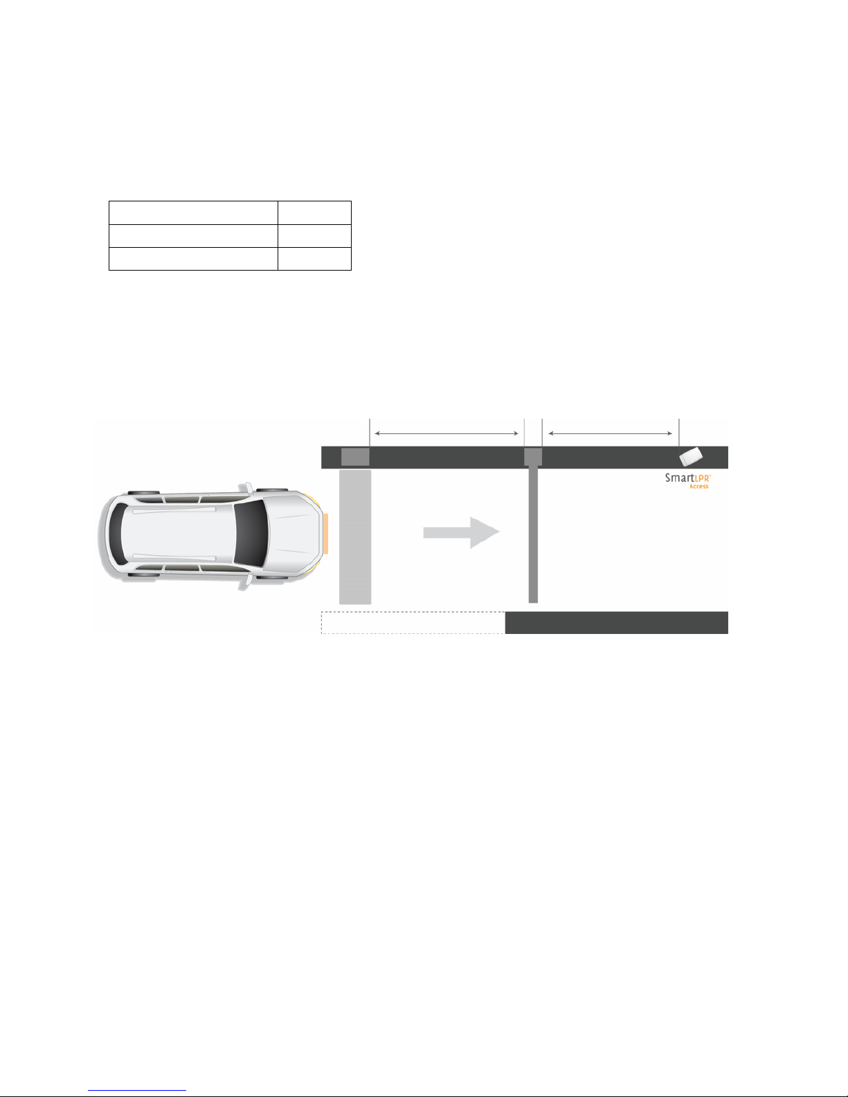
2.1. Front plate capture
2.1.1. Front plate capture
Recommended
2,5 – 3 m
Minimum distance
1,5 m
Maximum distance
5 m
The unit must always be installed at 2,5-3m from the barrier. In this type of installation, the
LPR unit captures the license plate when the vehicle arms the presence loop installed in line with
the ticket dispenser, as shown in the drawing below.
Warning:
The table above shows the recommended, minimum and maximum distance where you should
install the unit taking the barrier as reference.
3m
Barrier
Presence detection sensor
2,5m
Page 17

SmartLPR® Access User Manual Installation
Quercus Technologies 18
2.1.2. Queue management in installations for front plate capture
Queues are usually formed in barrier-controlled accesses, thus you have to make sure that the
license plate of the arriving vehicle will be fully seen. To this end, we recommend the use of two
metal loops: the second one should be placed under the barrier so that when the vehicle is no
longer on it, it won't appear in the image. This way, the vehicle does not appear in the images
of the vehicle that enters after it (the sequence of image capture starts when the first loop
reports presence and the second one doesn't report it any more).
Incorrect
Vehicle detection sensor pressed
Correct
Queue detection sensor free
Page 18

SmartLPR® Access User Manual Installation
Quercus Technologies 19
2.2. Rear plate capture
2.2.1. Rear plate capture
In installations for rear plate capture, we recommend installing a presence detector before the
one installed in line with the ticket dispenser. In this way you make sure that the camera captures
the license plate when the vehicle releases the first sensor (called “LPR sensor” in the drawing).
The recommended distance between the camera and the LPR sensor is 2,5m.
2.2.2. Queue management in installations for rear plate capture
In installations for rear plate capture, the best way to manage situations when queues are
formed is by installing a speed bump in line with the camera and before the LPR sensor that
triggers the capture. This way, a vehicle that enters after the first one must slow down and it
won't interfere in the capture taken of the first vehicle.
2,5m
6m
3m
Barrier
LPR sensor
Presence detection sensor
2,5m
6m
3m
Barrier
Presence detection sensor
LPRSensor
Speed bump
Page 19

SmartLPR® Access User Manual Installation
Quercus Technologies 20
2.3. Ceiling installation
In case the unit must be installed on the ceiling, the minimum horizontal distance from the unit
to the license plate must be of 5 m and the angle between the unit and the floor must not exceed
30º.
The maximum height where the unit could be installed (h), can be calculated as
follows:
h=L·tanβ
where for a minimum horizontal distance of 5 m, we get h= 2.9 m.
2.4. Electrical installation and cables needed
Each SmartLPR® Access recognition unit must have the following cables:
● Power cable: 3x1.5mm2 or 3x2.5mm2 section cable (alternating current) or 2x1.5mm2
(direct current).
● Shielded Network cable: UTP cable, category 5 (ethernet networking).
● Signal cable: 7-pin shielded cable (if the 2 inputs, one output and Wiegand
communication are required) with a 0.5mm
2
cross-section.
For more information about the power consumption of each unit, please refer to the “Technical Data
Sheets” downloaded at http://downloads.quercus.biz/.
Distance (L≥5m)
Height (h)
Camera angle (β≤30º)
Page 20

SmartLPR® Access User Manual Installation
Quercus Technologies 21
3. Supplied material
3.1. List of materials for cabinet models
1. Recognition unit
2. Quick start guide
3. Sun shield (optional)
4. Base fixing screws
5. 3 connectors (power, signals, network)
1 2 3 4 5
Page 21

SmartLPR® Access User Manual Installation
Quercus Technologies 22
Page 22

SmartLPR® Access User Manual Installation
Quercus Technologies 23
3.2. List of materials for camera housing models
1. Recognition unit
2. 3 external connectors (power, signals, network)
3. Quick start guide
3.3. Optional parts for camera housing models
1. Wall support
2. Floor / ceiling kit (floor/ceiling bracket + iron sheet + spacer)
3. Pole kit (wall bracket + tube adapter)
1 2 3 1 2
3
Page 23

SmartLPR® Access User Manual Installation
Quercus Technologies 24
4.1. Unit installation
4.1.1. Cabinet housing unit installation
Open the unit. Use a standard triangular 8mm wrench / 8mm
triangular spanner.
Pass the cables inside the cabinet.
Connect the cables to their pin. (check 4.2. Wiring and pinouts).
Place the unit so that the glass should point approximately to the
center of the lane.
Page 24

SmartLPR® Access User Manual Installation
Quercus Technologies 25
Fix the unit to the floor. Let the screws untighten as you'll have
to rotate the cabinet to correctly adjust the image. (see section
4.3. Focus).
Place the sun shield.
To know how to make these cables, go to 4.2. Wiring and pinouts.
4.1.2. Camera housing unit installation
Camera housing units are designed to be installed, with the corresponding optional components,
in the following configurations:
● Wall. Using wall bracket.
● Ceiling. Using floor/ceiling kit.
● Floor. Using floor/ceiling kit.
● Vertical Cylindrical Mast. Using vertical pole kit.
All types of installation are described next.
Keep the screws of the swivel head loose to be able to follow the installation steps described.
Page 25

SmartLPR® Access User Manual Installation
Quercus Technologies 26
4.1.2.1 Wall installation
Place the unit on the bracket.
Place the bracket on the wall.
4.1.2.2. Ceiling installation
Remove the iron plate of the swivel head and
keep the screws for the final step.
Place the swivel head on the vertical bracket.
Page 26

SmartLPR® Access User Manual Installation
Quercus Technologies 27
Fix the iron sheet on the unit using the spacer
provided.
Place the unit on the bracket, keeping the
longer side of the bracket in the front.
Install the bracket on the ceiling.
4.1.2.3. Floor installation
Remove the iron sheet from the swivel head
(you will not need it for this kind of
installation).
Place the swivel head on the vertical bracket.
Page 27

SmartLPR® Access User Manual Installation
Quercus Technologies 28
Place the unit on the bracket keeping the
longer side of the bracket in the front.
Fix the unit to the floor.
4.1.2.4. Vertical pole installation
Place the unit on the wall bracket.
Fix the wall bracket to the pole bracket.
Page 28

SmartLPR® Access User Manual Installation
Quercus Technologies 29
Place the assembly obtained on the vertical
pole.
4.1.2. Common procedures
This section describes all the procedures common to all the installation methods of the camera
housing models (ceiling, wall, mast, floor, etc.).
1. Connect the network cable.
2. Connect the power supply cable.
3. Connect the input/outputs cable (if needed).
4.2. Wiring and pinouts
This section describes all the steps you need to follow in order to make the cables (power, digital
I/O-if necessary-, and the network cable) used in both cabinet and camera housing installation.
4.2.1 Making the cables
Steps for assembling the DC power cable:
Remove the cable gland from the main body of the
connector
Page 29

SmartLPR® Access User Manual Installation
Quercus Technologies 30
Unscrew the main body of the connector.
Pass the cables through the cable glands and through the
main body of the connector.
5
Tighten the main body of the connector.
Tighten the cable glands at the bottom of the connector.
Steps for assembling the AC power cable:
Remove the cable gland from the main body of the
connector.
Unscrew the main body of the connector.
Pin
Meaning
1
+12V
2
GND
Page 30

SmartLPR® Access User Manual Installation
Quercus Technologies 31
Pass the cables through the cable glands and through the
main body of the connector.
5
Tighten the main body of the connector.
Tighten the cable glands at the bottom of the connector.
To assemble the network cable, follow these steps:
Unscrew the back side of the cable boot.
Pin
Meaning
1
Neutral
2
Line
3
N/C
E
Protective Earth
Page 31

SmartLPR® Access User Manual Installation
Quercus Technologies 32
Pass the cables through the cable glands
and through the boot.
Crimp the RJ-45 connector.
Place the RJ-45 connector inside the boot
and close it.
Please note: the boot is essential
in order to assure the leak
tightness of the unit.
Steps for assembling the I/O cables (if needed):
Remove the cable gland from the main body of the
connector.
Unscrew the main body of the connector.
Pass the cables through the cable glands and through the
main body of the connector.
diameter (rear view)
Page 32

SmartLPR® Access User Manual Installation
Quercus Technologies 33
5
Tighten the main body of the connector.
Tighten the cable glands at the bottom of the connector.
Once you have all the cables made, connect them to the unit and tighten firmly.
For the camera housing models, seal the connectors you did not use with the sealing cap supplied.
4.2.2. Input/Output system characteristics
The inputs have two possible states: in open circuit they indicate “0” the and in ground short
circuit they indicate “1”.
The output provides an open circuit or a ground short-circuit and leads a current of up to 200mA.
Example of an output layout with relay:
Pin
Meaning
1
IN1
2
IN2
3
OUT1
4
+ 12V
5
GND
6
Wiegand D0
7
Wiegand D1
Page 33

SmartLPR® Access User Manual Installation
Quercus Technologies 34
4.3. Focus
To adjust the camera follow the next steps:
1. Connect the unit to power.
2. Connect the crossover cable to the unit and the laptop.
3. Switch on the laptop and go to the web browser.
4. Go to http://<IP address of the unit> (see it on the label).
5. Type the password, "quercus 2" to enter setup.
6. Select the unit you want to adjust.
7. Place a license plate or a car centered on the lane at the beginning of the presence loop
(usually in front of the ticket dispenser) and make sure the license appears in the center of the
image. Follow the next steps:
Cabinet models:
● Rotate the cabinet until the license plate you see in the image is slightly oriented to the
opposite side of the camera. For instance, if you have installed the camera on the right (taking
as reference the way vehicles enter) side of the lane, the license has to be slightly on the left of
the image. On the contrary, if the camera is installed on the left side of the lane, the license in
the picture has to be on the right.
● Tighten the screws and firmly fix the cabinet on the floor.
Camera housing models:
● Loosen the screws of the swivel head.
● Rotate the unit until the license plate you see in the image is slightly oriented to the
opposite side of the camera. For instance, if you have installed the camera on the right (taking
as reference the way vehicles enter) side of the lane, the license has to be slightly on the left of
the image. On the contrary, if the camera is installed on the left side of the lane, the license in
the picture has to be on the right.
● Tighten the screws again.
8. From the "Camera" tab of the selected unit, use the +/- controls to set the focus and the
Page 34

SmartLPR® Access User Manual Installation
Quercus Technologies 35
zoom (the license plate must be in the center and the image sharp). Check section 5.2. Lens
adjustment to know how to correctly use these adjustment options. Adjust the zoom and the
focus until you get a license plate at a ¼ scale to the whole image. (The size of the license plate
you see on the image should have approximately 140-150 pixels from first to last character.)
(for normal resolution model)
9. Make sure that the adjustment covers all the positions in which a license plate can appear.
Click on "Recognize" to read the license plate and check if the recognition system is working in
any lane position.
4.4. Closing the unit
Once the installation is done, follow these steps:
1. Remove the network crossover cable from the laptop.
2. Connect the network cable.
3. For the cabinet models, put the lid of the unit back in place.
Page 35

SmartLPR® Access User Manual Configuration
Quercus Technologies 36
Configuration
Page 36

SmartLPR® Access User Manual Configuration
Quercus Technologies 37
4. Configuration system
Each SmartLPR® Access unit has an embedded configuration web from where you can configure
all the units in an installation at the same time.
To configure the units in an installation you must follow the next steps:
5.1. Login
Go to http://<IP address of the unit> (check the label of the unit), select “Normal” option and
type the password (by default "quercus2").
5.2. Lens adjustment
Once you are logged in, "Camera" window will appear. Here you can set the focus and the
zoom of the lens.
To make it easier to set the focus, adjust the brightness of the image by using the +/- controls
in "Brightness" tab.
You can adjust the lens by using the +/- zoom and focus controls.
To make sure you've properly adjusted the lens, click "Recognition" to request the license plate
recognition in the image.
LOGIN
MULTI-UNIT CONFIGURATION
CONFIGURE UNITS
APPLY CHANGES
LENS ADJUST
Page 37

SmartLPR® Access User Manual Configuration
Quercus Technologies 38
5.3. “Multi-unit configuration”
Press on “Multi-unit configuration” menu to see all the units found in the system. Click on the
icon that represents a camera to adjust the focus/zoom of each unit; once you have adjusted all
the units, go back to “Multi-unit configuration” tab. We will see a list with all the units found in
the system each of them with its IP address, description and firmware version.
Click on “Refresh” to refresh this list and “Save changes” to save the changes made in this
section.
Page 38

SmartLPR® Access User Manual Configuration
Quercus Technologies 39
5.4. Configure the units
To configure each unit go to the button menu at the top left corner of the screen. Click on
"Configuration" . There are various submenus with different configuration variables. It is very
important to click "Save changes" to save the changes made in each submenu.
● COMMUNICATIONS:
● Gateway: gateway to Internet access. Used when the central system is out of the
local network of the unit, otherwise it can be left pointing to “127.0.0.1”.
● NetMask: network mask of the unit.
● Central System Host 1: IP address of the central system.
● Central System Host 2: (optional) IP address of the second central system.
Page 39

SmartLPR® Access User Manual Configuration
Quercus Technologies 40
● RECOGNITION: configuration of the recognition engine of the unit.
● WorkingMode: the operation mode of the unit. Possible values:
● Software: it is the central system that determines when the plate recognition
should take place.
● Hardware: the unit detects vehicle movements and determines when the
recognition should take place (every time a new vehicle arrives).
● Pre-trigger: the unit is continually recognizing license plates as vehicles are
approaching and internally stores the best recognition. When the client
application request the license plate, the unit immediately sends it.
● Pre-arming loop: the unit directly receives from a loop installed at the
beginning of the lane a signal indicating the recognition must start. When the
client application sends a recognition request, SmartLPR® Access sends the best
recognition result.
● Regions: the available regions are on the left and the ones you have selected on the
right. Too add or remove regions, use the arrows. Also use the arrows to define the
priority order in the "Current" column.
● Advanced settings: variables for the advanced configuration, only available to
expert users.
Page 40

SmartLPR® Access User Manual Configuration
Quercus Technologies 41
● OSD:
● Main options: Parameters that configure the information to be overprinted as text
straight on the image.
● Active: sets the OSD system active or not.
● Position: image position where the text should be displayed.
● Labels: information on each OSD line. By default, the date and license plate of the
image recognized appear. To change or add more information, check 6.3. OSD
section.
● DATE & TIME SETTINGS:
● Configure date and time: configures the automatic synchronization of the hour with
an external server.
● Time protocol: protocol used in date and time synchronization. Its possible
values are “TIME” and “NTP”. If set to “TIME”, the protocol used will be the one
specified in “ARPA Internet RFC 868” document; if set to “NTP”, the protocol used
will be Network Time Protocol.
● Time server: date and time server that will synchronize the unit once a day.
● TimeZone: time zone of the computer. Useful to make sure that the date and
time synchronization takes into account time zone differences. The possible values
are the ones in zoneinfo data base (http://www.iana.org/time-zones).
Page 41

SmartLPR® Access User Manual Configuration
Quercus Technologies 42
5.5. Apply changes
To apply the configuration press "Apply" in the "Apply changes" menu.
You can select the units you want to apply the changes to and also the changes you want to
apply.
The units need to restart to make the new settings operational and this can take up to 1 minute.
Page 42

SmartLPR® Access User Manual Advanced Concepts
Quercus Technologies 43
Advanced concepts
Page 43

SmartLPR® Access User Manual Advanced Concepts
Quercus Technologies 44
6.1. Firmware update
To update the firmware means to incorporate in the unit newer versions of SmartLPR system in
order either to fix some errors or to include new functionalities.
6.1.1. Steps required before updating
Before installing an update, you first have to make it available on the unit. Follow these steps:
Remarks
1
Warning: NEVER try to install an update that
does not come directly from the
Quercus Technologies support department, as you
could permanently damage the unit firmware. If
fraudulent manipulation of the firmware
installed is detected, the product warranty will
be canceled immediately.
2
Open an FTP connection to the unit
(address ftp://<unit_IP>).
The identification and password are the same as
those used to enter configuration (default user
“admin”, password “quercus2”). If you access it
from Microsoft Internet Explorer, use
ftp://admin@<unit_IP> as address and enter the
password when asked.
3
Upload the update file to the FTP server.
4
Close the FTP connection.
Please note that the data uploaded in the FTP server will not be permanently stored (it is lost
every time the unit restarts) so upload the file only when you actually plan for the update to
take place.
6.1.2. Update
When the file has been uploaded to the FTP server you can update the system. To do that, select
“Update Firmware” option from the menu.
If there are update files available in the server, the system will ask you which file you wish to
use, select the right file (normally there will only be one available). The window that appears
describes the series of actions that will take place. If you agree, click “Update”.
Page 44

SmartLPR® Access User Manual Advanced Concepts
Quercus Technologies 45
Once the update is finished, a window with the result of the update will appear, and the unit will
restart, now operating with the new firmware.
Updating the unit firmware is a delicate operation. If you still have doubts about the process,
contact Quercus Technologies support department who will guide you through so that you can
carry out the update safely. Moreover, take into account the following:
1.The firmware update does not modify the current setup of the unit. However, the
new firmware might require the configuration of additional parameters (initially found
at their default value). See the documentation attached with the update to understand
what you have to do when the update is finished.
2. Do not update the system if there is a high probability of temporary power cuts.
3. The SmartLPR® unit will not be functional while the update takes place. Do not do this at times
when you need the unit to remain operational.
4. Make sure the update has been carried out successfully. To do this, check the version
returned by the unit before and after the process, for example using the "System Information"
function from the main menu.
6.2. The behavior of the control led
The control Led has 4 possible status: off, blue, red and green. The combinations and their
meaning are described next:
● blue: the system is initializing.
● flashing blue light: can mean two things:
a) data disk is being checked (during initializing).
b) data disk is being formatted (at user's command).
● red: there has been an error and the unit is no longer functioning correctly. Check the
log file (on the configuration web) to find out more about the error.
● green: the system functions correctly.
● red / blue (flashing): can have two meanings and in both cases the user MUST NOT
SHUT DOWN the unit while the lights are flashing as it can cause irreversible damages:
a) system is updating (at user's command).
b) system is restoring to the original version (also at user's command).
● red (flashing): some critical errors affected the system and they cannot be solved
automatically. Go to the configuration web by writing the original IP address of the unit
and follow the steps here to correct the errors manually.
Page 45

SmartLPR® Access User Manual Advanced Concepts
Quercus Technologies 46
6.3. OSD
Every OSD line has both text and variables which will be replaced by a specific value in each
recognition; a line can have up to 63 characters. You will find a description of the available
variables at the last page of the present paper.
In order to define a variable, mark it with a "$", followed by the identifier and two brackets where
the configuration will be written.
$name_of_the_variable(configuration_of_the_variable)
Depending on the variable format the configuration mode changes. The present formats are:
● Text: does not allow configuration. Example: identifier of the unit.
Example 1: identifier of the unit.
$carId()
● Time: its value expresses a date, with microsecond accuracy. Example: moment when
the incident occurred.
You must indicate the date format in the configuration paragraph, using at least one of the
following sequences. You can place text strings to make it more comprehensible.
○ %u: relative microseconds.
○ %m: relative milliseconds.
○ %c: relative centiseconds.
○ %d: deciseconds.
○ %S: second.
○ %M: minute.
○ %H: hour.
○ %D: day.
○ %T: month.
○ %Y: year.
○ %I: date and hour in ISO 8601 format.
In all these sequences, except for the one in ISO 8601 format, it is possible to indicate the
minimum number length by adding the following values between the "%" and the sequence
identifier:
● "X" where X is the minimum length of the number, right-justified and without spaces.
● "0X" where X is the minimum length of the number, right-justified and filled with zeros.
Example 1: hour with microsecond accuracy.
$timestamp(hours %H, minutes %M, seconds %S, milliseconds %m,
Page 46

SmartLPR® Access User Manual Advanced Concepts
Quercus Technologies 47
microseconds %u)
Example 2: hour with millisecond accuracy.
$timestamp( %Y/%02T/%02D %02H:%02M:%02S.%03m)
Examples
Configuration 1: Moment: $timestamp( %Y/%02T/%02D %02H:%02M:%02S.%03m).”
Possible result 1: Moment: 2014/05/18 13:01:20.711.”
Configuration 2: “Unit $unitId(), Vehicle $carId() - $license().”
Possible result 2: “Unit 35, Vehicle 27 – 1111 AAA.”
Page 47

SmartLPR® Access User Manual Advanced Concepts
Quercus Technologies 48
Variables available in OSD
Description
Identifier of the variable
Format
Vehicle identifier.
carId
Text
Identifier of the trigger that led to the recognition.
TriggerId
Text
Shows if the license matches any known grammar.
grammarOk
Text
Character or Characters identifying the country of the
recognized license.
country
Text
Recognized license without blanks, hyphens or any
additional decoration.
chars
Text
Number of unknown chars (displayed as question
marks in the license).
numberOfUnknownChars
Text
Average quality of the recognized license plate (from
0 to 1).
avgQuality
Text
Identifier of the unit.
unitId
Text
Recognized license with the corresponding additional
decoration (blanks, hyphens, etc.). If the license
doesn't match with any known grammar, this field will
not contain any decoration.
License
Text
Quality of the recognized character (from 0 to 1).
minQuality
Text
Rectangle inside the image where the license was
found, in “(<left>,<up>)-(<right>,<down>)” format.
If the license doesn't match with any grammar, or it is
empty, the value of this field will be the image
dimensions.
roi
Text
Date and time of the recognition.
timestamp
Date
Unit description
description
Text
Page 48

SmartLPR® Access User Manual Annexes
Quercus Technologies 49
Annexes
Page 49

SmartLPR® Access User Manual Annexes
Quercus Technologies 50
1. 7. Annex A: Table of product references and technical specifications
Format
Power
Extra
Resolution
Color image
Temperature
control
North-America
version
Name
Reference
Cabinet
Painted
Stainless
steel
cabinet
Camera
Housing
AC
DC
●
●
SmartLPR Access A AC
07000400 ●
●
●
SmartLPR Access NA A AC
07000410
●
●
●
SmartLPR Access A AC CT
07000402
● ● ● ●
SmartLPR Access NA A AC CT
07000411
● ● ●
SmartLPR Access A WL AC
07000404
● ● ● ●
SmartLPR Access NA A WL AC
07000412
● ● ● ●
SmartLPR Access A WL AC CT
07000406
● ● ● ● ●
SmartLPR Access NA A WL AC CT
07000413
● ● ● ●
SmartLPR Access A CL WL AC
07000414
● ● ● ● ●
SmartLPR Access NA A CL WL AC
07000415
● ● ● ● ●
SmartLPR Access A CL WL AC CT
07000416
● ● ● ● ● ●
SmartLPR Access NA A CL WL AC CT
07000417
● ●
SmartLPR Access A DC
07000401
● ● ●
SmartLPR Access NA A DC
07000418
● ● ●
SmartLPR Access A DC CT
07000403
● ● ● ●
SmartLPR Access NA A DC CT
07000419
● ● ●
SmartLPR Access A WL DC
07000405
● ● ● ●
SmartLPR Access NA A WL DC
07000420
● ● ● ●
SmartLPR Access A WL DC CT
07000407
● ● ● ● ●
SmartLPR Access NA A WL DC CT
07000421
● ● ● ●
SmartLPR Access A CL WL DC
07000408
● ● ● ● ● ●
SmartLPR Access NA A CL WL DC
07000422
● ● ● ● ●
SmartLPR Access A CL WL DC CT
07000409
● ● ● ● ● ● ●
SmartLPR Access NA A CL WL DC CT
07000423
● ●
SmartLPR Access I AC
07000424
● ● ●
SmartLPR Access NA I AC
07000425
Page 50

SmartLPR® Access User Manual Annexes
Quercus Technologies 51
Format
Power
Extra
Resolution
Color image
Temperature
control
North-America
version
Name
Reference
Cabinet
Painted
Stainless
steel
cabinet
Camera
Housing
AC
DC
● ● ●
SmartLPR Access I AC CT
07000426
● ● ● ●
SmartLPR Access NA I AC CT
07000427
● ● ●
SmartLPR Access I WL AC
07000428
● ● ● ●
SmartLPR Access NA I WL AC
07000429
● ● ● ●
SmartLPR Access I WL AC CT
07000430
● ● ● ● ●
SmartLPR Access NA I WL AC CT
07000431
● ● ● ●
SmartLPR Access I CL WL AC
07000432
● ● ● ● ●
SmartLPR Access NA I CL WL AC
07000433
● ● ● ● ●
SmartLPR Access I CL WL AC CT
07000434
● ● ● ● ● ●
SmartLPR Access NA I CL WL AC CT
07000435
● ●
SmartLPR Access I DC
07000436
● ● ●
SmartLPR Access NA I DC
07000437
● ● ●
SmartLPR Access I DC CT
07000438
● ● ● ●
SmartLPR Access NA I DC CT
07000439
● ● ●
SmartLPR Access I WL DC
07000440
● ● ● ●
SmartLPR Access NA I WL DC
07000441
● ● ● ●
SmartLPR Access I WL DC CT
07000442
● ● ● ● ●
SmartLPR Access NA I WL DC CT
07000443
● ● ● ●
SmartLPR Access I CL WL DC
07000444
● ● ● ● ●
SmartLPR Access NA I CL WL DC
07000445
● ● ● ● ●
SmartLPR Access I CL WL DC CT
07000446
● ● ● ● ● ●
SmartLPR Access NA I CL WL DC CT
07000447
● ●
SmartLPR Access C AC
07000450
● ● ●
SmartLPR Access NA C AC
07000460
● ● ●
SmartLPR Access C AC CT
07000452
● ● ● ●
SmartLPR Access NA C AC CT
07000461
● ● ●
SmartLPR Access C WL AC
07000454
● ● ● ●
SmartLPR Access NA C WL AC
07000462
Page 51

SmartLPR® Access User Manual Annexes
Quercus Technologies 52
Format
Power
Extra
Resolution
Color image
Temperature
control
North-America
version
Name
Reference
Cabinet
Painted
Stainless
steel
cabinet
Camera
Housing
AC
DC
● ● ● ●
SmartLPR Access C WL AC CT
07000456
● ● ● ● ●
SmartLPR Access NA C WL AC CT
07000463
● ● ● ●
SmartLPR Access C CL WL AC
07000464
● ● ● ● ●
SmartLPR Access NA C CL WL AC
07000465
● ● ● ● ●
SmartLPR Access C CL WL AC CT
07000466
● ● ● ● ● ●
SmartLPR Access NA C CL WL AC CT
07000467
● ●
SmartLPR Access C DC
07000451
● ● ●
SmartLPR Access NA C DC
07000468
● ● ●
SmartLPR Access C DC CT
07000453
● ● ● ●
SmartLPR Access NA C DC CT
07000469
● ● ●
SmartLPR Access C WL DC
07000455
● ● ● ●
SmartLPR Access NA C WL DC
07000470
● ● ● ●
SmartLPR Access C WL DC CT
07000457
● ● ● ● ●
SmartLPR Access NA C WL DC CT
07000471
● ● ● ●
SmartLPR Access C CL WL DC
07000458
● ● ● ● ●
SmartLPR Access NA C CL WL DC
07000472
● ● ● ● ●
SmartLPR Access C CL WL DC CT
07000459
● ● ● ● ● ●
SmartLPR Access NA C CL WL DC CT
07000473
The data sheets with the corresponding technical specifications for each model can be downloaded at
http://downloads.quercus.biz/, “Technical Data Sheets”.
Page 52

8. Annex B: CE Certificates
Products with CE Certificate (see the Technical Specifications Datasheets at
www.downoloads.quercus.biz) have Class A category. In a domestic environment this product
may cause radio interference, in which case the user has to take adequate actions.
Warning
This is a class A product. In a domestic environment this product may cause radio interference
in which case the user may be required to take adequate measures.
Page 53

SmartLPR® Access User Manual Annexes
Quercus Technologies 54
DECLARATION OF CONFORMITY
Manufacturer’s Name: Quercus Technologies, SL
Manufacturer’s Address: Av. Onze de Setembre 19, 43203 (Reus), Spain
Telephone: +34 977 300 377
Declare under our sole responsibility that the following equipment:
Type of equipment: License plate recognition system
Brand name: QUERCUS
Models:
SmartLPR Access C AC
SmartLPR Access C AC CT
SmartLPR Access C WL AC
SmartLPR Access C WL AC CT
SmartLPR Access C CL WL AC
SmartLPR Access C CL WL AC CT
SmartLPR Access NA C WL AC
SmartLPR Access NA C WL AC CT
SmartLPR Access NA C CL WL AC
SmartLPR Access NA C CL WL AC CT
Conforms to the following Product Specifications and Regulations:
Directive: Electromagnetic Compatibility Directive (EMC) 2004/108/EC Applicable standards:
• EN 55024:2010 “Information technology equipment. Immunity characteristics. Limits and methods
of measurement.
• EN 55022:2006 “Information technology equipment. Radio disturbance characteristics. Limits and
methods of measurement.”
Directive: Low Voltage 2006/95/CE. Applicable standards:
• EN 60950-1:2006 “Information technology equipment - Safety -- Part 1: General requirements”
Place and date: Reus, 13th of May of 2015 Signed by: Albert Mateu López
R&D Director
Page 54

SmartLPR® Access User Manual Annexes
Quercus Technologies 55
DECLARATION OF CONFORMITY
Manufacturer’s Name: Quercus Technologies, SL
Manufacturer’s Address: Av. Onze de Setembre 19, 43203 (Reus), Spain
Telephone: +34 977 300 377
Declare under our sole responsibility that the following equipment:
Type of equipment: License plate recognition system
Brand name: QUERCUS
Models:
SmartLPR Access C DC
SmartLPR Access A DC CT
SmartLPR Access C WL DC
SmartLPR Access A WL DC CT
SmartLPR Access C CL WL DC
SmartLPR Access C CL WL DC CT
SmartLPR Access NA C WL DC
SmartLPR Access NA C WL DC CT
SmartLPR Access NA C CL WL DC
SmartLPR Access NA C CL WL DC CT
Conforms to the following Product Specifications and Regulations:
Directive: Electromagnetic Compatibility Directive (EMC) 2004/108/EC Applicable standards:
• EN 55024:2010 “Information technology equipment. Immunity characteristics. Limits and methods
of measurement.
• EN 55022:2006 “Information technology equipment. Radio disturbance characteristics. Limits and
methods of measurement.”
Place and date: Reus, 13th of May of 2015 Signed by: Albert Mateu López
R&D Director
Page 55

SmartLPR® Access User Manual Annexes
Quercus Technologies 56
DECLARATION OF CONFORMITY
Manufacturer’s Name: Quercus Technologies, SL
Manufacturer’s Address: Av. Onze de Setembre 19, 43203 (Reus), Spain
Telephone: +34 977 300 377
Declare under our sole responsibility that the following equipment:
Type of equipment: License plate recognition system
Brand name: QUERCUS
Models:
SmartLPR Access A AC
SmartLPR Access A AC CT
SmartLPR Access A WL AC
SmartLPR Access A WL AC CT
SmartLPR Access I AC
SmartLPR Access I AC CT
SmartLPR Access I WL AC
SmartLPR Access I WL AC CT
SmartLPR Access A CL WL AC
SmartLPR Access A CL WL AC CT
SmartLPR Access I CL WL AC
SmartLPR Access I CL WL AC CT
SmartLPR Access NA A WL AC
SmartLPR Access NA A WL AC CT
SmartLPR Access NA A CL WL AC
SmartLPR Access NA A CL WL AC CT
SmartLPR Access NA I WL AC
SmartLPR Access NA I WL AC CT
SmartLPR Access NA I CL WL AC
SmartLPR Access NA I CL WL AC CT
Conforms to the following Product Specifications and Regulations:
Directive: Electromagnetic Compatibility Directive (EMC) 2004/108/EC. Applicable standards:
• EN 55024:2010 “Information technology equipment. Immunity characteristics. Limits and methods
of measurement.
• EN 55022:2006 “Information technology equipment. Radio disturbance characteristics. Limits and
methods of measurement.”
Directive: Low Voltage 2006/95/CE. Applicable standards:
• EN 60950-1:2006 “Information technology equipment - Safety -- Part 1: General requirements”
Place and date: Reus, 13th of May of 2015 Signed by: Albert Mateu López
R&D Director
Page 56

SmartLPR® Access User Manual Annexes
Quercus Technologies 57
DECLARATION OF CONFORMITY
Manufacturer’s Name: Quercus Technologies, SL
Manufacturer’s Address: Av. Onze de Setembre 19, 43203 (Reus), Spain
Telephone: +34 977 300 377
Declare under our sole responsibility that the following equipment:
Type of equipment: License plate recognition system
Brand name: QUERCUS
Models:
SmartLPR Access A DC
SmartLPR Access A DC CT
SmartLPR Access A WL DC
SmartLPR Access A WL DC CT
SmartLPR Access I DC
SmartLPR Access I DC CT
SmartLPR Access I WL DC
SmartLPR Access I WL DC CT
SmartLPR Access A CL WL DC
SmartLPR Access A CL WL DC CT
SmartLPR Access I CL WL DC
SmartLPR Access I CL WL DC CT
SmartLPR Access NA A WL DC
SmartLPR Access NA A WL DC CT
SmartLPR Access NA A CL WL DC
SmartLPR Access NA A CL WL DC CT
SmartLPR Access NA I WL DC
SmartLPR Access NA I WL DC CT
SmartLPR Access NA I CL WL DC
SmartLPR Access NA I CL WL DC CT
Conforms to the following Product Specifications and Regulations:
Directive: Electromagnetic Compatibility Directive (EMC) 2004/108/EC. Applicable standards:
• EN 55024:2010 “Information technology equipment. Immunity characteristics. Limits and methods
of measurement.
• EN 55022:2006 “Information technology equipment. Radio disturbance characteristics. Limits and
methods of measurement.”
Page 57

SmartLPR® Access User Manual Annexes
Quercus Technologies 58
Place and date: Reus, 13th of May of 2015 Signed by: Albert Mateu López
R&D Director
Page 58

SmartLPR® Access User Manual Annexes
Quercus Technologies 59
9. Annex C: FCC Certificate
Warning
This equipment (see Technical Specifications Datasheets at www.downoloads.quercus.biz) has
been tested and found to comply with the limits for a Class A digital device, pursuant to part
15 of the FCC Rules. These limits are designed to provide reasonable protection against harmful
interference when the equipment is operated in a commercial environment.
This equipment generates, uses, and can radiate radio frequency energy and, if not installed
and used in accordance with the instruction manual, may cause harmful interference to radio
communications. Operation of this equipment in a residential area is likely to cause harmful
interference in which case the user will be required to correct the interference at his own
expense.
Page 59

SmartLPR® Access User Manual Annexes
Quercus Technologies 60
DECLARATION OF CONFORMITY
Manufacturer’s Name: Quercus Technologies, SL
Manufacturer’s Address: Av. Onze de Setembre 43203 (Reus), Spain
Telephone: +34 977 300 377
Declare under our sole responsibility that the following equipment:
Type of equipment: License plate recognition system
Brand name: QUERCUS
Models:
SmartLPR Access A AC
SmartLPR Access A AC CT
SmartLPR Access A WL AC
SmartLPR Access A WL AC CT
SmartLPR Access I AC
SmartLPR Access I AC CT
SmartLPR Access I WL AC
SmartLPR Access I WL AC CT
SmartLPR Access A CL WL AC
SmartLPR Access A CL WL AC CT
SmartLPR Access I CL WL AC
SmartLPR Access I CL WL AC CT
SmartLPR Access NA A WL AC
SmartLPR Access NA A WL AC CT
SmartLPR Access NA A CL WL AC
SmartLPR Access NA A CL WL AC CT
SmartLPR Access NA I WL AC
SmartLPR Access NA I WL AC CT
SmartLPR Access NA I CL WL AC
SmartLPR Access NA I CL WL AC CT
To which this declaration relates is in conformity with the following specifications:
• FCC CFR47 Part 15, subpart B, Class A Digital Device.
This device complies with Part 15 of the FCC Rules. Operation is subject to the following two conditions:
(1) this device may not cause harmful interference, and (2) this device must accept any interference
received, including interference that may cause undesired operation.
Place and date: Reus, 13th of May of 2015 Signed by: Albert Mateu López
Page 60

SmartLPR® Access User Manual Annexes
Quercus Technologies 61
R&D Director
Page 61

SmartLPR® Access User Manual Annexes
Quercus Technologies 62
DECLARATION OF CONFORMITY
Manufacturer’s Name: Quercus Technologies, SL
Manufacturer’s Address: Av. Onze de Setembre 19, 43203 (Reus), Spain
Telephone: +34 977 300 377
Declare under our sole responsibility that the following equipment:
Type of equipment: License plate recognition system
Brand name: QUERCUS
Models:
SmartLPR Access A DC
SmartLPR Access A DC CT
SmartLPR Access A WL DC
SmartLPR Access A WL DC CT
SmartLPR Access I DC
SmartLPR Access I DC CT
SmartLPR Access I WL DC
SmartLPR Access I WL DC CT
SmartLPR Access A CL WL DC
SmartLPR Access A CL WL DC CT
SmartLPR Access I CL WL DC
SmartLPR Access I CL WL DC CT
SmartLPR Access NA A WL DC
SmartLPR Access NA A WL DC CT
SmartLPR Access NA A CL WL DC
SmartLPR Access NA A CL WL DC CT
SmartLPR Access NA I WL DC
SmartLPR Access NA I WL DC CT
SmartLPR Access NA I CL WL DC
SmartLPR Access NA I CL WL DC CT
To which this declaration relates is in conformity with the following specifications:
• FCC CFR47 Part 15, subpart B, Class A Digital Device.
This device complies with Part 15 of the FCC Rules. Operation is subject to the following two conditions:
(1) this device may not cause harmful interference, and (2) this device must accept any interference
received, including interference that may cause undesired operation.
Place and date: Reus, 13th of May of 2015 Signed by: Albert Mateu López
R&D Director
Page 62

SmartLPR® Access User Manual Annexes
Quercus Technologies 63
Page 63

SmartLPR® Access User Manual Annexes
Quercus Technologies 64
DECLARATION OF CONFORMITY
Manufacturer’s Name: Quercus Technologies, SL
Manufacturer’s Address: Av. Onze de Setembre 19, 43203 (Reus), Spain
Telephone: +34 977 300 377
Declare under our sole responsibility that the following equipment:
Type of equipment: License plate recognition system
Brand name: QUERCUS
Models:
SmartLPR Access C AC
SmartLPR Access C AC CT
SmartLPR Access C WL AC
SmartLPR Access C WL AC CT
SmartLPR Access C CL WL AC
SmartLPR Access C CL WL AC CT
SmartLPR Access NA C WL AC
SmartLPR Access NA C WL AC CT
SmartLPR Access NA C CL WL AC
SmartLPR Access NA C CL WL AC CT
To which this declaration relates is in conformity with the following specifications:
• FCC CFR47 Part 15, subpart B, Class A Digital Device.
This device complies with Part 15 of the FCC Rules. Operation is subject to the following two conditions:
(1) this device may not cause harmful interference, and (2) this device must accept any interference
received, including interference that may cause undesired operation.
Place and date: Reus, 13th of May of 2015 Signed by: Albert Mateu López
R&D Director
Page 64

SmartLPR® Access User Manual Annexes
Quercus Technologies 65
DECLARATION OF CONFORMITY
Manufacturer’s Name: Quercus Technologies, SL
Manufacturer’s Address: Av. Onze de Setembre 19, 43203 (Reus), Spain
Telephone: +34 977 300 377
Declare under our sole responsibility that the following equipment:
Type of equipment: License plate recognition system
Brand name: QUERCUS
Models:
SmartLPR Access C DC
SmartLPR Access A DC CT
SmartLPR Access C WL DC
SmartLPR Access A WL DC CT
SmartLPR Access C CL WL DC
SmartLPR Access C CL WL DC CT
SmartLPR Access NA C WL DC
SmartLPR Access NA C WL DC CT
SmartLPR Access NA C CL WL DC
SmartLPR Access NA C CL WL DC CT
To which this declaration relates is in conformity with the following specifications:
• FCC CFR47 Part 15, subpart B, Class A Digital Device.
This device complies with Part 15 of the FCC Rules. Operation is subject to the following two conditions:
(1) this device may not cause harmful interference, and (2) this device must accept any interference
received, including interference that may cause undesired operation.
Place and date: Reus, 13th of May of 2015 Signed by: Albert Mateu López
R&D Director
Page 65

6 Kingsbridge Road, Unit 8, Faireld, NJ 07004
Phone: (862) 505-2101
Fax: (862) 204-5906
www.zkaccess.com
© Copyright 2014. ZKTeco Inc. ZKTeco Logo and ZKAccess Logo are registered trademarks of ZKTeco or a
related company. All other product and company names mentioned are used for identification purposes
only and may be the trademarks of their respective owners. All specifications are subject to change without
notice. All rights reserved.
ZKAccess - a division of ZKTeco
 Loading...