

Page 1

3 inches Facial & Fingerprint Recognition
Series Product User Manual
Version: 3.3
Date: May. 2012
About This Manual
This document introduces the user interface and menu operations
of 3 inches Facial & Fingerprint Recognition Series product. For
installation, please refer to the
Guide.
Installation Guide or Quick
Page 2

Page 3

Important Claim
Firstly thank you for purchasing this facial and fingerprint hybrid
terminal, before use, please read this manual carefully to avoid
the unnecessary damage! The company reminds you that the
proper user will improve the use affect and authentication speed.
No written consent by our company, any unit or individual isn’t
allowed to excerpt, copy the content of this manual in part or in full,
also spread in any form.
The product described in the manual maybe includes the software
which copyrights are shared by the licensors including our
company, Except for the permission of the relevant holder, any
person can’t copy, distribute, revise, modify, extract, decompile,
disassemble, decrypt, reverse engineering, leasing, transfer,
sub-license the software, other acts of copyright infringement, but
the limitations applied to the law is excluded.
Due to the constant renewal of products, the company can not
undertake the actual product in consistence with the information
in the document, also any dispute caused by the difference
between the actual technical parameters and the information in
this document. Please forgive any change without notice.
Page 4

About this manual
Not all the devices have the function with. The real product prevails.
The photograph in this manual may be different from that of the real
product. The real product prevails.
Page 5

Contents
Table of Contents
1. Instructions for Use................................................................ 1
1.1 Standing Position, Posture and Face Expressions ............. 1
1.2 Enrollment Face Expressions ............................................. 2
1.3 Finger Placement ............................................................. 3
1.4 Use of the Touch Screen .................................................... 4
1.5 Touch Operations ............................................................... 5
1.6 Appearance of Device ......................................................... 7
1.7 Main Interface ................................................................... 10
1.8 Verification Modes ............................................................ 12
1.8.1 Fingerprint Verification
1.8.2 Face Verification ......................................................... 14
1.8.3 Password Verification ................................................. 16
1.8.4 ID Card Verification
1.8.5 Combination Verification
............................................. 12
.................................................. 17
.......................................... 18
2. Main Menu ............................................................................. 21
3. Add User................................................................................ 24
3.1 Entering a User ID ............................................................ 25
3.2 Entering a Name ............................................................... 26
3.3 Enrolling a Fingerprint .................................................... 27
3.4 Enrolling a Password ........................................................ 29
3.5 Enrolling an ID card ....................................................... 30
3.6 Enrolling a Face ................................................................ 31
3.7 Entering a Group No. ..................................................... 32
3.8 Modifying User Rights ....................................................... 33
3.9 Enroll Photo ................................................................... 34
I
Page 6

Contents
3.10 User Access Settings ................................................... 35
4. User Management ................................................................ 38
4.1 Edit a User ........................................................................ 39
4.2 Delete a User .................................................................... 40
4.3 Query a User .................................................................... 41
5. Communication Settings ..................................................... 42
5.1 Communication Settings ................................................... 43
5.2 WIFI Configuration ......................................................... 45
5.3 Wiegand Output ............................................................. 49
5.3.1 Wiegand 26-bits Output Description ........................... 49
5.3.2 Wiegand 34-bits Output Description ........................... 51
5.3.3 Customized Format .................................................... 52
5.4 Wiegand Input ............................................................... 57
6. System Settings ................................................................... 58
6.1 General Parameters .......................................................... 59
6.2 Interface Parameters ........................................................ 60
6.3 Fingerprint Parameters .................................................. 61
6.4 Face Parameters .............................................................. 63
6.5 Log Settings ...................................................................... 65
6.6 Shortcut Definitions ........................................................... 66
6.7 Access Settings ............................................................. 69
6.7.1 Time zone setting ....................................................... 69
6.7.2 Holiday setting ............................................................ 70
6.7.3 Group time zone setting ............................................. 72
6.7.4 Unlock Combination Setting ....................................... 74
6.7.5 Access control parameter ........................................... 76
II
Page 7

Contents
6.7.6 Duress Alarm Parameters .......................................... 77
6.7.7 Anti-Pass back setting ................................................ 78
6.8 Update .............................................................................. 79
7. Data Management ................................................................. 80
7.1 Query Record ................................................................... 82
7.2 SMS ............................................................................... 84
7.2.1 Set a Short Message .................................................. 84
7.2.2 View a Short Message ............................................... 88
7.3 Work Code ........................................................................ 90
7.3.1 Add a work code ......................................................... 90
7.3.2 Edit and delete a work code ....................................... 91
7.3.3. Edit and delete a work code ...................................... 91
8. Date/Time Setting ................................................................. 92
8.1 Set Date/Time ................................................................... 92
8.2 Bell Setting .................................................................... 93
8.3 Daylight Saving Time (DLST) ........................................ 95
9. Auto Test ............................................................................... 97
10. USB Disk Management ...................................................... 99
11. System Information .......................................................... 100
12. Appendix ........................................................................... 101
12.1 T9 Input Instructions ..................................................... 101
12.2 USB .............................................................................. 103
12.3 Introduction of Wiegand ............................................. 104
12.4 Photo ID Function ...................................................... 106
12.5 Work Code ................................................................. 107
III
Page 8

Contents
12.6 Print function .............................................................. 108
12.7 Multi-combination Authentication Mode ..................... 113
12.8 Anti-Pass Back .......................................................... 117
12.9 Statement on Human Rights and Privacy ..................... 120
12.10 Environment-Friendly Use Description ........................ 122
IV
Page 9

Error! Use the Home tab to apply 标题 1 to the text that you want to appear
here.
1. Instructions for Use
1.1 Standing Position, Posture and Face
Expressions
1. Recommended standing-distance from
device:
For users 5-6 feet tall (1.55m-1.85m) we
recommend users stand about 2 feet (0.5m) from the
wall.
When viewing your image on the device display window, step away if your
image appears too bright. Step closer if your image appears too dark.
2. Recommended face Expressions vs. poor Expressions:
3. Recommended Posture (pose) vs. poor Posture (pose):
Note: During enrollment and verification, try to have a relaxed
unstrained face expression and stand upright.
1
Page 10

3 inches Facial & Fingerprint Recognition Series Product User Manual
1.2 Enrollment Face Expressions
During the enrollment, position your head such way that your face appears in
the center of the device display window, and follow the voice prompts "Focus
eyes inside the green box". The user needs to move forward and backward to
adjust the eyes position during the face registration. The enrollment face
expressions as follows:
2
Page 11

Error! Use the Home tab to apply 标题 1 to the text that you want to appear
sensor
here.
1.3 Finger Placement
Recommended fingers: The index finger, middle finger or the ring finger is
recommended; the thumb and little finger are not recommended (because
they are usually clumsy when pressing on the fingerprint collection screen).
1. Proper finger placement
2. Improper finger placement
The finger must be flat to the surface
and centered on the fingerprint
.
Not flat to the surface
Slanting
Please enroll and verify your fingerprint by using the proper finger placement
mode. We shall not be held accountable for any consequences arising out of the
degradation in verification performance due to improper user operations. We shall
reserve the right of final interpretation and revision of this document.
3
Off-center
Off-center
Page 12

3 inches Facial & Fingerprint Recognition Series Product User Manual
1.4 Use of the Touch Screen
Touch the screen with one of your fingertips or the edge of a fingernail, as
shown in the following figure. A broad point of contact may lead to inaccurate
pointing.
When the touch screen is less sensitive to the touch, you can perform a
screen calibration through the following menu operations. Press [Menu] ->
[Auto Test] -> [Calibration] on the screen and a cross icon will be displayed.
After you touch the center of the cross at five locations on the screen correctly,
the system will automatically returns to the Auto Test menu. Press [Exit] to
return to the Menu interface. For details, see the description in 9. Auto Test.
Smear or dust on the touch screen may affect the performance of the touch
screen. Therefore, try to keep the screen clean and dust-free.
4
Page 13

Error! Use the Home tab to apply 标题 1 to the text that you want to appear
here.
1.5 Touch Operations
1. Enter numbers: Press the [User ID] key. The system will automatically
display the number input interface. After entering the user ID, press [OK] to
save or press [X] to cancel and return to the previous interface.
2. Enter Text: Press the [Name] key. The system will automatically display
the text input interface. After entering the user name, press [X] to save and
return to the previous interface.
5
Page 14

3 inches Facial & Fingerprint Recognition Series Product User Manual
3. Modify parameters: Press the default value of a parameter and the
system will automatically switch to another value of this parameter.
Note: The Enroll Fingerprint, User Access and 1: G is optional function,
only some machines have.
6
Page 15

Error! Use the Home tab to apply 标题 1 to the text that you want to appear
here.
1.6 Appearance of Device
1. Type 1
(1) Front View
LED Indicator
Touch Screen
Touch keys
Camera
Push Buttons
Fingerprint Sensor
(2) Side View
ID Card Swipe Area
Reset Button
USB Port
7
Page 16

3 inches Facial & Fingerprint Recognition Series Product User Manual
2. Type 2
(1) Front View
LED Indicator
Touch Screen
Touch keys
Camera
ID Card Swipe Area
(2) Side View
USB Port
8
Page 17

Error! Use the Home tab to apply 标题 1 to the text that you want to appear
here.
3. Type 3
(1) Front View
LED Indicator
Touch Screen
Touch Keys
Camera
Push Buttons
ID Card Swipe Area
(2) Side View
Reset Button
USB Port
9
Page 18

3 inches Facial & Fingerprint Recognition Series Product User Manual
1.7 Main Interface
Date
Time
Attendance Status
Date: The current date is displayed.
Screen Shortcut Keys: Press these shortcut keys to display the
attendance status. Users can customize the function of each shortcut key.
For details, see 6.6 Shortcut Definitions.
Time: The current time is displayed. Both 12-hour and 24-hour time
systems are supported.
Attendance Status: The current attendance status is displayed.
1:1Switch Key: By pressing this key, you can switch to the 1:1verification
modes, and enter the digital input interface.
1:1 Switch Key
Menu
10
Page 19

Error! Use the Home tab to apply 标题 1 to the text that you want to appear
here.
Menu: You can enter the main menu by pressing this key.
Note: 1. The Enroll Fingerprint, User Access, Door Bell Button and 1:1
Switch Button is an optional function, some machines have
these function.
2. The 1: G is an optional function. If you need this function,
please consult our commercial representatives or fore-sale
technical support personal.
11
Page 20

3 inches Facial & Fingerprint Recognition Series Product User Manual
1.8 Verification Modes
1.8.1 Fingerprint Verification
1. 1: N fingerprint verification
The terminal compares current fingerprint collected by the fingerprint
collector with all fingerprint data on the terminal.
(1) To enter the fingerprint verification mode. The device automatically
distinguishes face and fingerprint verification, just pressing finger on the
collector. Shall be fingerprint authentication mode.
(2) Press your finger on the fingerprint sensor by adopting the proper finger
placement. For details, see 1.3 Finger Placement.
(3) If the verification is successful, the device will prompt “Verified”.
(4) If the verification is not successful, the device will prompt “Please try again”.
2. 1:1 fingerprint verification
In the 1:1 fingerprint verification mode, the device compares current
fingerprint collected through the fingerprint sensor with that in relation to the
user ID entered through the keyboard. Adopt this mode only when it is difficult
to recognize the fingerprint.
12
Page 21

Error! Use the Home tab to apply 标题 1 to the text that you want to appear
here.
(1) Press [1:1] on the screen or [1:1] button to enter the 1:1 fingerprint
recognition mode.
(2) Enter User ID or Group No., then press the "Fingerprint” icon to enter the
1:1 fingerprint recognition mode. If the prompt “Unregistered user!” is
displayed, the user ID does not exist.
(3) Press your finger on the fingerprint sensor by adopting the proper finger
placement. For details, see 1.3 Finger Placement.
(4) If the verification is successful, the device will prompt “Verified”, otherwise
the device will prompt “Please try again”.
13
Page 22

3 inches Facial & Fingerprint Recognition Series Product User Manual
1.8.2 Face Verification
1. 1: N Face Verification
The terminal compares current face image collected
by the camera with all face data on the terminal.
(1) The device automatically distinguishes face and
fingerprint verification.
(2) Compare the facial in a proper way. For details, see
1.1 Standing Position, Posture and Face Expressions.
Comparison of interface display the current image
collected by the camera, an interface as shown in
Figure 1 on the right will be displayed.
(3) If the verification is successful, an interface as
shown in Figure 2 on the right will be displayed.
2. 1:1 face verification
In the 1:1 face verification mode, the device compares
current face collected through the camera with that in
relation to the user ID entered through the keyboard.
Adopt this mode only when it is difficult to recognize
the face.
(1) Press [1:1] on the screen button to enter the 1:1
recognition mode.
(2) Enter User ID, then press the "1:1 Face" icon to enter
1:1 face recognition mode. If the prompt "Unregistered
user!" is displayed, the user ID does not exist.
(3) Compare the face in a proper way. For details, see
14
Page 23

Error! Use the Home tab to apply 标题 1 to the text that you want to appear
here.
1.1 Standing Position, Posture and Face Expressions.
(4) If the verification is successful, the device will prompt "Verified". The system
will return to the main interface if the verification is not passed within 20 seconds.
3. 1: G Face Verification
When you open the 1: G Verify function, then you can make 1: G facial
verification. For detail please see 6.5 Log Settings.
Current group No. (Valid group number is 1-5) is
displayed on the facial recognition interface. Users in
current group can perform facial comparison directly.
Users of another group can perform facial comparison
only after entering the group No. or selecting it using
the shortcut key. And the system will set the group
entered or selected by users to be the current group
instantly.
(1) Press [1:1/1: G] on the screen to enter the 1: G
recognition mode.
(2) Enter user Group No. and then press the "1: G” icon (shown as following
15
Page 24

3 inches Facial & Fingerprint Recognition Series Product User Manual
figure 1) to enter 1: G facial recognition mode.
(3) Compare the facial in a proper way. For details, see 1.1 Standing Position,
Posture and Face Expressions. Current Group No. is displayed on the
comparison interface, shown as following figure 2.
Note: Check whether you are in current group; if not, return to Step 1.
(4) If the verification is successful, shown as following figure 3.
Note: The 1: G Face group is an optional function. Some machines
have this function. But some have not. Face group function is untapped by
Factory default, users can set in System--Log
Settings--1: G Verify to open this function.
1.8.3 Password Verification
In the password verification mode, the device
compares the password entered with that in relation to
the user ID.
1. Press [1:1] on the screen or [1:1] button to enter the
password verification mode.
16
Page 25

Error! Use the Home tab to apply 标题 1 to the text that you want to appear
here.
2. Enter the user ID and then press the "Key” icon to enter the password
verification mode. If the prompt “Unregistered user!” is displayed, the user ID
does not exist.
3. Enter the password and press the “OK” icon to start the password
comparison.
4. If the verification is successful, the device will prompt “Verified”, otherwise
the device will prompt “Verify fail” and return to password input interface.
1.8.4 ID Card Verification
Only the products with a built-in ID card module support the ID card
verification. The products with a built-in ID card module support the following
two verification modes:
ID Card Only: Users only need to swipe their ID cards for verification.
ID + Facial Verification: After passing the ID card verification, you also need
to perform facial verification.
1. ID Card Only
1) Swipe your ID card on the card swipe area by adopting the proper way.
For the card swipe area, see 1.6 Appearance of Device.
2) If the verification is successful, the device will prompt “Verified”.
17
Page 26

3 inches Facial & Fingerprint Recognition Series Product User Manual
3) If the verification is not successful, the device will prompt “Not Enrolled”.
Note:
(1) The machines that have Photo ID function’s successful verification
interface is shown as figure 1 above;
(2) The machines that don’t have Photo ID function’s successful verification
interface is shown as figure 2 above.
2. ID + Facial Verification
(1) Swipe your ID card properly at the swiping area to
enter the 1:1 facial verification mode.
(2) Compare the facial in a proper way. For details, see
1.1 Standing Position, Posture and Face Expressions.
(3) If the verification is successful, an interface as
shown in Figure 3 on the right will be displayed. The
system will return to the main interface if the verification
is not passed within 20 seconds.
1.8.5 Combination Verification
The device supports up to 20 verification modes, including
18
Page 27

Error! Use the Home tab to apply 标题 1 to the text that you want to appear
here.
FACE&PIN/FP/RF/PW、FP&PW、FP&RF、FACE&FP、FACE&PW、FACE&RF、
FP、PW、RF、FACE&PIN、FP/RF、PW/RF、FP/PW、PW&RF、PIN&FP、
FP&PW&RF、PIN&FP&PW、FP&RF/PIN、FACE&FP&RF、FACE&FP&PW
etc. For the detail, please refer to 12.7 Multi-combination Authentication
Mode.
Note: RF means ID card verification. Only the products with the built-in
ID card module support the ID card verification.
Here is the combination verification operation; we will use the FACE&FP
verification for an example.
If you verify the fingerprint first and then the face, the operations are as
follows.
1. The default main interface is the fingerprint verification mode, see the
figure below.
2. Press your finger on the fingerprint sensor by adopting the proper finger
placement. For details, see 1.3 Finger Placement.
3. If the verification is successful, the device will enter the 1:1 face recognition
mode. Compare the face in a proper way. For details, see 1.1 Standing Position,
Posture and Face Expressions.
19
Page 28

3 inches Facial & Fingerprint Recognition Series Product User Manual
4. If the verification is successful, the device will prompt “Verified”. The
system will return to the main interface if the verification is not passed within
20 seconds.
Otherwise, the FACE&FP combination verification can perform such as FACE
(1: N) + FP, PIN + FACE (1:1) + FP, PIN + FP (1:1) + FACE etc. The operation
is similar to the procedure introduced before.
20
Page 29

2. Main Menu
2. Main Menu
There are two types of rights respectively granted to two types of users: the
Ordinary users and administrators. Ordinary users are only granted the
rights of face, fingerprint, password or card verification, while administrators
are granted access to the main menu for various operations apart from
having all the privileges granted to ordinary users.
Press [Menu] on the initial interface to access the main menu, as shown in
the following figure:
The main menu includes nine sub menus:
Add User: Through this submenu, you can add a new user and input the
information on the device, including the user ID, name, fingerprint, face,
card, password, rights, group No. and user access.
User Mgt.: Through this submenu, you can browse the user information
stored on the device, including the user ID, name, fingerprint, face, card,
password, rights, group No. and user access. Here you can also add,
21
Page 30

3 inches Facial & Fingerprint Recognition Series Product User Manual
modify or delete a user’s information.
Comm.: Through this submenu, you can set related parameters for
communication between the device and PC, including the IP address,
gateway, subnet mask, baud rate, device No. and communication
password.
System: Through this submenu, you can set system-related parameters,
including the basic parameters, interface parameters, fingerprint, face and
attendance parameters, Keyboard definitions, Access settings, firmware
update etc. to enable the device to meet the user’s requirements to the
greatest extent in terms of functionality and display.
Data Mgt.: Through this submenu, you can perform management of data
stored on the device, for example, deleting the attendance records, all data,
clear administrator, restore to factory settings and query records.
Date/Time: Through this submenu, you can set the alarm time and duration,
or set the Bell.
Auto Test: This submenu enables the system to automatically test whether
functions of various modules are normal, including the screen, sensor, voice,
face, keyboard, clock tests and screen calibration.
Dn/Upload: Through this submenu, you can download user information and
attendance data stored in the device through a USB disk to related software
or other fingerprint recognition equipment.
Sys Info.: Through this submenu, you can browse the records and device
22
Page 31

2. Main Menu
information.
Any user can access the main menu by pressing the [Menu] key if
the system does not have an administrator. After administrators are
configured on the device, the device needs to verify the administrators’
identity before granting them access to the main menu. To ensure device
security, it is recommended to set an administrator when using the
terminal initially. For detailed operations, see 3.8 Modifying User Right.
23
Page 32

3 inches Facial & Fingerprint Recognition Series Product User Manual
3. Add User
Press [Add] on the [User Mgt.] interface to display the
[Add User] interface as shown below.
User ID: Enter a user ID. 1 to 9 digits user IDs are
supported by default.
Name: Enter a user name. 12 characters user names
are supported by default.
Fingerprint: Enroll a user’s fingerprint and the device
displays the number of enrolled fingerprints. A user can
enroll 10 fingerprints at maximum.
Password: Enroll a user’s password. The device supports
1-8 digit passwords by default.
Face: Enroll a user’s face.
Group No.: Setting in the group of user.
Role: Set the rights of a user. A user is set to ordinary
user by default and can also be set to administrator.
Ordinary users are only granted the rights of face,
fingerprint or password verification, while administrators
are granted access to the main menu for various
operations apart from having all the privileges granted to
ordinary users.
Photo: Enroll a user’s photo. During user verification is success; the user’s
photo is displayed on screen.
User Access: Set the lock control and access control parameters.
24
Page 33

Error! Use the Home tab to apply 标题 1 to the text that you want to appear
here.
3.1 Entering a User ID
The device automatically allocates an ID starting from
1 for every user in sequence. If you use the ID
allocated by the device, you may skip this section.
1. Press [User ID] on the [Add User] interface to
display the user ID management interface.
Tip: The user ID can be modified during initial
enrollment, but once enrolled, it cannot be
modified.
2. On the displayed keyboard interface, enter a user ID
and press [OK]. If the message “The user ID already
exists!” is displayed, enter another ID.
Tip: The device supports 1 to 9 digits user IDs
by default. If you need to extend the length of
current user ID numbers, please consult our
commercial representatives or technical pre-sales.
3. After the user ID is entered, press [Save] to save the
current information and return to the previous interface.
Press [Exit] to return to the previous interface without
saving the current information.
25
Page 34

3 inches Facial & Fingerprint Recognition Series Product User Manual
3.2 Entering a Name
Use T9 input method to enter the user name through
the keyboard.
1. Press [Name] on the [Add User] interface to
display the name input interface.
2. On the displayed keyboard interface, enter a user
name and press [X].
For details of operations on the keyboard interface,
see 12.1 T9 Input Instructions.
3. After the user name is entered, press [Save] to
save the current information and return to the
previous interface. Press [Exit] to return to the previous interface without
saving the current information.
Tip: The device supports the 1 to 12 characters names by default.
26
Page 35

Error! Use the Home tab to apply 标题 1 to the text that you want to appear
here.
3.3 Enrolling a Fingerprint
1. Press [Fingerprint] on the [Add User] interface to
display the [Enroll Fingerprint] interface.
2. On the displayed [Enroll Fingerprint] interface,
place your finger on the fingerprint sensor properly
according to the system prompt. For details, see 1.3
Finger Placement.
3. Place the same finger on the fingerprint sensor for
three consecutive times correctly. If the enrollment
succeeds, the system will display a prompt message
and automatically return to the [Add User] interface. If
the enrollment fails, the system will display a prompt message and return to
the [Enroll Fingerprint] interface. In this case, you need to repeat the
operations of step 2.
4. You can enroll the backup fingerprint by pressing [Fingerprint] again. A
user can enroll 10 fingerprints at maximum.
5. Press [Save] to save the current information and return to the previous
interface. Press [Exit] to return to the previous interface without saving the
current information.
27
Page 36

3 inches Facial & Fingerprint Recognition Series Product User Manual
28
Page 37

Error! Use the Home tab to apply 标题 1 to the text that you want to appear
here.
3.4 Enrolling a Password
1. Press [Password] on the [Add User] interface to
display the password management interface.
2. On the displayed keyboard interface, enter a
password and press [OK]. Re-enter the password
according to the system prompt and then press [OK].
Tip: The device supports 1-8 digit passwords
by default.
3. After the password is entered, an interface is
displayed as shown below. Press [Save] to save the
current information and return to the previous interface. Press [Exit] to return
to the previous interface without saving the current information.
29
Page 38

3 inches Facial & Fingerprint Recognition Series Product User Manual
3.5 Enrolling an ID card
1. Press [Card] on the [Add User] interface to display
the [Enroll Card] interface.
2. The [Punch Card!] interface pops up as shown below.
Swipe your ID card properly in the swiping area. For
details, see 1.6 Appearance of Device.
3. If the card passes the verification, the device will
display a prompt message “Read Successfully! Card No.:
**********”, and returns to the [Add User] interface.
4. Press [Save] to save the current information and
return to the previous interface. Press [Exit] to return
to the previous interface without saving the current information.
Note: 3 inches Facial & Fingerprint Recognition support Mifare card
function. It is an option function, if you want to customize the Mifare card
function, please consult our commercial representatives or pre-sales
technical support engineers.
30
Page 39

Error! Use the Home tab to apply 标题 1 to the text that you want to appear
here.
3.6 Enrolling a Face
1. Press [Face] on the [Add User] interface to display
the face enrollment interface.
2. On the displayed face enrollment interface, turn
your head to the left and right slightly, raise and lower
your head according to the voice prompts, so as to
enroll different parts of your face into the system to
assure the accurate verification. See 1.2 Enrollment
Face Expressions.
3. If your face image is enrolled successfully, the
system will display a prompt message and
automatically return to the [Add User] interface.
4. Press [Save] to save the current information and return to the previous
interface. Press [Exit] to return to the previous interface without saving the
current information.
31
Page 40

3 inches Facial & Fingerprint Recognition Series Product User Manual
3.7 Entering a Group No.
1. Press [Group No.] on the [Add User] interface to display the group No.
management interface.
2. On the displayed keyboard interface, enter your group No. and press [OK].
3. After the group No. is entered, an interface is displayed as shown below.
Press [Save] to save the current information and return to the previous
interface. Press [Exit] to return to the previous interface without saving the
current information.
32
Page 41

Error! Use the Home tab to apply 标题 1 to the text that you want to appear
here.
3.8 Modifying User Rights
Note: There are two types of rights respectively granted to two types of
users: the ordinary users and administrators. Ordinary users are only
granted the rights of face, fingerprint, or password verification, while
administrators are granted the access to the main menu for various
operations apart from having all the privileges granted to ordinary users.
1. On the [Add User] interface, press [Role: User] to change the user to an
administrator.
2. After the modification is done, the interface is as shown below. Press
[Save] to save the current information and return to the previous interface;
press [Exit] to return to the previous interface without saving the current
information.
33
Page 42

3 inches Facial & Fingerprint Recognition Series Product User Manual
3.9 Enroll Photo
If you had enrolled your photo in the system, the
system will display your enrolled photo in addition to
your ID and name after you pass the verification.
1. Press [Photo] on the [Add User] interface to display
the photo enrollment interface.
2. On the photo enrollment interface, stand naturally
in front of the screen. For details, see 1.1 Standing
Position, Posture and Face Expressions. Press
[Capture] to capture the photo.
3. After taking the photo, press [Exit] to return to the
previous interface.
4. After the photo is taken, press [Save] to save the current information and
return to the previous interface; press [Exit] to return to the previous interface
without saving the current information.
34
Page 43

Error! Use the Home tab to apply 标题 1 to the text that you want to appear
here.
3.10 User Access Settings
Press [User Access] on the
[Add User] interface to display
the user access settings
interface.
User Access settings are to
set the user’s rights to verify
and open the door, such as the
Verify Type, Time Zone and
Duress FP management.
1. Verify Type
(1) Group Verify Mode: If the
user uses the group verify mode
that he belong to.
(2) Individual verify mode:
Select the verification mode
for this user instead of the
group verify mode. That will
not affect other users in this
group.
Note:
(1) Only the products with the built-in ID card module support the ID card
verification.
(2) For the verify type, please refer to12.7 Multi-combination Authentication
Mode.Only some types of devices support Multi-combination authentication
35
Page 44

3 inches Facial & Fingerprint Recognition Series Product User Manual
mode.
2. Time Zone
(1) Group Time Zone: If the user uses the group time zone that he belong to.
(2) Individual time zone: Select the time zone of this user instead of the
group time zone. That will not affect other users in the group.
3. Duress FP
User can register a new duress fingerprint or cancel
registered duress fingerprints. If a finger is registered
duress fingerprints. When compare it, will trigger the
duress alarm signal.
If cancel the duress fingerprints, does not delete the
fingerprints data, still can use the fingerprints process
normal comparison.
Duress FP management:
(1) Register Duress FP
Press [Reg. Duress FP] on the [User Access] interface
to display the [Enroll Fingerprint] interface. On the displayed [Enroll
Fingerprint] interface, place your finger on the fingerprint sensor properly
according to the system prompt. For details, see 1.3 Finger Placement.
36
Page 45

Error! Use the Home tab to apply 标题 1 to the text that you want to appear
here.
(2) Cancel duress FP
Press [Can. Duress FP] on the [User Access] interface to pop-pup the
confirm message. Select [YES] to delete the enrolled duress FP, otherwise
select [NO] to cancel the operation.
37
Page 46

3 inches Facial & Fingerprint Recognition Series Product User Manual
4. User Management
Browse the user information, including the user ID, name, fingerprint, face,
ID card, password, rights, group No. and user access settings through
this interface. To add, edit or delete the basic information of users.
Press [User Management] on the main menu interface to display the user
management interface.
This user is an administrator.
Note: The users are listed in alphabetical order by last name. If you
press a user name, you can access the editing interface of this user to edit or
delete the related user’s information.
38
Page 47

4. User Management
4.1 Edit a User
Press a user name from the list to enter the [User Info] interface.
The User ID cannot be modified, and the other operations are similar to those
performed in add a user. You can re-enroll your fingerprint and face,
change your password, modify the management rights and Group No.
For example: Change the user rights from Administrator to ordinary user. As
shown below.
39
Page 48

3 inches Facial & Fingerprint Recognition Series Product User Manual
4.2 Delete a User
On the [User Info] interface, you can delete all or partial user information.
1. Press [Delete] to delete a user.
2. On the displayed interface, click [YES] to delete the current user or [NO] to
return to the previous interface.
3. On the [User Info] interface, press [Name], [Fingerprint], [Face] or
[Password] to delete the related user information and to re-enroll the new
information follow the device prompt.
40
Page 49

4. User Management
4.3 Query a User
To facilitate administrators to locate a user quickly from a large number of
enrolled users, the device enables to query by “User ID”.
User ID Query:
1. Press [Query] on the [User Management] interface to display the User ID
query interface.
2. Enter the user ID on the displayed interface, and click [OK] to locate the
cursor on the desired user.
41
Page 50

3 inches Facial & Fingerprint Recognition Series Product User Manual
5. Communication Settings
You can set related parameters for the communication between the device
and PC, including the IP address, Gateway, Subnet Mask, Baud Rate,
Device ID, and Comm Key.
Note: The comm. (RS232/RS485), WIFI、Wiegand In and Wiegand Out
are optional function, only some machines have these functions.
42
Page 51

5. Communication Settings
5.1 Communication Settings
IP Address: The IP address is 192.168.1.201 by default and can be changed
as required.
Subnet Mask: The subnet mask is 255.255.255.0 by default and can be
changed as required.
Gateway: The gateway is 0.0.0.0 by default and can be changed as required.
(RS232/RS485), you need to check the following settings:
RS232: This parameter is used to enable or disable the RS232
communication. If the RS232 communication cables are used, set this
parameter to “ON”.
RS485: This parameter is used to enable or disable the RS485
communication. If the RS485 communication cables are used, set this
parameter to “ON”.
Baud Rate: This parameter is used to set the baud rate for the
communication between the device and the PC. It includes five options: 9600,
19200, 38400, 57600, and 115200. The higher baud rate is recommended for
the RS232 communication to achieve high speed communication, while the
lower baud rate is recommended for the RS485 communication to achieve
stable low-speed communication.
43
Page 52

3 inches Facial & Fingerprint Recognition Series Product User Manual
USB232: Decide whether use USB to communicate or not, that is to say if
you use the USB communication, and then selected the item as "Yes".
Otherwise as "No".
Device ID: This parameter is used to set the ID of device from 1 to 254. If the
RS232/RS485 communication is adopted, you need to enter the device ID on
the software communication interface.
Comm. Key: To enhance the security of attendance data, you can set a
password for the connection between the device and PC. Once the password
is set, you can connect the PC with the device to access the attendance data
only after entering the correct password. The default password is 0 (that is,
no password). Once a password is set, you need to enter this password
before connecting the PC software with the device; otherwise, the connection
is unsuccessful. 1 to 6 digits passwords are supported.
PrintMode:When user authentication is successful, you can choose
whether to print attendance information. Print mode can be set. In all, there
are 6 print modes available. See 12.7 Print function
Considering the massive data including the fingerprint and face templates
stored in the device, it is recommended to transfer the data between the device
and PC over network to enhance the transfer speed.
44
Page 53

5. Communication Settings
5.2 WIFI Configuration
1. Available WLANs
Available WLANs around a mobile phone can be searched. Select
Available WLAN to enter the Available WLAN interface and click
Refresh, then the available WLANs around the mobile phone are listed
on the interface, as well as their signal strengthen.
As shown in the third of the preceding figures, a user can search its
wireless route and set a password. For other settings, see the "WIFI
Configuration" in the following section. The password must be the same
as that of the wireless route so that the mobile phone can access to the
WLAN. Complete setting and click save button, the machine will
connect to the software automatically.The following figure shows the
initial interface when the mobile phone accesses to the WLAN:
45
Page 54

3 inches Facial & Fingerprint Recognition Series Product User Manual
2. WIFI Configuration
Before the mobile phone is accessed to the WLAN, other physical
components of the 802.11 network are required, including access points,
distribute systems, and wireless media. In addition, the service set
identifier (ESSID) must be available.
Network ID: specifies the network identification of the wireless network
to be accessed. (Letters are case-sensitive.)
Local IP address: If the 802.11 wireless network is not configured with
the function of dynamic host configuration protocol
(DHCP), enter the Manual IP Designation interface and
input an IP address, subnet mask, and gateway address.
Otherwise, dynamically designate an IP address.
Password: The password must be the same as that of the router so
that the mobile phone can access to the WIFI. (Only
support key1 in WEP model.)
IP address: When the setting of a local IP address is in manual mode,
designate and input a correct IP address, subnet mask,
and gateway address on the Manual IP Designation
46
Page 55

5. Communication Settings
interface. The designated IP address is the IP address of
a mobile phone in the wireless network, and does not
have any relationship with comm. WIFI IP can not share
the same network segment with the machine IP.
Subnet mask and gateway: The subnet mask and gateway address of
the designated IP address must be designated and input.
Operation Description
1) Set SSID
Select WIFI Configuration to enter the WIFI Configuration interface.
Click the inputting button of the Network ID and input the network ID
after starting the T9 inputting method editor (IME). The network ID
must be provided for identification.
2) Set a local IP address
Select a mode for designating a local IP address. The IP address is
designated in manual or DHCP mode.
3) Set a password
47
Page 56

3 inches Facial & Fingerprint Recognition Series Product User Manual
Click the inputting button of the password and input a password after
starting the T9 IME.
4) Designate an IP address
When the setting of local IP addresses is in manual mode, designate
and input a correct IP address, subnet mask, and gateway address on
the Manual IP designation interface. The designated IP address is the
IP address of a mobile phone in the wireless network, and does not
have any relationship with comm.
After an IP address is designated, click Save and return to the WIFI
Configuration interface.
After performing the preceding procedures, click Save and goes back to
the previous interface.
48
Page 57

5. Communication Settings
5.3 Wiegand Output
Wiegand Format: The system has two built-in formats Wiegand 26-bits and
Wiegand 34-bits, and also supports the format customization function to
meet individualized requirements.
Failed ID: Refers to the value output by the system
upon verification failure. The output format is subject
to the setting of “Wiegand Format”. The default
value scope of Failed ID is 0-65535.
Site Code: The site code is used for a customized
Wiegand format. The site code is similar to the device
ID, but the site code is customizable and can be
duplicated among different devices. The default value
scope of the Site Code is 0-255.
Pulse Width: Refers to the width of the Wiegand
pulse in microseconds. The default value scope of the pulse width is 1-1000.
Pulse Interval: Refers to the interval of the Wiegand pulse in microseconds.
The default value scope of the pulse width is 1-10000.
Output: Refers to the contents output upon successful verification. You can
select the “User ID” or “Card Number” as the output.
5.3.1 Wiegand 26-bits Output Description
The system has a built-in Wiegand 26-bits format. Press [Wiegand Format],
and select “Standard Wiegand 26-bits”.
The composition of the Wiegand 26-bits format contains 2 parity bits and 24
bits for output contents (“User ID” or “Card Number”). The binary code of
24-bits represent up to 16,777,216 (0–16,777,215) different values.
49
Page 58

3 inches Facial & Fingerprint Recognition Series Product User Manual
1 2 25 26
Even parity User ID/Card Number Odd parity bit
Definition of Fields:
Meaning
Field
Even parity bit
User ID/ Card
Number (bit 2-bit
25)
Odd parity bit
For example, for a user with the user ID of 12345, the enrolled card number
is 0013378512 and the failed ID is set to 1.
1. When the output is set to “User ID”, the Wiegand output is as follows upon
successful verification:
0 0 0 0 0 0 0 0 0 0 0 1 1 0 0 0 0 0 0 1 1 1 0 0 1 1
Even parity bit User ID = Binary code of 12345 Odd parity bit
2. When the output is set to “Card Number”, the Wiegand output is as follows
upon successful verification:
1 1 1 0 0 1 1 0 0 0 0 1 0 0 0 1 1 1 1 0 1 0 0 0 0 0
Even parity bit User ID = Binary code of 0013378512 Odd parity bit
3. The Wiegand output is as follows upon verification failure:
Judged from bit 2 to bit 13. The even parity bit is 1 if
the character has an even number of 1 bit; otherwise,
the even parity bit is 0.
User ID/Card Number (Card Code, 0–16777215)
Bit 2 is the Most Significant Bit (MSB).
Judged from bit 14 to bit 25. The odd parity bit is 1 if
the character has an even number of 1 bit; otherwise,
the odd parity bit is 0.
50
Page 59

5. Communication Settings
0 0 0 0 0 0 0 0 0 0 0 0 0 0 0 0 0 0 0 0 0 0 0 0 1 0
Even parity bit Failed ID = Binary code of 1 Odd parity bit
Note: If the output contents exceed the scope allowed for the Wiegand
format, the last several bits will be adopted and first several bits are
automatically discarded. For example, the user ID 888 888 888 is 110 100
111 110 110 101 111 000 111 000 in binary format. Wiegand26 only supports
24 bits, that is, it only outputs the last 24 bits, and first 6 bits “110 100” are
automatically discarded.
5.3.2 Wiegand 34-bits Output Description
The system has a built-in Wiegand 34-bits format. Press [Wiegand Format],
and select “Standard Wiegand 34-bits”.
The composition of the Wiegand 34-bits format contains 2 parity bits and 32
bits for output contents (“User ID” or “Card Number”). The binary code of
32-bits represent up to 4,294,967,296 (0–4,294,967,295) different values.
1 2 33 34
EvenParityBit User ID/Card Number Odd parity bit
Table 2 Definition of Fields
Field Meaning
Even parity bit
User ID/Card
Number (bit 2-bit
33)
Judged from bit 2 to bit 17. The even parity bit is 1 if
the character has an even number of 1 bit; otherwise,
the even parity bit is 0.
User ID/Card Number (Card Code, 0–4,294,967,295)
Bit 2 is the Most Significant Bit (MSB).
51
Page 60

3 inches Facial & Fingerprint Recognition Series Product User Manual
Odd parity bit
For example, for a user with the user ID of 123456789, the enrolled card
number is 0013378512 and the failed ID is set to 1.
1. When the output is set to “User ID”, the Wiegand output is as follows upon
successful verification:
0 0 0 0 0 0 1 1 1 0 1 0 1 1 0 1 1 1 1 0 0 1 1 0 1 0 0 0 1 0 1 0 1 1
Even parity bit User ID = Binary code of 123456789 Odd parity bit
2. When the output is set to “Card Number”, the Wiegand output is as follows
upon successful verification:
0 0 0 0 0 0 0 0 0 1 1 0 0 1 1 0 0 0 0 1 0 0 0 1 1 1 1 0 1 0 0 0 0 1
Even parity bit User ID = Binary code of 0013378512 Odd parity bit
3. The Wiegand output is as follows upon verification failure:
0 0 0 0 0 0 0 0 0 0 0 0 0 0 0 0 0 0 0 0 0 0 0 0 0 0 0 0 0 0 0 0 1 0
Even parity bit Failed ID = Binary code of 1 Odd parity bit
Judged from bit 18 to bit 33. The odd parity bit is 1 if
the character has an even number of 1 bit; otherwise,
the odd parity bit is 0.
5.3.3 Customized Format
Apart from the two built-in formats Wiegand 26-bits and Wiegand 34-bits,
the system also supports the format customization function to meet
individualized requirements.
The customized format consists of two character strings: the Card Format
bits and Parity Format bits. These two character strings need to be defined
separately.
Card Format bits define the number of binary bits output by Wiegand as well
52
Page 61

5. Communication Settings
as the meaning of each bit. The data bits output by Wiegand can be a card
number (C), site code (s), facility code (f), manufacturer code (m) and parity
bits (p).
Parity Format bits define the check mode of each bit in data bits and ensure
the correctness of data bits during transfer through the parity check. The
parity bits can be set to odd check (o), even check (e) and both odd check
and even check (b). There is a one-to-one correspondence relationship
between the data bits and parity bits.
For example, the Wiegand26 can be customized as follows:
Definition of Card Format bits: pssssssssccccccccccccccccp
Definition of Parity Format bits: eeeeeeeeeeeeeooooooooooooo
Note: Wiegand26 consists of 26 bits. The first bit is the even parity bit of
th
bits 2 to 13; the 26
ninth bits are the site code; the 10
For details about the Wiegand protocol, see 12.4 Introduction of Wiegand.
To customize Wiegand format, proceed as follows:
(1) Select [Define Format] and the [Set] key is then
enabled.
(2) Press [Set] to display the [User Define Format]
interface, as shown in the following figure:
(3) Click the entry box below “Card Format” to display the
following interface:
bit is the odd parity bit of bits 14 to 25; the second to the
th
to the 25th bits are the card number.
53
Page 62

3 inches Facial & Fingerprint Recognition Series Product User Manual
Display Input
Display the Numb
Cancel Input
Backspace
Confirm Input
Characters used to define Card Format bits and
their meanings:
c: Indicates the card number, that is, the output
contents, it can be set to User ID/Card Number
through menu operations.
f: Indicates the facility code which is 0 by default. It is
not configurable. To modify it, please contact the
equipment supplier.
m: Indicates the manufacturer code which is 0 by
default. It is not configurable. To modify it, please
contact the equipment supplier.
p: Indicates the parity position.
s: Indicates the site code which can be set from 0 to 255 by default.
(4) Click the entry box below “Parity Format” to display the following interface:
Characters used to define Parity Format bits and their meanings:
o: Indicates the odd check, that is, there is an odd number of 1’s in the bit
sequence (including one parity bit). For example, for 1000110(0), the parity
54
Clear Input
Page 63

5. Communication Settings
bit is 0 and there are already three 1’s. After 0 is suffixed to 1000110, there is
still an odd number of 1’s.
e: Indicates the even check, that is, there is an even number of 1’s in the bit
sequence (including one parity bit). For example, for 1000110(1), the parity
bit is 1 and there are already three 1’s. After 1 is suffixed to 1000110, there is
an even number of 1’s.
b: Indicates both odd check and even check.
For example, Definitions of several universal Wiegand formats.
Wiegand34
Card Format bits:
pccccccccccccccccccccccccccccccccp
Parity Format bits:
eeeeeeeeeeeeeeeeeooooooooooooooooo
Note: Wiegand34 consists of 34 bits. The first bit is the even parity bit of bits 2
to 17; the 34
bits are the site code; the 10
th
bit is the odd parity bit of bits 18 to 33; the second to the ninth
th
to the 25th bits are the card number.
Wiegand37a
Card Format bits: pmmmmsssssssssssscccccccccccccccccccp
Parity Format bits: oeobeobeobeobeobeobeobeobeobeobeobeoe
Note: Wiegand37a consists of 37 bits. The first bit is the odd parity bit of bits
3, 4, 6, 7, 9, 10, 12, 13, 15, 16, 18, 19, 21, 22, 24, 25, 27, 28, 30, 31, 33, 34
and 36; the 37
th
bit is the odd parity bit of bits 2, 4, 5, 7, 8, 10, 11, 13, 14, 16,
17, 19, 20, 22, 23, 25, 26, 28, 29, 31, 32, 34 and 35; bits 4, 7, 10, 13, 16, 19,
22, 25, 28, 31 and 34 participate in both odd and even parity check. Bits 2 to
5 are manufacturer code; bits 6 to 17 are the site code; bits 18 to 36 are the
card number.
55
Page 64

3 inches Facial & Fingerprint Recognition Series Product User Manual
Wiegand37
Card Format bits:
pmmmffffffffffssssssccccccccccccccccp
Parity Format bits:
eeeeeeeeeeeeeeeeeeooooooooooooooooooo
Note: Wiegand37 consists of 37 bits. The first bit is the even parity bit of bits 2
to 18; the 34
bits are the manufacturer code; the 5
th
15
to the 20th bits are the site code; the 21st to the 36th bits are the card
th
bit is the odd parity bit of bits 19 to 36; the second to the fourth
th
to the 14th bits are facilitate code; the
number.
Wiegand50
Card Format bits: pssssssssssssssssccccccccccccccccccccccccccccccccp
Parity Format bits:
eeeeeeeeeeeeeeeeeeeeeeeeeooooooooooooooooooooooooo
Note: Wiegand50 consists of 50 bits. The first bit is the even parity bit of bits 2
to 25; the 50
bits are the site code; the 17
th
bit is the odd parity bit of bits 26 to 49; the second to the 16th
th
to the 49th bits are the card number.
56
Page 65
5. Communication Settings
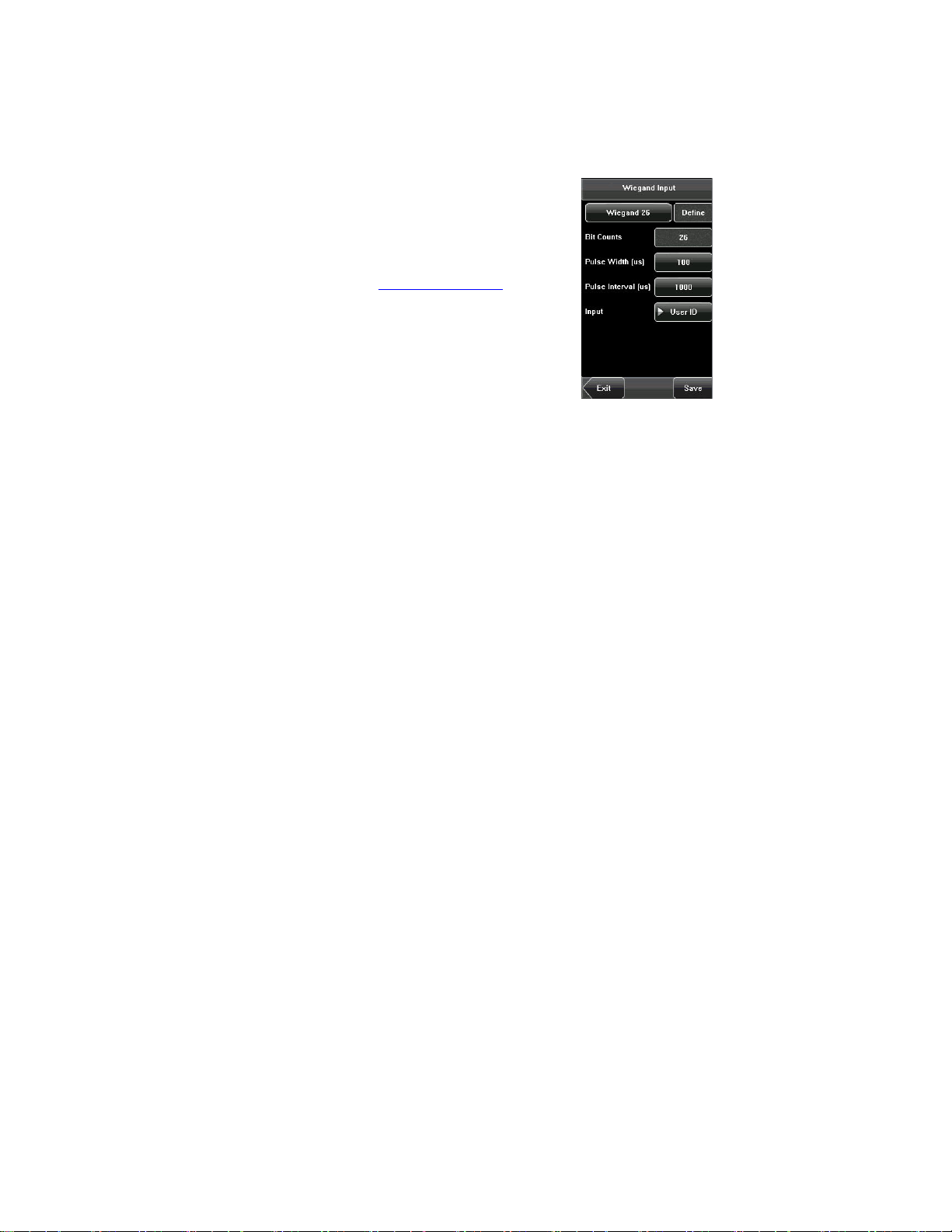
5.4 Wiegand Input
Wiegand Format: The system has two built-in
formats Wiegand 26-bits and Wiegand 34-bits, and
also supports the format customization function to
meet individualized requirements. About the Wiegand
format, please refer to 5.3 Wiegand Output.
Bit counts: Wiegand data digit length.
Pulse width: Pulse width is 100 microseconds by
default, which can be adjusted from 20 to 800.
Pulse interval: It is 900 microseconds by default,
which can adjusted between 200 and 20000.
Input: Content contained in Wiegand input signal, including User ID or card
number.
57
Page 66

3 inches Facial & Fingerprint Recognition Series Product User Manual
6. System Settings
Through the [System] menu, you can set system-related parameters,
including the General, Display, Fingerprint, Face, Log settings, Shortcut
Def, Access Control Set, and Firmware Update, to enable the device to
meet user requirements to the greatest extent in terms of functionality and
display.
58
Page 67

Error! Use the Home tab to apply 标题 1 to the text that you want to appear
here.
6.1 General Parameters
Keyboard Clicks: This parameter is used to set
whether to generate beep sound in response to every
keyboard touch. Select “ON” to enable the beep sound,
and select “OFF” to mute.
Voice Prompts: This parameter is used to set whether
to play voice prompts during the operation of the device.
Select “ON” to enable the voice prompt, and select
“OFF” to mute.
Volume: This parameter is used to adjust the volume of
voice prompts.
59
Page 68

3 inches Facial & Fingerprint Recognition Series Product User Manual
6.2 Interface Parameters
Language: This parameter is used to display the
current language used by the device. For
multilingual-capable devices, you can switch between
different languages through this parameter. Then you
should restart the device.
Too lbar : This parameter is used to display the style
of the shortcut keys on the initial interface. It can be
set to “Auto Hide” and “Permanent Display”. By
selecting “Auto Hide”, you can manually display or
hide the toolbar. By selecting “Permanent Display”,
you can permanently display the toolbar on the initial interface.
Sleep Time (S): This parameter is used to specify a period after which the
device is put in sleep mode if no operation within this period. You can wake
up the device from sleep by pressing any key or touching the screen.
Numerical range in 1 ~ 30 minutes, the factory default for 3 minutes.
60
Page 69

Error! Use the Home tab to apply 标题 1 to the text that you want to appear
here.
6.3 Fingerprint Parameters
1: 1 Threshold: This parameter is used to set the
threshold of matching between the current fingerprint
and the fingerprint template enrolled in the device in
the 1:1 verification mode. If the similarity between the
current fingerprint and the fingerprint template
enrolled in the device is larger than this threshold, the
matching is successful; otherwise, the matching is not
successful.
1: N Threshold: This parameter is used to set the
threshold of matching between the current fingerprint
and the fingerprint template enrolled in the device in the 1: N verification
mode. If the similarity between the current fingerprint and the fingerprint
template enrolled in the device is larger than this threshold, the matching is
successful; otherwise, the matching is not successful.
The recommended thresholds are as follows:
(FRR) (FAR)
1: N 1: 1
Threshold
High Low 45 25
Medium Medium 35 15
Low High 25 10
Fingerprint Image: This parameter is used to set whether to display the
fingerprint image on the screen during fingerprint enrollment or comparison. It
has four options:
Show for Enroll: Display the fingerprint on the screen in enrolling process.
Show for Match: Display the fingerprint on the screen in verification process.
61
Page 70

3 inches Facial & Fingerprint Recognition Series Product User Manual
Always Show: Display the fingerprint on the screen in enrolling and verifying process.
Never Show: Never display the fingerprint on the screen in any case.
62
Page 71

Error! Use the Home tab to apply 标题 1 to the text that you want to appear
here.
6.4 Face Parameters
1: 1 Threshold: This parameter is used to set the
threshold of matching between the current face and
the face template enrolled in the device in the 1:1
verification mode. If the similarity between the current
face and the face template enrolled in the device is
larger than this threshold, the matching is successful;
otherwise, the matching is not successful. The valid
value scope is 70-120. The higher the threshold, the
lower the FAR and the higher the FRR are, and vice
versa.
1: N Threshold: This parameter is used to set the
threshold of matching between the current face and the face template
enrolled in the device in the 1: N verification mode. If the similarity between
the current face and the face template enrolled in the device is larger than
this threshold, the matching is successful; otherwise, the matching is not
successful. The valid value scope is 80-120. The higher the threshold, the
lower the FAR and the higher the FRR are, and vice versa.
The recommended thresholds are as follows:
FRR FAR
High Low 85 80
Medium Medium 82 75
Low High 80 70
Exposure: This parameter is used to set the exposure value of the camera.
Quality: This parameter is used to set a quality threshold for the face images
obtained. The device accepts the face images and processes them by
Threshold
1: N 1:1
63
Page 72

3 inches Facial & Fingerprint Recognition Series Product User Manual
adopting the face algorithm when their quality is higher than the threshold;
otherwise, it filters these face images.
Note: Improper adjustment of the Exposure and Quality parameters may
severely affect the performance of the device. Please adjust the Exposure
parameter only under the guidance of the after-sales service personnel from our
company.
64
Page 73

Error! Use the Home tab to apply 标题 1 to the text that you want to appear
here.
6.5 Log Settings
Log Alert: When the available space is insufficient to
store the specified number of attendance records, the
device will automatically generate an alarm (Value
scope: 1-99).
Dup. Punch Period (m): If a user’s attendance
record already exists and the user punches in again
within the specified period (unit: minute), the second
attendance record will not be stored (Value scope:
1-60 minutes).
Workcode Mode: This parameter is used to select
the work code input mode among Mode 1, Mode 2 and None during
attendance verification. If you select Mode 1, the attendance verification
starts after you input the work code on the initial interface; if you select Mode
2, the attendance verification starts before you input the work code on the
initial interface; if you select None, you do not need to input the work code
during attendance verification on the initial interface. For the input of the work
code, see7.3 Work Code.
Card Only: If this parameter is set to “YES”, you pass the verification only
after card verification. If this parameter is set to “NO”, you need to verify your
face or fingerprint after card verification.
Face interval: According your need to set it. Then default value is o, namely
don’t have interval.
1: G Verify: Select it as YES or NO, namely set whether or not start this
function.
65
Page 74

3 inches Facial & Fingerprint Recognition Series Product User Manual
6.6 Shortcut Definitions
Define touch screen functional shortcut keys. For the device with face
grouping function (MENU--System--Log Settings--1: G Verify), the definition
method of shortcut keys is described as follows:
1.Set shortcut keys
The method to set shortcut keys is described as follows:
(1) Click the Shortcut Def. item to display the list of the existing shortcut keys;
click the shortcut key to modify, as shown in figure 1. Enter the edit screen,
and click Function box, as shown in figure 2. Enter the Function screen, and
the user can select desired settings for the type of the shortcut keys
according to practical needs, such as 1-5 groups of faces(Enable Group
Verify Function), undefined ,status ,workcode and SMS.
(2) The user can set the shortcut key as status key; click the Status, as
shown in figure 3 above; enter the edit screen of the status key, as shown in
figure 1 below; click the Label box, as shown in figure 2 below; enter the
Label screen, as shown in figure 3 below; click the row of the label (six
66
Page 75

Error! Use the Home tab to apply 标题 1 to the text that you want to appear
here.
options for the status) to change it to the corresponding label; the user can
modify the label of the status key according to practical needs.
(3) The Code cannot be modified; it is changed accordingly with the selected
label of the status key. Select Auto switch, and select “On”, as shown in
figure 1 below.
(4) Click the time box after “week”, as shown in figure 2 above, to enter the
time setting screen, as shown in figure 3 above. Click the key on the touch
screen to set the time; click [OK] to save and return to the edit screen.
67
Page 76

3 inches Facial & Fingerprint Recognition Series Product User Manual
(5) After the setting is completed, click [Save] to save the setting and return to
the Shortcut Def. screen.
2. Use shortcut keys
Click
are displayed on the right corner of the interface for use.
on the initial interface, and the related status and function keys
68
Page 77

Error! Use the Home tab to apply 标题 1 to the text that you want to appear
here.
6.7 Access Settings
Access control settings are to set user’s open door
time zone, control lock and set related device
parameters. It is not enabled by factory default, you
can click [MENU]-[System]-[Display]-[Enable access],
select YES or NO.
To unlock, the enrolled user must accord with the
following conditions:
1. The current unlock time should be in the effective
time of the user time zone or group zone.
2. The group where the user is must be in access
control (or in the same access control with other group, to open the door
together).
The new enrolled user is under the first group by default, and use the No. 1
group time zone, the No. 1 access control group. The new enrolled user is in
unlocking state (if you have modified the related settings of access control,
the system will be changed with the modification).
6.7.1 Time zone setting
Time zone is the minimum unit of access control
option. The whole system can define 50 time zones.
Every time zone consists of seven time sections (that
is, one week). Every time section is the effective time
zone within 24 hours every day. Every user can set 3
time zones. It’s “or” between the three zones. It is
effective if only one is satisfied. Every time section
format is HH:MM-HH:MM, namely, accurate to
69
Page 78

3 inches Facial & Fingerprint Recognition Series Product User Manual
minute.
If end time is smaller than start time (23:57- 23:56), the whole day is
forbidden. If end time is bigger than start time (00:00- 23:59), it is effective
section.
Effective time zone for user unlocking: 00:00-23:59 or end time is bigger than
start time.
Notice: System default time zone 1 as whole day open (namely, the
new enrolled user is unlocking).
6.7.2 Holiday setting
Special access control time may be needed during
holidays. It is different to modify everybody’s access
control time. So a holiday access control time can be
set, which is applicable for all employees.
1. Add holiday:
(1) Enter holiday add interface, press the key to edit
the items.
(2) Press the touch screen number key to set the value,
after setting, press [OK] to save, and press [X] for exit
and return to the previous interface.
(3) Press [Save] to save the current information and return to the previous
interface; press [Exit] directly to return to the previous interface without
saving the current information.
70
Page 79

Error! Use the Home tab to apply 标题 1 to the text that you want to appear
here.
2. Edit holiday
Select the holiday to be edited and enter the edit
interface. The edit operation is similar to add holiday.
After editing, press [Save] to save and return to the
previous interface.
Notice: If holiday access control time is set,
user’s open door time zone during holiday is subject
to the time zone here.
3. Delete holiday
Select the holiday to be deleted. Press [Delete] to
popup the confirm interface as follows. Select [Yes]
to delete this holiday, otherwise select [No] to
cancel the operation.
71
Page 80

3 inches Facial & Fingerprint Recognition Series Product User Manual
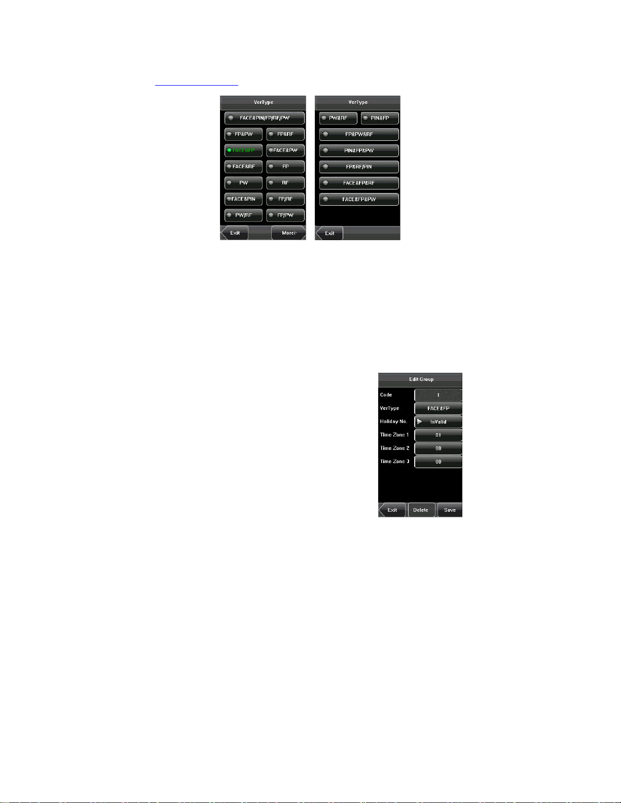
6.7.3 Group time zone setting
Grouping is to manage employees in groups.
Employees in group use group time zone by default.
Group members can also set user time zone. Every
group can hold three time zones. The new enrolled
user belongs to Group 1 by default and can also be
allocated to other groups.
1. Add group time zone
(1) Enter the Add Group interface; press the key to
edit the items.
Code: Enter the number edit interface to set the
value.
VerType: Select the Group Verify Type.
Holiday No.: Select if the Time zone is valid in
holiday.
Time Zone: Select the Group Time Zone.
(2) After editing, press [Save] to save the current information and return to the
previous interface; press [Exit] directly to return to the previous interface
without saving the current information.
Note:
(1) RF means ID card verification. Only the products with the built-in ID card
module support the ID card verification.
(2) For Multi-combination verification, please refer to 12.7 Multi-combination
72
Page 81
Error! Use the Home tab to apply 标题 1 to the text that you want to appear
here.
Authentication Mode.
Notice:
(1) If the holiday is valid, only when there is an intersection between group
zone and holiday time zone, can the group member open the door.
(2) If the holiday is invalid, the access control time of group member won’t be
affected by holiday.
2. Edit group time zone
Press the line to be edited, and enter the edit
interface. After editing, press [Save] to save the
current information and return to the previous
interface; press [Exit] directly to return to the previous
interface without saving the current information.
73
Page 82

3 inches Facial & Fingerprint Recognition Series Product User Manual
3. Delete group time zone
Select the line to be deleted. Press [Delete] to popup
the confirm interface as follows. Select [Yes] to delete
this holiday, otherwise select [No] to cancel the
operation.
6.7.4 Unlock Combination Setting
Make various groups into different access controls to
achieve multi-verification and improve security. An
access control can be made up of 5 groups at most.
1. Add Unlock Combination
(1) Enter holiday add Combination Setting interface,
press the key to edit the items.
(2) Press the touch screen number key to set the
value, after setting, press [OK] to save, and press [X]
for exit and return to the previous interface.
(3) Press [Save] to save the current information and
return to the previous interface; press [Exit] directly to return to the previous
interface without saving the current information.
74
Page 83

Error! Use the Home tab to apply 标题 1 to the text that you want to appear
here.
2. Edit Unlock Combination
Select the line to be edited. Press the item directly to
enter the edit interface. After editing, press [Save] to
save the current information and return to the previous
interface; press [Exit] directly to return to the previous
interface without saving the current information.
3. Delete Unlock Combination
Select the line to be deleted. Press [Delete] to popup
the confirm interface as follows. Select [Yes] to delete
this holiday, otherwise select [No] to cancel the
operation
75
Page 84

3 inches Facial & Fingerprint Recognition Series Product User Manual
6.7.5 Access control parameter
Through the [Access] menu, you can set the
parameters of the electronic locks and related access
control devices.
Lock Delay: Indicates the duration for the device to
place the electric lock in open state. (Value scope:
1-10 seconds)
Door Sensor Delay: Indicates the delay for checking
the door sensor after the door is opened. If door
sensor state is inconsistent with the normal state set
by the door sensor switch, an alarm will be triggered,
and this period of time is regarded as the “door sensor delay”. (Value scope:
1-99 seconds)
Door Sensor Mode: Includes the None, Normally Open (NO), and Normally
Closed (NC) modes. “None” indicates that the door sensor switch is not used.
“NO” indicates that the door sensor is open in the normal state. “NC”
indicates that the door sensor is closed in the normal state.
Alarm Delay: Indicates the duration from the detection of the door sensor
exception to the generation of alarm signal. (Value scope: 1-99 seconds)
Failure Alarm Threshold: When the failed press times reach the set times,
alarm signal will come out (effective value: 1-9 times).
NC Time Zone: Set time zone for access control NC. Nobody can unlock
during this time zone.
NO Time Zone: Set time zone for access control NO. The lock is always in
valid state during this time zone.
Valid in Holiday: Define time zone for NO or NC. Whether the time zone set
in holiday time zone is valid.
76
Page 85

Error! Use the Home tab to apply 标题 1 to the text that you want to appear
here.
Notice:
1. If the Time Zone of normally open or normally closed has been set, please
switch door sensor to no, otherwise it will produce alarm signal during Normal
close Time Zone or Normal open Time Zone.
2. If the normally open or normally closed Time Zone is not defined yet by the
time, the equipment will prompt that you to define the Time Zone, and
transfer you to the Time Zone interface to add.
6.7.6 Duress Alarm Parameters
There are duress alarm parameters setting in the
device. When an employee comes across a duress
situation, he can use the set duress alarm mode to
verify. The device will open the door as usual, but
the alarm signal will be sent to the alarm.
1: 1 Trigger: if select “Yes”, when user use 1: 1
match mode, alarm signal will come out. Or there is
no alarm signal.
1: N Trigger: if select “Yes”, when user use 1: N
match mode, alarm signal will come out. Or there is
no alarm signal.
Password Trigger: If select “Yes”, when a user use password verification
mode, alarm signal will come out. Or there is no alarm signal.
Alarm Delay: After duress alarm gets started, the alarm signal will not output
directly. It can be defined. After the set time period, the alarm signal will be
generated automatically (0-255 seconds).
77
Page 86

3 inches Facial & Fingerprint Recognition Series Product User Manual
6.7.7 Anti-Pass back setting
Set the device Anti-Pass back function.
APB Direction: There are four options: None,
APB-Out, APB-In, APB-Out/In.
Device Status: There are three options: Exit Control,
Entry Control and None.
For Anti-Pass back function, please refer to 12.8
Anti-Pass Back.
Anti-Pass back setting operation:
(1) Enter Anti-Pass back setting interface, press the
key to edit the items.
(2) Press the touch screen number key to set the value, after setting, press
[OK] to save, and press [X] for exit and return to the previous interface.
(3) Press [Save] to save the current information and return to the previous
interface; press [Exit] directly to return to the previous interface without
saving the current information.
78
Page 87

Error! Use the Home tab to apply 标题 1 to the text that you want to appear
here.
6.8 Update
You can upgrade the device firmware by using the upgrade file in the USB
disk through this function.
If you need the firmware upgrade file, please contact our technical
support personnel. Generally the firmware upgrade is not recommended.
79
Page 88

7. Data Management
7. Data Management
Through the [Data Mgt.] menu, you can perform management of data stored
on the device, for example, delete the attendance records, delete all data,
clear administrator, restore the device to factory settings, and query user
records.
Notice: Short message services (SMS) and working number functions
are not standard configuration specifications. They are supported only by
these devices.
Delete Transactions: Delete all the attendance records.
Delete All Data: Delete all the information of enrolled personnel, including
their fingerprints, face images and attendance records.
Clear Administrator: Change all administrators to ordinary users.
Restore to Factory Settings: Restore all parameters on the device to
80
Page 89

Error! Use the Home tab to apply 标题 1 to the text that you want to appear
here.
factory settings.
SMS: Operators can write public or personal short messages and display
them for designated persons at designated time. In addition, operators can
prepare short messages in advance.
Working number: Operators can set one or multiple working numbers for
an employee according to the type of his job. The working numbers can be
used to calculate his attendance and salary.
Notice: The employee information and attendance records will not be
deleted during restoration to factory settings.
81
Page 90

7. Data Management
7.1 Query Record
After check-in successfully, the employee’s attendance records are saved in
the device. You can easily query these attendance records.
User ID: Enter the user ID of the employee to query. If this field is left blank,
you can query the attendance records of all the employees. If you enter a
user ID, you can query the attendance records of this employee.
Query Time Period: Select a time period to query, including the customized
time period, yesterday, this week, last week, this month, last month, and all
time periods.
Start and End: When you select a customized time period, you need to input
a start time and an end time. When you select other options for the time
period, the start and end time will be automatically adjusted to the related
time.
After setting the query conditions, press [Query] and the records that meet
the specified query conditions will be displayed on screen.
Select the row where the desired record is located, you can query the
detailed information of this record.
82
Page 91

Error! Use the Home tab to apply 标题 1 to the text that you want to appear
here.
For example, press User ID and enter the edit interface, input the ID number
and press [Query], the query result will display as below.
83
Page 92

7. Data Management
7.2 SMS
Short messages are similar to announcements and notices. Operators can
write a short message according to the contents to be announced in advance,
and display the short message on the screen during a designated period.
Short messages are classified into public and personal short messages. If a
short message is configured as public, it will be automatically displayed on
the minutes within a designated period; alternatively, users can use the
shortcut keys (can be set in the keyboard definition) to view it. If a short
message is configured as personal, the employee who receives it can view it
after his attendance information is verified.
7.2.1 Set a Short Message
1. Add a short message
a) Select Short Message > Add on the Data Management interface to
enter the interface shown in the following figure:
Start: means the time when the short message takes effect.
Valid: means that the short message is only displayed within a validity
84
Page 93

Error! Use the Home tab to apply 标题 1 to the text that you want to appear
here.
period.
Typ e:
Reserved: means that the short message is prepared in advance but
not configured as personal or public.
Personal: means that the short message can only be read by a specific
person.
Public: means that the short message can be read by all people.
b) As shown in the following figures, click the short message input area,
start the T9 IME, and input SMS contents. For the inputting method, see
the attachment 1 "Operation Description of T9 Inputting Method".".
c) Click Start or Valid to start the configuration interface shown in the
following figures:
85
Page 94

3 inches Facial & Fingerprint Recognition Series Product User Manual
Press the number key to input values to be set, and click OK to save the
settings and return to the previous interface.
d) Click Type to switch the types of a short message, including personal,
public, and reserved. The following figure shows the personal type:
e) Click Hand out SMS to start the Hand out SMS interface. As shown in
the following figures, by clicking the name of an employee, the employee
is Checked and the short message will be handed out to him:
86
Page 95

Error! Use the Home tab to apply 标题 1 to the text that you want to appear
here.
f) As shown in the following figures, click Done to save the settings and
return the previous interface. After that, click Save to store the short
message and goes back to the previous interface. Then the new short
message is displayed on the interface.
2. Edit a short message
Click the message to be edited in the SMS interface.
The procedure of editing a short message is the same as that of adding
87
Page 96

3 inches Facial & Fingerprint Recognition Series Product User Manual
a short message.
3. Delete a short message
By clicking Delete on the Edit interface, the short message to be
deleted is removed. In addition, any information related to the message
is deleted at the same time.
7.2.2 View a Short Message
View a public short message
On the initial interface, public short messages are automatically
displayed on the minutes Alternatively, the public short messages can
be viewed by clicking the shortcut keys on the interface, as shown in the
following figures. For detailed setting methods, see 6.6 Shortcut
Definitions.
88
Page 97

Error! Use the Home tab to apply 标题 1 to the text that you want to appear
here.
After the viewing is finished, click Return to exit the View interface and
return the initial interface.
View a personal short message
After a user is authorized, his short message will be displayed, as
shown in the following figure:
89
Page 98

3 inches Facial & Fingerprint Recognition Series Product User Manual
7.3 Work Code
Easy for users quickly deal with data of distinguish different situation. Please
click [System]--[Shortcut Definitions]--[Undefine], select [Workcode] and
save, can opening working code function. For detail operation in [Data
Management]--[Workcode]. Can edit, add, delete and query.
7.3.1 Add a work code
1. Press [Add] on the WorkCode interface to display the [Add] interface as
figures below:
No.: A digital code of the work code.
Label: The meaning of the work code.
2. Press the corresponding entry button of [No.] on the [Add] interface display
the No. entry interface. On this interface, enter a No.
3. Press the corresponding entry button of [Label] on the Workacode
interface to display the text entry interface. On this interface, enter a label of
work code. (See 12.1 T9 Input Instructions)
90
Page 99

Error! Use the Home tab to apply 标题 1 to the text that you want to appear
here.
7.3.2 Edit and delete a work code
1. Press the row of a work code on the WorkCode interface to display the
[Edit] interface.
2. To edit this work code, enter a new No. and label with the same operation
steps as described in “Add a work code”.
3. To delete this work code, press [Delete].
4. On the displayed prompt interface, press <YES> to confirm the deletion of
this work code, and press <NO> to cancel the deletion operation.
7.3.3. Edit and delete a work code
Press [Delete] on the WorkCode interface, display the keyboard interface,
prompt you want to query code, to enter the Number, and then click OK.
91
Page 100

3 inches Facial & Fingerprint Recognition Series Product User Manual
8. Date/Time Setting
8.1 Set Date/Time
The date and time of the device must be set
accurately to ensure the accuracy of attendance time.
1. Press [Menu] on the initial interface to display the
main menu interface.
2. Press [Time/Date] on the main menu interface to
display the time setting interface.
3. Select the desired date and time by pressing the
parameter. For the time format, there are 10 formats
to select from. Both 12-hour and 24-hour time
systems are supported.
4. Press [Save] to save the current information and return to the previous
interface. Press [Exit] to return to the previous interface without saving the
current information.
92
 Loading...