

Page 1
Finger Vein Access Control dvice
Quick Start Guide
Version: 1.0 Date: June 2015
1 Overview
Fingerprint & Finger Vein Device
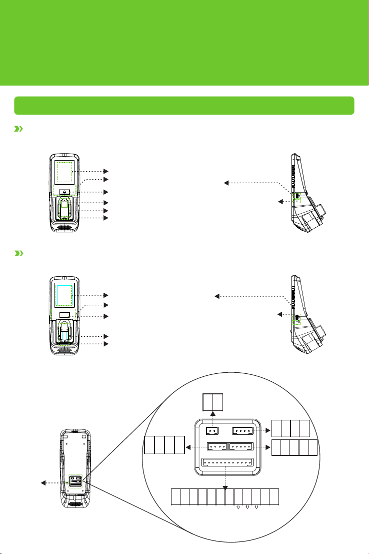
Front
Finger Vein Device
Front
Touch s creen
Car d reader
Doo rbell
Fing erpr int read er
Fing er vein r eader
Fing er vein s ensor : Duri ng
reg istra tion, a fter fi nger
tou ches th e senso r, devic e
beg ins col lecti ng and ve rifyi ng
fin gerpr int and f inger v ein.
USB s lot
Res et butt on: Pres s the but ton
(wi th shar p-hea ded too l with le ss
tha n 2 mm in dia meter ) after 3 0sec ond pow ering -on to re set
dev ice.
Lef t Side:
Lef t Side
Rese
Back
Tamp er
Ala rm
Swi tch
Touch screen
Card reader
Doorb ell
Finger v ein reader
Fing er vein s ensor : Duri ng regis trati on,
aft er fing er touc hes the s ensor, d evice
beg ins col lecti ng and ve rifyi ng fing er
vei n.
}
Powe r Outpu t
USB s lot
Res et butt on: Pres s the but ton (wi th
sha rp-he aded to ol with l ess tha n 2
mm in d iamet er) aft er 30-s econd
pow ering -on to re set dev ice.
Powe r Input
Wie gand
Inp ut
}
12 V
GN D
IW D0
IW D1
Aux iliar y
Inp ut
}
AU X
GN D
BE LL-
}
Doo rbell
1
}
+1 2V
GN D
Doo r senso r
}
BE LL +
SE N
}
Open /Clos e
-doo r butto n
Eth ernet
}
RJ 45 -1
RJ 45 -2
RJ 45 -3
RJ 45 -6
WD 0
WD 1
GN D
48 5A
}
RS4 85
48 5B
}
Wie gand
Out put
Ala rm
}
GN D
BU T
NO 1
CO M1
NC 1
AL-
NO
AL +
NC
Comm on
}
Loc k
Page 2
2 Cautions
①Shut down the power d uring ins talla tion.
② 12V/3A power supply is rec ommended.
③Do not in stall t he device in a place s ubject
to di rect sunlight or h umidi ty.
④Ple ase follow the connec tor instruction for
wirin g.
⑤ Under seriou s electrostati c environment,
please conne ct the GND before other
wirin gs, in order to prevent stat ic elec tricity
fro m damag ing the d evice.
⑥ It is necessary to con nect the FR 107 diodes
in parallel to the posi tive and negat ive pol es
of the electrica l lock, so as t o release the
self-induc tance
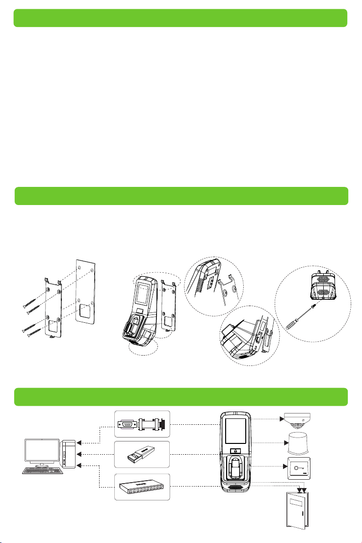
3 Installation on Wall
Insert cables to connecto rs befo re installat ion.
①Put the moun ting te mplat e stick er onto the
wall, and dr ill holes a ccording to the symbo ls.
②Fix the ba ck plate onto th e wall.
EMF generated when th e lock is t urned
ON/OFF.
⑦ Ple ase pro perly set finger print and f inger
vei n verification m ode before registering
users. Requirement varie s with different
ver ificati on mode s:
» Finger pr int & Finger Vein Mode : Both
fingerprint and finge r vein mu st be ver ified
to ac cess.
» Finger pr int or Finge r Vein Mod e: Only
fingerprint or finger vein is required to be
ver ified to access.
⑧the functions mention ed with a re only
featured with par ticular m odels of device.
③ Install the devi ce onto t he back
plate.
④Fix the de vice with locking sc rews on to
the back plate.
A
A
B
C
B
Bot tom
Vie w
Bac k
Pla te
Mou nting
Tem plate
Note: For user he ights bet ween 15 0CM to 17 0CM, it i s recom mended to install the dev ice
at 140CM above ground (may be modif ied acc ordin g to user average heigh t).
4 Access Control System Diagram
RS485
Ser ver
RS4 85
USB D rive
TCP/ IP
Loc k
2
C
Sir en
Ala rm
Ope n/Clo se
-do or butt on
Doo r Senso r
Doo r
Page 3
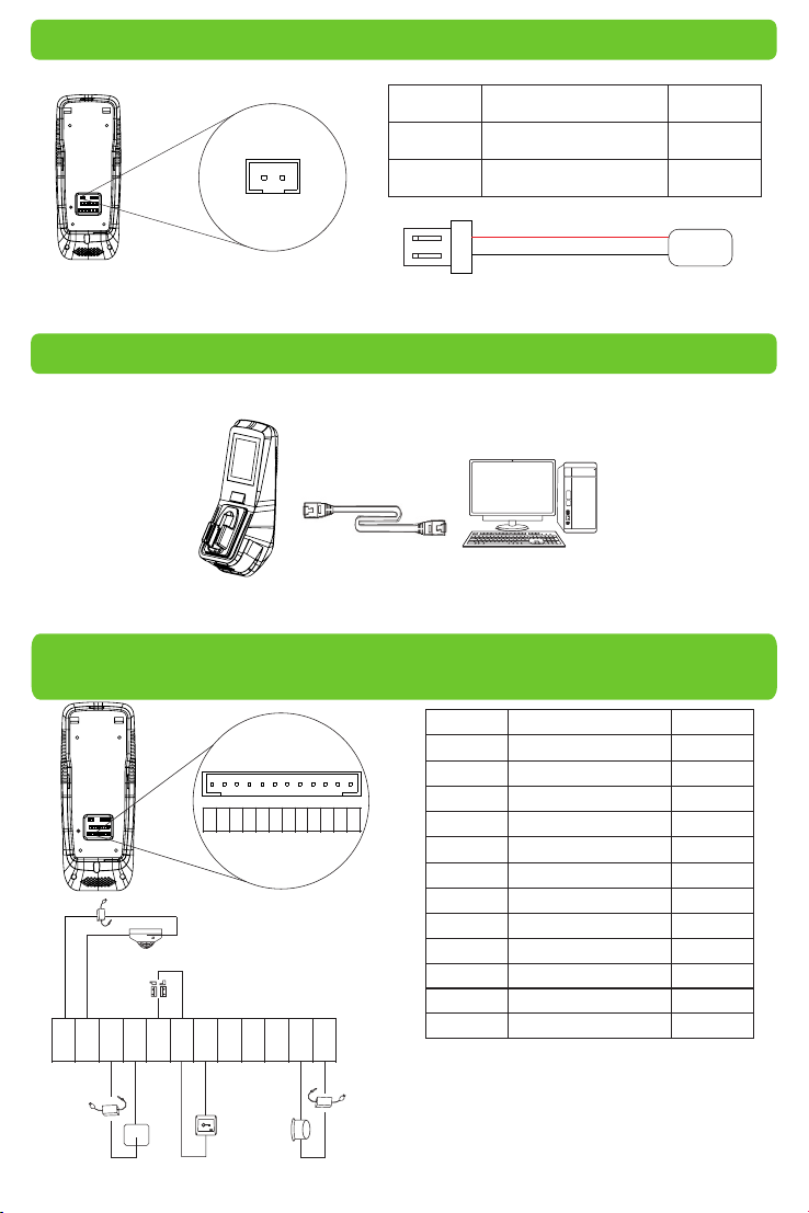
5 Power Connection
+12 V GND
PIN Slot Col or
Power Input +12V
1
2
Ground GND
Red
Black
1
2
+12 V DC
GND
The operation power of the dev ice sha ll be DC12V, the current sha ll be 3A.
6 Connection to Computer softwares via Ethernet
Con nection b etween de vice an d computer (Access co ntrol software) via Eth ernet. Shown
as below:
IP Ad dress: 192. 168. 1.39
IP Ad dress: 192. 168. 1.201
Subnet Mask: 255 .255. 255. 0
Subnet Mask: 255 .255. 255. 0
7 Connection to Doorbell, Door Sensor,
Open/Close Door Button, Alarm & Siren etc.
Slo t
Aux iliar y Inpu t AUX
Gro und GND
Doo rbell B ELL-
Doo rbell B ELL+
Doo r Senso r SEN
Gro und GND
Ope n/Clo se
Doo r Butto n BUT
Nor mal Ope n NO1
Com mon COM1
Norm al Close d NC1
Ala rm AL-
Ala rm AL+
Col or
Bro wn
Pur ple
Gre en
Ora nge
Yell ow
Red
Blu e
Whi te
bla ck
Gre y
Bla ck
Red
AU X
Powe r
+
GN D
Powe r
-
Doo r
Sen sor
BE LL-
-
+
PIN
1
2
3
GND
AUX
BEL L-
SEN
BEL L+
COM 1
GND
NO1
NC1
BUT
AL-
AL+
+
-
Sir en
BE LL +
%
+
-
SE N
Doo
rbe ll
BU T
GN D
Ope n/Clo se
Doo r Butto n
NO 1
CO M1
Ala rm
AL -
NC 1
AL +
+
-
-
Powe r
+
4
5
6
7
8
9
10
11
12
Devic e can be connected v ia Auxiliary
Input Slot with output sw itch si gnal se nsors
including si ren, gas detec tor, inf rared d etector
and emergenc y switch.
3
Page 4

8 Wiegand Input/Output Wiring Instruction
PIN
1
2
3
4
48 5B
48 5A
WD 0
WD 1
12 V
GN D
IW D0
IW D1
GN D
5
6
7
8
9
Slot
Powe r Outpu t +12V
Gro und GND
Wie gand In put IWD 0
Wie gand In put IWD 1
Wie gand Ou tput WD0
Wie gand Ou tput WD 1
Gro und GND
RS4 85 485A
RS4 85 485B
Col or
Red
Bla ck
Whi te
Gre en
Blu e
Yell ow
Bla ck
Gre y
Pur ple
Wie gand Inpu t: the device is featured with Wiegand signal input func tion to connect to c ard
rea der or st andalone devic e.
Wie gand Output: the device i s featu red with stand ard Wiegand signal out put fun ction and
can be used as reader. The wiring di stance between d evice to controller should not exceed 5m
(if longer con nection distan ce or connection with strong inter ference are necessary, please
adopt Wiegand s ignal exteneder).
9 Finger Vein & Fingerprint Registration and Verification Modes
Note: I n finger vein registration p rocess, the fingerp rint of the s elected finger i s also registered.
1. Suggested finger : first fin ger,
middle finge r
3. Ver ification Steps
2. Finge r Place ment Position
①In or der to re ad your
fin gerpr int and f inger v ein
dat a, touc h the fro nt side
of fi nger ve in read er with
fin gert ip,
②The d evice s tart s
col lecti ng data o nce the
fin ger roo t touch es the
fin ger vei n reade r.
①
Fi ng er pr int Re ade r
Fing er Vein Re ader
②
Fing er Guid e
Touch S enso r
①
Touch t he fron t side of f inger v ein
rea der wit h finge rtip, t hen pre ss your
fin ger upo n the fin ger vei n reade r.
②
Touch t he read er with f inger r oot.
Pla ce the fi nger
acc ordin g to the
fin ger gui de.
4
Fing er-ti p must to uch the f ront of f inger
vei n reade r in order t o prope rly col lect
fin gerpr int and f inger v ein ima ges.
Imp roper p ositi oning o f finge r will
aff ect the p roper c ollec tion of
fin gerpr int and f inger v ein ima ges.
Page 5

③
The d evice s tart s colle cting d ata onc e the fin ger roo t touche s the fin ger vei n reade r. Remov e finge r
aft er “be ep” soun d appea rs.
» Maint ain the n atural hand gest ure.
» Do not be nd your finger s.
» Do not exert finge r to press the reader.
10 Main Menu
In the initial inter face, c lick Menu icon
to en ter Main Me nu. Cli ck Scro ll icon
to sc roll down to display full menu. Click
Scroll icon again to scroll up.
11 Ethernet Setting
In the Main M enu, Cl ick “Co mm”>”Ethernet” to enter Ethe rnet Sett ing.
IP Ad dress: the def ault IP addres s is 192.168.1.2 01.
Subnet Mask: the d efault subnet mask is 255 .255.255.0.
Gatew ay : the default gate way is0 .0.0.0.
DNS: the defau lt DNS ad dress i s 0.0.0 .0.
TCP COMM. Por t: the defa ult por t is 4370.
DHCP: D ynami c Host Co nfiguration Protocol, which i s to dyna mically alloca te IP add resses for
client via ser ver. If DHCP is enabled, IP cann ot be set m anually.
Display in Status Bar : To enable or dis able displaying Netwo rk Connec tion Ic on in Status Bar.
12 System Setting
?
Click “System” in Main Menu to e nter System Se tting.
5
Page 6

Date Time: To set date & time.
Acc ess Logs Setti ng★: To set Access Log parameters
accordin g to pers onal needs.
FV&FP Pa rameters: To set finger vein par amete rs acco rding to
personal nee ds.
Reset: To reset devic e and system to fa ctor y setti ngs.
USB Upgrade: To upgrade devi ce's fi rmware program through
Upgrade documents in USB.
Note: User messages a nd sett ings of Access Control inter face
are n ot dele ted after being reset to factory setting.
13 Access Control Management
Click “Acce ss Cont rol” in Mai n Menu to enter Ac cess Co ntrol M anagement interface.
Users can open l ocks on ly upon these re quire ments are met:
1.The access time shoul d fall in to eith er the use's indiv idual t ime zon e or group time zone.
2.User's gro up must b e in the access comb o (when t here are other grou ps in the s ame access
combo, ver ifica tion of members of t hose groups is also required to unl ock the door).
Acc ess Con trol Options : To set Locks and related devices'
parameters.
Tim e Rule Sett ing: To set maximum 50 time rules. Each tim e
rules consis ts of 7 spa ces, ea ch spac e consists of 3 time s lots.
Holidays: to set holiday access con trol and acces s time.
Com bined Verification: To set acce ss cont rol com binations.
A combinatio n consi st of maximum 5 acce ss cont rol groups.
Anti-passb ack Setup: To prevent passing back whic h causes
risks to secur it y. Once enabled, entr y and exit records must
be matched in order t o open door. Entry anti -passback, exit
passback and e ntry & exit ant i-pas sback functions are
ava ilable.
Acc ess Con trol Combination Setting
Note: ①You may choose n ot to use r Access3.5 So ft ware an d to set ac cess control c ombinations
directly in de vice when using the devic e for the first ti me.
② If you us e Access3.5 So ft ware to set Access Control Combination of the devic e, you are
then not allowed to s et access control combinatio ns directly in device.
E.g.: Add an access c ontrol combi nation which required 2 pers ons' ve rificat ion from both group 1
(set in User Man agement) and group 2.
1. In “Combi ned Verificat ion” Lis t, click
the desire d combination to modify,
and enter the interface ( shown in 1).
2.Click “+” to ascen d, click “-“ to
descend to set user group no., and
click “Confirm” to save an d back to
“Co mbined Verification”.
6
Page 7

Note: ① A single Access Control Combinat ion can consist of maximu m 5 user groups (in order to
open door, both 5 users' verifications are re quired).
②If the co mbination is set a s shown i n 3, a user f rom group 2 must obtain verifi cations of 2
users from g roup 1 in order to open door.
③Set all grou p no. to zero to rese t acces s control comb ination.
14 Add Users
In Main Men u inter face, click “User Mgt.” -> “New User” to enter “Ne w User.”
User ID: to insert u ser ID (1 - 9 digit s).
Name: to set user name (1 -24 chc aractes ; a Chine se
character eq uals two characters).
User Role: to se t user' s authori ty. U sers are defau lt set as
ord inary users a nd can be m odified to Adm in. Users are
only allowed to be ve rified by finger vein, fingerprint,
card or pass word, while Admin s are aut horized to ent er
Main Menu apart from normal v erification fu nctions.
FV&FP: to regis ter fin ger vei n and fingerprint.
Suggested to register first fin ger and m iddle finger. See
9. Finge r Vein & Fingerprint Registration an d Verificatio n
Modes for re ference.
Badge Number«: to register card no..
Passwo rd: to register user password (1-8 digits).
Acc ess Con trol Ro le: to se t users' access
control au thority.
15 User Verification
Note: the device is by de fault s et as “Finge rprint & Finge r Vein Mod e”, and ca n be modified to
“Finge rprint or Fing er Vein Mo de”. See 7.3 Fi nger Vein & Fingerpr int Parameters Setting in
Acc ess Con trol Finger Vein S eries Use r Manual.
» Finger pr int & Finger Vein Mode : Fingerprint+Finger Vein ve rification to success.
» : Fingerprint or Fi nger Vein verif icati on to suc cess.Finger pr int or Finge r Vein Mod e
Finger Vein & Fingerprint Ver ifica tion
Pla ce and press fin ger on the reade r
pro perly. “Su ccessfully ver ified ” appears
upon success ful ver ification.
Card Verificatio n
Swipe card i n swiping area . “Successfully
ver ified” appears upo n successful verifica tion.
7
Page 8

Passwo rd Ver ification
①Click K eypad Icon in the in itial i nterface to enter User ID inter face.
②Enter User ID and click O K, t hen selec t pass ve rification mod e (show n in 4).
③ Enter password an d click O K. “Successfully verified” appears upon s ucces sful ve rificat ion.
16 Data Management
In Main Men u inter face, click “Data Mgt” to enter D ata Management i nterface.
Delete Data: to manag e device data, includin g deleting all data, dele ting
all manageme nt auth orities, deleting all p romotional d isplay and
res ettin g to factor y setting.
Backu p Data: t o back up d evice ope ratio n data and relat ed data t o
computer or Hard Dr ive.
Restore Da ta: to restore data saved in Computer or Hard Drive to the
device.
Ple ase refer to Access Control Finger Vein Seires User M anual.
17 Obtain Access Control Report
①Con nect device to network .
②Begin access control devic e opera tion (e.g. Access 3.5)
③Add d evice to the access control soft ware to o btain device dat a and eve nt logs, check
access control events, a nd generate re ports.
Note: Plea se refer to th e attached Acc ess3.5 Access Control Management System User
Manua l CD.
18 Troubleshooting
①“Invalid tim e zone” is displaye d after verifica tion
» Con tact Administr ator to check if t he user h as the priv ilege to gain access within that t ime
zon e.
16 禁用宣传图片
②Verifica tion su cceeds but the use r canno t gain access
» Check whethe r the use r privile ge is set c orrectl y
» Check whethe r the loc k wiring is c orrec t
③The Tamper Alarm rings
» To cancel the triggered ala rm mode, caref ully inspect whe ther the device is p roper ly
installed, and re install the devi ce properly if necessar y.
8
 Loading...