


CEILING FANS
INSTALLATION INSTRUCTION
READ AND SAVE THESE INSTRUCTIONS

SAFETY PRECAUTIONS
Before beginning installation of your new ceiling fan, read and follow these safety precautions. If
you are not familiar with national and local electrical codes and basic electrical wiring procedures,
we recommend that you have a qualified electrician install your new ceiling fan.
Before you begin, TURN OFF THE ELECTRICITY. Determine which circuit your new fan
will be using and remove the fuse or turn off the circuit breaker at the main electrical
panel.
Make sure that all wiring conforms to national and local electrical codes. If you are in
question, obtain a copy of the codes and wire the fan accordingly. Never leave bare
wires uncovered (wire connection), use wire nuts to cap all connections. Plastic electrical tape is not recommended.
When working with electricity, never take short cuts. Follow the code in every respect.
Basic requirements for a ceiling fan installed with lights are, 120 volts AC - 60Hz, on a
grounded circuit with a 15 amp breaker or fuse. Make sure that your electrical system
and choice of location meet these requirements.
If the location where you plan to install your fan does not already have an electrical
outlet, hire a licensed electrician to run the wiring and install an outlet box designed
for ceiling fans or heavy fixtures. The outlet box should be able to support a minimum moving weight of 50 pounds and marked “Acceptable for Fan Support” (Plastic
outlet boxes are not recommended for ceiling fan installation).
If you plan to use an existing electrical location, check to make sure that the outlet box
is not PLASTIC, that it is securely attached and able to support at least 50 pounds of
moving weight and marked “Acceptable for Fan Support”. If you have any questions,
outlet boxes and support systems for ceiling fans are available at most hardware and
do-it-yourself centers. In most cases, your dealer will have all the necessary products
for the proper and safe installation of your ceiling fan.
The location you choose should have a minimum clearance of 20 inches from any wall
to the blade tip at any point in its rotation and a minimum of 7 feet from blade level to
floor and 10 inches from the blades.
1

This ceiling fan was not designed for installation in any location where it might be exposed to
moisture or high humidity. Installation in this type of location could be UNSAFE, will most
likely damage the fan and its finish... and will VOID YOUR WARRANTY.
Every effort has been made to provide you with proper instructions for the safe installation of
this ceiling fan. You could however, encounter situations or problems not covered in this
manual. Should this occur, please refer to a do-it-yourself wiring handbook or hire a qualified
electrician to install your fan.
Never attach the blades to your ceiling fan before the fan body is properly mounted on the
ceiling.
Lubrication of your new ceiling fan is not necessary. The ball bearings have been adequately
charged with grease and permanently sealed at the factory so that, under normal conditions,
further attention is not necessary.
To reduce the risk of fire, electrical shock, or personal injury, mount this fan to
an outlet box marked “Acceptable for Fan Support” and use the Mounting
Screws provided with the outlet box. CAUTION: Install the primary mounting
WARNING
means and use only the hardware provided with the fan.
WARNING
WARNING
To reduce the risk of personal injury take care not to bend the blade carriers.
Be careful not to insert foreign objects into rotating fan blades.
The important safeguards and instructions appearing in this manual are not
meant to cover all possible conditions and situations that may occur. It must be
understood that common sense, caution and careful attention to detail are
factors which cannot be built into this product. These factors must be supplied
by the person or persons installing, caring for, and operating the unit.
Look at Me!
I have safety Tips and
Ideas for installation
These instructions are designed for a number of similar but different ceiling fans. As you
proceed, some steps may or may not apply to the fan you purchased. Compare each
step or optional procedure to your fan and proceed accordingly.
2

PREPARING FOR INSTALLATION
Unpack the carton and inspect the fan
1.
carefully to be sure all contents are
included. Please kindly keep well with
the screws washers and all the other
small items in case of missing. Turn off
power at fuse box to avoid possible
electrical shock.
Use metal outlet box suitable for fan
2.
Phillips
+
Screwdriver
Flat Blade
-
Screwdriver
support (must support 35 lbs). Before
attaching fan to outlet box, ensure the
outlet box is securely fastened by at
least two points to a structural ceiling
member (a loose box will cause the fan
to wobble).
TOOLS NEEDED3.
Wire
Stripper
Step
Ladder
3

INSTALL MOUNTING BRACKET
Install the mounting bracket onto the
1.
electrical junction box in the ceiling
Junction Box
using two machine screws, two washers and two lock washers.
The mounting bracket has slotted
2.
holes to enable it to move sideways
for proper alignment. Make sure the
mounting bracket is centered over the
electrical junction box and that it is
Slotted
Ceiling Canopy Mounting Screw
securely attached. Pull the electrical
wires in the junction box down and
through the mounting bracket. Loosen
the two canopy mounting screws on
the downside face of the mounting
bracket. Back them out about half
way. This will allow for easier installation of the ceiling canopy later.
Note: Angle mount best suited for
3.
angled or vaulted ceilings. A longer
downrod is sometimes necessary to
ensure proper blade clearance.
Ensure the ceiling angle is not
steeper than 16 degrees. Hanger
opening must be facing up-side.
NO MOVEMENT SHOULD OCCUR BETWEEN
THE MOUNTING BRACKET AND THE
ELECTRICAL JUNCTION BOX.
4

DOWNROD PREPARATION
Remove clamp pin (1) and cross pin
1.
(2) from downrod (3).
3
1
Loosen set screws in downrod coupling. Insert down rod through the canopy
2.
and coupling cover (4) as shown above. Insert motor wires through the down
rod and insert the down rod into the down rod coupling. Make sure to align the
hole in the downrod with the hole in the downrod coupling. Install cross pin (1)
removed in step 6 through coupling and downrod. Insert keeper pin (2) into
cross pin until it snaps into place. Tighten set screws (3) in coupling. Slide
coupling cover (4) and canopy onto the downrod above the coupling cover.
2
2
3
1
3.
4
5

HANGING THE FAN BODY
Notice the half ball on the end of
Mounting Bracket
Keyway Pin
Ball Hanger
1.
the support rod is grooved down
one side. This keyway fits over the
small keyway pin on the inside of
the mounting bracket and keeps
the ceiling fan from spinning on the
Support Rod
Ball Hanger
Support Rod
Mounting
Bracket
Keyway Pin
mounting bracket.
Using your step ladder, lift the fan
2.
and place the half ball in the center
of the mounting bracket with the
keyway pin inserted into the
keyway on the ball. Turn the fan
left and right slightly to make sure
it is seated on the bracket with the
keyway pin in the keyway.
Trim the lead wires, leaving
3.
about six inches of each wire
Ball Hanger
extending from the support
rod.
Ground Wire
Support Rod
6

WIRE CONNECTION
Black (hot/power)
White (neutral)
Bare/Green
(ground)
Whit
e
Whit
e
Blac
k
Blue
Blue
Blac
k
Green
Gree
n
Use wire connnectors to connect
1.
household supply and receiver wires
according to the diagram and the
following steps:
White
Black
Receiver
WARNING: Do not wire the fan
motor to a variable-speed (dimmer)
wall control.
• Connect the green wire from the
downrod and mounting bracket to
the Bare/Green (ground) supply
wire.
• Connect the Blue wire with the
white label to the blue fan wire.
• Connect the Black wire with the
white label to the black fan wire.
• Connect the White wire with the
white label to the white fan wire.
• Connect the Black wire with the red
label to the Black (live) supply wire.
• Connect the White wire with the
red label to the White (neutral)
Mounting Bracket
Canopy
Canopy Screw
supply wire.
Lift the ceiling canopy up into place
2.
covering the mounting bracket.
Push the cannopy up so the screws
come through the mounting holes in
in the cannopy. Rotate the canopy
slightly and tighten the screws.
Please refer to page 9 for remote controller
and receiver installation and operation detail.
7
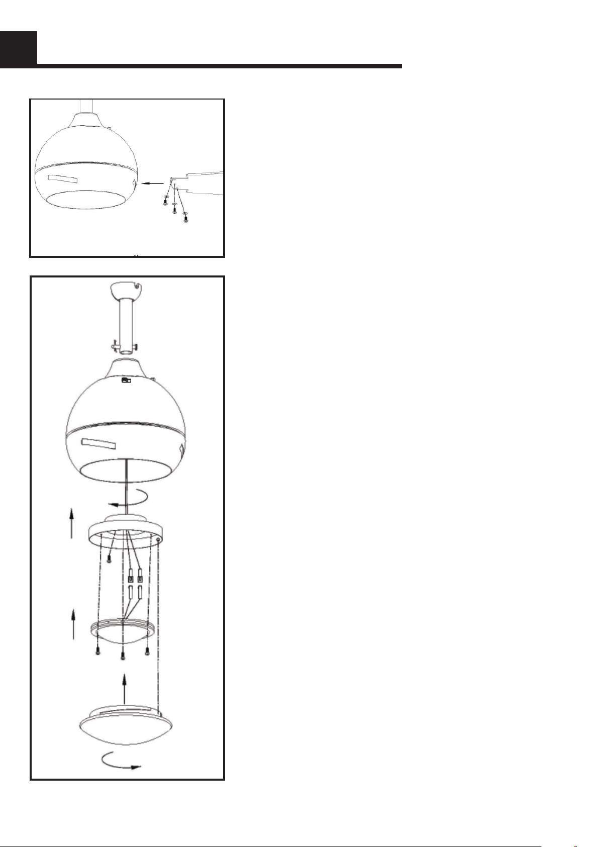
BLADES INSTALLATION
Insert the blades into the center band,
1.
align the holes of blade and the hole of
blade bracket. Tighten them with screws
and washers provided. Kindly Remind:
Extra screws and washers were supplied
for missing in case, but still suggest you
to keep all screws and washers and other
small part well and keep away from
CHILDREN. There are 5 holes on the
blade but only need to lock 3 holes.
Always ensure that fan is set to "OFF"
2.
and blades are still prior to changing
directions. Reverse switch on fan should
ideally be set on "FORWARD" (LEFT
position) during hot seasons to move
blades in an anticlockwise direction &
"REVERSE" (RIGHT position) in cold
seasons to make the fan rotate in clockwise direction.
Remove 1 screw from the connection plate,
3.
then point the keyhole of the lamp plate at
the other 3 screws, put it on, turn counterclockwise, and then take off the screws to
re-lock, finally lock the other 3 screws. Align
the 3 holes on LED with the 3 holes on the
lamp plate and tighten it with screws. Align
the glass notch with the convex point of the
lamp plate, put it on, turn clockwise and
secure it . Locate slots on glass shade and
align with dimples on glass fitter plate. Slide
onto glass fitter plate and turn in a clockwise
direction until it locks into place.
8

REMOTE INSTALLATION
Power Parameters Table
FAN 1.25A FOR FAN
110-130V ON/OFF 150W
Please keep the wire OUTSIDE the bracket to connect
other wires when put the receiver into the bracket.
9

PARTS INVENTORY
Hanging Bracket
Receiver of Remote Control
Canopy
4 in & 6 in Downrods
Yoke Cover
Motor Assembly
Light Kit plate
LED Light
Blade x3
Glass Shade
10

PROBLEM SOLUTION
1. Fan will not start:
Check circuit fuses or breakers.
1.
Check all electrical connections to insure proper
2.
contact.CAUTION: Make sure the main power if OFF when checking any
electrical connection.
2. Fan sounds noisy:
1.
Make sure all motor housing screws are sung.
2.
Make sure the screws that attach the fan blade brackets to the motor are tight.
3.
Make sure wire nut connections are not rubbing against each other or the
interior wall of the switch housing. CAUTION: Make sure main power is off.
4.
Allow a 24-hour "breaking-in" period. Most noise associated with a new fan
disappear during this time.
5.
If using an optional light kit, make sure the screws securing the glassware are
tight. Make sure the light bulbs are not touchingany other component.
3. Fan wobble:
1.
Check that all blade and blade arm screws are secure.
2.
Most fan wobbling problems are caused by blade levels unequal. Check this
level by selecting a point on the ceiling above the tip of one of the blades.
3.
Measure this distance. Rotate the fan until the next blade is positioned for
measurement. Repeat for each blade. This distance deviation should be
equal within 1/8".
4.
Use the enclosed Blade Balancing Kit if the blade wobble is still noticeable.
If the blade wobble is still noticeable, interchanging two adjacent ( side by
side) blades can reditribute the weight and possibly result in smoother
operation.
11
 Loading...