

Page 1
IMPORTANT : PLEASE READ INSTRUCTION BEFORE STARTING THE ASSEMBLY.
ASSEMBLY INSTRUCTION
Thank you for purchasing this quality product. Be sure to check all packing material carefully for small parts which may
have come loose inside the carton during shipment. Separate, identify and count all parts and hardware. Compare with
the parts list to be sure all parts are present.
"DO NOT TIGHTEN SCREWS UNTIL COMPLETELY ASSEMBLED"
"DO NOT OVERTIGHT ANY HARDWARE"
WARNING : SMALL PARTS AND HARDWARE NOT FOR CHILDREN UNDER 3 YEARS. ADULT ASSEMBLY REQUIRED.
HARDWARES LIST
PARTS LIST
PARTS' LOCATION
ASSEMBLY STEPS
ASSEMBLY COMPLETED
TABLE OF CONTENTS
PAGE 2 - 3
PAGE 3 - 4
PAGE 5
PAGE 6 - 17
PAGE 17
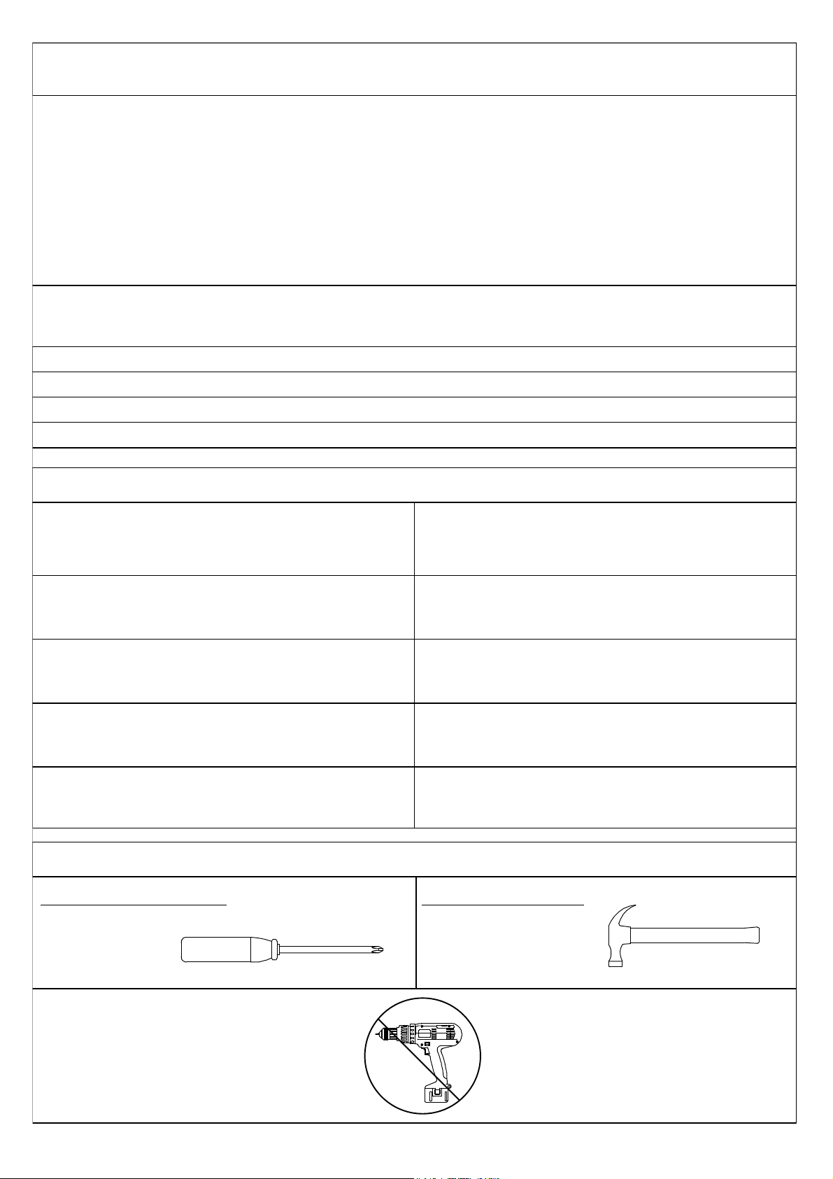
ASSEMBLY TOOLS REQUIRED
1. Screwdriver (not provide)
Skip the power trip this time.
2. Hammer (not provide)
Page 2
ASSEMBLY INSTRUCTION
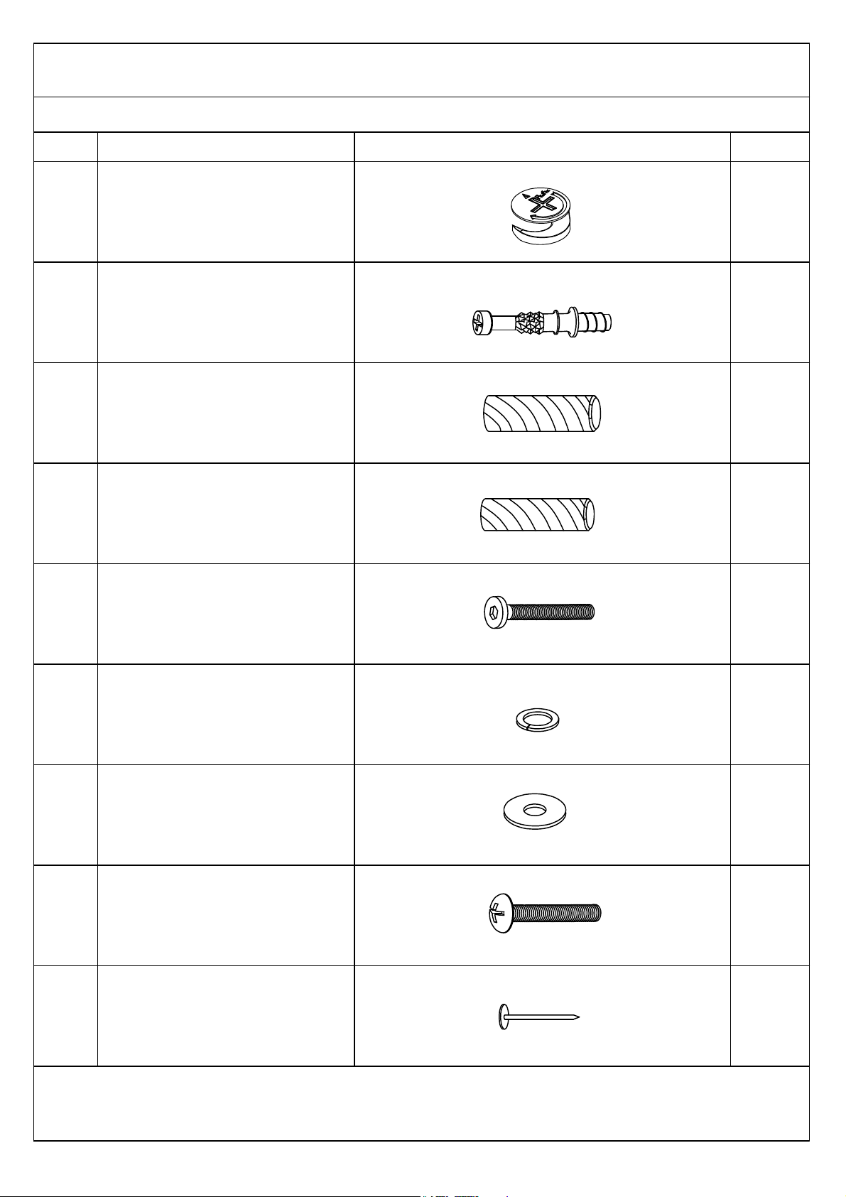
ITEM
A
B
C
D
E
F
G
I
L
DESCRIPTION
MINIFIX CAM LOCK
MINIFIX CAM BOLT
WOOD DOWEL (M8 x 25MM)
WOOD DOWEL (M6 x 25MM)
JCBC SCREW M6 x 35MM
SPRING WASHER M6 x 13MM
FLAT WASHER M6 x 19MM
TRUSS M-SCREW (20MM)
6/8" NAIL
QTY
24 PCS
24 PCS
22 PCS
24 PCS
4 PCS
4 PCS
4 PCS
4 PCS
16 PCS
DRAWING
HARDWARES LIST
MORE HARDWARES DETAIL IN NEXT PAGE...
Page 3
ASSEMBLY INSTRUCTION
HARDWARES LIST
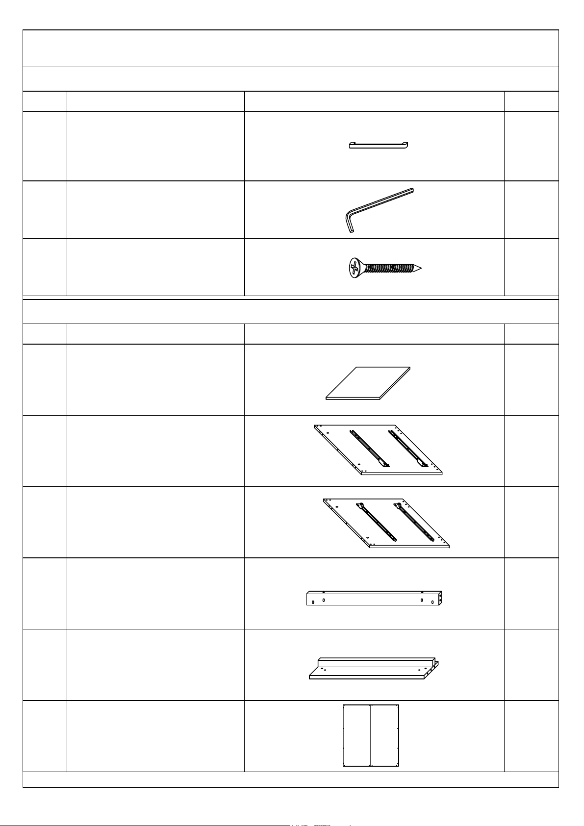
ITEM
M
N
O
DESCRIPTION
HANDLE
M4 ALLEN KEY (65MM)
CSK C/B SCREW (M4 x 25MM)
QTY
2 PCS
1 PC
4 PCS
DRAWING
MORE PARTS DETAIL IN NEXT PAGE...
ITEM
N1
N2
N3
N4
N5
N6
DESCRIPTION
TOP PANEL
LEFT PANEL
RIGHT PANEL
LEFT & RIGHT SUPPORT RAIL
BOTTOM PANEL
BACK PANEL
QTY
1 PC
1 PC
1 PC
2 PCS
2 PCS
1 PC
DRAWING
PARTS LIST
Page 4
ASSEMBLY INSTRUCTION
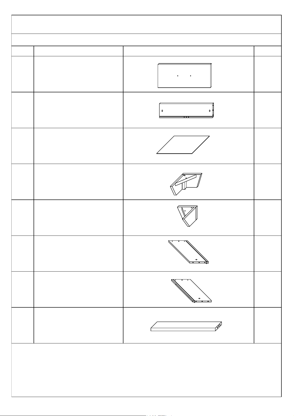
ITEM
N7
N8
N9
17
18
19
20
21
DESCRIPTION
DRAWER HEAD
DRAWER BACK PANEL
DRAWER BOTTOM PANEL
LEG (i)
LEG (ii)
DRAWER LEFT PANEL
DRAWER RIGHT PANEL
DRAWER BOTTOM SUPPORT RAIL
QTY
2 PCS
2 PCS
2 PCS
2 PCS
2 PCS
2 PCS
2 PCS
2 PCS
DRAWING
PARTS LIST
Page 5
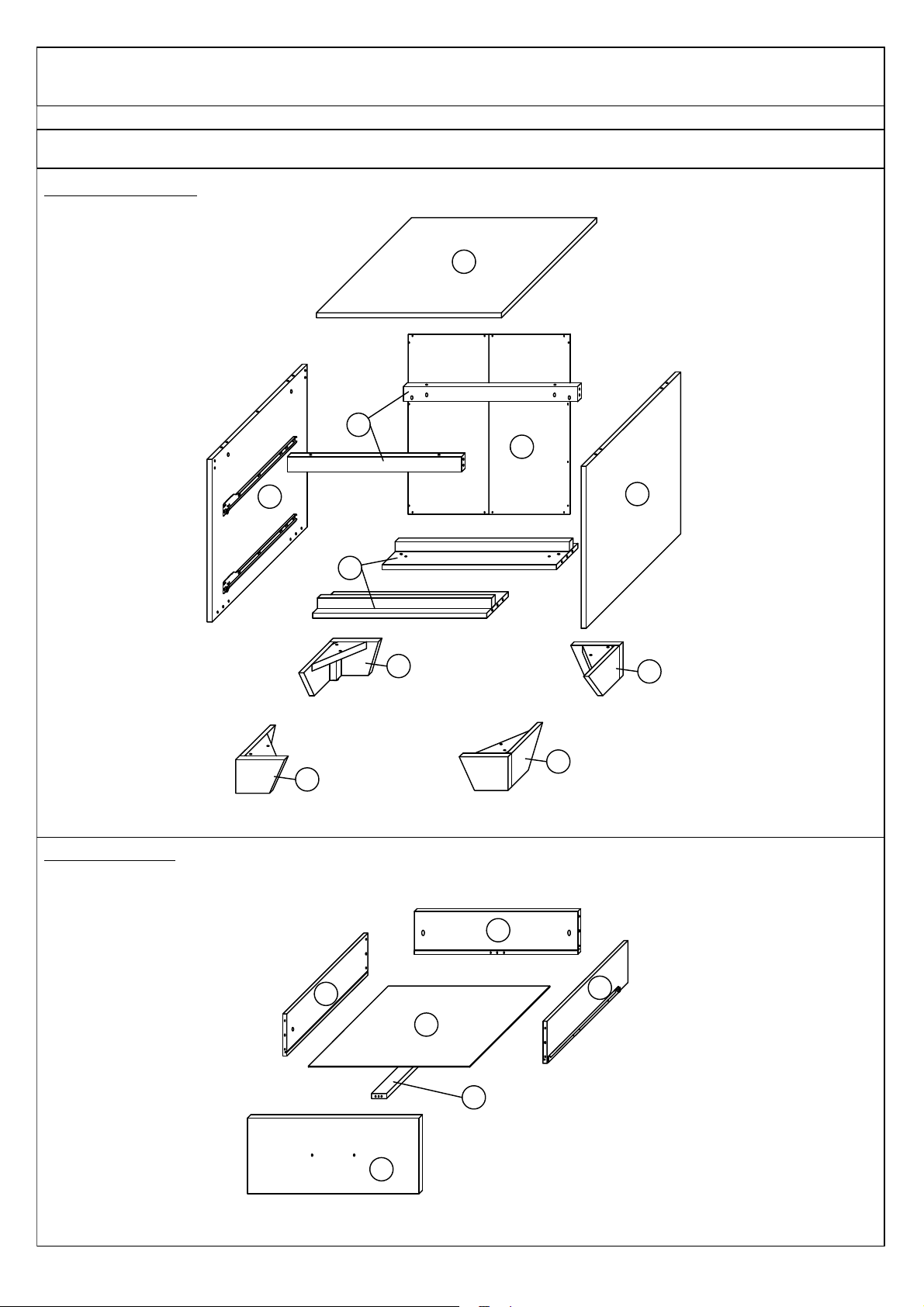
PARTS ' LOCATION
NIGHTSTAND x 1 PC
DRAWER x 2 PCS
N1
N2
N3
N4
N5
N6
17
17
18
18
N7
19
20
N8
N9
21
ASSEMBLY INSTRUCTION
Page 6
ASSEMBLY INSTRUCTION
ASSEMBLY STEPS
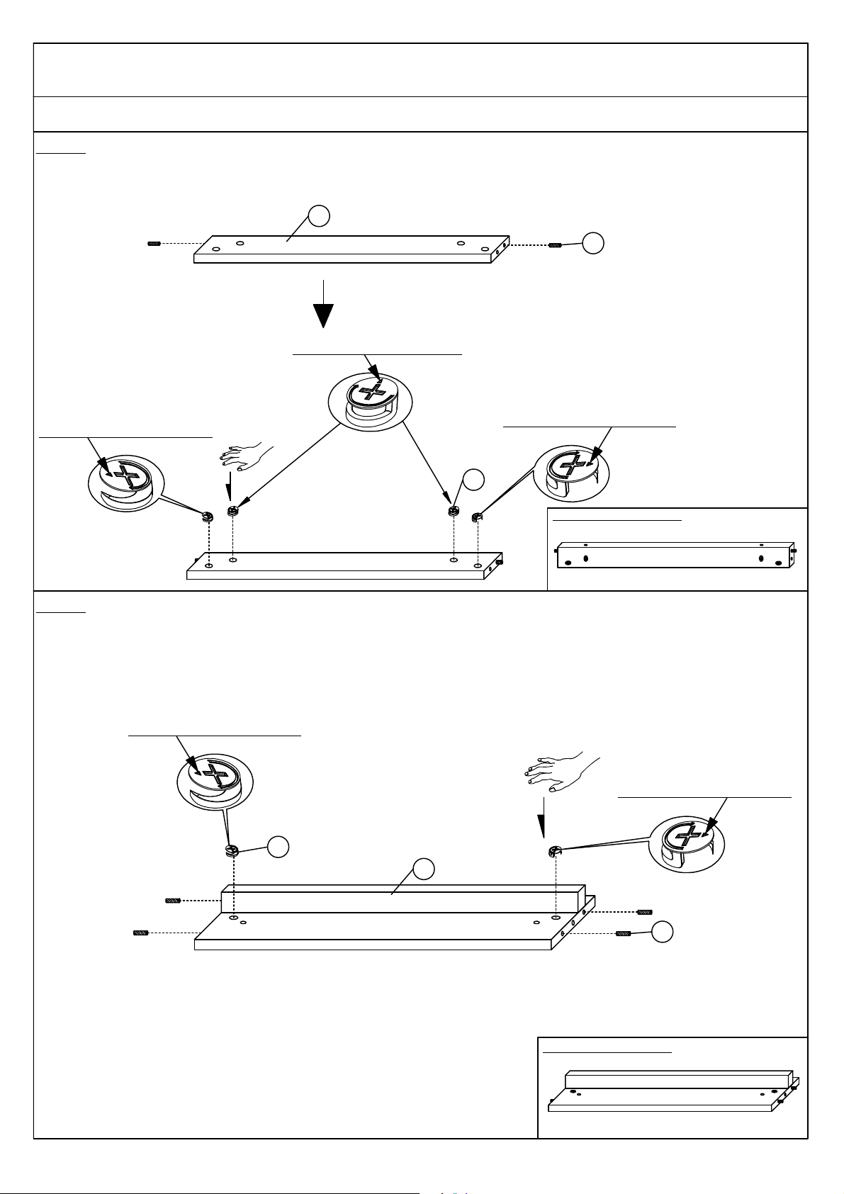
STEP 1
STEP 2
Assembled become like this
C
Arrow need to face upside.
Arrow need to face outside.
Arrow need to face outside.
Assembled become like this
Arrow need to face outside.
Arrow need to face outside.
C
A
A
N4
N5
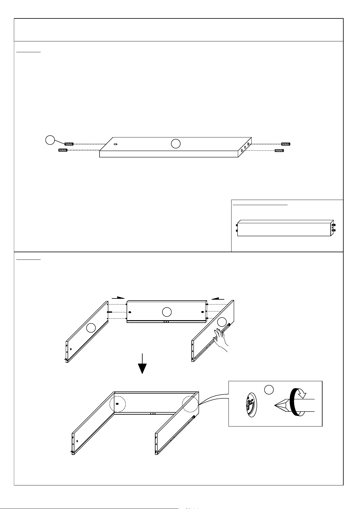
Insert 2 pieces WOOD DOWEL (C) to 1 piece LEFT AND RIGHT SUPPORT RAIL (N4) . Then insert 4 pieces MINIFIX
CAM LOCK (A) by your hand as shown.This step needs to be done twice.
Insert 4 pieces WOOD DOWEL (C) and 2 pieces MINIFIX CAM LOCK (A) to 1 piece BOTTOM PANEL (N5) as
shown.This step needs to be done twice.
Page 7
ASSEMBLY INSTRUCTION
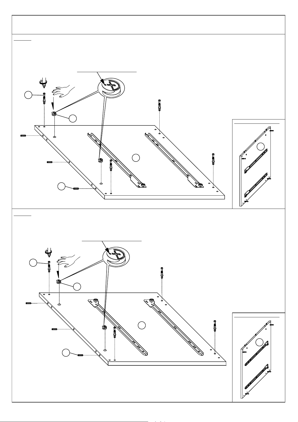
STEP 3
STEP 4
Assembled become like this
Assembled become like this
C
A
B
Arrow need to face upside.
Arrow need to face upside.
A
B
C
Insert 2 pieces MINIFIX CAM LOCK (A) , 4 pieces MINIFIX CAM BOLT (B) and 3 pieces WOOD DOWEL (C) to the
LEFT PANEL (N2) as shown.
Insert 2 pieces MINIFIX CAM LOCK (A) , 4 pieces MINIFIX CAM BOLT (B) and 3 pieces WOOD DOWEL (C) to the
RIGHT PANEL (N3) as shown.
N2
N3
N2
N3
Page 8
ASSEMBLY INSTRUCTION
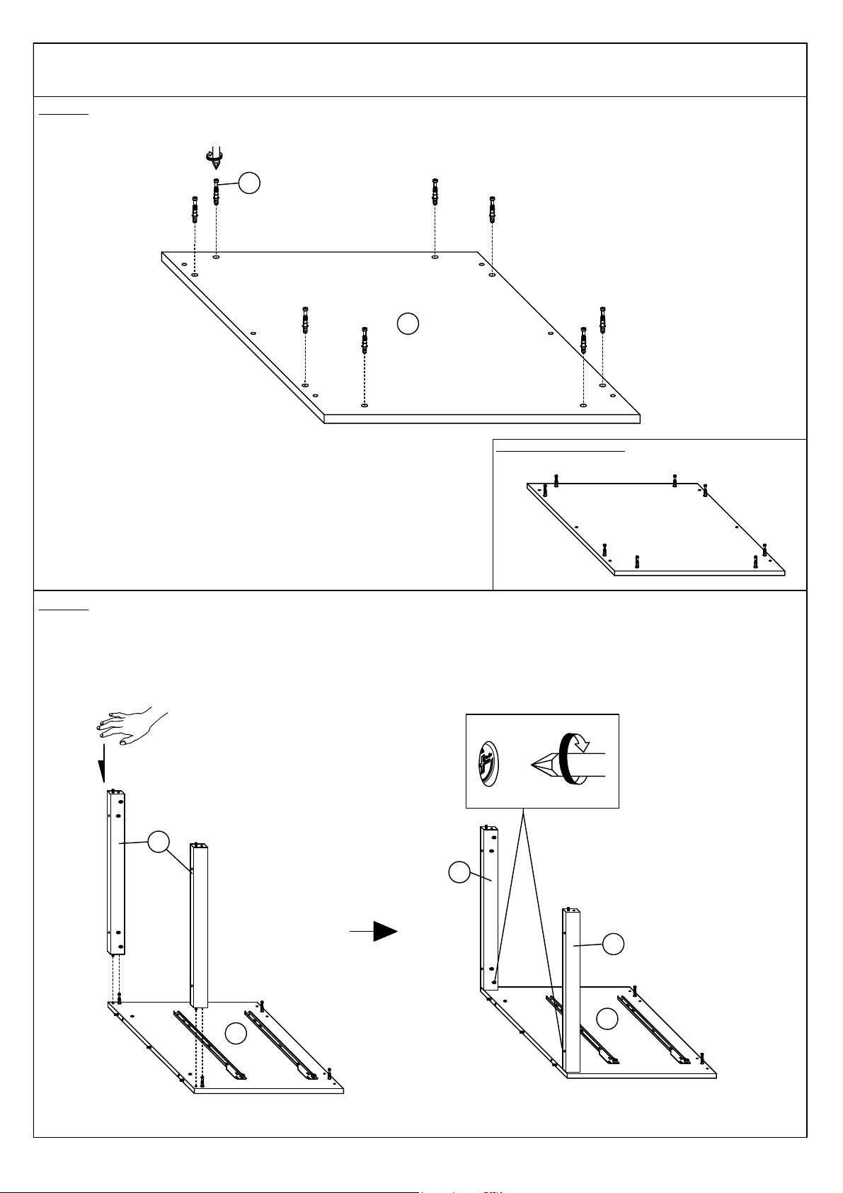
STEP 5
STEP 6
B
N1
Assembled become like this
N2
N4
Insert 8 pieces MINIFIX CAM BOLT (B) to the TOP PANEL (N1) as shown.
Align the position of hole then combine the LEFT AND RITGH SUPPORT RAILS (N4) to the LEFT PANEL (N2) by your
hand. Then, tighten the 2 pieces MINIFIX CAM LOCK (A) at (N4) marked by the arrows (pre-insert in step 1) as shown.
N2
N4
N4
Page 9
STEP 8
INSIDE VIEW
N3
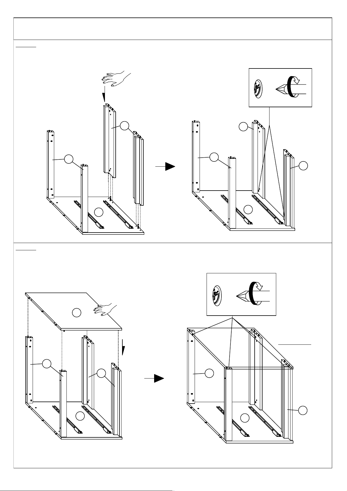
Align the position of hole then combine the RIGHT PANEL (N3) to the LEFT AND RIGHT SUPPORT RAILS (N4) and
the BOTTOM PANELS (N5) by your hand . After that , tighten the 4 pieces MINIFIX CAM LOCK (A) at (N4) and (N5)
marked by the arrows (pre-insert in step 1 and 2) as shown.
ASSEMBLY INSTRUCTION
Align the position of hole then combine the BOTTOM PANELS (N5) to the LEFT PANEL (N2) by your hand. Then ,
tighten the 2 pieces MINIFIX CAM LOCK (A) at (N5) marked by the arrows (pre-insert in step 2) as shown.
N5
STEP 7
N4
N2
N4
N2
N5
N2
N5
N4
N5
N4
N2
N5
Page 10
ASSEMBLY INSTRUCTION
STEP 9
STEP 10
C
18
18
17
17
E
F
G
N
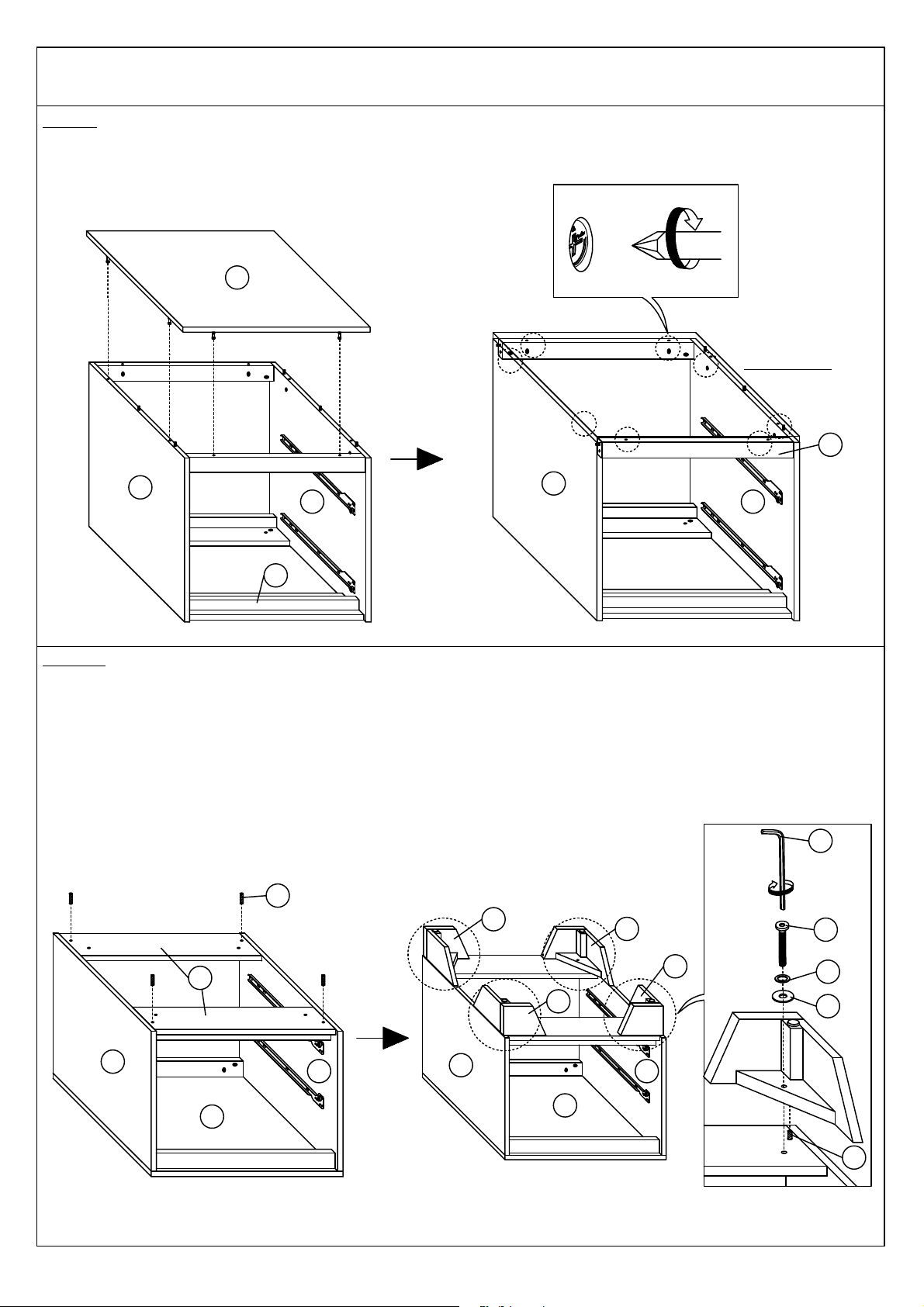
Align the position of hole then combine the TOP PANEL (N1) to the frame .Then , tighten the remaining 8 pieces
MINIFIX CAM LOCK (A) at (N2),(N3) and (N4) marked by the arrows (pre-insert in step 1, 3 and 4) as shown.
Insert 4 pieces WOOD DOWEL (C) to the BOTTOM PANELS (N5). Then, align the position of hole and insert the
LEGS(i) and (ii) - (17)&(18). After that , insert the 4 pieces JCBC SCREW (E) , SPRING WASHER (F) and FLAT
WASHER (G) as shown.
N1
N2
N3
N5
N5
N2
N3
N1
INSIDE VIEW
N3
N2
n4
N1
N2
N3
C
Page 11
ASSEMBLY INSTRUCTION
STEP 11
STEP 12
Assembled become like this
B
N7
Assembled become like this
Arrow need to face front.
19
A
B
D
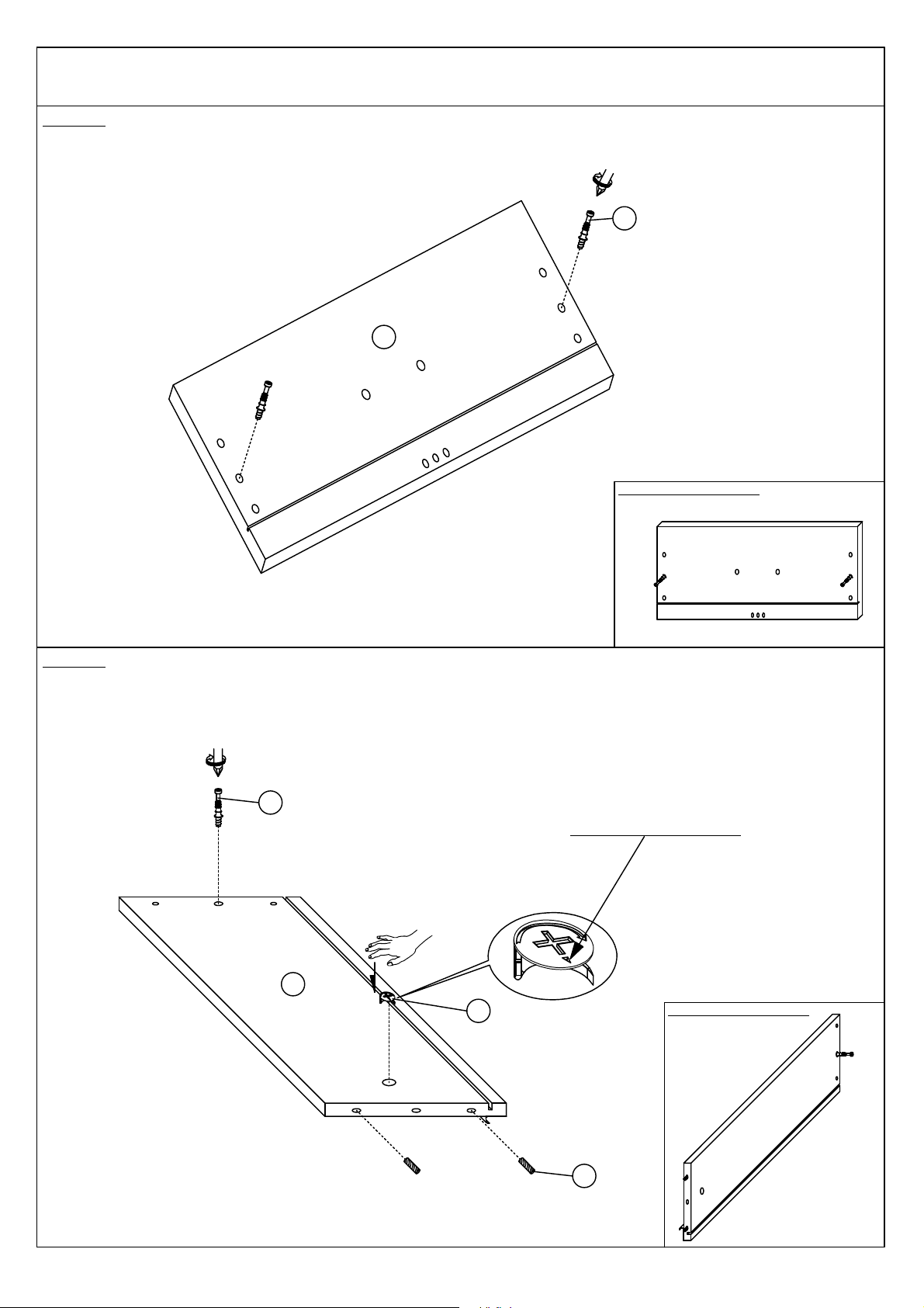
Insert 2 pieces MINIFIX CAM BOLT (B) to 1 piece DRAWER HEAD (N7) as shown.This step needs to be done twice.
Insert 1 piece MINIFIX CAM LOCK (A) , 1 piece MINIFIX CAM BOLT (B) and 2 pieces WOOD DOWEL (D) to 1 piece
DRAWER LEFT PANEL (19) as shown.This step needs to be done twice.
Page 12
ASSEMBLY INSTRUCTION
STEP 13
STEP 14
Assembled become like this
Assembled become like this
A
Arrow need to face front.
B
D
D
A
20
N8
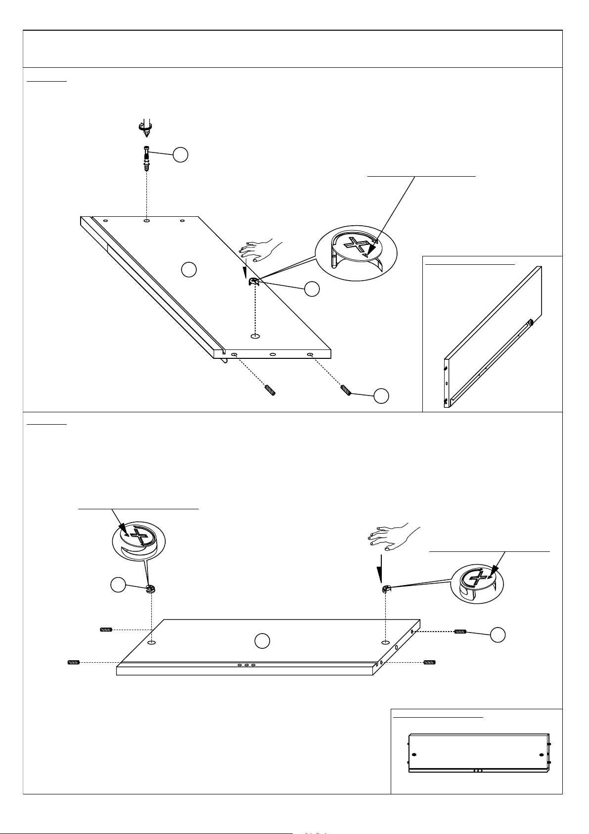
Insert 1 piece MINIFIX CAM LOCK (A) , 1 piece MINIFIX CAM BOLT (B) and 2 pieces WOOD DOWEL (D) to 1 piece
DRAWER RIGHT PANEL (20) as shown.This step needs to be done twice.
Insert 2 pieces MINIFIX CAM LOCK (A) and 4 pieces WOOD DOWEL (D) to 1 piece DRAWER BACK PANEL (N8) as
shown.This step needs to be done twice.
Arrow need to face outside.
Arrow need to face outside.
Page 13
ASSEMBLY INSTRUCTION
STEP 15
STEP 16
Assembled become like this
N8
19
20
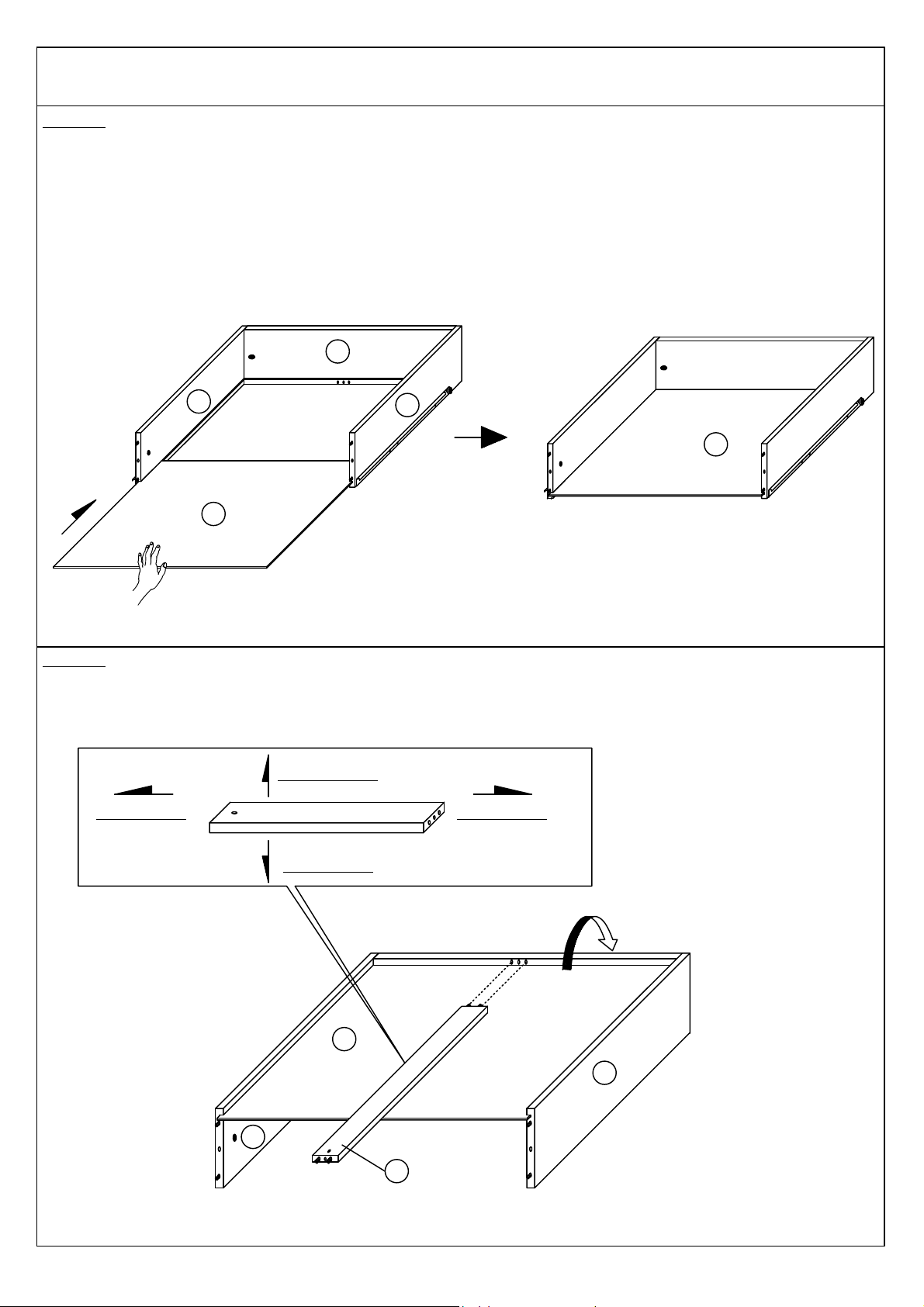
Insert 4 pieces WOOD DOWEL (D) to 1 piece DRAWER BOTTOM SUPPROT RAIL (21) as shown. This step needs to
be done twice.
Align the position of hole then combine 1 piece DRAWER LEFT and DRAWER RIGHT PANEL (19)&(20) to 1 piece
DRAWER BACK PANEL (N8) by your hand. Then , tighten the 2 pieces MINIFIX CAM LOCK (A) at (N8) (pre-insert in
step 14) as shown. This step needs to be done twice.
N8
D
21
Page 14
ASSEMBLY INSTRUCTION
STEP 17
STEP 18
N9
21
Put 1 piece DRAWER BOTTOM PANEL (N9) into the gap by your hand.Then , reverse the drawer frame as shown.This
step needs to be done twice.
Align the position of hole then insert 1 piece DRAWER BOTTOM SUPPORT RAIL (21) to drawer frame as shown.This
step needs to be done twice.
90 °
N8
19
20
N9
N9
19
20
Face to (N7) Face to (N8)
Face to down
Face to (N9)
Page 15
ASSEMBLY INSTRUCTION
INSIDE VIEW
90 °
&
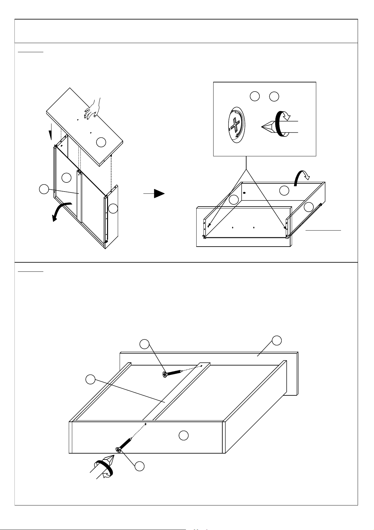
Align the position of hole then combine 1 piece DRAWER HEAD (N7) to drawer frame by your hand.Then reverse it
again and tighten the 2 pieces MINIFIX CAM LOCK at (19)&(20) (pre-insert in step 12 and 13) as shown. This step
needs to be done twice.
STEP 19
N7
20
N9
21
20
19
N8
19
20
Insert 1 piece CSK C/B SCREW (O) to DRAWER BOTTOM SUPPORT RAIL (21) and DRAWER BACK PANEL (N8) as
shown. This step needs to be done twice.
STEP 20
21
O
O
N8
N7
180 °
Page 16
ASSEMBLY INSTRUCTION
M
I
STEP 21
STEP 22
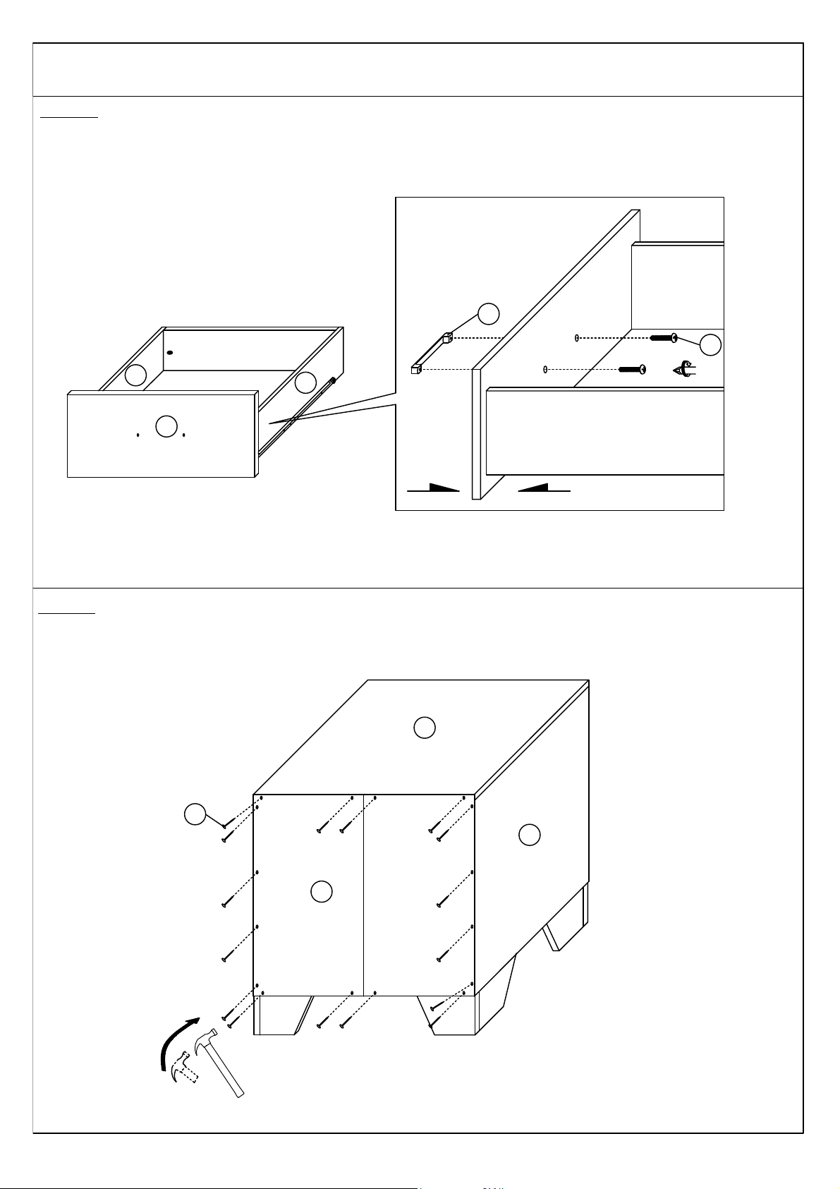
Fix 1 piece HANDLE (M) with 2 pieces TRUSS M-SCREW (I) as shown.This step needs to be done twice.
Align the position of hole then insert the 16 pieces 6/8" NAIL (L) at the BACK PANEL (N6) with using a hammer as shown.
N6
L
N2
N1
N7
19
20
Page 17
ASSEMBLY INSTRUCTION
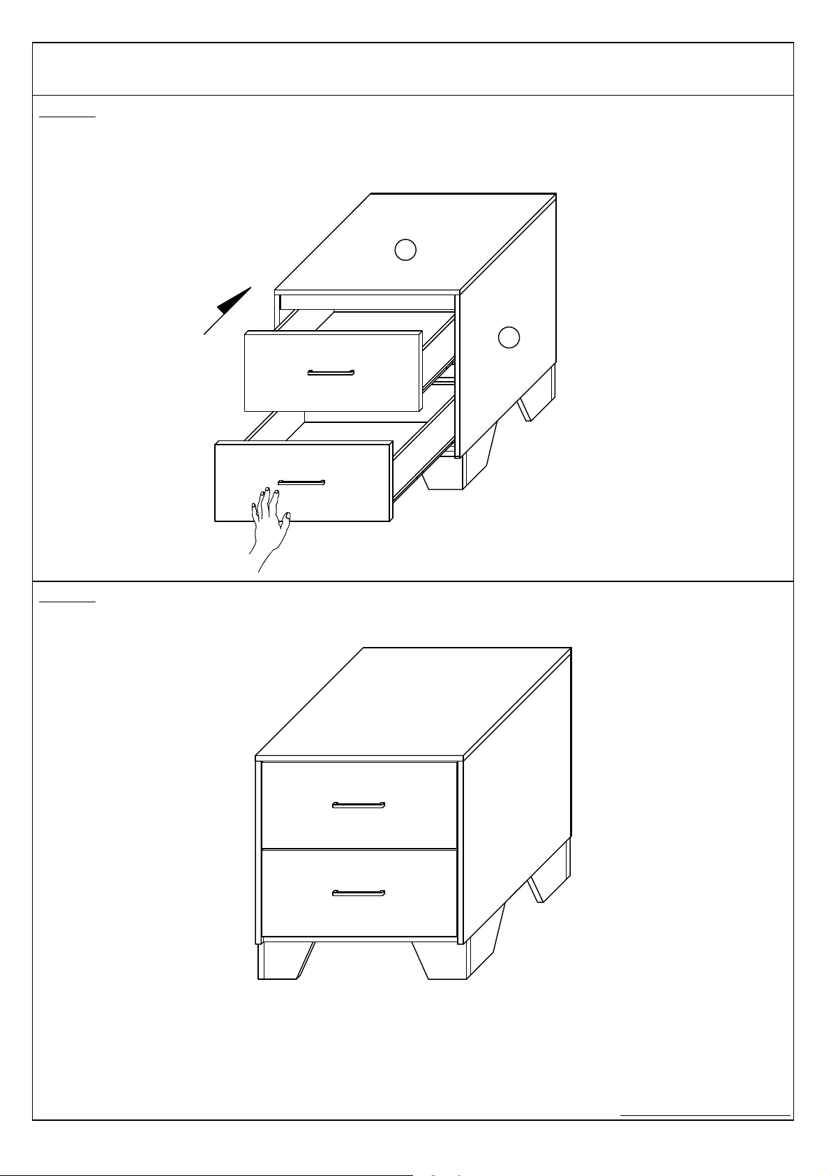
ASSEMBLY COMPLETED
Align the position of drawer and push inside exactly by your hand as shown.
STEP 23
N3
N1
STEP 24
 Loading...