

Page 1

ZAURMAG1A1A
ZAURSTG1A1A
ZAURCTG1A00
ZAURA™ RF Wireless
Lighting Control
Installation Guide
UM022903-0311
Copyright ©2011 Zilog
www.zilog.com
®
. All rights reserved.
Page 2

ZAURA™ RF Wireless Lighting Control
Warning:
Installation Guide
DO NOT USE THIS PRODUCT IN LIFE SUPPORT SYSTEMS.
LIFE SUPPORT POLICY
ZILOG’S PRODUCTS ARE NOT AUTHORIZED FOR USE AS CRITICAL COMPONENTS IN LIFE
SUPPORT DEVICES OR SYSTEMS WITHOUT THE EXPRESS PRIOR WRITTEN APPROVAL OF
THE PRESIDENT AND GENERAL COUNSEL OF ZILOG CORPORATION.
As used herein
Life support devices or systems are devices which (a) are intended for surgical implant into the body, or (b)
support or sustain life and whose failure to perform when properly used in accordance with instructions for
use provided in the labeling can be reasonably expected to result in a significant injury to the user. A
critical component is any component in a life support device or system whose failure to perform can be
reasonably expected to cause the failure of the life support device or system or to affect its safety or
effectiveness.
ii
Document Disclaimer
©2011 Zilog, Inc. All rights reserved. Information in this publication concerning the devices, applications,
or technology described is intended to suggest possible uses and superseded. ZILOG, INC. DOES NOT
ASSUME LIABILITY FOR OR PROVIDE A REPRESENTATION OF ACCURACY OF THE
INFORMATION, DEVICES, OR TECHNOLOGY DESCRIBED IN THIS DOCUMENT. ZILOG ALSO
DOES NOT ASSUME LIABILITY FOR INTELLECTUAL PROPERTY INFRINGEMENT RELATED
IN ANY MANNER TO USE OF INFORMATION, DEVICES, OR TECHNOLOGY DESCRIBED
HEREIN OR OTHERWISE. The information contained within this document has been verified according
to the general principles of electrical and mechanical engineering.
ZAURA is a trademark of Zilog, Inc. All other product or service names are the property of their respective
owners.
UM022903-0311 LIFE SUPPORT POLICY
Page 3

ZAURA™ RF Wireless Lighting Control
Installation Guide
Revision History
Each instance of revision history reflects a change to this document from its previously
published version. For more details, refer to the corresponding pages or appropriate links
listed in Table 1.
Table 1. History of this Document
Date Revision Level Description Page No.
Mar 2011 03 Expanded for clarity, comprehensiveness, FAQs All
Dec 2010 02 Updated Configuration Tool sections; replaced images All
Oct 2010 01 Original issue N/A
iii
UM022903-0311 Revision History
Page 4

Safeguards
Caution:
The following precautions must be observed when working with the devices described in
this document:
When replacing a ZAURA™ Starter, it is necessary to turn of f the main power to the luminaries.
• Be sure to match starter wattage with lamp wattage.
• Install and use the devices described herein in accordance with applicable electrical
codes and regulations.
• Risk of damage can occur if the battery is replaced by an incorrect battery type.
• Removal of the lens can cause irreversible damage to the sensor and void the warranty
of the ZAURA Detector.
ZAURA™ RF Wireless Lighting Control
Installation Guide
iv
UM022903-0311 Safeguards
Page 5

Table of Contents
Revision History . . . . . . . . . . . . . . . . . . . . . . . . . . . . . . . . . . . . . . . . . . . . . . . . . . . . . . . . . . . . .iii
Safeguards. . . . . . . . . . . . . . . . . . . . . . . . . . . . . . . . . . . . . . . . . . . . . . . . . . . . . . . . . . . . . . . . . .iv
General Description . . . . . . . . . . . . . . . . . . . . . . . . . . . . . . . . . . . . . . . . . . . . . . . . . . . . . . . . . . 1
System Overview . . . . . . . . . . . . . . . . . . . . . . . . . . . . . . . . . . . . . . . . . . . . . . . . . . . . . . . . . . 1
Applications . . . . . . . . . . . . . . . . . . . . . . . . . . . . . . . . . . . . . . . . . . . . . . . . . . . . . . . . . . . . . . 1
Physical Dimensions . . . . . . . . . . . . . . . . . . . . . . . . . . . . . . . . . . . . . . . . . . . . . . . . . . . . . . . 3
ZAURA Master Unit . . . . . . . . . . . . . . . . . . . . . . . . . . . . . . . . . . . . . . . . . . . . . . . . . . . . 4
ZAURA Starter Unit . . . . . . . . . . . . . . . . . . . . . . . . . . . . . . . . . . . . . . . . . . . . . . . . . . . . 4
ZAURA Configuration Tool . . . . . . . . . . . . . . . . . . . . . . . . . . . . . . . . . . . . . . . . . . . . . . 5
ZAURA™ RF Wireless Lighting Control
Installation Guide
v
ZAURA System Operation. . . . . . . . . . . . . . . . . . . . . . . . . . . . . . . . . . . . . . . . . . . . . . . . . . . . . 6
ZAURA Master/Range Extender Operation . . . . . . . . . . . . . . . . . . . . . . . . . . . . . . . . . . . . . 6
Motion Sensor for Occupancy Detection . . . . . . . . . . . . . . . . . . . . . . . . . . . . . . . . . . . . 6
Light Sensor for Daylight Harvesting . . . . . . . . . . . . . . . . . . . . . . . . . . . . . . . . . . . . . . . 6
ZAURA Starter Operation . . . . . . . . . . . . . . . . . . . . . . . . . . . . . . . . . . . . . . . . . . . . . . . . . . . 7
Configuration Tool Operation . . . . . . . . . . . . . . . . . . . . . . . . . . . . . . . . . . . . . . . . . . . . . . . . 8
ZAURA System Installation and Configuration. . . . . . . . . . . . . . . . . . . . . . . . . . . . . . . . . . . . . 9
Installation Summary . . . . . . . . . . . . . . . . . . . . . . . . . . . . . . . . . . . . . . . . . . . . . . . . . . . . . . . 9
Assessing Room Requirements . . . . . . . . . . . . . . . . . . . . . . . . . . . . . . . . . . . . . . . . . . . . . . 11
Determine Master and Range Extender Locations . . . . . . . . . . . . . . . . . . . . . . . . . . . . 11
Determine Luminary Configuration . . . . . . . . . . . . . . . . . . . . . . . . . . . . . . . . . . . . . . . 13
Inventory Parts and Tools . . . . . . . . . . . . . . . . . . . . . . . . . . . . . . . . . . . . . . . . . . . . . . . 15
Mount Base Plates . . . . . . . . . . . . . . . . . . . . . . . . . . . . . . . . . . . . . . . . . . . . . . . . . . . . . 15
Configuring ZAURA Masters . . . . . . . . . . . . . . . . . . . . . . . . . . . . . . . . . . . . . . . . . . . . . . . 18
Install Batteries . . . . . . . . . . . . . . . . . . . . . . . . . . . . . . . . . . . . . . . . . . . . . . . . . . . . . . . 24
Set Up and Install ZAURA Virtual Dimming Luminaries . . . . . . . . . . . . . . . . . . . . . . 26
Set Up and Install ZAURA Standard Luminaries . . . . . . . . . . . . . . . . . . . . . . . . . . . . . 29
Mount Master/Range Extenders . . . . . . . . . . . . . . . . . . . . . . . . . . . . . . . . . . . . . . . . . . 31
Configuring ZAURA Range Extenders . . . . . . . . . . . . . . . . . . . . . . . . . . . . . . . . . . . . . . . . 33
Reconfiguration of Masters and Starters. . . . . . . . . . . . . . . . . . . . . . . . . . . . . . . . . . . . . . . . . . 34
Changing the Master Type . . . . . . . . . . . . . . . . . . . . . . . . . . . . . . . . . . . . . . . . . . . . . . . . . . 34
Changing a Master to Range Extender Mode . . . . . . . . . . . . . . . . . . . . . . . . . . . . . . . . 34
Changing a Range Extender to Master Mode . . . . . . . . . . . . . . . . . . . . . . . . . . . . . . . . 34
Moving a Master to a New Location . . . . . . . . . . . . . . . . . . . . . . . . . . . . . . . . . . . . . . . 35
Deassociating a Starter . . . . . . . . . . . . . . . . . . . . . . . . . . . . . . . . . . . . . . . . . . . . . . . . . . . . . 3 5
Luminary Method . . . . . . . . . . . . . . . . . . . . . . . . . . . . . . . . . . . . . . . . . . . . . . . . . . . . . 35
Configuration Tool Method . . . . . . . . . . . . . . . . . . . . . . . . . . . . . . . . . . . . . . . . . . . . . 36
UM022903-0311 Table of Contents
Page 6

ZAURA™ RF Wireless Lighting Control
Installation Guide
Deassociating a Range Extender . . . . . . . . . . . . . . . . . . . . . . . . . . . . . . . . . . . . . . . . . . . . . 36
Master Method . . . . . . . . . . . . . . . . . . . . . . . . . . . . . . . . . . . . . . . . . . . . . . . . . . . . . . . 36
Range Extender Method . . . . . . . . . . . . . . . . . . . . . . . . . . . . . . . . . . . . . . . . . . . . . . . . 37
Frequently Asked Questions. . . . . . . . . . . . . . . . . . . . . . . . . . . . . . . . . . . . . . . . . . . . . . . . . . . 38
Technical Specifications . . . . . . . . . . . . . . . . . . . . . . . . . . . . . . . . . . . . . . . . . . . . . . . . . . . . . . 40
Ordering Information . . . . . . . . . . . . . . . . . . . . . . . . . . . . . . . . . . . . . . . . . . . . . . . . . . . . . . . . 43
Room Configuration Examples. . . . . . . . . . . . . . . . . . . . . . . . . . . . . . . . . . . . . . . . . . . . . . . . . 44
Customer Support . . . . . . . . . . . . . . . . . . . . . . . . . . . . . . . . . . . . . . . . . . . . . . . . . . . . . . . . . . . 53
vi
UM022903-0311 Table of Contents
Page 7

General Description
Note:
Zilog’s ZAURA RF Wireless Communications Technology for Fluorescent Lighting is an
occupancy detector energy management system designed to save energy in starter-based
lighting. Upon easy plug-and-play installation, the system will detect occupancy in a room
and switch the starter-based lighting on and off without the use of control wiring.
The ZAURA RF Wireless Lighting Control System can detect occupancy in rooms of
approximately 100 square meters in size. Larger rooms can be controlled through the use
of additional occupancy detectors.
System Overview
ZAURA™ RF Wireless Lighting Control
Installation Guide
1
The ZAURA system provides power savings in conventional fluorescent lamp installations by turning off lamps when the room is unoccupied or when sufficient natural light is
available. ZAURA consists of three unit types: Masters, Starters and an optional ZAURA
Configuration Tool.
Masters are battery-powered, perform occupancy and natural light detection, and command ZAURA starters via wireless communication. A Master can be configured as a Standard Master which controls the ZAURA starters, or as a Range Extender which provides
additional occupancy detection information to a Standard Master so that the occupancy
detection range of the Standard Master is extended.
Starters control fluorescent lamps in standard ballast systems (L, C) based on wireless
commands from the Master. A ZAURA Starter can be configured as one of two types: as a
ZAURA Starter or as a ZAURA Virtual Dimming Starter. The latter is intended to be
installed near windows and is commanded to extinguish lamps if sufficient natural light
exists. ZAURA Starters are typically associated wirelessly to their Master.
Non-ZAURA (original) starters can also be used, for example, to allow selected lamps to
remain on 100% of the time for safety reasons.
The ZAURA Configuration Tool is typically used to change existing ZAURA Starter
associations, though it can also be used to place the ZAURA Starter into
for an initial association, e.g., if difficulties are encountered with wireless association.
Associate mode
Applications
The ZAURA RF Wireless Lighting Control System is designed for use in schools, offices,
industrial buildings and similar applications. It is optimized for ceiling heights from 2.5 to
UM022903-0311 General Description
Page 8

ZAURA™ RF Wireless Lighting Control
Installation Guide
3.5 meters. The product is designed for installation within minutes without drilling or wiring. One ZAURA Master can control up to 128 lights with superior low power, long range
and radio frequency communication.
Figure 1 shows an out-of-the-box version of the ZAURA Detector including the Master/
Range Extender, the Starter and the ZAURA Configuration Tool; Figure 2 offers a
glimpse into the components of the ZAURA Detector.
2
Figure 1. The ZAURA Master Unit/Range Extender and the ZAURA Starter
UM022903-0311 General Description
Page 9

ZAURA™ RF Wireless Lighting Control
Installation Guide
3
Figure 2. A Components Breakout of the ZAURA System
Physical Dimensions
The dimensions of the three ZAURA system components are discussed in this section.
UM022903-0311 General Description
Page 10
ZAURA™ RF Wireless Lighting Control
ZAURA Master Unit
The images in Figure 3 show the height and width of the ZAURA Master Unit.
Installation Guide
4
Figure 3. ZAURA Master Unit Dimensions
ZAURA Starter Unit
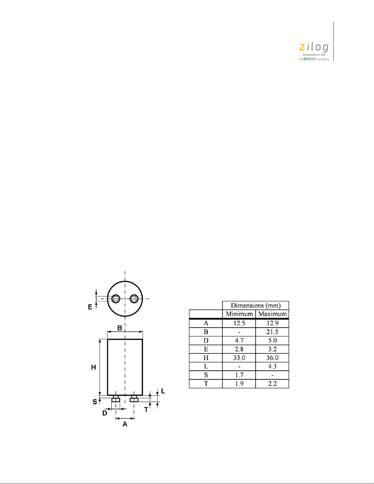
Figure 4 shows the dimensions of the ZAURA Starter Unit.
Figure 4. Starter Component Dimensions
UM022903-0311 General Description
Page 11

ZAURA™ RF Wireless Lighting Control
ZAURA Configuration Tool
Figure 5 shows the dimensions of the ZAURA Configuration Tool.
Installation Guide
5
Figure 5. ZAURA Configuration Tool Dimensions
UM022903-0311 General Description
Page 12

ZAURA™ RF Wireless Lighting Control
ZAURA System Operation
System communication is performed wirelessly. In order for a Master and its Starters and
Range Extenders to communicate with each other, they must be associated (bound) to
each other. (To learn more about master/starter association, refer to the Associating a
ZAURA Starter with a Master section on page 30.) If any device in the system loses
power, then after power is restored, there can be a delay of up to several minutes before its
communication is restored.
This chapter also describes the operation of the ZAURA Configuration Tool.
ZAURA Master/Range Extender Operation
Installation Guide
6
This section describes the operation of the Motion and Light Sensor features of the
ZAURA Master/Range Extender.
Motion Sensor for Occupancy Detection
The Master/Range Extender utilizes Zilog’s high-performance Z8 Encore! XP® Microcontroller combined with a lens and Passive Infrared (PIR) sensor that have been optimized to detect occupancy. If occupancy has not been detected based on a userconfigurable time delay setting, the lights in the room are turned off to conserve power.
Light Sensor for Daylight Harvesting
For many installations, natural light is available during daytime and adequate lighting can
be provided even when certain lamps are turned off. The daylight harvesting feature of
this system saves power by automatically turning off luminaries connected to V irtual Dim-
ming Starters when a predetermined brightness level (virtual dimming threshold) of natural light is exceeded. Luminaries connected to ZAURA starters remain on.
ZAURA Virtual Dimming Starters should be installed to control luminaries in areas that
receive relatively strong natural light. A certain amount of hysteresis can exist such that
the starting of dimming and stopping of dimming occur at different natural light levels in
order to avoid on/off oscillation.
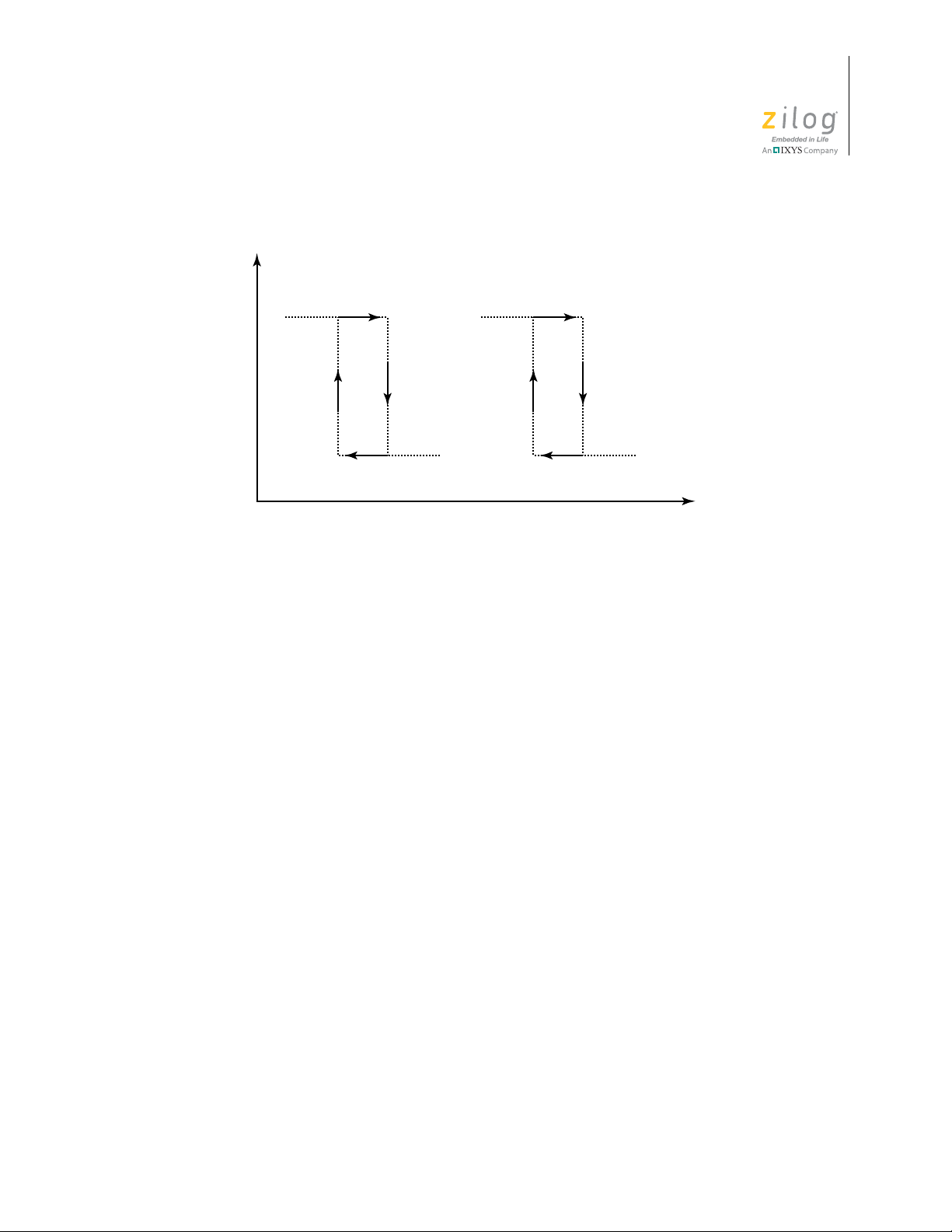
Natural light levels are also evaluated before lamp ignition. For example, when all luminaries are initially off and motion is detected, the Virtual Dimming luminaries are not
ignited if the natural light in the room exceeds the dimming threshold. All luminaries can
be turned off if the measured light level is 3 times greater than the virtual dimming threshold, as shown in Figure 6. This feature can optionally be disabled using a DIP Switch
inside the Master Unit.
UM022903-0311 ZAURA System Operation
Page 13
ZAURA™ RF Wireless Lighting Control
Dimming Starter Non-Dimming Starter
Dimming Threshold
3X Dimming Threshold
Natural Light Level
Lamp Status
On
Off
Installation Guide
7
Figure 6. Daylight Harvesting
ZAURA Starter Operation
When the Master is operating, ZAURA Starters respond to commands from the Master. If
the room’s light switch is set to the OFF position, all lamps will be turned OFF irrespective of Master commands. When the light switch is set to the ON position, all lamps will
initially be turned ON. After communication is reestablished between the Master and its
associated ZAURA Starters, Master control of the ZAURA Starters resumes.
In the absence of a Master, or when the Master contains either no battery or a low battery,
the ZAURA starters perform traditional ON/OFF behavior based on the position of the
light switch.
When commanded by its Master to ignite or extinguish a lamp, the ZAURA Starter will
perform a limited number of attempts. This behavior prevents excessive ignite and extinguish strikes on lamps near the end of their life cycles. The ZAURA Starter will again
attempt to ignite and extinguish a lamp if the lamps are cycled by either the Master using
ON/OFF commands or by manual power cycling the lamps OFF for one minute, then ON
using the light switch.
UM022903-0311 ZAURA System Operation
Page 14

For safety reasons, non-ZAURA (original) starters can be used to allow selected lamps to
Note:
remain ON whenever the switch is ON.
Configuration Tool Operation
The ZAURA Configuration Tool, though its use can be relatively infrequent, can be
employed for the following reasons:
•
A Starter is required to be associated to a different Master
•
A Starter is required to be changed from non-dimming to dimming, or vice versa
•
A Starter is required to be associated outside of a luminary
ZAURA™ RF Wireless Lighting Control
Installation Guide
8
Typically, one or two configuration tools are sufficient for a facility. The ZAURA Configuration Tool can be used with any ZAURA Starter, but is not required to be associated
with a Master. Refer to the Configuration Tool Method
details.
section on page 36 for more
UM022903-0311 ZAURA System Operation
Page 15

ZAURA™ RF Wireless Lighting Control
ZAURA System Installation and Configuration
This chapter describes room requirements assessment, battery installation, starter installation and association, and how to configure and mount your ZAURA masters and range
extenders. The chapter begins with an Installation Summary section, which provides a
blueprint suitable for installers who have previously performed a ZAURA installation.
Installation Summary
The steps in this section summarize the sequence of a typical ZAURA System installation.
Links to additional sections of this document have been added to provide more detailed
assistance.
Installation Guide
9
1. Determine the location of Standard Masters (and Range Extenders, if required). For
additional assistance with this step, see the the Determine Master and Range Extender
Locations section on page 11.
2. Determine luminary configuration. For additional assistance with this step, see the the
Determine Luminary Configuration
configuring your luminaries are:
– Which luminaries, if any, will be using their original starters (consider safety con-
cerns)
– Which luminaries will contain ZAURA Starters
– Which luminaries will contain ZAURA Virtual Dimming Starters (typically for
placement near windows)
3. Inventory your parts (Masters/Range Extenders, Starters, etc.) and tools to ensure that
you have sufficient quantities for the required installation. For additional assistance
with this step, see the the Inventory Parts and Tools
4. Mount base plate(s) to the ceiling in the location(s) you determined in Step 1 using the
screws or the double-sided tape provided.
see the the Mount Base Plates
5. Configure the ZAURA Masters. For additional assistance with this step, see the the
Configuring ZAURA Masters
section on page 13. Items to consider when
section on page 15.
1
. For additional assistance with this step,
section on page 15.
section on page 18.
1. Zilog recommends using the screws provided with the ZAURA System when mounting the Master base plate;
however, double-sided tape is provided with the installation hardware. Simply press the double-sided tape to the
base plate, then mount the base plate securely to the mounting surface to ensure good adherence. Depending on the
mounting surface, however, caution should be used when removing the base plate when it has been affixed with the
double-sided tape, because damage to the Master housing and/or to the mounting surface could occur.
UM022903-0311 ZAURA System Installation and Configuration
Page 16

ZAURA™ RF Wireless Lighting Control
Installation Guide
a. Set the Master type switch to the Standard (OFF, OFF) position.
b. Make sure the mode is set to Normal Operation (i.e., DIP switches 1, 2 and 3 are
in the OFF position).
c. Set the turn-off delay to the required value (the recommended setting is 5 min-
utes).
d. Adjust light and movement sensitivity, if required. For additional assistance with
this step, see the the Occupancy Detection Adjustment
Light Detection Adjustment
section on page 23.
section on page 22 and the
e. Install one battery. For additional assistance with this step, see the Install Batteries
section on page 24.
6. Configure the Range Extenders (if required). For additional assistance with this step,
see the Configuring ZAURA Range Extenders
section on page 33.
a. Set the Master type switch to Range Extender (OFF, ON) position.
b. Set DIP switches 1 through 8 to match the Master.
c. Adjust the Occupancy sensitivity POT, if required.
d. Install the batteries.
e. Associa te the Range Extender(s) to the appropriate Master.
10
7. Set the Virtual Dimming Luminaries (if no Virtual Dimming luminaries are required,
skip to Step 8). For additional assistance with this step, see the Set Up and Install
ZAURA Virtual Dimming Luminaries section on page 26.
a. Replace the original starters with ZAURA Starters.
b. Associate the ZAURA Virtual Dimming Starters to the Master.
c. Verify the association of all ZAURA Virtual Dimming Starters.
8. Set the Standard Luminaries to be controlled by the Master. For additional assistance
with this step, see the Set Up and Install ZAURA Standard Luminaries
section on
page 29.
a. Replace the original starters with ZAURA Starters in the remaining luminaries to
be controlled by the Master.
b. Associate ZAURA Starters to the Master. For additional assistance with this step,
see the Associating a ZAURA Starter with a Master
section on page 30.
c. Verify association of all ZAURA Starters.
9. Mount the Master to the previously installed base plate closest to the center of the
room. Mount the Range Extenders (if any) to their designated base plates. For
additional assistance with this step, see the Mount Master/Range Extenders
section on
page 31.
10. The room is complete.
UM022903-0311 ZAURA System Installation and Configuration
Page 17

ZAURA Starters and Virtual Dimming Starters are physically identical; however, they
Notes:
behave differently depending upon how they are associated. Zilog highly recommends
installing the ZAURA RF Wireless Lighting Control System one room at a time to avoid
possible communication issues during the association process.
Assessing Room Requirements
Before installing and configuring your ZAURA System, you’ll first want to establish
where you will install your ZAURA detectors based on the lighting needs of the room.
Determine Master and Range Extender Locations
ZAURA™ RF Wireless Lighting Control
Installation Guide
11
Typically, the ZAURA Master is located in the center of a room; however, differing levels
of expected activity in a room should be considered when determining the Master’s eventual mounting placement.
For example, a university lecture hall full of students will pose different lighting requirements than that same lecture hall when only the professor is occupying the room, grading
papers; i.e., the general seating area will not require lighting but the area surrounding the
professor’s lectern must continue to remain illuminated. By placing the Master closer to
the professor’s lectern, you can ensure maximum sensitivity to the professor’s movement
and reduce the chance that the lights turn off while the professor is alone in the room.
Figures 7 and 8 can help to determine whether installation is sufficiently covered by the
occupancy detection range of a single Master unit. If the situation requires, add Range
Extenders to achieve coverage. When placing multiple Range Extenders, locate the Master
toward the center of the grouping.
UM022903-0311 ZAURA System Installation and Configuration
Page 18

ZAURA™ RF Wireless Lighting Control
Installation Guide
12
Figure 7. Master Detection Radius vs. Ceiling Height
Figure 8. Detector Coverage Area
UM022903-0311 ZAURA System Installation and Configuration
Page 19

ZAURA™ RF Wireless Lighting Control
Installation Guide
Items to consider when locating Masters/Range Extenders:
•
There can only be one Master per control group
•
Coverage area, as shown in Figures 7 and 8
•
Clear line of sight from Master/Range Extender location to all main room entrances,
exits and areas where occupancy detection is required
•
Room obstructions such as pillars, walls, lockers, piping, etc.
•
Proper clearance around the mounting location
•
The ZAURA Master should be the only unit to determine light levels in the room and
to turn off the Virtual Dimming Luminaries
•
To better detect room light levels, the Master can be located closer to a natural light
source
13
•
A Range Extender does not evaluate the natural light levels in an area
•
Mounting material (wood vs. concrete vs. brick vs. porous ceiling panels)
•
Relatively dry area
•
Is there a requirement to have motion detection in every part of the room?
Determine Luminary Configuration
The ZAURA system for fluorescent lighting is very flexible to meet the lighting and
energy savings requirements for different situations. Figure 9 (also see Appendix A
page 44) illustrates how rooms can be configured. In the figure, the term ZAURA represents ZAURA Starters in the luminaries.
on
UM022903-0311 ZAURA System Installation and Configuration
Page 20

ZAURA™ RF Wireless Lighting Control
Installation Guide
14
Figure 9. Example Room Configuration
There are 3 basic types of luminaries:
•
Luminary using the original starter (no change)
•
ZAURA Standard Luminary
•
ZAURA Virtual Dimming Luminary
Items to consider when determining luminary configuration:
•
Y ou may find it necessary to keep one or more luminaries configured with original unit
starters due to safety reasons. If no movement is detected and the room lights turn off,
there will remain enough light from these luminaries to navigate the area.
•
Room dimensions or environmental conditions could make it more practical to leave
one or two luminaries with the original starters rather than placing additional Range
Extenders to detect movement in every part of the room.
•
The more luminaries that are configured with ZAURA Starters, the greater the energy
savings.
UM022903-0311 ZAURA System Installation and Configuration
Page 21

ZAURA™ RF Wireless Lighting Control
Installation Guide
•
V irtual Dimming Luminaries will turn off when the Master detects a natural light level
above a certain threshold set by the light sensitivity adjustment on the Master unit.
These virtual dimming luminaries should be located near the source of the natural light.
It may take some adjustments over time to determine exactly which luminaries should
be configured for virtual dimming.
Inventory Parts and Tools
Before starting the installation process, Zilog recommends that you review the configuration for each room so that the number of ZAURA Masters/Range Extenders and ZAURA
Starters match or exceed your requirements.
A typical installation can require the following items:
•
ZAURA Master Unit, which includes:
– Base Plate
– Detector Body (includes circuit board)
– Lens Cover
– Retaining Screw
– CR123A Lithium Battery
– Mounting Screws
15
•
ZAURA Starter
•
ZAURA Configuration Tool (if necessary)
Required and Recommended Tools
•
Phillips screwdriver (required)
•
Ladder
•
Pen, Pencil or Marker
•
Standard electric drill and bits (for concrete, an impact drill)
•
Small slot screwdriver (for changing Master DIP Switch positions)
•
Tape measure
•
Appropriate tools to access starter(s) in luminaries
Mount Base Plates
Before configuring the ZAURA Masters, observe the following two sections, which
describe the process for preparing Master base plate installation.
UM022903-0311 ZAURA System Installation and Configuration
Page 22

ZAURA™ RF Wireless Lighting Control
Installation Guide
Opening the Master Unit
1. Loosen the retaining screw from the side of the Detector body, as shown in Figure 10,
until you can turn the base plate.
2. Turn the base plate until the arrows on the Detector body and the base plate align, as
shown in Figure 10.
3. Remove the Detector body and lens cover from the base.
16
Figure 10. Opening the Master Unit
Mounting the Base Plate
1. Place the base plate on the ceiling in the location(s) that you identified in the Deter-
mine Master and Range Extender Locations section on page 11. If preferred, use the
double-sided tape provided in the kit to tentatively place the base plate.
necessary to rotate the base plate to allow easier assess to the retaining screw.
2. Mark and drill holes (if required) into the ceiling, as shown in Figure 11.
3. Mount the base plate to the ceiling, as shown in Figure 12.
1. Zilog recommends using the screws provided with the ZAURA System when mounting the Master base plate;
however, double-sided tape is provided with the installation hardware. Simply press the double-sided tape to the
base plate, then mount the base plate securely to the mounting surface to ensure good adherence. Depending on the
mounting surface, however, caution should be used when removing the base plate when it has been affixed with the
double-sided tape, because damage to the Master housing and/or to the mounting surface could occur.
1
It may be
UM022903-0311 ZAURA System Installation and Configuration
Page 23

ZAURA™ RF Wireless Lighting Control
Installation Guide
17
Figure 11. The ZAURA Master’s Base Plate, Showing Mounting Holes
Figure 12. Mounting the Master Unit Base Plate
UM022903-0311 ZAURA System Installation and Configuration
Page 24

Configuring ZAURA Masters
Caution:
The configuration settings built into the ZAURA Detector’s Master unit allow for performance adjustments of the Master to satisfy user preferences and environmental conditions.
Adjustments can be made using the DIP switches and POTs to:
•
Toggle lamps
•
Test occupancy detection
•
Adjust light and occupancy sensitivity
How to perform each of these adjustments is described in this section.
Figure 13 shows the location of each configuration interface on the ZAURA Detector.
ZAURA™ RF Wireless Lighting Control
Installation Guide
18
To always start from a known state, and to therefore prevent unintended association between the Master and its starters, ensure that the Master does not contain a battery before
configuring the Master.
Figure 13. Location of Master Configuration Settings
UM022903-0311 ZAURA System Installation and Configuration
Page 25

ZAURA™ RF Wireless Lighting Control
ON
↑
↓
OFF
Installation Guide
Set the Master Type DIP Switch
Begin configuring your ZAURA Master by first setting the Master Type DIP Switch to the
Standard (OFF, OFF) position, as illustrated in Figure 14.
19
Figure 14. Setting Master Type DIP Switches
Special Modes Setting
A Special Modes setting can provide assistance during installation or system testing. Special Modes are activated by first setting the required mode via the DIP switches, as shown
in Figure 15, then depressing the
The following paragraphs describe these special modes.
Normal Operation. Normal operation is enabled; it is the factory default setting.
Toggle All Lamps. When activated (i.e., the SET MODE pushbutton is pressed), the state
of all ZAURA Starters is changed to the opposite state. For example, if the luminaries are
currently turned on, then
Toggle All Lamps will turn off all luminaries, including all Vir-
tual Dimming luminaries. The new state is retained for the lesser of one minute (after
which normal operation returns) or until a new press of the
can be used after the association of ZAURA Starters to validate that the Starters associated
properly.
Toggle Dimming Lamps. When activated, the state of the ZAURA Virtual Dimming
Starters is changed to the opposite state. For example, if the luminaries are currently
turned on, then toggling the dimming state will turn off the Virtual Dimming luminaries.
The new state is retained for the lesser of approximately one minute (after which normal
Set Mode button until the green LED blinks one time.
Set Mode button. This mode
UM022903-0311 ZAURA System Installation and Configuration
Page 26

ZAURA™ RF Wireless Lighting Control
Note:
Installation Guide
operation returns) or until a new press of the Set Mode button. This mode can be used
after the association of the ZAURA Virtual Dimming Starters to validate that the starters
associated properly.
PIR Test. This mode displays PIR detection status by turning on the blue LED whenever
occupancy is detected. The PIR Test will continue for the lesser of five minutes (after
which normal operation returns) or until a new press of the
Set Mode button.
After you are finished using one of the above special modes, it is good practice to return
the DIP switches to the Normal Operation position.
20
Figure 15. Setting Special Mode DIP Switches
Dim Control Setting
The Dim Control DIP switches are used to determine how the system reacts to the amount
of natural light in the room, as shown in Figure 16.
Normal Operation. All Virtual Dimming luminaries are turned off if the natural light
level is greater than the dimming threshold, as set by the Light Sensitivity POT. If the nat-
UM022903-0311 ZAURA System Installation and Configuration
Page 27

ZAURA™ RF Wireless Lighting Control
Installation Guide
ural light level is three times greater than the dimming threshold, all luminaries are turned
off regardless of occupancy detection.
Disable Dim All. If the natural light level is three times greater than the dimming thresh-
old, the ZAURA standard luminaries will remain on if occupancy is detected.
21
Figure 16. Dim Control DIP Switch Setting
Turn-Off Delay Setting
A turn-off delay feature in the ZAURA Detector allows you to adjust the time period
between when the last person leaves the room (i.e., occupancy is no longer detected) to the
moment the lights turn off. Longer delays reduce the likelihood that lamps turn off even
though the room is occupied.
The duration of delay can be set by adjusting the turn-off delay DIP switches. For proper
system operation, the Turn-Off Delay (DIP switch) settings of the Range Extender must
match the settings of the Master to which it is associated, as shown in Figure 17.
UM022903-0311 ZAURA System Installation and Configuration
Page 28

ZAURA™ RF Wireless Lighting Control
Installation Guide
22
Figure 17. Setting Turn-Off Delay DIP Switches
Occupancy Detection Adjustment
The Master is preset to an occupancy sensitivity level that is appropriate for typical installations. Due to variations in room characteristics, adjustments can be required to optimize
detection. The Occupancy Sensitivity POT (see Figure 18) is provided to adjust detector
sensitivity to motion in the room. To access the Occupancy Sensitivity POT, the Master
body must be removed from its base (as described in the Opening the Master Unit
on page 16). Rotating the Occupancy Sensitivity POT counterclockwise (to the left) will
make the Master more sensitive to movement within the room.
section
UM022903-0311 ZAURA System Installation and Configuration
Page 29

ZAURA™ RF Wireless Lighting Control
Installation Guide
23
Figure 18. Adjusting the Occupancy Sensitivity POT
Light Detection Adjustment
The Master is preset to a dimming threshold that is appropriate for typical installations.
Due to variations in room characteristics, adjustments can be required to optimize dimming performance. A Light Sensitivity POT is provided for adjusting the dimming threshold. To access this sensitivity POT, the Master body must be removed from its base (as
described in the Opening the Master Unit
ity POT counterclockwise will increase the natural light level at which dimming occurs, as
shown in Figure 19.
section on page 16). Rotating the Light Sensitiv-
UM022903-0311 ZAURA System Installation and Configuration
Page 30

ZAURA™ RF Wireless Lighting Control
Note:
Caution:
Installation Guide
24
Figure 19. Adjusting the Light Sensitivity POT
Handling the Master to adjust the Light Sensitivity POT can temporarily change the measured natural light level and affect the dimming control of the Starters. After adjusting the
Light Sensitivity POT and reinstalling the Master, please wait two minutes before evaluating the effect of the change to the dimming threshold.
Install Batteries
Observe the following steps when installing fresh batteries in your ZAURA Master detector unit(s).
1. Refer to the Technical Specifications
be used in the ZAURA Master.
There is a risk of damage to the detector if the battery is replaced by an incorrect type of
battery.
section on page 40 for the proper battery type to
UM022903-0311 ZAURA System Installation and Configuration
Page 31

ZAURA™ RF Wireless Lighting Control
Note:
Installation Guide
2. Insert the battery (ies) into the battery holders, as shown in Figure 20.
A single battery is sufficient for Masters that are not associated to Range Extenders. Two
batteries are recommended for Masters that are associated to Range Extenders.
3. The first time that a battery is installed, the Master will perform automatic radio sensing
and will not perform any other function. The blue LED will blink at a rate of once per
second during this sensing period, which lasts approximately 45 seconds. Please wait for
this period to complete before attempting other tasks with the Master . This step should be
performed with the Master closest to its intended mounting position.
25
Figure 20. Master Unit Battery Installation
UM022903-0311 ZAURA System Installation and Configuration
Page 32

ZAURA™ RF Wireless Lighting Control
Note:
Caution:
Installation Guide
If the battery becomes too weak for the Master to continue operating, the Master will no
longer control the lamps; however, the lamps can be controlled in the traditional way using
the light switch. After you install a fresh battery, the Master will resume control of the
lamps.
Set Up and Install ZAURA Virtual Dimming Luminaries
Virtual dimming is triggered in the ZAURA Detector when natural light exceeds a predetermined level that can be adjusted by the Light Sensitivity POT. If natural light is not a
factor in your room installation, or if no Virtual Dimming Luminaries are to be used, skip
this section and proceed to the Set Up and Install ZAURA Standard Luminaries
page 29. For a more thorough description of virtual dimming, see the Light Sensor for
Daylight Harvesting section on page 6.
26
section on
The following precautions must be observed when working with the devices described
in this section.
• When replacing Starters, it is necessary to turn off the main power to the luminaries
• Be sure to match starter wattage with lamp wattage
• Install and use in accordance with applicable electronic codes and regulations
To install the ZAURA Starters in the Virtual Dimming Luminaries, observe the following
steps.
1. Turn off line power to the luminaries.
2. Remove the fixture cover and lamp(s), if necessary.
3. Remove the old starter by gently pushing it in and turning it counterclockwise.
4. Insert a ZAURA Starter by gently pushing it and turning it clockwise. Refer to
Figure 21 for starter installation examples.
UM022903-0311 ZAURA System Installation and Configuration
Page 33

ZAURA™ RF Wireless Lighting Control
Installation Guide
27
Figure 21. Inserting ZAURA Starters
5. Replace the lamp(s) and fixture cover.
6. Repeat your installation of ZAURA Starters in all luminaries (which you identified in
the Determine Luminary Configuration
section on page 13) to be configured as
ZAURA Virtual Dimming Luminaries.
UM022903-0311 ZAURA System Installation and Configuration
Page 34

ZAURA™ RF Wireless Lighting Control
Note:
Caution:
Caution:
Note:
Installation Guide
If your installation will include both ZAURA Standard and Virtual Dimming Starters,
Zilog recommends that the installer mark at least one of these two types of starters for
tracking purposes. You may find a permanent marking pen to be suitable for this purpose.
Associating a ZAURA Virtual Dimming Starter with a Master
Before the ZAURA RF Wireless Lighting Control System can become operational,
ZAURA Starters are required to associate (i.e., be bound) to their Master. Both the Starter
and the Master must be triggered for association to occur. After they are associated, these
devices retain their associations even if power (line or battery) is removed.
Apply line power to the luminaries to trigger all unassociated Starters to seek a Master
until association completes or until line power is removed.
28
Do not apply power to unassociated ZAURA Starters in multiple rooms simultaneously
during association. Master communication range can be such that a Master in one room
can associate unintentionally with unassociated ZAURA Starters in another room. For
this reason, Zilog recommends performing complete installations and associations in one
room or area before moving on to the next room.
Do not trigger two Masters to associate simultaneously.
Observe the following steps to trigger only one master to associate.
1. Insert a battery into the Master battery receptacle, as shown in Figure 20
2. Depress the
time. Refer to Figure 13
Associate Dimmer button on the Master until the green LED blinks one
on page 18 for button location.
3. The Master will attempt association for a period of 30 seconds. If the
Dimmer
button is depressed again during this 30-second period, a new 30-sec ond
on page 25.
Associate
period of association is initiated. All powered and unassociated starters within range
will associate.
Each time a Starter becomes associated with the Master, the green LED on the Master will
blink.
UM022903-0311 ZAURA System Installation and Configuration
Page 35

ZAURA™ RF Wireless Lighting Control
Caution:
Installation Guide
Verify Association of ZAURA Virtual Dimming Starters
1. On the back of the Master, change the mode to Toggle Dimming Lamps by sliding
DIP Switch 2 to the ON position. Refer to Figure 13
the different modes and the location of the DIP switches.
on page 18 for a description of
29
2. Press the
should turn off.
3. Press the
4. Slide DIP Switch 2 to the OFF position to return the master to Normal Operating
Mode.
Set Mode button. All luminaries that are associated as Virtual Dimming
Set Mode button again. The same luminaries should turn back on.
Set Up and Install ZAURA Standard Luminaries
The following precautions must be observed when working with the devices described
in this section.
• When replacing Starters, it is necessary to turn off the main power to the luminaries
• Be sure to match starter wattage with lamp wattage
• Install and use in accordance with applicable electronic codes and regulations
Upon satisfactory setup, install the ZAURA Starters in the Standard Luminaries that you
set up in the previous section, as follows.
1. Turn off line power to the luminaries.
2. Remove the fixture cover and lamp(s), if necessary.
3. Remove the old starter by gently pushing it in and turning it counterclockwise.
4. Insert a ZAURA Starter by gently pushing it and turning it clockwise. Refer to
Figure 21
5. Replace the lamp(s) and fixture cover.
6. Repeat your installation of ZAURA Starters in all luminaries (which you identified in
the Determine Luminary Configuration
ZAURA Standard Luminaries.
UM022903-0311 ZAURA System Installation and Configuration
on page 27 for starter installation examples.
section on page 13) to be configured as
Page 36

ZAURA™ RF Wireless Lighting Control
Note:
Caution:
Caution:
Note:
Installation Guide
If your installation will include both ZAURA Standard and Virtual Dimming Starters,
Zilog recommends that the installer mark at least one of these two types of starters for
tracking purposes. You may find a permanent marking pen to be suitable for this purpose.
Associating a ZAURA Starter with a Master
Before the ZAURA RF Wireless Lighting Control System can become operational,
ZAURA Starters are required to associate (i.e., be bound) to their Master. Both the Starter
and the Master must be triggered for association to occur. After they are associated, these
devices retain their associations even if power (line or battery) is removed.
Apply line power to the luminaries to trigger all unassociated Starters to seek a Master
until association completes or until line power is removed.
30
Do not apply power to unassociated ZAURA Starters in multiple rooms simultaneously
during association. Master communication range can be such that a Master in one room
can associate unintentionally with unassociated ZAURA Starters in another room. For
this reason, Zilog recommends performing complete installations and associations in one
room or area before moving on to the next room.
Do not trigger two Masters to associate simultaneously.
Observe the steps below to trigger only one master to associate.
1. Insert a battery into the Master battery receptacle, as shown in Figure 20
2. Depress the
one time. Refer to Figure 13
Associate Non-Dimmer button on the Master until the green LED blinks
on page 18 for button location.
3. The Master will attempt association for a period of 30 seconds. If the
Dimmer
button is depressed again during this 30-second period, a new 30-second
on page 25.
Associate Non-
period of association is initiated. All powered and unassociated starters within range
will associate.
Each time a Starter becomes associated with the Master, the green LED on the Master will
blink.
UM022903-0311 ZAURA System Installation and Configuration
Page 37

ZAURA™ RF Wireless Lighting Control
Note:
Note:
Installation Guide
Verify Association of ZAURA Non-Dimming Starters
1. On the back of the Master, change the mode to Toggle All Lamps by sliding DIP
Switch 3 to the ON position. Refer to Figure 13
ferent modes and the location of the DIP switches.
on page 18 for a description of the dif-
31
2. Press the
luminaries installed in the previous step, should turn off.
3. Press the
4. Slide DIP Switch 3 to the OFF position to return the master to the Normal Operating
Mode.
If any luminaries still have the original starters installed due to safety concerns, these
luminaries should stay on during this verification test.
Set Mode button. All of the luminaries, including the Virtual Dimming
Set Mode button again. The same luminaries should turn back on.
Issues with Association
•
If the LED blinks green during association but not all devices are under Master co ntrol
(as can be tested by using the T oggle modes), perform the association procedure again.
•
If no associations occur during an association period, the Master will cause the red LED
to blink three times. If this situation occurs, identify any Starters that are not under Master Control (for example, by using the Toggle modes) and associate them using the
Configuration Tool Method
•
If a Master is requested to associate with more than the maximum number of allowed
devices, the red LED responds immediately by blinking five times and aborting association.
(see page 36).
A Master remembers all devices that it has been associated with, even if they are removed
from the system. The remedy for this instance is to first erase the Master and deassociate
all devices previously associated to the Master, then associate each device as required. For
further details, see the Deassociating a Starter
Range Extender section on page 36.
section on page 35 and the Deassociating a
Mount Master/Range Extenders
After configuration is complete, covering the Master unit is a simple process, as follows.
1. If the lens cover has been removed, place the four tabs of the lens cover into the
matching notches of the Detector body (see Figure 22) and turn the lens cover clockwise until it is secure.
UM022903-0311 ZAURA System Installation and Configuration
Page 38

ZAURA™ RF Wireless Lighting Control
Installation Guide
32
Figure 22. Lens Cover Assembly Notch
2. Place the Detector body into the base plate so that the arrows on each are aligned.
3. Turn the unit clockwise to latch it closed; the arrows will offset each other, as shown
in Figure 23.
Figure 23. Closing the Master Unit
UM022903-0311 ZAURA System Installation and Configuration
Page 39

ZAURA™ RF Wireless Lighting Control
Note:
4. Insert and fasten the retaining screw.
5. Your work is complete!
Configuring ZAURA Range Extenders
If your application requires that you configure your occupancy detector for an extended
range, consider the following settings.
Master Type Setting
Range Extenders can provide additional occupancy detection information to a Standard
Master to allow the occupancy detection range of the Standard Master to be extended.
When configuring a Range Extender, observe the following points:
•
The Master type DIP switches must be set to the Range Extender (OFF, ON) position
as shown in Figure 14
on page 19.
Installation Guide
33
•
DIP switches 1 through 8 must be set to match the Master, as shown in Figure 13 on
page 18.
•
The Occupancy Sensitivity POT may require adjustment; see Figure 19 on page 24.
Associating a Range Extender with a Master
Before inserting a battery, designate the Range Extender unit(s) by observing the following steps.
1. If you haven’t already configured the Master type DIP Switch (as noted above), set it
to the Range Extender position, as shown in Figure 14
2. Insert a battery into the Range Extender. The blue LED will blink during this sensing
period, which lasts approximately 45 seconds.
3. Upon receiving power, the Range Extender seeks a Master until the association
completes or until the battery is removed. While the Range Extender is seeking a
Master, the blue LED illuminates briefly, every 1 to 2 seconds. After the Range
Extender has associated, the blue LED stops blinking.
4. On the Master unit, depress either
5. The Master unit attempts association for a period of 30 seconds. If either
is pressed during this 30-second period, a new 30-second period of association is initiated.
Each time a Range Extender becomes associated with the Master, the green LED located
on the Master blinks.
Associate button (dimming or non-dimming).
on page 19.
Associate
button
UM022903-0311 ZAURA System Installation and Configuration
Page 40

ZAURA™ RF Wireless Lighting Control
Installation Guide
Reconfiguration of Masters and Starters
While installation and configuration of the ZAURA system can be a relatively simple and
straightforward process, it’s possible that situations can arise in which further understanding is required. This section describes what to do when you must reconfigure a room or are
not achieving the results you’re seeking.
Changing the Master Type
Should it become necessary to change the operating mode of a Master Unit (Master to
Range Extender, Range Extender to Master or moving a Master to a new location), it is
first necessary to deassociate all bound Starters (in the case or a Master) or deassociate the
Range Extender from its Master.
34
Changing a Master to Range Extender Mode
To change a Master’s operating mode to Range Extender mode, observe the following
steps.
1. Ensure that the wall switch has been in the ON position for at least 1 minute to allow
synchronization of all starters and range extenders associated to the Master that you
are reconfiguring.
2. Depress both
blue LED illuminates.
3. Wait until the blue LED turns off before proceeding to the next step.
4. Change the Master Type switch to the Range Extender position. All three LEDs will
illuminate for several seconds to indicate that a mode switch is about to occur.
5. The unit now operates as an associated Range Extender and can be moved to an other
location to be associated with a Master. See the Configuring ZAURA Range
Extenders section on page 33 for a procedure that associates the Range Extender to the
Master.
Toggle All mode can be used to verify synchronization.
Associate buttons on the Master for at least six seconds, or until the
Changing a Range Extender to Master Mode
1. See the Deassociating a Range Extender section on page 36 for a procedure that
explains how to deassociate the Range Extender before proceeding to Step 2.
2. Change the Master T ype switch to the Master position. All three LEDs will illuminate
for several seconds to indicate a mode switch is about to occur.
UM022903-0311 Reconfiguration of Masters and Starters
Page 41

ZAURA™ RF Wireless Lighting Control
Note:
Installation Guide
3. The unit now operates as an unconfigured Master and can be moved to a new location.
Follow the steps in the Configuring ZAURA Masters
instructions about completing the setup.
All starters that were previously associated to the Master are no longer associated and will
no longer respond to the Master that was reconfigured.
section on page 18 for
Moving a Master to a New Location
1. Ensure that the wall switch has been in the ON position for at least three minutes to
allow synchronization of all Starters and Range Extenders associated to the Master
that you are reconfiguring.
Toggle All mode can be used to verify synchronization.
35
2. Depress both
LED illuminates. Wait until the blue LED turns off before proceeding to the next step.
3. Change the Master Type switch to the Range Extender position. All three LEDs will
illuminate for several seconds to indicate that a mode switch is about to occur. This
step is necessary to erase the radio-sensing information that the Master configured in
its previous location – information that might not be suitable in the new location.
Additionally, the Master must erase the binding information it previously created. If
this step is not performed, all Starters that were previously associated to the Master
will no longer be associated and will no longer respond to the relocated Master.
4. The unit now operates as an unassociated Range Extender and can be moved to its
new location.
5. Change the Master T ype switch to the Master position. All three LEDs will illuminate
for several seconds indicating a mode switch is about to occur. See the Configuring
ZAURA Masters section on page 18 for a procedure to associate the Range Extender
to the Master. After the mode switch completes, the Master performs radio sensing in
its new location.
Associate buttons on the Master for at least six seconds until the blue
Deassociating a Starter
Should it become necessary to change the type or association of a Starter, the Starter can
be recommissioned by first deassociating it from the Master, then associating it as
required. To deassociate a Starter, two methods exist: the Luminary Method and the Configuration Tool Method.
Luminary Method
This method will deassociate all powered Starters and Range Extenders associated to the
Master. It is important to power on all associated devices that are to be deassociated.
UM022903-0311 Reconfiguration of Masters and Starters
Page 42

ZAURA™ RF Wireless Lighting Control
Installation Guide
1. Turn off line power to the luminaries.
2. Place Starters in the luminaries.
3. Provide line power to the luminaries. Wait a minimum of three minutes for the starters
to resynchronize to the Master. Using the special
the Toggle All Lamps
are synchronized to the Master.
4. Apply power to all Range Extenders, if any.
section on page 19) can help determine when all of the starters
Toggle All mode on the Master (see
36
5. Depress both
until the blue LED illuminates.
6. Wait until the blue LED turns off before taking any other action with the system.
Associate buttons on the Master simultaneously for at least six seconds
Configuration Tool Method
Using the Configuration Tool decommissions only one Starter at a time; however, it does
not reduce the number of Starters counted by the Master.
1. Plug in the Configuration tool.
2. Check that the Configuration T o ol power switch is in the OFF position.
3. Place the ZAURA Starter into the Configuration Tool.
4. Place the Configuration Tool power switch in the ON position.
5. Wait four seconds. If a Master is triggered to associate while the Starter is in the
Configuration Tool, the Starter will associate to the Master.
6. Turn OFF the Configuration Tool power switch.
Deassociating a Range Extender
Should it become necessary to change the type or association of a Range Extender, the
Range Extender can be recommissioned by first deassociating it, then reassociating it as
required. Two methods exist to deassociate a Range Extender, the Master Method and the
Range Extender Method.
Master Method
The Master method deassociates all powered Starters and Range Extenders associated to
the Master. It is important to first provide power to all associated devices.
1. Ensure that all associated Range Extenders are powered on.
2. Depress both
until the blue LED illuminates.
3. Wait until the blue LED turns off before taking any other action with the system.
UM022903-0311 Reconfiguration of Masters and Starters
Associate buttons on the Master simultaneously for at least six seconds
Page 43

ZAURA™ RF Wireless Lighting Control
Installation Guide
Range Extender Method
The Range Extender method requires only one simple step to decommission the Range
Extender; however, it does not reduce the number of Range Extenders counted by the
Master.
•
To decommission the Range Extender, depress both Associate buttons on the Range
Extender for at least six seconds.
37
UM022903-0311 Reconfiguration of Masters and Starters
Page 44

ZAURA™ RF Wireless Lighting Control
Frequently Asked Questions
Q. Will the Master unit operate properly if only one battery is installed?
A. Yes; however, battery life can be diminished relatively quickly, especially in Masters
that are associated to Range Extenders. The batteries operate in parallel and the reason to
use two batteries is merely to prolong the operating period before it becomes evident that a
change of batteries is required.
Q. If the room light levels are high enough for the Virtual Dimming luminaries to be
turned off and the
A. The ZAURA standard luminaries will turn off and the ZAURA Virtual Dimming
luminaries will turn on. If the mode button is pressed again, the luminaries will toggle
back to the state they were in before the test was started. Also, if the Mode button is not
pressed for approximately one minute, the system will reset to
Toggle All Lamps mode is started, what will happen?
Installation Guide
38
Normal operating mode.
Q. Upon initial installation of the battery into the Master unit, why does nothing seem to
happen?
A. This occurrence is normal. The Master is busy going through many initial setup func-
tions which include scanning the local radio traffic on or near the frequency band that is
being used. If there is traffic on or near the frequency band being used, the Master unit will
adjust the radio frequency slightly to avoid possible interference. This adjustment period
will last for approximately 45 seconds and the blue LED should be blinking while this
automatic radio sensing process is being performed. This occurrence will only take place
the first time the Master Unit is powered.
Q. Will the unit still operate if the Master is removed from the base plate mounted on the
ceiling?
A. Yes, although the motion and light-sensing functions can be changed depending on
the location and orientation of the Master unit in the room.
Q. Are ZAURA Starters and ZAURA Virtual Dimming Starters identical?
A. Yes – except for how they operate after the association process.
Q. Can I install ZAURA in multiple rooms at one time?
A. Zilog highly recommends installing ZAURA systems one room at a time to avoid pos-
sible communication issues during the association process.
UM022903-0311 Frequently Asked Questions
Page 45

ZAURA™ RF Wireless Lighting Control
Installation Guide
Q. What is the best way to track which of my luminaries are dimmers and which are non-
dimmers?
A. It is conceivable that any given starter could be configured as a dimmer or a non-dim-
mer multiple times over its lifetime. Something as simple as a dot from a permanent marking pen on the end of a Starter could indicate a dimming starter. Labels, however, could
pose a problem, because starters have a tendency to get warm and the labels could peel off
or, if made if improper material, become a fire hazard.
Q. Does a reset deassociate to only one Master, or to all masters?
A. The Deassociating procedure depends on the method used. If the Luminary method is
used, all starters that are powered up and previously associated with the Master (when
both buttons are pressed) will be deassociated.
39
If the Configuration Tool Method is used, only the starter in the Configuration tool will be
deassociated (when the tool is powered up).
When Deassociating a Range Extender and using the Master method, all starters and range
extenders that are powered up will be deassociated when the two buttons are pressed &
held.
UM022903-0311 Frequently Asked Questions
Page 46

ZAURA™ RF Wireless Lighting Control
Installation Guide
Technical Specifications
Table 1 lists a number of operating specifications for both the ZAURA Master and
ZAURA Starter.
Table 1. Technical Specifications for the ZAURA Master & Starter
ZAURA Master/Range Extender ZAURA Starter
Environmental Conditions Environmental Conditions
Storage Conditions Storage Conditions
Temperature
Relative Humidity 5%
Operating Conditions Operating Conditions
Temperature +5ºC to +55ºC Temperature +5ºC to +85ºC
Relative Humidity 5%
Power Mains Connection
Battery Lithium, 3 V Type CR123 Voltage 220 V
Battery life
Without Range
Extenders
With Range Extenders >3 years (2 batteries)
As Range Extender >3 years (1 battery)
Current Consumption Power Consumption 0.1 W typical
Stand-by ~15 µA
Transmission ~26 mA
RF RF
Frequency 865.6 MHz to 867.4 MHz Frequency 865.6 MHz to 867.4 MHz
Modulation Type FSK Modulation Type FSK
Radiated Power ~0.01 W Radiated Power ~0.01 W
Range in Open Space 30m Range in Open Space 30m
Receiver Class 3 Receiver Class 3
Duty Cycle 0.72 s/3600 s = 0.02%
–20ºC to +55ºC Temperature –15ºC to +85ºC
–90%; no
condensation
–90%; no
condensation
>3 years (1 battery)
Relative Humidity 5%–95%; no
condensation
Relative Humidity 5%–90%; no
condensation
–240 V
RMS
40
, 50 Hz
UM022903-0311 Technical Specifications
Page 47

ZAURA™ RF Wireless Lighting Control
Installation Guide
Table 1. Technical Specifications for the ZAURA Master & Starter (Continued)
ZAURA Master/Range Extender ZAURA Starter
LED Indicators
Red Failure
Green Success
Blue Wait/Alarm
System Parameters System Parameters
# of Starters Controlled
# Range Extenders 7 max Lamp Type Tube
Switch Off Delay 2, 5, 10, 15, 20 min Lamp Wattage 51W
Light Level 0
Detection Range 5m radius (3.5m
Compliance Compliance Class
Safety EN 60950 Safety EN 61347-2-1
Classification Class III Performance EN 60927
Pollution Degree II Housing/connection
Flammability UL94-HB
EMC EMC
Radio EN 300 220-1 Radio EN 300 200-1
EMC (radio) EN 301 489-3/1 EMC (radio) EN 301 489-3/1
RF & EMC R&TTE RF & EMC R&TTE
128 max Lamps Supported 1
–2000 Lux natural light
installation height)
related
EMC (harmonic
current emissions)
–58W
EN 60155
61000-3-2
41
EMC (limitation of
voltage changes)
Weight 150 g (1 Batteries) Weight 9 g
164 g (2 Batteries)
UM022903-0311 Technical Specifications
61000-3-3
Page 48

ZAURA™ RF Wireless Lighting Control
Installation Guide
Table 2 lists the technical specifications for the ZAURA Configuration Tool.
Table 2. ZAURA Configuration Tool Techn ical Specifications
Environmental Conditions
Storage Conditions
Temperature
Relative Humidity 5%
Operating Conditions
Temperature +5ºC to +55ºC
Relative Humidity 5%
Main Connection
Voltage 220 V
Power Consumption w/ Starter inserted 3.5 W typical
–240 V
RMS
–20ºC to +85ºC
–90%; no condensation
–90%; no condensation
50 Hz
42
Compliance
Safety EN60950
Classification Class II
Pollution Degree II
Flammability UL94-V1
EMC
RF & EMC R&TTE
EMC (Emission) 55015
EMC (Immunity) 61547
EMC (harmonic current emissions) 61000-3-2
EMC (limitation of voltage changes) 61000-3-3
Weight
440g
UM022903-0311 Technical Specifications
Page 49

ZAURA™ RF Wireless Lighting Control
Installation Guide
Ordering Information
Each ZAURA RF Wireless Lighting Control kit contains the elements listed in Table 3.
To order the ZAURA Lighting Control System, simply provide the part numbers listed in
the table. Visit our Zilog Sales page
regional Zilog sales office.
Table 3. Packaging Data
Part Number Type Box Dimensions Qty Material
ZAURSTG1A1A Starter Box 105 mm x 100 mm x 51 mm 16 cardboard
Starter Outer Box 260 mm x 213 mm x 61mm 64 (4 ea. starter boxes) cardboard
ZAURMAG1A1A Master Box 132 mm x 132 mm x 54 mm 1 cardboard
ZAURCTG1A00 Configuration T ool 222 mm x 135 mm x 81 mm 1 cardboard
, where an interactive map will guide you to your
43
UM022903-0311 Ordering Information
Page 50

ZAURA™ RF Wireless Lighting Control
Installation Guide
Appendix A. Room Configuration
Examples
Figures 24 through 31 offer possible room configurations that include starters, masters,
extenders and luminaries; Figure 24 provides a key to the symbols used in the figures that
follow.
44
Figure 24. Symbol Key
UM022903-0311 Room Configuration Examples
Page 51

ZAURA™ RF Wireless Lighting Control
Installation Guide
45
Figure 25. Configuration 1
UM022903-0311 Room Configuration Examples
Page 52

ZAURA™ RF Wireless Lighting Control
Installation Guide
46
Figure 26. Configuration 2
UM022903-0311 Room Configuration Examples
Page 53

ZAURA™ RF Wireless Lighting Control
Installation Guide
47
Figure 27. Configuration 3
UM022903-0311 Room Configuration Examples
Page 54

ZAURA™ RF Wireless Lighting Control
Installation Guide
48
Figure 28. Configuration 4
UM022903-0311 Room Configuration Examples
Page 55

ZAURA™ RF Wireless Lighting Control
Installation Guide
49
Figure 29. Configuration 5
UM022903-0311 Room Configuration Examples
Page 56

ZAURA™ RF Wireless Lighting Control
Installation Guide
50
Figure 30. Configuration 6
UM022903-0311 Room Configuration Examples
Page 57

ZAURA™ RF Wireless Lighting Control
Installation Guide
51
Figure 31. Configuration 7
UM022903-0311 Room Configuration Examples
Page 58

ZAURA™ RF Wireless Lighting Control
Installation Guide
52
Figure 32. Configuration 8
UM022903-0311 Room Configuration Examples
Page 59

Customer Support
To share comments, get your technical questions answered, or report issues you may be
experiencing with our products, please visit Zilog’s Technical Support page at
http://support.zilog.com
To learn more about this product, find additional documentation, or to discover other facets about Zilog product offerings, please visit the Zilog Knowledge Base at http://
zilog.com/kb or consider participating in the Zilog Forum at http://zilog.com/forum.
This publication is subject to replacement by a later edition. To determine whether a later
edition exists, please visit the Zilog website at http://www.zilog.com
.
ZAURA™ RF Wireless Lighting Control
Installation Guide
53
.
UM022903-0311 Customer Support
 Loading...