

Page 1

ZAURA™ RF Wireless Technology
ZAURA RF Module Shell
User Manual
UM023502-0911
Copyright ©2011 Zilog Inc. All rights reserved.
www.zilog.com
Page 2

Revision History
Each instance of Revision History reflects a change to this document from
its previous version. For more details, refer to the corresponding pages
and appropriate links in the table below.
ZAURA RF Module Shell
User Manual
ii
Date
Sep
2011
Feb
2011
Revision
Level Description
02 Remote command moved to list of default commands from list
of optional commands. Minor additional updates throughout.
01 Original issue. All
Page
No.
8
UM023502-0911 Revision History
Page 3
Safeguards
Caution:
The following precaution must be observed when working with the
devices described in this document.
ZAURA RF Module Shell
User Manual
iii
Always use a grounding strap to prevent damage resulting from electrostatic discharge (ESD).
UM023502-0911 Safeguards
Page 4

Table of Contents
Revision History . . . . . . . . . . . . . . . . . . . . . . . . . . . . . . . . . . . . . . . . . . . ii
Safeguards . . . . . . . . . . . . . . . . . . . . . . . . . . . . . . . . . . . . . . . . . . . . . . . .iii
List of Tables . . . . . . . . . . . . . . . . . . . . . . . . . . . . . . . . . . . . . . . . . . . . . vi
Shell Overview . . . . . . . . . . . . . . . . . . . . . . . . . . . . . . . . . . . . . . . . . . . . .1
Default Shell Commands . . . . . . . . . . . . . . . . . . . . . . . . . . . . . . . . . . . . .3
? . . . . . . . . . . . . . . . . . . . . . . . . . . . . . . . . . . . . . . . . . . . . . . . . . . . . .4
read . . . . . . . . . . . . . . . . . . . . . . . . . . . . . . . . . . . . . . . . . . . . . . . . . . .5
write . . . . . . . . . . . . . . . . . . . . . . . . . . . . . . . . . . . . . . . . . . . . . . . . . .6
regs . . . . . . . . . . . . . . . . . . . . . . . . . . . . . . . . . . . . . . . . . . . . . . . . . . .7
remote . . . . . . . . . . . . . . . . . . . . . . . . . . . . . . . . . . . . . . . . . . . . . . . . .8
rnvs . . . . . . . . . . . . . . . . . . . . . . . . . . . . . . . . . . . . . . . . . . . . . . . . . .10
wnvs . . . . . . . . . . . . . . . . . . . . . . . . . . . . . . . . . . . . . . . . . . . . . . . . .11
Optional Shell Commands . . . . . . . . . . . . . . . . . . . . . . . . . . . . . . . . . . .11
addr . . . . . . . . . . . . . . . . . . . . . . . . . . . . . . . . . . . . . . . . . . . . . . . . . .12
ch . . . . . . . . . . . . . . . . . . . . . . . . . . . . . . . . . . . . . . . . . . . . . . . . . . .13
data . . . . . . . . . . . . . . . . . . . . . . . . . . . . . . . . . . . . . . . . . . . . . . . . . .14
dst . . . . . . . . . . . . . . . . . . . . . . . . . . . . . . . . . . . . . . . . . . . . . . . . . . .15
echo . . . . . . . . . . . . . . . . . . . . . . . . . . . . . . . . . . . . . . . . . . . . . . . . .16
filter . . . . . . . . . . . . . . . . . . . . . . . . . . . . . . . . . . . . . . . . . . . . . . . . .17
ipo . . . . . . . . . . . . . . . . . . . . . . . . . . . . . . . . . . . . . . . . . . . . . . . . . . .18
nid . . . . . . . . . . . . . . . . . . . . . . . . . . . . . . . . . . . . . . . . . . . . . . . . . . .20
pa . . . . . . . . . . . . . . . . . . . . . . . . . . . . . . . . . . . . . . . . . . . . . . . . . . .21
per . . . . . . . . . . . . . . . . . . . . . . . . . . . . . . . . . . . . . . . . . . . . . . . . . . .22
port . . . . . . . . . . . . . . . . . . . . . . . . . . . . . . . . . . . . . . . . . . . . . . . . . .24
pwr . . . . . . . . . . . . . . . . . . . . . . . . . . . . . . . . . . . . . . . . . . . . . . . . . .26
reboot . . . . . . . . . . . . . . . . . . . . . . . . . . . . . . . . . . . . . . . . . . . . . . . .27
rssi . . . . . . . . . . . . . . . . . . . . . . . . . . . . . . . . . . . . . . . . . . . . . . . . . .28
rx . . . . . . . . . . . . . . . . . . . . . . . . . . . . . . . . . . . . . . . . . . . . . . . . . . .29
sleep . . . . . . . . . . . . . . . . . . . . . . . . . . . . . . . . . . . . . . . . . . . . . . . . .30
ZAURA RF Module Shell
User Manual
iv
UM023502-0911 Table of Contents
Page 5

ZAURA RF Module Shell
User Manual
stats . . . . . . . . . . . . . . . . . . . . . . . . . . . . . . . . . . . . . . . . . . . . . . . . . .31
tx . . . . . . . . . . . . . . . . . . . . . . . . . . . . . . . . . . . . . . . . . . . . . . . . . . . .33
uecho . . . . . . . . . . . . . . . . . . . . . . . . . . . . . . . . . . . . . . . . . . . . . . . .34
wake . . . . . . . . . . . . . . . . . . . . . . . . . . . . . . . . . . . . . . . . . . . . . . . . .36
Customer Support . . . . . . . . . . . . . . . . . . . . . . . . . . . . . . . . . . . . . . . . . .38
v
UM023502-0911 Table of Contents
Page 6

List of Tables
Table 1. Default ZAURA RF Wireless Module Shell Commands . . .2
Table 2. Optional ZAURA RF Wireless Module Shell Commands . .2
Table 3. UART Baud Rate per IPO Index . . . . . . . . . . . . . . . . . . . .19
Table 4. port Operator Definitions . . . . . . . . . . . . . . . . . . . . . . . . . .24
Table 5. stats Counter Definitions . . . . . . . . . . . . . . . . . . . . . . . . . . .31
ZAURA RF Module Shell
User Manual
vi
UM023502-0911 List of Tables
Page 7

Shell Overview
The ZAURA RF Wireless Module Shell is a command line interpreter
that can be used to control ZAURA RF Wireless nodes over an RS-232
(UART) connection. The Shell is preloaded on the ZAURA RF Wireless
Module when shipped from the factory.
Users interact with the Shell through a terminal emulator, such as HyperTerminal, which should typically be configured with 57600 baud, no parity , 1 stop bit, and no flow control. Users can control remote notes as well,
using the
The Shell is a part of the ZAURA RF Wireless Library and includes
application programming interfaces to implement the different Shell commands. The Shell API provides six mandatory commands that will exist
on all substantiations. The Shell may contain an additional 24 commands
which may be employed either as built-in optional functions or as defined
by your application. For more information about how to implement and
incorporate the Shell into your application, please refer to the ZAURA RF
Wireless Library Reference Manual (RM0060).
ZAURA RF Module Shell
User Manual
1
REMOTE command (similar to telnet).
The following sections cover the usage of each of the commands that are
built into to the Shell. Each command is shown along with a set of mandatory and optional parameters. Parameters are shown in italics, and
optional parameters are enclosed in angular brackets <like this>. Shell
command names are case-insensitive, so the commands
aDDr are equivalent. However, case sensitivity may apply to the parame-
ters. For example, the
string than
tx ff HELLO. Unless stated otherwise, all numeric parame-
tx ff hello command will send a different
Addr, addr and
ters passed to the shell must be specified in hexadecimal format. Similarly, all numeric values returned from the shell are displayed as
hexadecimal values. For example, issuing the command
node address of the ZAURA RF Module to the hexadecimal value
addr 23 sets the
0x23
(35 decimal).
UM023502-0911 Shell Overview
Page 8
ZAURA RF Module Shell
User Manual
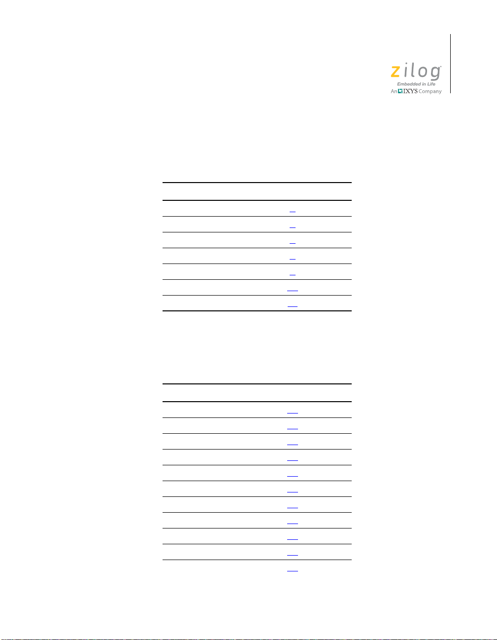
Table 1 lists the default ZAURA RF Wireless Module Shell commands
and references the page each is described on in this manual.
Table 1. Default ZAURA RF Wireless Module Shell Commands
Command Described On Page #
? 4
read 5
write 6
regs 7
remote 8
rvns 10
wvns 11
2
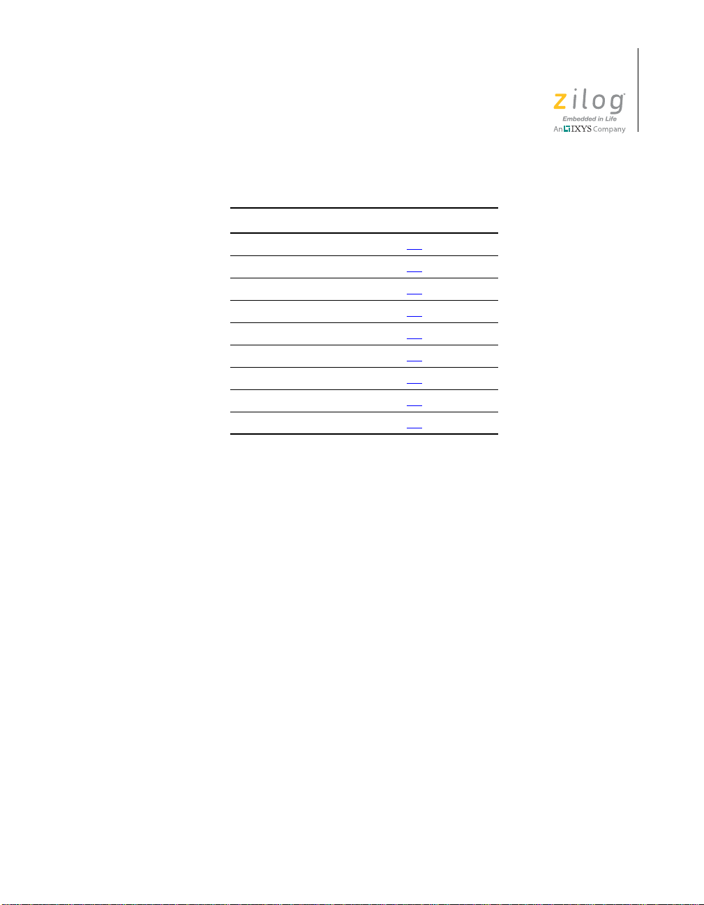
Table 2 lists the optional ZAURA RF Wireless Module Shell commands
and references the page each is described on in this manual.
Table 2. Optional ZAURA RF Wireless Module Shell Commands
Command Described On Page #
addr 12
ch 13
data 14
dst 15
echo 16
filter 17
ipo 18
nid 20
pa 21
per 22
port 24
UM023502-0911 Shell Overview
Page 9
ZAURA RF Module Shell
User Manual
Table 2. Optional ZAURA RF Wireless Module Shell Commands (Continued)
Command Described On Page #
pwr 26
reboot 27
rssi 28
rx 29
sleep 30
stats 31
tx 33
uecho 34
wake 36
3
Default Shell Commands
The default Shell commands listed in Table 1 are each described in this
section, complete with command syntax and examples. These Shell command descriptions begin on the next page.
UM023502-0911 Default Shell Commands
Page 10

? Help
Syntax
?
Example
?
Available Commands
?
read
write
regs
rnvs
wnvs
remote
addr
ch
data
dst
echo
ZAURA RF Module Shell
User Manual
4
The
Help command displays the list of available shell commands for this
node.
UM023502-0911 ?
Page 11

read Read registers
Syntax
read ofs <len>
Example 1
read 10
D6
Example 2
read 10 5
D6 38 28 07 27
ZAURA RF Module Shell
User Manual
5
read command displays a subset of the ZAURA RF Wireless Mod-
The
ule register set. The ofs parameter specifies the zero-based offset of the
first register to read. The optional <len> parameter specifies the number
consecutive registers to read. If <len> is omitted, only the contents of ofs
is displayed. All values must be specified in hexadecimal format.
The ofs parameter must be between
UM023502-0911 read
0x00 and 0x1F.
Page 12
write Write registers
Caution:
Syntax
write ofs data
Example
write 16 aabbccdd
AA BB CC DD D6
write command is used to modify one or more ZAURA RF Wire-
The
less Module registers beginning with ofs. If the data parameter specifies a
single 8-bit value, only register ofs is modified. Otherwise, subsequent
data values will be written to sequential registers.
ZAURA RF Module Shell
User Manual
6
Altering the contents of the radio registers can disrupt – or even disable
– all communication within the ZAURA RF Wireless cell and cause the
application to stop working properly. The
write command is typically
only used for diagnostic purposes.
UM023502-0911 write
Page 13

regs Read all 32 radio registers
Syntax
regs
Example
regs
70 8C 03 03 0C C0 74 5C 3A 8F 72 25 38 C8 13 00
D6 38 38 07 29 00 AA BB CC DD F0 00 3F 23 BE 00
The
regs command displays the contents of all 32 ZAURA RF Wireless
radio registers. It is equivalent to issuing the command
ZAURA RF Module Shell
User Manual
7
read 0 20.
UM023502-0911 regs
Page 14

ZAURA RF Module Shell
remote Issue command to remote node(s)
Syntax
remote cmd <param>
Example 1
remote addr
local address: 1b
Example 2
remote rnvs 0 6
02 11 22 00 00 1B
Example 3
User Manual
8
remote tx ff Hello
Rx Packet: RSSI 8A Pwr -49 dBm
05 FF 1B 00 68 65 6C 6C 6F
Transmit DA FF data: hello
Done transmit
The remote command is used to transmit a shell command to the default
ZAURA RF Wireless target address (DST command). The command is
not echoed on the remote terminal. In Example 3 above, the local node
will send a request to the remote node to issue a transmit request of
"Hello" to the broadcast address. The Remote node’s command inter-
preter will process the shell command (
tx ff Hello) and transmit the
packet. When the local node receives the transmitted packet from the
remote node, it displays the received packet from the remote node.
Prior to initiating a remote shell command, the default ZAURA RF Wireless Module target address should be set to a unique address. If the broadcast address (
UM023502-0911 remote
ff) is used, the node issuing the remote console command
Page 15

ZAURA RF Module Shell
Note:
User Manual
could potentially be flooded with responses unless there is only one other
ZAURA RF Wireless node in the same cell.
Any shell command can be executed remotely . However, be aware that
side effects may prevent further communication. For example, changing
the RF channel used by a remote node will prevent the node that issued the
remote command from receiving any console output from the target.
Executing a command on the Shell of a remote node, and the display of
output generated by such a command through the local Shell when using
the remote command, is only possible if both nodes are configured to use
the DA_SA_CTRL frame format.
9
UM023502-0911 remote
Page 16

ZAURA RF Module Shell
User Manual
rnvs Read one or more configuration Flash
information bytes
Syntax
rnvs ofs <len>
Example
rnvs 0 9
04 11 22 33 44 23 01 00 03
The
rnvs command displays a subset of the ZAURA RF Wireless Mod-
ule configuration information stored in Flash. The ofs parameter specifies
the 0-based offset of the first location to read. The optional <len> parameter specifies the number consecutive memory addresses to read. If <len>
is omitted only the contents of ofs is displayed. All values must be specified in hexadecimal format.
10
The ofs parameter must be between
UM023502-0911 rnvs
0x00 and 0xFF.
Page 17

ZAURA RF Module Shell
User Manual
wnvs Write one or more configuration Flash
information bytes
Syntax
wnvs ofs data
Example
wnvs 2 1234
12 34
The
wnvs command is used to modify one or more Flash memory loca-
tions that contain ZAURA RF Wireless parameters. The ofs parameter
specifies the first location to modify . If the data parameter specifies a single 8-bit value, only the memory location at ofs is modified. Otherwise,
subsequent data values will be written to sequential memory locations.
11
Optional Shell Commands
The optional Shell commands listed in Table 2 on page 2 are each
described in this section, complete with command syntax and examples.
These optional Shell command descriptions begin on the next page.
UM023502-0911 wnvs
Page 18

addr Set/Get local address
Syntax
addr <addr>
Example 1
addr
local address: 23
Example 2
addr 7F
If the
addr command is issued without any parameters, the current
ZAURA RF Wireless node address is displayed. If the <addr> parameter
is specified and it is between
modified and the RF parameters in Flash are updated.
0x01 and 0xFE, the local RF address is
ZAURA RF Module Shell
User Manual
12
UM023502-0911 addr
Page 19

ch Set/Get current channel
Syntax
ch <NewCh>
Example 1
ch
Currently using channel 0
Example 2
ch 3
Switching to Channel 3
Currently using channel 3
ZAURA RF Module Shell
User Manual
13
If the <NewCh> parameter is omitted, the current RF channel is displayed. If the <NewCh> parameter is specified and valid, the radio is configured for the new channel and the RF parameters stored in Flash are
updated. After the RF channel is altered, the node will not be able to communicate with any nodes on the previous channel. This command effectively switches the ZAURA RF Wireless node into a different cell. If the
<NewCh> parameter is specified but invalid, the radio configuration is
not modified. Refer to the ZAURA RF Wireless Module product user
guide that describes your particular module to determine the valid channels.
UM023502-0911 ch
Page 20

data Link console to RF I/O
Notes:
Syntax
data
Example 1
data
Entering DATA mode
console input is sent to remote peer(s) until exit data mode via++
Exiting DATA mode
The ZAURA RF Wireless Module console features two modes of operation: Command Mode and Data Mode. By default, the console is configured for Command Mode, meaning that characters received over UART0
are processed by the local command interpreter. However, when the console is switched to Data Mode via this command, data received over
UART0 is transmitted to the default ZAURA RF Wireless Module target
address (DST command). If the remote device is also operating in data
mode, it sends the data received from the radio over UART0. This action
allows bridging to/from the local UART via RF to/from the remote
UART, e.g.:
ZAURA RF Module Shell
User Manual
14
Local UART RF remote UART
To exit Data Mode and return to Command Mode, press the two consecutive escape characters.
The default ZAURA RF configuration file uses ++ as the escape sequence, but the
value of the
ferent escape character.
ZAURA_RF_DataEscChar
variable can be modified to specify a dif-
While the ZAURA RF Wireless Module console operates in Data Mode, the command interpreter is still able to process commands issued from remote nodes.
UM023502-0911 data
Page 21

ZAURA RF Module Shell
User Manual
dst Set/Get Destination for other commands
Syntax
dst <addr>
Example 1
dst
RF target address: FF
Example 2
dst 6B
The
dst console command is used to display or modify the default
ZAURA RF Wireless Module target address,
ZAURA_RfDest address is the implied target of the remote, data, echo
per console commands. After every Power-On Reset, the dst
and
address is reset to the default value of the
variable defined in
ZAURA_RF_Conf.c.
ZAURA_RF_Dest. This
ZAURA_RfDest configuration
15
UM023502-0911 dst
Page 22

ZAURA RF Module Shell
User Manual
echo Ping/pong message between nodes
Syntax
echo <message>
Example 1
echo
Example 2
echo "hello world"
Tx 1 Rx 1 'hello world'
Tx 2
16
echo command is used to initiate a ping-pong test between two
The
nodes. Prior to issuing the
echo command on both nodes, use the dst
console command to specify the ZAURA RF Wireless nodes address of
the peer device.
On the first node, enter the
echo command without any parameters to
configure the node as the initial responder (pong). On the second device,
issue the
echo command and supply an arbitrary <message> to transmit
to the peer (ping). If the remote receives the <message>, it will echo it
back to the transmitter. Upon receipt of the echo, the transmitter echoes it
back to the remote device. This process continues until the packet is lost
(one side will show a
Tx message but not an Rx message) or a key is
pressed in the terminal program to exit the test.
UM023502-0911 echo
Page 23

filter Set/Get address filter
Syntax
filter <setting>
Example 1
filter
Rx filter level 3
Example 2
filter 1
The
filter command is used to display or modify the current setting of
the radio’s address filter. If the
parameters, the current filter value is displayed. If this command is issued
with a <setting> parameter, the radio’s receive filter is modified and the
filter setting is stored in Flash. The filter can include broadcast
new
packets (a filter value of 3) or exclude broadcast packets (a filter value of 1).
filter command is issued without any
ZAURA RF Module Shell
User Manual
17
UM023502-0911 filter
Page 24

ZAURA RF Module Shell
User Manual
ipo Set/Get Oscillator control configuration
variable
Syntax
ipo <index>
Example 1
ipo
IPO frequency 2 (2764800 Hz)
Example 2
ipo 0
Rebooting...
ZAURA RF Wireless v1.10a Build 11081801
-------------------------------
FW checksum 7C57
18
This
ipo
console command can be used to modify the
configuration variable. The value of the
ZAURA_RF_OscCtrl1
ZAURA_RF_OscCtrl1
variable determines the system clock frequency of the Z8F2480 MCU’s Internal Precision
Oscillator (IPO). The ZAURA RF Wireless Module library can be used with
IPO frequencies from 1.3842 MHz to 11.0592 MHz.
If the ipo command is issued without any parameters, the current IPO
frequency is displayed. If the <index> parameter is specified and contains
a value between 0 and 3, then the value of the
OscCtrl1 configuration
variable in Flash is updated and the system performs a reset procedure to
re-initialize all peripherals with the new system clock frequency.
The UAR T baud rate will be modified if the IPO frequency is changed to
or from the 1.3.824 MHz frequency, as indicated in Table 3.
UM023502-0911 ipo
Page 25

ZAURA RF Module Shell
User Manual
Table 3. UART Baud Rate per IPO Index
UART Baud Rate
IPO Index System Clock (MHz)
0 11.0592 57.6
1 5.5296 57.6
2 2.7648 57.6
3 1.3824 28.8
(kbps)
The lower the IPO frequency, the less current the ZAURA RF Wireless
Module will consume. However, it will also be more difficult to keep pace
with a peer device running at a higher IPO frequency and sending bursts
of data. Zilog recommends operating peer devices at the same IPO frequency.
19
UM023502-0911 ipo
Page 26

nid Set/Get Network ID
Syntax
nid <setting>
Example 1
nid
Network ID: 1122
Example 2
nid B2C4C6E8
The
nid console command displays or modifies the ZAURA RF Wireless
Module network identifier. If the
parameters, the current value of the
parameter is specified and is between 1 and 4 bytes in length, the radio is
reconfigured and the new
radio is not reconfigured and Flash parameters are not modified.
nid is stored in Flash. If the nid is invalid, the
ZAURA RF Module Shell
User Manual
20
nid command is issued without any
nid is displayed. If the <setting>
UM023502-0911 nid
Page 27

ZAURA RF Module Shell
pa transmit constant preambles
Syntax
pa <dummy>
Example 1
Pa
OOOO
Example 2
Pa xx
xOxOx
User Manual
21
pa console command is used to force the transmitter to emit a stream
The
of constant preambles on the current RF channel at the current
level setting. If the
pa command is issued without any parameters, then
Tx power
the radio will continuously emit preambles until a key is pressed on the
terminal program. If a parameter is specified, then regardless of the value
of the parameter, the radio will emit preambles for a period of 1 second
and then stop sending preambles for a period of 1 second. This cycle
repeats such that the radio emits preambles with a 50% duty cycle at
0.5 Hz. While transmitting preambles, the node running the
pa command
may interfere with nearby RF communications and could even prevent
other nodes from being able to communicate at all.
As the
pa command operates, it will display a character on the console
every second. An “O” is displayed if the radio is emitting preambles, and
an “x” is displayed when it is silent. The
pa command terminates when a
key is pressed on the console terminal.
UM023502-0911 pa
Page 28

ZAURA RF Module Shell
User Manual
per Send bursts of 100 test packets to target
Syntax
per <addr>
Example 1
Per
Target 7F should be running 'RX' command
Polling 7F Index 0000 RxCount 100 on cycle 0
Polling 7F Index 0001 RxCount 100 on cycle 1
Polling 7F Index 0002 RxCount 100 on cycle 2
Example 2
22
per 23
Target 23 should be running 'RX' command
Polling 23 Index 0000 ... no response
Polling 23 Index 0000 ... no response
Polling 23 Index 0000 ... no response
per and rx console commands are intended to be used together to
The
test the performance of the link. The node that runs the
per command
sends bursts of 100 packets to the target node. This target node may be
explicitly identified using the <addr> parameter . If an <addr> parameter
is not specified, the performance test frames will be sent to the default
ZAURA RF Wireless Module target address
After transmitting 100 packets, the node running the
RfDest (DST command).
per command polls
the target for a response frame. The objective is to determine how many
performance test frames the target actually received since the last time it
was polled. If there are no link errors, the target response should indicate
that 100 packets were received. If a response is received within approximately 100 ms, the number of test packets received by the remote target is
displayed. In this instance, the transmitter increments an index counter
UM023502-0911 per
Page 29

ZAURA RF Module Shell
User Manual
and sends the next block of 100 packets. If a poll response is not received
after the 100ms time-out, the transmitter will resend the poll request.
This process continues until the operator presses a key on the terminal
program to end the performance test.
23
UM023502-0911 per
Page 30

port Set/Get GPIO pin state
Syntax
Port reg <op value>
Example 1
port e
Port_E initially 20 now 20
Example 2
port e = 40
Port_E initially 20 now 40
Example 3
ZAURA RF Module Shell
User Manual
24
port e ^ 60
Port_E initially 40 now 20
The
port console command can be used to manipulate GPIO output pins.
The
port command requires at least one parameter, reg, that specifies
which Z8F2480 GPIO port is being targeted. Valid values of reg are
through
PEOUT. If the
e, which target the GPIO output registers PAOUT through
<op value> parameters are omitted, then the current set-
a
ting of the GPIO output port is displayed.
The <op value> parameters identify a bit-wise operator to use with the
current value of the port register and the value parameter. Valid
port
operators and their usage are shown in Table 4.
Table 4. port Operator Definitions
Operator (op) Definition
= Assigns value to the target GPIO output port. Equivalent to the “C”
statement: “PxOUT = value;”
UM023502-0911 port
Page 31

ZAURA RF Module Shell
Caution:
Table 4. port Operator Definitions (Continued)
Operator (op) Definition
| Performs a bit-wise OR using the current value of the output port
register and the value parameter. Equivalent to the “C” statement
“PxOUT |= value;”
& Performs a bit-wise AND using the current value of the output port
register and the value parameter. Equivalent to the “C” statement
“PxOUT &= value;”
^ Performs a bit-wise XOR using the current value of the output port
register and the value parameter. Equivalent to the “C” statement
“PxOUT ^= value;”
User Manual
25
Use the port command with caution, because modifying port pins can
cause unexpected behavior.
UM023502-0911 port
Page 32

ZAURA RF Module Shell
pwr Set/Get Transmit Power level
Syntax
Pwr <setting>
Example 1
Pwr
Tx power level 0 (13 dBm)
Example 2
pwr 3
pwr Setting dBm Value
013 dBm
110 dBm
27 dBm
34 dBm
41 dBm
5–2 dBm
6–5 dBm
7–8 dBm
User Manual
26
The
pwr console command is used to display or modify the transmit
power level of the ZAURA RF Wireless Module radio. If the
pwr com-
mand is issued without any parameters, the current transmit power level is
displayed. If this command is issued with a <setting> parameter and the
value is valid (less than 8), the radio’s transmit power level is modified
and the new setting is stored in Flash. If the <setting> parameter is
invalid, the radio’s transmit power level is not modified and the contents
RfParams in Flash is not modified.
of
UM023502-0911 pwr
Page 33

reboot Soft reset of the node
Syntax
reboot
Example 1
reboot
ZAURA RF Wireless v1.10a Build 11081801
-------------------------------
FW checksum 7C57
ZAURA RF Module Shell
User Manual
27
After the
reboot command is issued, the ZAURA RF Wireless node
undergoes a soft reset.
UM023502-0911 reboot
Page 34

ZAURA RF Module Shell
User Manual
rssi Read Receive Signal Strength Indicator
Syntax
rssi
Example 1
rssi
--2D-- RSSI: Ave 2D (–95 dBm) Max 39 (-89 dBm), Min 00 (–105 d Bm)
--2E-- RSSI: Ave 2E (–95 dBm) Max 3B (-88 dBm), Min 24 (–100 dBm)
--31-- RSSI: Ave 2E (–95 dBm) Max 38 (-90 dBm), Min 24 (–100 dBm)
--33-- RSSI: Ave 2E (–95 dBm) Max 3A (-89 dBm), Min 24 (–100 dBm)
--2B-- RSSI: Ave 2E (–95 dBm) Max 3B (-88 dBm), Min 24 (–100 dBm)
--2F-- RSSI: Ave 2E (–95 dBm) Max 3C (-88 dBm), Min 24 (–100 dBm)
--24-- RSSI: Ave 2E (–95 dBm) Max 39 (-89 dBm), Min 24 (–100 dBm)
--31-- RSSI: Ave 2E (–95 dBm) Max 39 (-89 dBm), Min 24 (–100 dBm)
28
After the rssi command is issued, the radio is placed into receive mode
and begins listening to the current channel. During this test, the RSSI
level is sampled 256 times to determine the average, minimum and maximum RSSI value detected. The
rssi command then displays a message
indicating the last RSSI value sampled and the average, minimum and
maximum values from the most recent 256 samples. The RSSI values are
also converted to the approximate receiver power level in dBm. The
rssi
test terminates after a key is pressed on the console terminal program.
UM023502-0911 rssi
Page 35

ZAURA RF Module Shell
User Manual
rx Receive mode for test packets (per
command)
Syntax
Rx
Example 1
Rx
Waiting for packets from peer running 'PER 23' command
....*........
per and rx console commands are intended to be used together to
The
test the performance of the link. The node that runs the
receiver) places the radio in receive mode and waits for the node running
the
per command to send a burst of packets and then query the receiver.
The receiver expects to receive a burst of 100 packets, followed by a poll
request.
rx command (the
29
As the receiver receives test packets from the transmitter, it increments a
packet counter. When a poll packet is received, the receiver sends a
response packet to the transmitter to indicate the number of packets that
have been received since the last time it was polled. If the packet count in
the response is 100, the receiver displays a period (.) on the console. If
fewer than 100 packet were received, an asterisk (*) is displayed. After
the receiver sends the poll response packet, it resets the packet counter to
0 and waits for the next block of 100 packets from the transmitter.
rx test terminates after a key is pressed on the console terminal pro-
The
gram.
UM023502-0911 rx
Page 36

sleep Put node to sleep
Syntax
sleep
Example 1
sleep
Going to sleep...
ZAURA RF Module Shell
User Manual
30
After the
sleep command is issued, the ZAURA RF Wireless node is
placed into a low power state. The unit will remain dormant until an
F2480 Stop Mode Recovery event returns the unit to normal mode. When
sleep command is issued in the default ZAURA RF Demo program
the
SW1
running on the ZAURA Wireless validation board, pressing the
pushbutton or typing a character on the console terminal will reactivate
the Module. When using the sleep command with a custom project any
GPIO port pin configured as a Stop Mode Recovery source can be used to
reactivate the Module.
UM023502-0911 sleep
Page 37

ZAURA RF Module Shell
stats Get RF Statistics for this node
Syntax
stats <clr>
Example 1
Stats
RF Statistics:
Rx Pkts 00000 Bytes 000000000 NoBuf 00000
Rx Ack 00001 Pause 00000 Nak 00000 Retry 00000
Tx Pkts 00001 Bytes 000000005 UR 00000 Busy 00000
Tx Ack 00000 Pause 00000 Nak 00000 Retry 00000
User Manual
31
Example 2
Stats clr
stats console command displays a running total of the number of
The
packets/ bytes sent and received. All values are displayed in decimal format. The statistics can be cleared by issuing the
stats clr command.
The statistics are divided into two sections, receive (Rx) and transmit
(Tx), with similar counters displayed in both groups. Table 5 describes
each of these counters.
Table 5. stats Counter Definitions
Counter Definition
Rx Pkts The number of data packets received from remote devices.
Rx Bytes A cumulative total of bytes received in the data field of all received packets
(headers are not included).
UM023502-0911 stats
Page 38

ZAURA RF Module Shell
User Manual
Table 5. stats Counter Definitions
Counter Definition
Rx NoBuf The number of times the receiver dropped an otherwise valid packet
because no receive buffers were available.
Rx Ack The number of ACK frames received in response to all transmitted SDATA
frames.
Rx Pause The number of times a target node requested this node to PAUSE before
sending another data packet.
Rx Nak The number of SDATA frames transmitted that reached the intended
target but were rejected because of an invalid sequence number.
Rx Retry
Tx Pkts The number of data packets transmitted to remote nodes.
Tx UR The number of failed transmission attempts due to a transmit underrun.
Tx Busy The number of aborted transmissions due to a busy channel (RSSI
Tx Bytes A cumulative total of bytes transmitted in the data field of all transmitted
Tx Underrun The number of failed transmission attempts due to a transmit underrun.
Tx Ack The number of ACK frames transmitted in response to all received SDATA
Tx Pause The number of times this node requested a PAUSE delay after crossing a
Tx Nak The number of times this node rejected a received SDATA frame because
Tx Retry The number of SDATA packets transmitted that required at least one
The number of SDATA packets received that required at least one
retransmission.
sampled above ZAURA_RF_RSSI for ZAURA_RF_CsAttempts times).
packets (header are not included).
frames.
low buffer threshold.
of an invalid sequence number.
retransmission.
32
UM023502-0911 stats
Page 39

tx Send text message
Syntax
Tx dst message <count>
Example
tx 1b hello 3
Transmit DA 1B Data: hello
tx (transmit) command is used to send a text message to a remote
The
node. The target node is specified by the <dst> parameter, which should
be a hexadecimal value between
in range).
ZAURA RF Module Shell
User Manual
33
0x01 and 0xFF (broadcast to all nodes
The message parameter is an arbitrary string of ASCII characters. T o
transmit messages with spaces, enclose the message in quotation marks
(e.g., “message with spaces”). The <count> parameter is optional. If
<count> is omitted, the message will be sent only once. If <count> is
included, it must be between
0x00 and 0xFF. A non-zero value means
that the message will be sent <count> times. If <count> is zero, the message will be transmitted continuously. Continuous transmission terminates after the operator presses a key on the terminal program.
UM023502-0911 tx
Page 40

ZAURA RF Module Shell
User Manual
uecho Set the UART in Echo or No Echo mode
Syntax
uecho <on|off>
Example 1
uecho
UART echo ON
Example 2
uecho off
UART echo OFF
34
The ZAURA RF Wireless Modu le Shell can be configured to echo characters received on UART0 Rx to UART0 Tx. This echo configuration
allows the operator of the console terminal program to see the characters
he or she is typing in the terminal window. However, the terminal program will also typically include a
local echo option in which the termi-
nal program automatically displays characters as they are entered in the
terminal window. Configuring both the PC terminal program and the
ZAURA RF Wireless node to echo UART data will result in two characters being displayed for every entered character, while disabling
echo on
both sides means that the operator will be typing blind.
The default ZAURA RF Wireless Module UART echo setting is con-
trolled by the
ZAURA_RF_UartEcho configuration variable. The value of
this variable can be programmatically modified at run time; it can also be
modified by using the
uecho console command. If the uecho command
is issued without any parameters, it will display the current UART echo
state. To enable UART echo, issue the command
UART echo, issue the command
UM023502-0911 uecho
uecho off.
uecho on. To disable
Page 41

ZAURA RF Module Shell
User Manual
Each time the ZAURA RF Wireless nodes reset, UART echoing returns to
the state defined by the
ZAURA_RF_UartEcho configuration variable.
35
UM023502-0911 uecho
Page 42

ZAURA RF Module Shell
Note:
User Manual
wake Put the node in sleep mode after inactivity
time out
The wake command is not included in the ZAURA RF Shell Library. This
command is defined in the ZAURA RF Demo project to demonstrate how
a user-defined command can be integrated with ZAURA RF Shell commands. This command can only be used with the ZAURA RF Demo program.
Syntax
wake period <message> <target>
36
Example 1
Wake
Wake period 10 seconds - Msg (len 5, dst FF):
'Hello'
Example 2
wake 0
in active mode
Example 3
Wake 3c Hello 1b
Wake period 60 seconds - Msg (len 5, dst 1B):
'Hello'
The default operating mode of the ZAURA RF Wireless Module demo
project is to leave the radio constantly active in receive mode while waiting for console commands. The
UM023502-0911 wake
wake console command can be used to
Page 43

ZAURA RF Module Shell
User Manual
force the device into a low power mode (see “sleep” on page 30) after a
configurable inactivity time out. The ZAURA RF Wireless node will
remain in the low power state until the operator presses the SW1 pushbutton or a character is entered in the terminal program.
If the ZAURA RF Wireless node is brought out of low power mode as a
result of an SW1 action, it will optionally transmit a message to a target
node(s). The message is not transmitted if the ZAURA RF Wireless node
is brought out of low power mode due to console activity. After the
ZAURA RF Wireless node is in the active state, it will start an inactivity
timer. After this timer reaches
period seconds, the device returns to low
power mode. Each time console, SW1 or RF activity is detected while in
active mode, the inactivity timer is reset to 0 to extend the duration of
time that the unit will remain awake.
If the
wake console command is issued without any parameters, the cur-
rent wake settings are displayed. If a time-out period is specified without
<message> and <target> parameters, the ZAURA RF W ireless node will
enter low power mode after the specified time-out period expires and will
not transmit a wake-up <message> when brought out of low power mode
due to SW1 being pressed. If the <message> parameter is specified with-
out a <target> parameter, the wake-up <message> is broadcast to all
nodes when SW1 is pressed. Otherwise, the wake-up <message> is only
sent to the <target> ZAURA RF Wireless node. Any time the time-out
period, wake-up <message> or <target> values are modified, the demo
program updates UserParams in Flash.
37
UM023502-0911 wake
Page 44

Customer Support
To share comments, get your technical questions answered, or report
issues you may be experiencing with our products, please visit Zilog’s
Technical Support page at http://support.zilog.com
To learn more about this product, find additional documentation, or to
discover other facets about Zilog product offerings, please visit the Zilog
Knowledge Base at http://zilog.com/kb
Zilog Forum at http://zilog.com/forum
This publication is subject to replacement by a later edition. T o determine
whether a later edition exists, please visit the Zilog website at http://
www.zilog.com.
ZAURA RF Module Shell
User Manual
38
.
or consider participating in the
.
Zilog Worldwide Headquarters
1590 Buckeye Drive
Milpitas, CA 95035
Telephone: 408.513.1500
Fax: 408.365.8535
www.zilog.com
Document Disclaimer
Zilog is a registered trademark of Zilog Inc. in the United States and in other countries. All other products and/
or service names mentioned herein may be trademarks of the companies with which they are associated.
©2011
Zilog, Inc. All rights reserved. Information in this publication concerning the devices, applications, or
technology described is intended to suggest possible uses and may be superseded. Zilog , INC. DOES NOT
ASSUME LIABILITY FOR OR PROVIDE A REPRESENTATION OF ACCURACY OF THE
INFORMATION, DEVICES, OR TECHNOLOGY DESCRIBED IN THIS DOCUMENT. Zilog ALSO
DOES NOT ASSUME LIABILITY FOR INTELLECTUAL PROPERTY INFRINGEMENT RELATED IN
ANY MANNER TO USE OF INFORMATION, DEVICES, OR TECHNOLOGY DESCRIBED HEREIN OR
OTHERWISE. Except with the express written approval of Zilog, use of information, devices, or technology
as critical components of life support systems is not authorized. No licenses are conveyed, implicitly or
otherwise, by this document under any intellectual property rights.
UM023502-0911 Customer Support
 Loading...