

Page 1

,
,.
_/
,-
,
Zilog
Page 2

03-3199-01
March 1982
Copyright
of
this
system,
mechanical,
prior
The
written
information
without
Zilog
assumes
other
circuit
1981
publication
or
transmitted,
photocopying,
notice.
than
circuitry
patent
by
Zilog,
may
permission
in
this
no
responsibility
licenses
Inc.
be
reproduced,
in
any
recording,
of
Zilog.
publication
embodied
are
implied.
All
form
for
in
rights
or
is
the
a
Zilog
reserved.
stored
by
or
otherwise,
subject
use
product.
any
of
No
in
a
retrieval
means,
without
to
change
any
circuitry
No
part
electronic,
the
other
Page 3

NOTICE
TO
OWNER
,~
FEDERAL
COMMUNICATIONS
COMMISSION
RADIO
FREQUENCY
INTERFERENCE
STATEMENT
Warning:
This equipment generates, uses, and can radiate radio frequency energy and if not
installed and used
in
accordance with the instructions manual. may cause interference to
radio communications. As temporarily permitted by regulation it has not been tested for
co.,,-
pliance
with the limits for Class A computing devices pursuant to Subpart J of Part
15
of
FCC
Rules. which are designed to provide reasonable protection against such interference. Operation of this equipment
in
a residential area
is
likely to cause interference in which case the
user at his own expense will be required to take whatever measures may be required to
cor-
rect the interference.
Page 4

Page 5

USER
i
Zilog
SYSTEf\I
8000
USER
l-lANUAL
PRELIMINARY
VERSION
The
information
contained
in
this
draft
may
undergo
changes,
both
in
content
and
organization,
before
arriving
at
its
final
form.
Zilog
USER
i
Page 6

USER
Zilog
USER
ii
Zilog
ii
Page 7

USER
iii
Zilog
USER
PREFACE
This
manual
provides
an
introduction
and
user
information
for
the
ZEUSm
Operating
System
used
with
the
Zilog
System
8000™
Detailed
description
is
given
for
system
features,
including
the
programming
environment,
the
Monitor
Program,
and
Monitor
I/O
procedures.
This
manual
is
organized
by
sections,
each
section
representing
a
major
component
that
will
familiarize
the
user
with
the
system.
SECTION
1
General
Description
--
Describes
the
System
8000,
including
system
features
and
characteristics.
2
Programming
Environment
--
Provides
hardware
and
software
overviews
of
the
system.
3
System
8000
Monitor
Program
--
Introduces
the
Mon-
itor
Program
and
explains
the
basic
debugging
com-
mands,
I/O
controls,
and
upload/download
software.
4
Monitor
Program
I/O
Procedures
--
Introduces
the
I/O
procedures
used
with
the
Monitor
Program.
APPENDIX
A
Glossary
--
Lists
the
most
important
terms
and
acronyms
introduced
in
this
manual.
For a better
understanding
of
the
system
hardware
components
and
operating
system,
the
user
is
encouraged
to
read
the
following
manuals:
Title
~
Number
ZEUS
Reference
Manual
03-3195
ZEUS
Utilities
Manual
03-3196
ZEUS
System
Administrator
Manual
03-3197
System
8000
Hardware
Reference
03-3198
Manual
System
8000m and
ZEUSm are
registered
trad~marks
of
Zilog,
Inc.
Zilog
iii
Page 8

USER
Zilog
USER
iv
Zilog
iv
Page 9

USER
(
v
Zilog
USER
TABLE
OF
CONTENTS
SECTION 1
GENERAL
DESCRIPTION
•••••••.•••••••••••••••
1
1.1
Introduction.
• • • • • • • • • • • • • • • • • • • • • •
••
1
1.2
System
Environment
•••••••••••••••••••
1
1.3
System
Characteristics
•••••••••••••••
3
1.4
Winchester
Disk
Performance
•••••••••
5
1.5
Cartridge
Tape
Drive
Performance
•••••
6
1.6
ADM-31
Data
Display
Terminal
Performance
..........................
6
SECTION 2
PROGRAMMING
ENVIRONMENT
•••••••••••••••••••
9
2.1
Introduction
•••••••••••••••••••••••••
9
2.2
Hardware
Configuration
•••••••••••••••
9
2.2.1
2.2.2
2.2.3
2.2.4
2.2.5
Microprocessor
••••••••••••••••
9
Winchester
Disk
Drive
•••••••••
12
Cartridge
Tape
Drive
••••••••••
12
ADM-31
Data
Display
Terminal
••
12
Communication
Ports
•••••••••••
16
SECTION 3
S8000
~~ONI'l'0R
PROGRAf.l
•••••••••••••••••••••
19
3.1
Introduction
•••••••••••••••••••••••••
19
3.2
Monitor
Program
Debug
Environment
••••
19
3.3
Monitor
Program
•••••••••••••••.••••••
20
3.3.1
Monitor
Mode Commands
••.••••••
21
3.3.2
Upload/Download
Mode
Commands
••••••••••••••••••••••
28
3.4
System
Parameters
••••••••••••••••••••
31
SECTION 4
MONITOR
I/O
PROCEDURES
•••••••••••••••••••
35
4.1
4.2
Introduction
.........................
35
I/O
Procedures
. . . . . . . . . . . . . . . . . . . . . . .
35
APPENDIX A GLOSSARY. • • • • • • • • • • • • • • • • • • • • • • • • • • • • • •
••
39
Zi10g
v
Page 10

USER
vi
Zilog
USER
LIST
OF
ILLUSTRATIONS
Figure
1-1
S8000
Basic
System
Configuration
•••••••••••••••
2
1-2
Processor
~lodule
Controls
and
Indicators
••.••••
4
2-1
S8000
Functional
Block
Diagram
•••••••••••.•••.•
10
2-2
Peripheral
Module
Hardware
Components
••••.•••••
11
2-3
ADM-31
Data
Display
Terminal
Keyboard
••.•••••••
14
2-4
ADM-31
Keyboard
Special-Purpose
Keys
•••••••••••
15
2-5
Communication
Ports
•••••.••.••.••••••••••.•••••
17
LIST
OF
TABLES
Table
3-1
Program
Status
Area
•••.•••••••••••••••••••..•••
33
3-2
System
Hardware
I/O
Port
Addresses
•••••••••.•.•
34
Zilog
vi
Page 11

~
\,
USER
1
Zilog
USER
SECTION 1
GENERAL
DESCRIPTION
1.1
Introduction
The
Zilog
S8000
System
(Figure
1-1)
is
a
high
performance
microcomputer
system
based
on
th~
Z8001A
16-bit
microproces-
sor.
Program
development
and
text
processing
are
accom-
plished
with
the
ZEUS
Operating
System.
Supporting
up
to
16
users,
the
system
develops
code
for
all
Zilog
CPUs.
This
section
is
a
general
description
of
the
S8000.
1.2
System
Environment
The
S8000
uses
Winchester
disk
storage
and
supports
a
com-
munication
interface
with
other
ZEUS-based
systems,
emula-
tion
devices,
and
development
modules.
The
58000
provides
comprehensive
software
development
and
documentation
tools
to
maximize
programmer
productivity
and
documentation
qual-
ity.
It
includes
the
following
features:
~
A 6
MHz
Z8001A
16-bit
microprocessor
~
256K
bytes
of
error-correcting
memory
~
A
32-bit
ZBI(TM)
backplane
with
an
8-megabyte/
second
bandwidth
~
Intelligent
Z80B-based
controllers
for
disk
and
tape
drives
~
A
24-megabyte
(unformatted)
eight-inch
Winchester
disk
drive
~
A
17-megabyte
(unformatted)
cartridge
tape
drive
~
ZEUS
multi-user,
multitasking
operating
system
The
following
hardware
options
are
also
available:
~
Additional
256K-byte
memory
boards
for
up
to
1.5
megabytes
of
error-correcting
memory
$
Up
to
four
24-megabyte
Winchester
drives
$
Up
to
eight
additional
serial
I/O
ports
Zilog
1
Page 12

USER
Zilog
USER
Figure
2
1-1.
S8000
Basic
Zilog
System
Configuration
2
Page 13
USE~
3
Zilog
USER
$
Up
to
four
l7-megabyte
cartridge
tape
drives
$
Character
and
line
printers
The number
of
controls
and
indicators
have
been
minimized
to
facilitate
system
use.
Only
the
keylock
ON/OFF
switch,
the
RESET
and
START
switches,
and
the
AC
power
switch
are
neces-
sary
to
power up
and
maintain
the
S8000.
Refer
to
Figure
1-2
for
control
and
indicator
locations.
Controls
for
the
optional
Lear
Siegler
ADM-3l
Data
Display
Terminal
include
a
brightness/contrast
control
knob
and
an
AC
power
ON/OFF
switch.
The
resources
of
the
S8000
are
controlled
by
the
ZEUS
Ker-
nel.
The
Kernel
or
the
operating
system
provide
process
management,
file
management,
input/output
(I/O)
processing,
and
increased
program
functionality
with
compatible
file,
device,
and
interprocess
I/O.
ZEUS
is
a
multi-user,
multitasking
operating
system
consist-
ing
of
a
hierarchical
file
system
for
efficient
file
organi-
zation
and a comprehensive
command
language.
A
communica-
tion
program
allows
the
S8000
to
interface
with
other
ZEUS
or
UNIX-based
systems.
Also,
with
ZEUS,
it
is
possible
to
communicate
with
emulation
devices
and
development
modules.
ZEUS
development
tools
include
extensive
language
capabili-
ties
such
as
C,
Pascal,
PLZ/SYS, PLZ/ASM, a
compiler-writing
system,
and a general
purpose
macroproCessor.
Additional
enhancements
to
the
development
system
include
a
full
CRT-
oriented
text
editor,
text
processing,
spelling
error
detec-
tion,
and
document
formatters
for
the
optional
printers.
1.3
System
Characteristics
Processor:
CPU
Clock
Frequency:
I/O:
Baud
Rate:
Segmented
48-pin
Z8001A
CPU
5.5
MHz
Eight
RS-232C
serial
I/O
ports
and
one
parallel
printer
port
From 110
to
19,200
baud
(set
by
software)
Zilog
3
Page 14

USER
Zilog
USER
LOCK
eON
D
RESET
D
START
POWER
USER
DMA
00155
Figure
1-2.
Processor
Module
Controls
and
Indicators
4
Zilog
4"
Page 15

USER
(
5
Front
Panel:
Rear
Panel:
Domestic
Power:
International
Power:
Environmental:
Cabinet
Size:
Cabinet
~leight:
Zilog
USER
Cutouts
for
keylock
ON/OFF
switch,
RESET
switch,
and
START
switch.
Translucent
plastic
for
three
indi-
cator
lamps:
POWER
(+SV
DC),
USER
(CPU
is
in
normal
state),
and
DMA
(CPU
is
giving
up
the
bus
for
Direct
Memory
Access
devices)
Eight
RS-232C
serial
I/O
ports,
a
parallel
I/O
port
for
a
printer,
a
50-pin
connector
for
the
DEI
car-
tridge
tape
unit
interface,
a
40-
pin
connector
for
the
Winchester
disk
drive
interface,
and
two
spare
37-pin
connectors
for
the
terminal
expansion
option
l17Vac
+10%
-20%,
single
phase,
60
Hz.
Current:
lOA
max.
(sustained),
l5A
max.
(surge)
220Vac +10
-20%,
single
phase,
50
Hz. Cur
rent:
SA
max.
(sustained),
8A
max.
(surge)
Operating
temperature:
50
degrees
F (10
C)
minimum
104
degrees
F (40
C)
maximum
Relative
humidity:
80%
noncondensing
Height:
l-I7idth:
Depth:
33
inches
(84
crn)
19
inches
(48
crn)
24
inches
(61
crn)
Approximately
132
pounds
(60 kg)
1.4
Winchester
Disk
Performance
Rotation
speed:
Power
On
to
ready
time:
Average
random
positioning
time:
Number
of
surfaces:
Tracks
per
surface:
Sectors
per
track:
Zilog
3600
RPr1
15
seconds
42
MS
")
...
600
24
5
Page 16
USER
6
Zilog
USER
Bytes
per
sector:
512
Data
transfer
rate:
SOIK
bytes/second
1.5
Cartridge
Tape
Drive
Performance
Cartridge:
ANSI
X3.55 -1977
300
ft.
or
450
ft.
Tape
length
Speed
Read/Write
(rewind):
30
ips
(90
ips)
Tracks:
4
Recording
density:
6400 BPI
1.6
ADM-3l
Data
Display
Terminal
Performance
DISPLAY
Refresh
Rate:
Character
Set:
KEYBOARD
FUNCTIONS
Keyboard:
Cursor
Control:
Edit
Keys:
Function
Command
Keys:
Special
Purpose
Keys:
TRANSlo1ISS
ION
MODES
Interface:
Data
Rate:
60
Hz
or
50 Hz,
depending
on
line
frequency
128
ASCII
characters
(uppercase,
lowercase,
and
control
characters)
26-letter
alphabet
with
uppercase
and
lowercase,
numeric
0
through
9
Individual
cursor
control
keys
Character
insert,
character
delete,
line
insert,
line
delete,
line
erase,
page
erase,
and
clear
ESCape,
BREAK,
PRINT,
SEND
LINE,
SEND
PAGE,
TAB/BACK
TA.B,
NEvI
LINE
I
and
FUNCTION
RETURN,
CTRL
(control),
and
RUB
RS-232C
current
port
Variable
Zilog
point-to-point
loop;
RS-232C
"-~--
or
20mA
EXTENSION
6
Page 17
USER
Parity:
POWER
Standard:
Optional:
Heat
Dissipation:
Environmental:
7
Zilog
USER
None
11SVac,
60
Hz
230/240Vac,
50
Hz
222
BTU/HR
Operating
temperature:
41
to
122
degrees
F
(5
to
50
C)
Relative
humidity:
5%
to
95%
without
condensation
Zilog
7
Page 18

USER
Zilog
USER
8
Zilog
8
Page 19

USER
Q
Zilog
USER
SECTION 2
PROGRAr.nUNG
ENVIRONHENT
2.1
Introduction
The
S8000
System
uses
a
zaooo
microprocessor-based
operating
system
to
perform
software
development
tasks.
This
section
provides
the
basis
for
all
later
discussions
of
Monitor
Pro-
gram
applications
and
I/O
procedures.
The
S8000
Monitor
sets
software
breakpoints
for
program
debugging,
and
includes
I/O
control,
interface
software
for
use
with
a
serial
interface
to
a
remote
computer
system,
and
the
primary
bootstrapper
used
to
bring
the
system
up.
2.2
Hardware
Configuration
The
following
paragraphs
briefly
describe
the
major
charac-
teristics
of
the
S8000
hardware.
Detailed
general
installa-
tion
and
maintenance
information
is
contained
in
the
S8000
Hardware
Reference
Manual.
Figure
2-1
illustrates
the
func-
tional
relationship
of
the
S80nO
hardware
components.
2.2.1
Microprocessor
The
architectural
resources
of
the
Z8000
CPU
include
sixteen
16-bit
general-purpose
registers,
seven
data
types
ranging
from
8-bit
to
32-bit
long
words
and
byte
strings,
eight
user-selectable
addressing
modes,
and
110
distinct
instruc-
tion
types.
The
CPU
can
address
up
to
16
megabytes
in
128K
byte
segments
(64K
bytes
of
data
and
64K
bytes
of
instruc-
tion).
Moreover,
more
than
90%
of
the
instructions
can
use
any
of
five
main
addressing
modes,
with
8-bit
byte,
16-bit
word,
and
32-bit
long
word
data
types.
The
CPU
has
two
operating
modes,
system
and
normal
(user),
that
keep
operating
system
and
applications
programming
separate,
as
in
computer
systems.
This
separation
of
CPU
resources
promotes
the
integrity
of
the
system,
since
pro-
grams
operating
in
normal
mode
cannot
access
those
aspects
of
the
CPU
that
deal
with
time-dependent
or
system
interface
events.
Zilog
9
Page 20

USER
Zilog
USER
UP
TO
3 ADDITIONAL DRIVES
/
~
I I I
I I I
,--------,
,...--------,
....
'--------..,
I
,...
.....
-------....,
I
r.L..-------,
I I
,...'--------.....,
I I
I I
I I I .
I I I
ADDITIONAL
II
ADDITIONAL
8 SERIAL
PARALLEL DISK
ILJ
TAPE
I L I
8 SERIAL PARALLEL
1/0 PORTS
PORT
DRIVE(S)
LJ
DRIVE(S)
LJ
~
I/O PORTS PORT
J
J
...t.
,..
.J!
;:..
...t.
,..
...t.
r--
...t.
,...
...t.
,...
DISK DRIVE
TAPE DRIVE
I/O BUS
1/0 BUS
INTERFACE
INTERFACE
11
...t.
::..
'(40·PIN FLAT
(50·PIN FLAT
RIBBON CABLE)
RIBBON CABLE)
~
-..:
7-
-..:
7-
7"-
SECONDARY
WINCHESTER
CARTRIDGE
SERIAL
CPU
DISK
TAPE
BOARD
CONTROLLER
CONTROLLER
J:
;::..
...:;
;::..
...t.
i'"
7"-
"'<
7"-
-..:
7"-
2
Z·BUS
BACKPLANE
INTERCONNECT
(ZBI)
"1
...t.
,...
,--------.,
,...
.....
-------.,
I
r
......
-------.,
I I
UP
TO
5 ADDITIONAL
~
[
....
-------,
I I I 256K
OR
1 MEGABYTE
,
-------.,
I I I I MEMORY BOARDS
I
I I I I
I
I.
I
I.J
ECC MEMORY
ECC MEMORY
I I
i-J
I
i-~
CONTROLLER
256K BYTE
i-J
J
...t.
1
f""
32·BIT
ECC
MEMORY BUS
~
~ ~
;:
~
Figure
2-1.
S8000
Functional
Block
Diagram
10
Zilog
10
Page 21

USER
Zilog
USER
PROCESSOR
MODULE
CARTRIDGE
TAPE DRIVE
PERIPHERAL
MODULE
STORAGE
COMPARTMENT
\.
•
Figure
11
2-2.
Peripheral
Zilog
Module
Hardware
Components
11
.
Page 22

USER
12
Zilog
.
USER
2.2.2
Winchester
Disk
Drive
The
hard
disk
subsystem
consists
of
a
24-megabyte
eight-inch
Winchester
disk
drive
that
interfaces
with
an
intelligent
ZaOB-based
disk
controller.
A
formatted
disk
is
capable
of
retaining
up
to
22
megabytes
of
user
process
data.
The
Winchester
disk
drive,
which
is
housed
in
the
peripheral
module
(Figure
2-2),
provides
rapid
access
to
the
ZEUS
file
'system
which
is
used
for
program
development.
2.2.3
Cartridge
Tape
Drive
The
cartridge
tape
drive
can
be
used
for
loading
the
ZEUS
Operating
System,
selective
file
storage,
high
speed
pro-
gram
and
data
file
back-up
to
the
Winchester
disk
drive,
and
for
executing
standalone
system
diagnostics.
The
control
of
the
tape
drive
is
provided
by
a
ZaOB-based
cartridge
tape
controller,
located
in
the
processor
module.
Up
to
17.2
megabytes
of
unformatted
data
or
14
megabytes
of
formatted
data
can
be
stored
on a 450-foot
tape.
2.2.4
ADM-31
Data
Display
Terminal
The
optional
data
display
terminal
is
the
primary
bidirec-
tional
data
interface
between
the
user
and
the
system.
The
display
screen
is
a
12-inch
diagonal
CRT
with
a
graphics
matrix
of
80
characters
per
line
by
24
lines.
All
128
printable
ASCII
characters
can
be
displayed
on
the
screen.
The
terminal
keyboard
(Figure
2-3)
is
similar
to
that
of
a
standard
typewriter
with
the
addition
of
special-purpose
keys
(Figure
2-4)
to
facilitate
command
execution.
The
fol-
lowing
paragraphs
describe
the
function
of
the
special-
purpose
keys:
Return~.
Commands
are
read
by
the
ZEUS
Operating
System
character-by-character
as
they
are
entered.
The
command
is
executed
only
after
the
return
key,
labeled
RETURN,
is
pressed.
Control~.
The
control
key,
labeled
CTRL,
generates
and
sends
control
instructions
to
the
terminal
during
command
execution.
Any
character
that
is
typed
with
the
CTRL
key
pressed
is
transparent
to
the
user,
but
is
recognized
by
the
CPU.
For
example,
to
slow,
down
or
temporarily
interrupt
data
transmission
to
the
terminal
without
permanently
halt-
ing
execution
of
a
command,
enter
control-~
by
typing
~
Zilog
12
Page 23

USER
13
Zilog
USER
while
holding
down CTRL.
This
freezes
the
screen.
To
re-
start
transmission,
enter
control-g.
This
sequence
is
used
to
display
data
a
few
lines
at
a
time.
Zilog
13
Page 24

USER
14
Zilog
FORMAT KEYS
ALPHANUMERIC KEYBOARD
TRANSMISSION CONTROL
KEYS
CURSOR CONTROL KEYS
Figure
2-3.
ADM-31
Data
Display
Terminal
Keyboard
Zilog
USER
14
NUMERIC
KEYPAD
Page 25

USER
zilog
USER
Figure
2-4.
15
ADM-31
Keyboard
Zilog
Special-Purpose
Keys
15
Page 26

USER
16
Zilog
USER
Ella~.
This
special-purpose
key,
labeled
RUB,
stops
the
execution
of
a command
before
it
reaches
completion.
After
successfully
stopping
the
command
execution,
the
ZEUS
Operating
System
responds
with
a new
prompt
(%).
2.2.5
Communication
Ports
The S8000
communicates
with
peripheral
devices
that
are
com-
patible
with
an
RS-232C
interface.
The
physical
interface
to
the
eight
serial
I/O
ports,
the
par-allel
printer
port,
and
the
two
terminal
expansion
ports
is
with
the
connectors
located
on
the
rear
of
the
processor
module.
Figure
2-5
shows
the
location
of
the
communication
ports.
The
Winchester
disk
drive
and
the
cartridge
municate
with
their
respective
controllers
tors
located
on
the
rear
of
the
processor
modules.
Zilog
tape
drive
com-
by
using
connec-
and
peripheral
16
Page 27

USER
zi10g
USER
SERIAL 1/0
PORT"TIV 5
TIV6---TIV7
TERMINAL
EXPANSION
TERMINAL
EXPANSION
WINCHESTER
DISK DRIVE
CARTRIDGE
TAPE
DRIVE
WINCHESTER
DISK DRIVE
___
___
___
1
2
---...;;::::=
___
___
___
_
_
..;:;::::::;;:
....;
_
_
'--"'.=
.....
'L
1/0 PORT
:"'CI~NSiOLE
PROCESSOR
MODULE
PERIPHERAL
MODULE
Figure
17
2-5.
S8000
Zilog
Communication
Ports
17
Page 28

USER
Zilog
USER
18
Zilog
18
Page 29

USER
19
Zilog
USER
SECTION
3
S8000
r-mNITOR
PROGRAl-1
3.1
Introduction
The S8000
Monitor
Program
includes
basic
debugging
commands,
I/O
control,
and
interface
software
for
use
with
a
serial
interface
to
a
remote
computer
system.
Detailed
interfacing
procedures
are
found
in
the
S8000
Hardware
Reference
r·lanual
(03-3198)
•
3.2
Monitor
Program
Debu~
Environment
The
Moniter
Program
sets
software
breakpoints
for
program
debugging.
A
breakpoint
is
a command
that
interrupts
or
stops
program
execution
at
a
specified
address
in
the
pro-
gram.
The
address
specified
in
the
breakpoint
is
the
address
of
the
instruction.
When
encountered
during
pro-
gram
execution,
the
breakpoint
suspends
execution
of
the
user's
program
and
saves
all
registers,
program
counters
(PC),
and
the
flag
control
word
(FCW)
in
the
memory
area
provided.
It
then
displays
a
message
reporting
the
break
and
the
address
where
it
occurred.
-
Any
number
of
breakpoints
can
be
set
manually
by
setting
the
desired
breakpoint
address
to
%7FOO
(%
indicates
the
address
is
in
hex
notation).
This
interrupts
the
executing
program
and
jumps
(traps)
to
the
breakpoint
procedure.
The
break-
point
must
be
located
at
an
even
address.
When
the
break-
point
is
no
longer
required,
the
original
instruction
must
be
manually
restored.
The
BREAK
command
saves
the
address
where
the
breakpoint
is
being
set
and
the
instruction
that
it
is
replacing.
When
the
breakpoint
is
cleared,
the
instruction
is
automatically
restored.
The
BREAK
command
also
stores
a
repetition
counter,
n.
Execution
is
not
suspended
until
the
nth
time
this
breakpoint
is
encountered
unless
another
breakpoint
is
encountered
first.
The
following
restrictions
on
the
user
program
are
necessary
to
set
breakpoints:
1.
The
program
must
be
able
to
execute
with
inter-
rupts
enabled
after
encountering
the
breakpoint.
Zilog
19
Page 30
USER
20
Zilog
USER
2.
The
program
should
not
be
timing-dependent
because
there
will
be some
timing
distortion
each
time
the
breakpoint
is
encountered.
3.
The
user
program
must
not
use
Channel
3
of
the
Z80A
Counter
Timer
Circuit
(CTC),
because
it
is
used
to
implement
the
multiple
execution
feature.
4.
The
breakpoint
cannot
be
within
an
interrupt
pro-
cedure
entered
by
an
interrupt
from
Channels
0
through
2
of
the
Z80A
CTC.
The
BREAK
and
the
NEXT
commands
use
instruction
modification
and
the
interrupt
system.
Therefore,
the
program
being
debugged
cannot
be
in
the
PROM
area
and
cannot
involve
modifications
of
the
interrupt
status.
Any
set
breakpoints
must
be
cleared
before
a new
program
is
loaded
from
the
S8000;
otherwise,
previously
set
breakpoints
continue
to
operate
on
the
new
program
during
debugging.
The
user
stack
is
used
whenever a JUMP
or
GO
command
is
exe-
cuted.
The command
must
be
set
to
some
address
within
writ-
able
memory.
If
the
JUMP
or
GO
address
has a system
break-
point
set,
the
execution
of
the
instruction
immediately
fol-
lowing
the
JUMP
or
GO
does
not
cause
suspension
of
execu-
tion.
Subsequent
executions
suspend
the
breakpoint
to
per-
mit
breaking
and
continuing
execution
without
resetting
the
breakpoint.
.
3.3
Moniter
Program
The
following
conventions
are
used
in
command
descriptions:
< >
Angle
brackets
enclose
descriptive
names
for
the
quantities
to
be
entered.
Square
brackets
denote
optional
quantities.
A
bar
denotes
an
OR
condition.
For
example,
WIB
means
either
w
or B can
be
used.
Underscore
indicates
user
input.
(CR)
Return
and
line
feed.
Apply
the
following
when
entering
commands
and
options:
1.
All
commands
and
options
must
be
entered
in
upper-
case.
Zilog
20
Page 31

USER
21
Zilog
USER
2.
Commands
can
be
abbreviated
to
their
first
letter.
3.
Numbers
are
represented
in
hex
notation
and
must
begin
with
a
numeric
digit.
4.
The
first
character
typed
on a new
line
identifies
which
command
is
being
invoked.
If
an
invalid
character
is
entered,
a
"1"
is
displayed,
prompt-
ing
a new command.
5.
Addresses
are
specified
by
an
optional
segment
number
in
angle
brackets,
followed
by a
hex
address.
For
exarr.ple,
<00>4000 <00>0 <01>F800.
3.3.1
Monitor
Mode
Commands
Summary
of
Commands
in
Monitor
Mode
DISPLAY
REGISTER
BREAK
NEXT
GO
JUl1P
FILL
IOPORT
~10VE
COIvlPARE
QUIT
PARAMETERS
<address>
[<I
of
lcng
words/words/bytes>]
[LIWIB]
Display
and
alter
memory
[
<register
name> ]
Display
and
alter
registers
<address>
[ <n>]
Set
and
clear
breakpoint
[
<n>
]
Step
instruction
Branch
to
last
PC
<address>
Branch
to
address
<addressl>
Fill
memory
<address2>
<port
address>
[WIB]
I/O
port
read/write
<addressl>
<address2>
Move
memory
block
<addressl>
<address2>
Compare memory
block
Enter
Transparent
Mode
Zilog
<data>
<n>
21
Page 32

USER
22
Zilog
USER
SIOPORT
TEST
ZBOOT
<port
address>
[WIB]
SIO
port
read/write
Enter
Test
Mode
[DIT]
Read a
5l2-byte
program
from
disk
or
tape
and
execute
NOTE
All
outputs
in
Monitor
Mode
can
be
suspended
with
XOFF
(%13)
control-s
and
resumed
with
XON
"(%11)
control-q.
COklMAND
DESCRIPTIONS
DISPLAY
Syntax
DISPLAY
<address>
<#
of
long
words/words/bytes>
[LIWIB]
Description
This
command
displays
at
the
terminal
the
contents
of
speci-
fied
memory
locations
starting
at
the
given
address,
for
the
given
number
of
bytes.
If
the
LlwlB
parameter
is
specified,
the
contents
of
the
memory
locations
are
displayed
in
hex
notation
and
as
ASCII
characters.
If
the
LlwlB
parameter
is
not
specified,
the
memory
loca-
tions
are
displayed
one
at
a
time,
with
an
opportunity
to
change
the
contents
of
each
location.
For
each
location,
the
address
is
displayed,
followed
by
the
contents
of
LlwlB
and a space.
To
change
the
co~tents
at
a
given
location,
enter
the
new
contents
in
the
form
long
wordlwordlbyte.
If
RETURN
is
pressed,
either
alone
or
after
the
new
contents,
the
next
sequential
location
is
displayed.
Entering
a
"Q"
(for
QUIT),
followed
by a
RETURN
terminates
the
command.
Example
Display
memory
starting
at
%5200
for
ten
words.
<
D.
.5..2.rul
lJ!
(
CR)
> .
<00> 5200
1808
FE2B
2004
D923
7ED9
CD35
2238
OAED
*
...
+
••
#
•••
5"8
••
*
<00> 5208 6F23
ED6F
2BIE 0118
EDD9
2218 14D9 5778
*0#
.0+
•••
H
•••
Wx*
Zilog
22
Page 33

USER
(
23
Zilog
Example
Display
memory
starting
at
%5200
for
10
bytes.
<.0
.5.2M.
l.Q. ~ (
CR)
>
<00> 5200
18
08
FE
2B
20 04
D9
23
7E
D9
tCD 35 22
38
OA
ED
*
...
+
••
1
•••
5"8
••
*
Example
Display
memory
location
%5200
and
alter
its
contents.
<.o.5..2.QQ
(CR»
<00> 5200
1808
<1922
(CR)
<00> 5201
FE2B
«CR»
<00> 5202 2004
<Q(CR»
REGISTER
Syntax
REGISTER
[<register
name>]
Description
USER
The
REGISTER
command
is
used
to
examine
or
modify
a
speci-
fied
register.
The
following
register
names
can
be
used
in
the
command:
1.
Any
of
the
sixteen
16-bit
registers
named
RO,
Rl,
R2
•••
R15.
2.
Any
of
the
sixteen
8-bit
registers
named
RHO,
RLO,
RHl, RLI
•••
RH7, RL7.
3.
Any
of
the
eight
32-bit
registers
named
RRO,
RR2,
RR4
•••
RR14.
4.
Program
counter
register
named RPC.
NOTE
The new
contents
of
the
program
counter
must
be
given
in
even
hex
numbers.
5.
Flag
and
control
word named RFC.
If
no
register
name
is
given,
all
registers
RO,
Rl,
R2
•••
R15
PC
and
Few
are
displayed.
If
a
register
name
is
given,
the
specified
register
name
is
displayed,
followed
by ~ space.
To
change
the
contents
of
that
register,
enter
the
new
contents
followed
by a
Zilog
23
Page 34

USER
24
Zilog
USER
RETURN,
either
alone
or
after
the
new
contents.
This
displays
the
next
register.
A "Q"
followed
by
a
RETURN
terminates
the
command.
Exam~le
Display
all
registers.
<R
(CR)
RO
Rl
R2
R3
R4 R5
R6
0000 0000 0000 0000 0000
0000
0000
R6 R7 R8 R9
RIO
Rll
R12
0000
0000
0000 0000
0000 0000 0000
R13 R14
R15
RPC RFC
0000
0000
0000
0000 0000
Exam~le
Display
32-bit
word
register
RR4
and
alter
its
contents.
<R
RR4
(CR)
RR4
00000000
<A257FFFF
(CR)
RR6
00000000
<Q
(CR»
BREAK
Syntax
BREAK
<address>
[<n>]
Descri~tion
The
BREAK
command
sets
a
breakpoint
at
a
given
even
address
after
clearing
any
previously
set
breakpoint.
If
<n>
is
given,
program
execution
is
not
interrupted
until
the
nth
time
the
breakpoint
instruction
is
encountered
«n>
is
in
the
range
%l-%FFFF).
If
<n>
is
not
given,
1
is
assumed.
If
the
BREAK
command
is
issued
with
no
parameters,
any
previ-
ously
set
breakpoint
is
cleared.
When
program
execution
is
suspended
by
the
BREAK
command,
the
Monitor
Program
displays
a
message
reporting
the
break
and
the
address
where
it
occurred.
Exam~le
Message:
BREAK
AT
6A5E
Zilog
24
Page 35

USER
25
NEXT
Syntax
NEXT
[<n>]
Description
Zilog
USER
The
NEXT
command
causes
the
execution
of
the
next
n
machine
instructions,
starting
at
the
current
PC,
and
displays
all
registers
after
executing
each
instruction.
«n>
is
in
the
range
%l-%FFFF.)
If
<n>
is
not
given,
1
is
assumed.
GO
Syntax
GO
Description
This
command
causes
a
branch
to
the
current
PC,
continuing
program
execution
from
the
location
where
it
was
last
inter-
rupted.
All
registers
and
the
FCW
are
restored
before
branching.
Syntax
JUl1P
<address>
Description
The JUMP command
branches
unconditionally
to
the
given
even
address.
All
registers
and
the
FCW
are
restored
before
branching.
Example
Execute
user
program
starting
at
%5000.
<J:l!l1£.5..Q..Q.Q.
(CR)
FILL
Syntax
FILL
<addressl>
<address2>
<word
data>
Description
The FILL command
stores
the
given
data
word
in
a memory
location,
from
addressl
to
address2.
The command
address
must
be
an
even
hex
number.
Example
Store
data
FFFF
in
memory
from
%5400
to
%5410.
<~
~
~
££ff
(CR)
Zilog
25
Page 36

USER
26
Zilog
USER
I/O
PORT
Syntax
IOPORT
<port
address>
[WIB]
Description
This
command
reads
data
in
either
byte
or
word
form
from
the
given
port
address
and
displays
the
value.
Enter
a
hex
value
to
be
output
to
the
specified
port
or
enter
only
a
carriage
return
if
no
output
is
to
be
made.
If
the
WIB
parameter
is
not
given,
byte
data
is
read
from
the
I/O
port.
Example
Output
data
FF
to
port
address
%FF29.
<~
~
(CR)
<00> FF29
00
<£f
(CR)
Syntax
MOVE
<addressl>
<address2>
<n>
Description
This
command moves
the
contents
of a block
of
memory
from
the
source
address
specified
by
<addressl>
to
the
destina-
tion
address
specified
by
<address2>.
<n>
is
the
number
of
bytes
to
be moved.
Example
Nove memory
from
address
%5080
to
%5090
for
100
bytes.
< M
.5..Q.B..Q.
.5..O..2.Q.
l.QQ
(
CR
)
COMPARE
Syntax
COMPARE
.<addressl>
<address2>
<n>
Description
This
command
compares
the
contents
of
two
blocks
of
memory.
<addressl>
and
<address2>
specify
the
starting
addresses
of
the
two
blocks,
and
<n>
specifies
the
number
of
bytes
to
be
compared.
If
any
locations
of
the
two
blocks
differ,
the
addresses
and
contents
of
those
locations
are
displayed.
Example
Compare two
blocks
of
memory
with
starting
addresses
%4000
and
%5000
for
20
bytes.
<
~
.4.QJlQ
.5.D.Jl.Q.
.2.Q
(
CR
)
Zilog
26
Page 37

USER
27
QUIT
Syntax
QUIT
Description
Zilog
USER
The
QUIT command
is
used
to
enter
Transparent
Mode
from
Mon-
itor
Mode.
In
Transparent
Mode,
all
keyboard
inputs
and
console
outputs
are
passed
between
the
remote
computer
sys-
tem
and
the
S8000.
The
console
controls
the
remote
computer
system's
operating
system.
Channels
A
and
B
of
the
SI02
must
be
set
to
the
same
baud
rates
when
operating
in
Tran-
sparent
Node.
The
START
switch
on
the
S8000
is
used
to
return
to
Honitor
f'lode.
SIO
PORT
Syntax
PORT
<port
addressw>
[WIB]
Description
The
PORT
command
is
similar
to
the
IOPORT
command;
hmqever,
it
is
used
to
read
data
from
a
Z80l0A
MHU.
TEST
Syntax
TEST
Description
The
TEST command
executes
the
S8000
standalone
diagnostic
tests.
Example
~
(CR)
ZBOOT
Syntax
ZBOOT
[DIT]
Description
This
command
is
commonly
used
to
manually
bootstrap
the
ZEUS
Operating
System.
The
ZBOOT
command
reads
a
5l2-byte
pro-
gram
from
block
0
of
the
disk
or
the
cartridge
tape
drive.
Generally,
there
is
no
return
to
the
Monitor.
Zilog
27
Page 38

USER
28
Zilog
USER
Example
.z..!
(CR)
3.3.2
Upload/Download
Mode
Commands
Summary
of
Commands
in
Upload/Download
Mode
PARAMETER
LOAD
<filename>
Load
S/W
from
S8000
system
NOTE
Filenames
can
be
specified
in
either
upper
or
lowercase.
They
can
be
full
path
names.
LOAD
only
loads
data
into
segment
O.
Upload/Download
Mode
transfers
data
between
the
S8000
and
a
remote
computer
system.
Channels
A
and B of
the
SI02
must
be
set
to
the
same
baud
rates
when
operating
in
Upload/Download
Mode. The
LOAD
program
is
required
on
the
remote
system
to
perform
upload/download
functions
through
console
I/O.
The
Upload/Download
Mode
uses
the
Tektronix
record
format,
which
uses
only
ASCII
characters.
Each
record
contains
two
checksum
values,
a
starting
address,
and
a maximum
of
30
bytes
of
data.
The
format
of
the
record
is:
RECORDS 1 to
n
/
<address(4»
<count(2»
<checksuml(2»
<data(2»
•••
<data(2»
<checksum2(2»
<carriage
return>
where:
<address(4»:
<count(2»:
<checksuml(2»:
is
the
address
data
in
the
represented
in
ters)
of
the
first
byte
of
record
(address
is
four
ASCII
charac-
is
the
number
of
<data>
in
current
record
(two ASCII
characters)
is
the
checksum
for
the
address
and
count
field
(two ASCII
characters)
Zilog
28
Page 39

USER
29
<data(2»:
Zilog
USER
is
the
value
of
byte
data
(represented
in
two
ASCII
charac-
ters)
<checksum2(2»:
is
the
checksum
for
the
data
por-
tion
of
the
record
(two
ASCII
char-
acters)
<carriage
return>:
indicates
the
end
of
the
record
No
segment
information
is
transferred.
All
aownloaded
data
is
loaded
into
segment
0
with
the
LOAD
command.
Data
for
segments
other
than
0
must
be
transferred
by
the
HOVE
com-
mand.
LAST
RECORD
I
<entry
address(4»
00
<checksum(4»
<carraige
return>
where:
<entry
address>:
<checksum>:
is
the
starting
execution
address
for
the
program
is
the
checksum
for
the
address
NOTE
entry
A
record
with
00
in
the
count
field
i~dicates
the
end
of
lead
data.
RECORD
WITH
ERROR
HESSAGE
If
either
the
local
or
remote
system
has
to
abort
the
load
process,
it
sends
a
record
of
the
form:
II
<error
messages
in
ASCII
text>
<carriage
return>
ACKNOWLEDGE
During
the
loading
process,
after
each
record
is
received
frornthe
remote
system,
an
acknowledge
(ASCII
0)
is
sent
when
the
checksum
values
are
verified.
If
a
nonacknowledge
(ASCII
7)
is
received,
the
remote
system
attempts
to
load
the
same
data
record
up
to
ten
times.
After
the
tenth
try,
the
Monitor
Program
returns
to
Moniter
Mode
for
the
next
command.
An
abort-acknowledge
(ASCII
9)
is
sent
to
the
Zilog
29
Page 40

USER
30
Zilog
USER
remote
system
if
the
escape
(ESC)
key
is
pressed,
aborting
the
loading
process.
The
Monitor
Program
then
returns
to
Monitor
Mode
for
the
next
command. The
address
used
in
the
data
record
during
the
loading
process
is
provided
by
the
file
description
record;
it
must
be
greater
than
%4000
(%2000
through
%4000
are
used
by
the
Monitor
Program).
COMMAND
DESCRIPTION
LOAD
Syntax:
LOAD
<filename>
Description:
This
command
downloads
a Z8000
program
named
<filename>
that
resides
in
the
remote
system.
The
Moniter
Program
transmits
the
exact
command
line
to
the
remote
system.
The command
causes
a
remote
procedure
file
(LOAD)
to
be
executed,
to
open
the
file
specified
by
<filename>.
The
binary
data
in
the
file
is
converted
to
Tektronix
record
format
and
transmitted
to
the
S8000..
The
Monitor
Program
verifies
the
two
checksum
values
in
the
receiving
record
and
stores
the
data
in
RAM
memory
as
speci-
fied
by
the
address
indicated
in
the
record.
An
acknowledg-
ment
from
the
S8000
causes
the
next
record
to
be
downloaded
from
the
remote
system.
A
nonacknowledgment
from
the
S8000
causes
the
current
record
to
be
retransmitted
up
to
ten
times,
after
which a record
with
an
error
message
is
sent,
and
the
Monitor
Program
returns
to
Monitor
Mode. The
LOAD
program
in
the
remote
system
is
also
aborted.
When
the
loading
process
is
completed,
the
entry
point
received
on
the
first
record
is
displayed.
Pressing
ESC
aborts
the
LOAD
command.
Any
breakpoints
set
from a previous
program
must
be
cleared
before
a
new
program
is
loaded
from
the
remote
system.
Zilog
.
30
Page 41
USER
31
Zilog
USER
Possible
error
messages:
/ABORT
/UNABLE
TO
OPEN
FILE (XX),
where
(XX)
is
the
ZEUS
error
code
from
the
remote
system
/FILENAHE
ERROR
/NOT
PROCEDURE
FILE
/ERROR
IN
READING
FILE (XX),
where
(XX)
is
the
ZEUS
error
code
from
the
remote
system
/RECORD
CHECKSUM
ERROR
/INCORRECT
LOAD
ADDRESS
Example:
Transfer
file
named
MYFILE
from
the
remote
system
to
the
S8000
RAH
memory.
<LQAD
MYFILE
(CR)
NOTE
The
address
of
RAfol
memory
and
the
entry
address
used
in
the
download
process
are
provided
by
the
information
in
the
descriptor
record
of
the
file
specified
by
<filename>
in
the
LOAD
command.
3.4
System
Parameters
The
following
system
parameters
are
accessible
to
the
user:
NULLCT:
LINDEL:
PARAl1ETER
Null
Count
(%23F6)
This
address
stores
the
number
of
null
char-
acters
that
are
inserted
after
a
line
feed.
Modifying
the
null
count
adapts
the
S8000
to
the
return
delays
of
various
terminals.
NULLCT
is
initialized
to
O.
Line
Delete
(%23F3)
This
address
stores
the
character
intercepted
by
the
input
line
procedure
as a line
delete.
When
it
is
read
from
the
terminal,
this
pro-
cedure
purges
the
buffer
and
continues
read-
ing
the
input
stream.
LINDEL
is
initialized
to
%7F
(RUB).
Zilog
31
Page 42
USER
CHRDEL:
XOFCHR:
XONCHR:
STACK:
PSAREA:
32
Zilog
USER
Character
Delete
(%23F2)
This
address
stores
the
character
intercepted
by
the
input
line
procedure
as
a
character
delete.
When
it
is
read
from
the
terminal,
the
last
character
entered
is
purged
from
the
input
buffer.
Multiple
character
deletes
can
be
used
to
delete
the
last
n
characters
entered.
CHRDEL
is
initialized
to
%08
(control-h)
•
XOFF
Character
(%23F5)
The
character
stored
at
this
address
is
interpreted
by
the
input
interrupt
procedure
as
a
character
that
stops
outputting
data
to
the
terminal.
When
it
is
read
from
the
ter-
minal,
all
output
is
suspended
until
an
XONCHR
is
received.
XOFCHR
is
initialized
to
%13
(control-s).
XON
Character
(%23F4)
The
character
stored
at
this
address
is
interpreted
by
the
input
interrupt
procedure
as
a
character
that
resumes
output
after
XOFCHR
is
entered.
When
it
is
read
from
the
terminal,
all
output
is
resumed.
XONCHR
is
initialized
to
%11
(control-g).
Stack
Pointer
(%20AO)
This
address
is
the
base
of
the
user
stack
set
by
the
Monitor
Program
at
reset.
The
top
of
the
stack
is
%4000.
Program
Status
Area
(%2400)
The
Program
Status
Area
for
entering
various
interrupts
and
trap
handling
procedures
starts
at
this
address.
This
area
includes
the
program
status
blocks
(FCW
and
PC)
for
different
types
of
interrupts
and
traps.
The
S8000
Monitor
Program
sets
up
these
program
status
blocks
as
shown
in
Table
3-1.
Zilog
32
Page 43

USER
33
WORD
0-1
2-3
4-5
6-7
8-9
A-B
C-D
E-F
10-11
12-13
14-15
16-17
18-19
lA-lB
lC-lD
IE-IF
20-21
22-23
24-25
26-27
28-29
2A-2B
2C-2D
2E-2F
30-31
32-33
34-35
36-37
38-39
3A-3B
3C-3D
3E-3F
40-41
42-43
44-45
46-47
48-49
4A-4B
4C-4D
4E-4F
VALUE
unused
unused
unused
unused
unused
unused
%4000
#BREAK
unused
unused
%4000
#NMINT
unused
unused
%4000
unused
unused
unused
unused
unused
unused
unuseo
unused
unused
unused
#PTYINT
#CHASRC
unused
unused
#MCZINT
#CHASRC
unused
unused
unused
unused
unused
unused
unused
unused
unused
Zilog
USER
Table
3-1.
Program
Status
Area
COMl4ENT
RESERVED
Unimplemented
instruction
PRIVILEGED
INSTRUCTION
SYSTEM
CALL
entered
in
Segmented
Mode
Address
of
BREAK
interrupt
procedure
SEGMENT
TRAP
FC~q
for
NONf.lASKABLE
interrupt
procedure
Address
of
NONMASKABLE
interrupt
procedure
NONVECTORED
INTERRUPT
FCW
for
all
VECTORED
INTERRUPTS
VECTOR
0
VECTOR
2
VECTOR
4
VECTOR
6
VECTOR
8
VECTOR
A
VECTOR
C
VECTOR
E
VECTOR
10
VEC'I'OR
12
VECTOR
14
(SIO
Channel
B
input
interrupt
procedure
address)
VECTOR
16
(SIO
Channel
B
special
receive
condition
procedure
address)
VECTOR
18
VECTOR
lA
VECTOR
lC
(SIO
Channel
A
input
interrupt
procedure
address)
VECTOR
IE
(SIO
Channel
A
special
receive
condition
procedure
address)
VECTOR
20
VECTOR
22
VECTOR
24
VECTOR
26
VECTOR
28
VECTOR
2A
VECTOR
2C
VECTOR
2E
VEC'I'OR
30
Zi10g
33
Page 44
USER
34
Zilog
USER
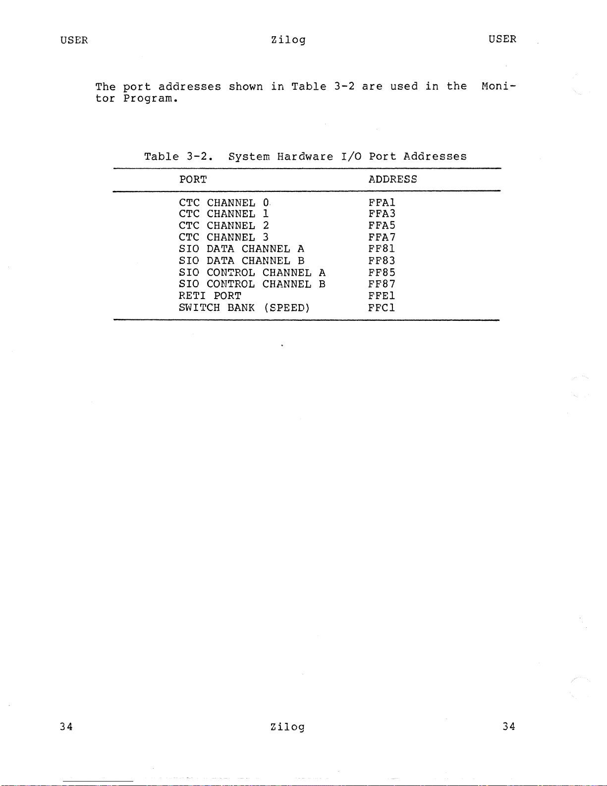
The
port
addresses
shown
in
Table
3-2
are
used
in
the
Moni-
tor
Program.
Table
3-2.
System
Hardware
I/O
Port
Addresses
PORT
ADDRESS
CTC
CHANNEL
O.
FFAI
CTC
CHANNEL
1
FFA3
CTC
CHANNEL
2
FFA5
CTC
CHANNEL
3
FFA7
SIO
DATA
CHANNEL
A
FF8l
SIO
DATA
CHANNEL
B FF83
SIO
CONTROL
CHANNEL
A
FF85
SIO
CONTROL
CHANNEL
B FF87
RETI
PORT
FFEI
SWITCH
BANK
(SPEED)
FFCI
Zilog
34
Page 45

USER
(
35
Zilog
USER
SECTION
4
MONITOR
I/O
PROCEDURES
4.1
Introduction
The
I/O
procedures
most
frequently
used
in
the
Monitor
Pro-
gram
are
given
in
this
section.
These
procedures
are
accessed
by
system
calls
in
user
programs
to
perform
console
I/O
functions.
4.2
I/O
Procedures
TYIN
Description
Gets
a
character
from
the
keyboard
buffer.
If
the
buffer
is
empty,
this
procedure
waits
for
a
character
to
appear.
The
character
is
stored
in
register
RLO,
and
the
contents
of
register
RHO
are
lost.
Example
CONSTANT
TYIN
:=
%04
SC
#TYIN
(character
in
RLO)
TYWR
Description
Displays
the
character
in
RLO.
The
character
is
not
dis~layed
if
the
XOFF
character
has
been
received
before
this
procedure
is
executed.
In
this
case,
the
procedure
waits
until
an
XON
character
is
received
from
the
console
before
displaying
the
character
in
RLO.
If
the
character
to
be
displayed
is
a
carriage
return,
the
zero
flag
is
set,
and
RHO
is
lost.
Zilog
35
Page 46

USER
36
Example
CONSTANT
TYWR
:=
%06
•
SC
#TYWR
(character
in
RLO)
PUTMSG
Description
Zilog
USER
Sends a character
string
to
the
terminal.
Register
R2
con-
tains
the
address
of
the
character
string
buffer,
and
the
first
byte
in
the
buffer
contains
the
number
of
characters
to
be
displayed.
If
there
is
no
return
in
the
string,
the
entire
specified
string
is
displayed.
Otherwise,
the
string
is
displayed
up
to
and
including
the
first
return.
Register
contents
RO,
RI,
and
R2
are
lost.
Example
CONSTANT
PUTHSG:=
%OC
TTY
(string
address
in
R2)
SC
#PUTl-ISG
Description
Receives
and
echoes
at
the
terminal
a
character
string
up
to
the
first
return.
The
character
string
is
stored
in
a
buffer
pointed
to
by
register
R2.
Register
RI
contains
the
size
of
the
buffer.
If
the
size
of
the
character
string
exceeds
the
size
of
the
buffer,
the
zero
flag
is
set.
All
lowercase
alpha
characters
are
converted
to
uppercase
char-
acters
before
they
are
stored
in
the
buffer.
RI
returns
the
actual
number
of
characters
received
from
the
terminal.
The
contents
of
registers
RO
and
R2
are
lost.
Example
CONSTANT
TTY
:=
%08
SC
#TTY
(string
address
in
R2,
size
in
Rl)
Zilog
36
Page 47

USER
37
Zilog
USER
CRLF
Description
Outputs
a
return
followed
by
a
line
feed
to
the
terminal.
The
contents
of
register
no
are
lost.
Example
CONSTAN'!'
CRLF
:=
%OA
SC
#CRLF
Zilog
37
Page 48

USER
Zilog
USER
38
Zilog
38
Page 49

B.'.1
(J
\
USER
39
Zilog
USER
APPENDIX
A
GLOSSARY
The
most
important
terms . and
acronyms
introduced
in
this
manual
are
listed
in
this
Appendix.
address
A
number
that
specifies
one
particular
element
in
a
set
of
similar
elements.
May
be
either
a memory
address
or
an
~/Q
address.
(See
also
segmented
address,
logical
address,
physical
address.)
address
space
A
set
of
addresses.
The Z8000
can
access
eight
separate
address
spaces:
normal-mode
program
memory
space,
system-mode
program
memory
space,
normal-mode
data
memory
space,
system-
mode
data
memory
space,
normal-mode
stack
memory
space,
system-mode
memory
space,
standard
I/O
space,
and
special
I/O
space.
addressing
mode
The way
in
which
the
address
of
an
operand
is
specified.
There
are
eisht
addressing
modes:
Register,
Immediate,
Indirect
Register,
Direct
Address,
Index,
Base
Address,
Relative
Address,
and
Base
Index.
autodecrement
The
contents
of
a
register
are
decre-
mented
and
then
used,
as
specified,
by
the
instruction.
autoincrement
The
contents
of
a
register
are
used,
as
specified,
by
the
instruction
and
then
incremented.
Base
Address
(BA)
addressing
mode
A
based
address
consists
of
a
register
that
contains
the
base
and a 16-bit
~
placement.
The
displacement
is
added
to
the
base
and
the
resulting
address
indi-
cates
the
effective
address.
In
nonseg-
mented
mode,
the
base
address
is
held
in
a
~
register
and
the
displacement
is
in
the
instruction.
In
segmented
mode,
Zilog
39
Page 50

USER
40
Zilog
USER
the
segmented
base
address
is
held
in
a
register
pair
and
the
displacement
is
in
the
instruction.
Base
Index
(BX)
addressing
mode
Based
Indexed
addressing
is
similar
to
Based
addressing
except
that
the
dis-
placement
(index),
as
well
as
the
base,
is
held
in
a
register.
In
nonsegmented
mode,
the
base
address
is
held
in
a word
register
and
the
index
is
held
in
a word
register.
In
segmented
mode,
the
seg-
mented
base
address
is
held
in
a
regis-
ter
pair
and
the
index
is
held
in
a word
register.
BCD
digit
A
Binary
Coded
Decimal
digit
is
encoded
of
the
ten
decimal
digits
into
a
4-bit
code
that
is
simply
the
first
ten
binary
numbers
in
the
binary
number
system
(starting
with
0).
This
code
is
used
to
represent
and
process
numbers
in
the
base-IO
(decimal)
format.
break
The
break
is
a
built-in
command
used
to
exit
from
loops
within
the
control
structure
of
the
shell.
(See
shell.)
breakpoint
A command
that
interrupts
or
stops
pro-
gram
execution
at
a
specified
address
in
the
program.
The
address
specified
in
the
breakpoint
is
the
address
of
the
instruction.
byte
A
byte
is
eight
contiguous
bits;
a
byte
in
memory
starts
on
an
addressable
byte
boundary.
byte
register
An
8-bit
register.
The Z8000
CPU
con-
tains
16
general-purpose
byte
registers,
designated
RLn
and
RHn
(n =
0-7).
code
The
characters
of
an
originating
or
source
language,
each
correlated
with
its
equivalent
expression
in
an
inter-
mediate
or
target
language,
for
example,
alphanumeric
characters
correlated
with
their
equivalent
6-bit
expressions
in
a
binary
machine
language.
Zilog
40
j
Page 51

USER
(
41
command
Zilog
USER
A
function
performed
by
the
system,
either
by
the
shell
or
by a program
residing
in
a
file
in
the
ZEUS
system.
context
switching
CONTROL
Interrupting
the
activity
in.
progress
and
switching
to
another
activity.
A
context
switch
involves
saving
for
later
restoration
the
contents
of
the
general-purpose
registers,
~he
Program
Counter
and
the
~
gng
Status
~.
The
CONTROL
key,
labeled
CTRL,
generates
and
sends
control
instructions
to
the
terminal
during
command
execution.
Any
character
typed
with
the
CTRL
key
pressed
is
transparent
to
the
user,
but
is
recognized
by
the
CPU.
CPU
(central
processing
unit)
The
unit
of
a
computing
system
that
includes
the
circuits
controlling
the
interpretation
of
instructions
and
their
execution.
data
structure
A
logical
organization
of
primitive
ele-
ments
(e.g
byte
or
word)
whose
format
and
access
conventions
are
well
defined.
Examples
of
data
structures
are
tables,
lists,
and
arrays.
data
type
The way
in
which
bits
are
grouped
and
interpreted.
For
an
instruction,
the
data
type
of
an
operand
determines
its
size
and
the
significance
of
its
bits.
Operand
data
types
include
byte,
word,
long
word,
byte
string,
word
string,
and
BCD
digit.
debugging
Debugging
is
the
process
of
correcting
mistakes
in
programs
and
shell
scripts.
The
shell
has
several
options
and
vari-
ables
that
can
be
used
to
aid
in
shell
debugging.
Zilog
41
Page 52

USER
42
diagnostic
Zilog
USER
An
error
message
produced
by a
program
is
often
referred
to
as a diagnostic.
Most
error
messages
are
not
written
to
the
standard
output,
since
that
is
often
directed
away
from
the
terminal.
Instead,
error
messages
are
written
to
the
diagnostic
output,
which
usually
appears
on
the
terminal.
Direct
Address
(DA)
addressing
mode
directory
disk
displacement
DMA
In
this
mode,
the
operand
address
is
contained
within
the
instruction.
A
structure
that
contains
files
is
called
a
directory.
The
directory
in
which
the
user
first
logs
in
is
the
~
directory.
A
flat
circular
plate
with
a
magnetic
surface
on
which
data
can
be
stored
by
selective
polarization
of
portions
of
the
flat
surface.
A number
contained
in
the
instruction
for
use
in
calculating
the
effective
address
of
an
operand.
The
displacement
is
added
to
the
contents
of
a
register
during
the
calculation.
Direct
Memory
Address
is
a
method
for
transferring
data
to
or
from main memory
at
high
speed
by
avoiding
the
CPU
regis-
ters.
effective
address
The
address
obtained
after
indirect
or
indexing
modification.
In
non-segmented
mode,
the
effective
address
is
a
16-bit
number.
In
segmented
mode,
the
effec-
tive
address
consists
of a 7-bit
segment
number
and
16-bit
offset.
In
systems
with
memory
management,
the
effective
address
is
the
logical
address
which
must
be
translated
to
obtain
the
physi-
cal
memory
address.
.
Zilog
42
\.
Page 53

USER
43
EOF
file
name
Zilog
USER
An
~-Qf-~
is
generated
whenever
a
90mmand
reads
to
the
end
of a file
that
it
has
been
given
as
input.
It
can
also
be
generated
at
the
terminal
with
a
control-~.
Commands
rece1v1ng
input
from
a
~
receive
an
end-of-file
\vhen
the
command
sending
them
input
com-
pletes.
Most commands
terminate
when
they
receive
an
end-of-file.
The
shell
has
an
option
to
ignore
end-of-file
from
a
terminal
input,
which
makes
it
possi-
ble
to
avoid
logging
out
accidentally
by
typing
too
many
control-d's.
Each
file
in
ZEUS
has
a name
consisting
of
up
to
14
characters,
not
including
the
slash
character
(I),
which
is
used
in
path
name
building.
Most
file
names
do
not
begin
with
the
pericd
character.
They
contain
only
letters
and
digits,
with
perhaps
a
pericd
separating
the
root
portion
of
the
file
'name
from
an
extension.
horne
directory
Each
user
has
a
horne
directory,'
which
is
given
in
the
password
file
1~/passwd.
The
user
is
placed
in
the
horne
directory
when
first
logging
in.
The
~
or
chdir
command
with
no
arguments
returns
the
user
to
this
directory.
The name
of
this
directory
is
recorded
in
the
shell
variable
~.
Immediate
(I)
addressing
mode
In
this
mode,
the
operand
is
contained
within
the
instruction.
Index
(X)
addressing
mode
In
this
mode,
the
operand
address
is
obtained
by
adding
the
contents
of
an
index'
register
to
a
base
address
con-
tained
in
the
instruction.
index
register
A
word
register
used
to
contain
a
dis-
placement
for
use
in
effective
address
calculation.
Zilog
43
Page 54

USER
44
Zilog
USER
Indirect
Register
(IR)
addressing
mode
input
interrupt
In
this
mode,
the
operand
address
is
contained
within
a
register.
Information
taken
from
the
terminal
or
from
files
is
called
input.
Commands
normally
read
input
from
their
standard
input
which
is,
by
default,
the
termi-
nal.
The
metacharacter
followed
by a
file
name
can
be
used
to
cause
input
to
be
read
from a file.
Many
commands
also
read
.from
a
file
specified
as
argument.
Commands
placed
in
pipelines
are
read
from
the
output
of
the
previous
command
in
the
pipeline.
The
leftmost
command
in
a
pipeline
reads
from
the
terminal
if
its
input
is
not
redirected
and
if
a
file
name
is
not
given
to
use
as
stan-
dard
input.
(See
pipeline.)
An
interrupt
is
a
signal
that
causes
most
programs
to
stop
execution.
It
is
generated
by
pressing
the
RUB
key.
Cer-
tain
programs
such
as C shell
and
the
editors
handle
an
interrupt
in
special
ways,
usually
by
stopping
what
they
are
doing
and
prompting
for
another
command.
interrupt
request
An
event
other
than
a
trap
or
jump
or
call
instruction
that
changes
the
normal
flow
of
instruction
execution.
(See
nonmaskable
interrupts.)
interrupt
service
routine
The
routine
executed
in
response
to
an
interrupt.
interrupt/trap
acknowledge
transaction
The
transaction
initiated
by
the
CPU
in
response
to
an
interrupt
or
trap.
Obtains
an
identifier
word
from
the
interrupting
device
or
memory management
hardware.
Zilog
44
Page 55

USER
I
~~
45
I/O
address
Zilog
USER
The
address
of
an
I/O
port,
always
16
bits
long.
Word
por~s
may
have
even
or
odd
addresses,
Special
I/O
byte
ports
are
even,
and
Standard
I/O
byte
ports
are
odd.
I/O
transaction
Kernel
A
transaction
that
transfers
data
to
or
from
a
peripheral
device
or
memory
management
hardware.
The
system
software
task
-that
manages
task
scheduling
and
intercommunication
for
the
Zilog
S8000
system.
The
Kernel
provides
process
management,
file
management,
and
input/output
(I/O)
pro-
cessing.
logical
address
.login
logout
•
logout
long
word
The
address
manipulated
by
the
program-
mer;
used
by
instructions
and
output
by
the
Z8001.
The
file
.login
in
the
user's
~
directory
1S
read
by
the
C
shell
each
time
the
user
logs
in
to
ZEUS;
the
com-
mands
there
are
executed.
The
logout
command
causes
a
login
shell
to
exit.
Normally,
a
login
shell
exits
when
control-d
is
pressed,
generating
an
end-of-file
(EOF) •
When
a
user
logs
off
of
ZEUS,
the
shell
prints
.logout
and
executes
commands
from
the
file
.logout
in
the
user's
~
directory.
A
long
word
is
32
contiguous
bits;
a
long
word
in
memory
starts
on
an
even
addressable
byte
boundary~
memory
address
An
address
specifying
a
location
in
memory.
Word
and
long-word
addresses
must
be
even,
byte
addresses
may
be
even
or
odd.
Zilog
45
Page 56

USER
46
Zilog
USER
memory management
The
process
of
translating
logical
addresses
into
physical
address
plus
certain
protection
functions.
memory
transactions
Monitor
normal
mode
A
transaction
that
transfers
data
to
or
from
main memory.
The
S8000~Monitor
sets
software
break-
points
for
program
debugging;
includes
I/O
control,
interface
software
for
use
with
a
serial
interface
to
a
remote
com-
puter
system,
and
the
primary
bootstrapper
used
to
bring
the
system
up.
A
running-state
mode
where
the
SiN
flag
in
the
FCW
is
0
and
the
N/S
line
is
High.
In
this
mode,
the
CPU
may
not
execute
privileged
instructions.
non-rnaskable
interrupts
Interrupts
which
cannot
be
disabled.
nonsegmented
mode
A
Running-state
mode
of
the
Z8001
CPU.
In
this
mode,
all
addresses
are
gen-
erated
with
the
same
segment
number.
non-vectored
interrupts
operand
output
Interrupts
which
do no
use
the
identif-
ier
word
as
a
vector
to
an
interrupt
service
routine.
An
item
of
data
operated
on by
an
instruction.
Many
commands
in
ZEUS
produce
data
that
is
called
output.
This
output
is
usu-
ally
placed
on
what
is
known
as
the
standard
output,
which
is
normally
con-
nected
to
the
user's
terminal.
The
shell
has a syntax
using
the
rnetacharac-
ter
>
for
redirecting
the
standard
out-
put
of
a command
to a file.
Using
the
~
mechanism
and
the
rnetacharacter
I,
Zilog
46
/
Page 57

USER
/
(
47
path
name
Zilog
USER
it
is
also
possible
for
the
standard
output
of
one
command
to
become
the
standard
input
of
another
command. Some
commands do
not
direct
their
output
to
the
standard
output,
the
line
printer
command
(~),
for
example,
diverts
its
output
to
the
line
printer.
The
write
command
places
its
output
on
another
user's
terminal.
Commands
also
have
a
diagnostic
output
where
they
write
their
error
messages.
Normally,
these
go
to
the
terminal
even
if
the
standard
output
has
been
sent
to
a
file
or
another
com-
mand,
but
it
is
possible
to
direct
error
diagnostics
along
with
standard
output
using
a
special
mentanotation.
A
list
of
names,
separated
by
a
slash
(/)
characters
forms
a
~~.
Each
component
between
successive
/
charac-
ters
names a
directory
in
which
the
next
component
file
resides.
Path
names
that
begin
with
the
character
/
are
inter-
preted
relative
to
the
LQQt
directory
in
the
file
system.
Other
path
names
are
interpreted
relative
to
the
current
directory
as
reported
by~.
The
last
component
of
a
path
name
can
name a
directory;
however,
it
usually
names a
file.
physical
address
pipeline
The
address
required
for
accessing
the
memory,
obtained
from
the
logical
address
generated
by
the
Z800l
by
memory
management
hardware,
for
example,
the
Z80l0
Memory Management
Unit.
A
group
of
commands
that
are
connected
together
with
the
standard
output
of
each
connected
to
the
standard
input
of
the
next
is
called
a
pipeline.
The
~
mechanism
used
to
connect
these
commands
is
indicated
by
the
vertical
bar
(I)
metacharacter.
Zilog
47
Page 58

USER
48
Zilog
USER
privileged
instruction
program
An
instruction
intended
for
use
pri-
marily
by
an
operating
system,
which
can
be
executed
only
in
system
mode.
In
general,
instructions
that
change
the
processor
state
or
perform
I/O
are
privileged.
A
program
(usually
synonymous
with
~
mana)
is
a
binary
file
that
performs
a
useful
function.
Program
Counter
(PC)
One
of
the
two
Program
Status
registers.
Contains
the
address
of
the
current
instruction
word.
Program
Status
Area
The
area
in
memory
reserved
for
the
starting
program
status
of
the
interrupt
and
trap
service
routines.
Program
Status
Area
Pointer
The
register
that
contains
the
starting
address
of
the
Program
Status
Area.
Program
Status
registers
prompt
pwd
register
The two
registers
(PC
and
FCW)
that
con-
tain
the
program
status.
Many
programs
print
a
prompt
on
the
ter-
minal
when
they
expect
input.
For
exam-
ple,
the
shell
prompts
for
input
with
a
percent
sign
(%).
The
lllid
command
prints
the
full
path
name
of
the
current
working
directory.
A
storage
location
in
hardware
logic
other
than
the
memory.
Bits
within
a
register
are
numbered
from
0,
with
the
least
significant
being
the
rightmost.
(See
also
byte
register,
word
register,
register
pair,
and
register
quad.)
Zilog
48
Page 59

USER
49
Zilog
USER
Register
(R)
addressing
mode
register
pair
register
quad
In
this
mode,
the
operand
is
in
a
general-purpose
register.
One
of
eight
pairs
of
general-purpose
word
registers,
designated
RRn
(n =
0,
2,4,
•••
,12,14).
One
of
four
groups
of
four
word
regis-
ters,
designated
RQn
(r.
=
0,
4,
8,
12).
Relative
Address
(RA)
addressing
mode
reset
RETURN
In
this
mode,
the
operand
address
is
calculated
by
adding
a
displacement
found
in
the
instruction
to
the
current
PC
value.
An
internal
CPU
operation
that
initial-
izes
the
Program
Status
registers.
It
is
activated
by
the
RESET
line.
The
RETURN
key·on
the
terminal
is
used
to
execute
commands
as
they
are
entered.
RUBOUT
The
RUBOUT
key
generates
an
interrupt
signal
that
is
used
to
stop
programs
or
to
cause
them
to
return
and
prompt
for
more
input.
Running
state
One
of
the
three
CPU
states.
In
this
state,
the
CPU
is
fetching
and
executing
instructions
or
handling
interrupts.
segment
In
a
Z8001,
a
set
of
adjacent
memory
addresses
(up
to
64K)
with
the
same
~
~
number
on
lines
SNO-SN6.
segment
number
A
number
specifying
a memory
segment.
Placed
on
the
SNO-SN6
lines
during
memory
transactions
in
the
Z8001
system.
Part
of
a
segmented
address.
Zilog
49
Page 60
USER
50
Zilog
USER
segmented
address
In
Z800l
CPU's,
a
23-bit
value
consist-
ing
of a 7-bit
segment
number
and a 16-
bit
offset.
segmented
mode One
of
the
Running-state
modes
of
the
Z800l
CPU.
In
this
mode,
the
CPU
gen-
erates
addresses
that
can
have
different
segment
numbers.
shell
A
shell
is
a command
language
inter-
preter.
It
is
possible
for
users
to
write
and
run
their
own
shells,
as
shells
are
no
different
from
any
other
program
in
terms
of
system
response.
stack
A
data
structure
used
for
temporary
storage
or
for
procedure
and
interrupt
serVlce
routine
linkages.
A
stack
uses.
the
last-in,
first-out
concept.
As
items
are
added
to,
or
pushed
onto,
the
stack,
the
stack
pointer
decrements;
as
items
are
removed
from,
or
popped
off,
the
stack,
the
stack
pointer
increments.
stack
pointer
A
general-purpose
register
indicating
the
top
(lowest
address)
of a stack.
status
A command
normally
returns
a
status
when
it
finishes.
By
convention,
a
status
of
zero
indicates
that
the
command
suc-
ceeded.
Commands
can
return
non-zero
status
to
indicate
that
some
abnormal
event
has
occurred.
status
flags
Status
flags
are
set
according
to
the
outcome
of
.
certain
instructions
to
direct
the
subsequent
flow
of
the
pro-
gram
as
necessary.
There
are
six
status
flags:
Carry,
Zero,
Sign,
Parity/Overflow,
Decimal
Adjust
and
Half
Carry.
The
first
four
are
grouped
together
to
determine
the
condition
code,
the
last
two
are
used
in
programs
manipulating
~
digits.
Zilog
50
Page 61

USER
51
system
mode
termination
trap
Zilog
USER
A
Running-state
mode
in
which
the
SiN
flag
in
the
FCW
is
1
and
the
NIS
line
is
Low.
In
this
mode,
the
CPU
may
exercise
privileged
instructions.
When
a command
being
executed
finishes,
it
is
said
to
terminate.
Commands
nor-
mally
terminate
when
they
read
an
end-
of-file
from
their
standard
input.
A
condition
that
occurs
at
the
end
of
ar.
instruction
that
caused
an
illegal
operation.
The
zaooo
traps
are
internal
traps
arising
from
system
call;
unimple-
mented
instruction
and
privileged
instructions
executed
in
normal
mode,
and
an
external
trap,
the
segmentation
trap,
arising
from
memory
access
viola-
tions
in
systems
with
memory
management.
A
t~ap
is
similar
to
an
interrupt
in
that
it
causes
the
executing
program
Status
registers
to
be
saved
on
the
sys-
tem
stack.
Traps
cannot
be
disabled.
vectored
interrupts
Interrupts
which
use
the
identifier
word
as
a
vector
to
_the
interrupt
service
routine.
May
be
disabled.
word
Two
contiguous
bytes
(16
bits)
starting
on
an
even
addressable
byte
boundary.
Bits
are
numbered
from
the
right,
0
through
15.
A word
is
identified
by
the
address
of
the
byte
containing
the
most
significant
bit,
bit
15.
word
register
A
16-bit
register.
working
directory
ZEUS
Any
directory
a
user
is
currently
work-
ing
in
is
called
a
working
directory.
ZEUS
is
the
operating
system
for
the
S8000
system.
Zilog
51
Page 62

Page 63

(
Syltems Publications
".der's
Co_e.1I
Your
feedback
about
this documeDt
helps
WI
uc:ertaiD your Deeds
and
ful1il1
them
ill
the
future. PI
....
take
the
time
to
fill
out
this queatioDaire and
retum
it to
WI.
this information will
be
helpful to
WI
and,
in
time,
to future users of
ZUoq
product..
Y~Nmne:
____________________________________________________________
_
CompmyN~:
________________________________________________________
__
A~:
__________________________________________________________
___
Title
of
this document:
Briefly deecribe application:
Doe. this public:ation
JDMt
your
ueda?
0 Yes 0 No U not, why not?
How
are
you
usiDq this public:ation?
o
AJJ
an
introduction
to
the
subject?
o
AJJ
a
reference
manual?
o
AJJ
an
instructor
or
student?
How
do
you
fiDei
the material?
Technicality
Organization
Completeness
Ezcellent
o
o
o
Good
o
o
o
Poor
o
o
o
What
would
have
improved
the
material?
____________________________________
_
Other
comm8Dis
and
suqqeatiou:
U you found
auy
JDi8takes
in
this document,
please
let
uS
know what
and
where
they
are:
______
_
Page 64

~GGO~
•• O ••••••••••••••••••••••••••••••••••••••••••••••
••••••••••••••••••••••••••••••••••••••••••••••••••••••••
111111
BUSINESS
REPLY
MAIL
FIRST
CLASS
PERMIT
NO.
35
CAMPBELL,
CA.
POSTAGE
WILL
BE
PAID
BY
ADDRESSEE
Zilog
Systems Publications
1315
Dell Avenue
Campbell. Califorma
95008
Attn: Publications Manager
NO
POSTAGE
NECESSARY
IF
MAILED
IN
THE
UNITED
STATES
,o.~noooo
•••••••••••••••••••••••••••••••••••••••••••••
•••••••••••••••••••••••••••••••••••••••••••••••••••••••
o
·
·
·
Page 65

Zilog, Inc. 10460
Bubb Road,
Cupertino
, California 95014 Tele
phone
(408)446-4666 TWX 910 -338-762 1
P
rinted
in USA
 Loading...