

Page 1
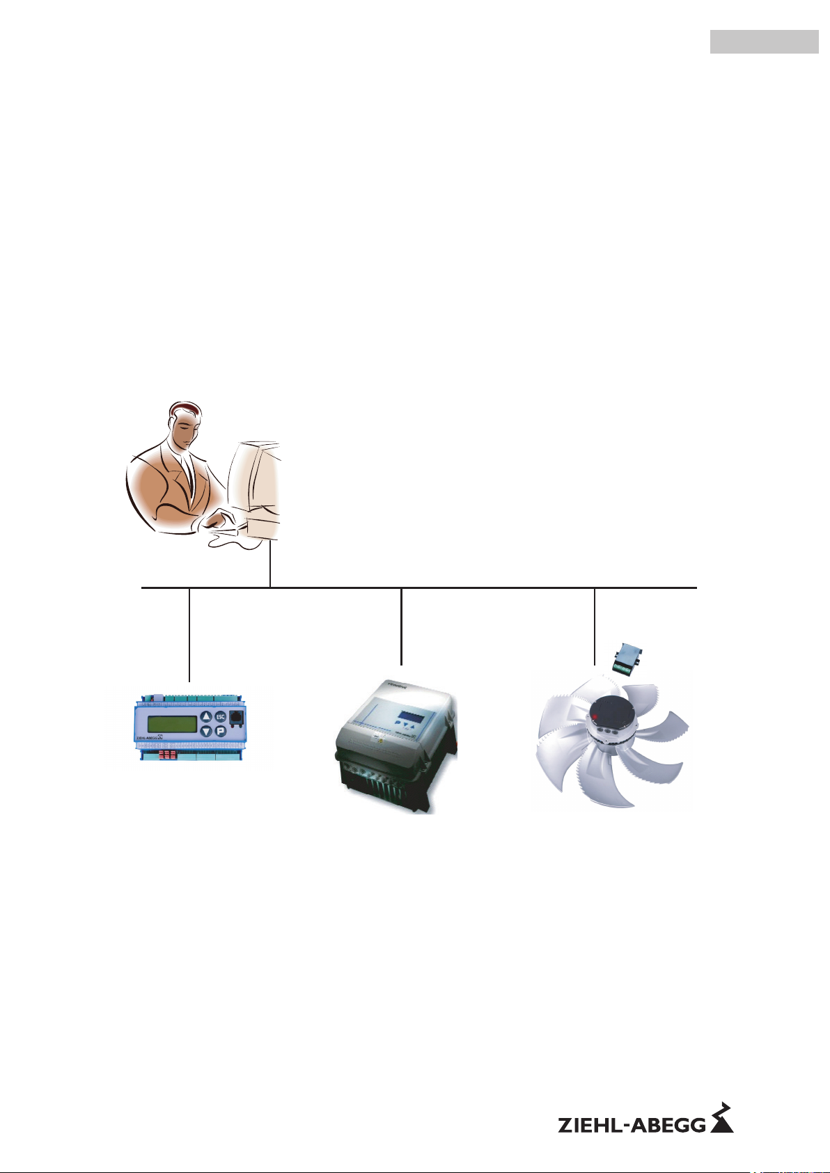
MODBUS RTU System
Technical description and installation
Technical information
MODBUS
COMM Parameter
MB Holding Register Address 3
Access RW, NW
Minimum value 0
Maximum value 65535
Bit [15:8] ……...
.
.
.
R-TIL08_01-GB 1215 Part.-No.
english
Page 2

Content
1 General description . . . . . . . . . . . . . . . . . . . . . . . . . . . . . . . . . . . . . . . . . . . . . . . . . . . . . . . . 3
1.1 Intended use . . . . . . . . . . . . . . . . . . . . . . . . . . . . . . . . . . . . . . . . . . . . . . . . . . . . . . . . 3
1.2 Explanations of symbols . . . . . . . . . . . . . . . . . . . . . . . . . . . . . . . . . . . . . . . . . . . . . . . . 3
2 MODBUS RTU (Remote Terminal Unit) . . . . . . . . . . . . . . . . . . . . . . . . . . . . . . . . . . . . . . . . . 3
2.1 Introduction . . . . . . . . . . . . . . . . . . . . . . . . . . . . . . . . . . . . . . . . . . . . . . . . . . . . . . . . . . 3
3 Hardware installation (Bus topology) . . . . . . . . . . . . . . . . . . . . . . . . . . . . . . . . . . . . . . . . . . 4
3.1 Two-wire MODBUS-topology . . . . . . . . . . . . . . . . . . . . . . . . . . . . . . . . . . . . . . . . . . . . 4
3.2 MODBUS structuring . . . . . . . . . . . . . . . . . . . . . . . . . . . . . . . . . . . . . . . . . . . . . . . . . . 5
4 Physical MODBUS transmission layer . . . . . . . . . . . . . . . . . . . . . . . . . . . . . . . . . . . . . . . . . 6
4.1 Number of devices on a Bus segment . . . . . . . . . . . . . . . . . . . . . . . . . . . . . . . . . . . . . 6
4.2 Cable length . . . . . . . . . . . . . . . . . . . . . . . . . . . . . . . . . . . . . . . . . . . . . . . . . . . . . . . . . 6
4.3 Line termination . . . . . . . . . . . . . . . . . . . . . . . . . . . . . . . . . . . . . . . . . . . . . . . . . . . . . . 7
4.4 Bias of the line . . . . . . . . . . . . . . . . . . . . . . . . . . . . . . . . . . . . . . . . . . . . . . . . . . . . . . . 8
4.5 Pin assignment . . . . . . . . . . . . . . . . . . . . . . . . . . . . . . . . . . . . . . . . . . . . . . . . . . . . . . . 8
4.5.1 RJ45 pin assignment (acc. to MODBUS specification) . . . . . . . . . . . . . . . . . . . . . . 9
4.5.2 Connections 4-pin Phoenix MSTB 2.5 . . . . . . . . . . . . . . . . . . . . . . . . . . . . . . . . . 9
4.5.3 Shielding . . . . . . . . . . . . . . . . . . . . . . . . . . . . . . . . . . . . . . . . . . . . . . . . . . . . . 10
5 MODBUS transmission layer . . . . . . . . . . . . . . . . . . . . . . . . . . . . . . . . . . . . . . . . . . . . . . . . . 10
5.1 Introduction . . . . . . . . . . . . . . . . . . . . . . . . . . . . . . . . . . . . . . . . . . . . . . . . . . . . . . . . . . 10
5.2 Communication parameters . . . . . . . . . . . . . . . . . . . . . . . . . . . . . . . . . . . . . . . . . . . . . 11
5.2.1 Communication parameters for MODBUS member . . . . . . . . . . . . . . . . . . . . . . . . 11
5.2.2 Setting the slave address . . . . . . . . . . . . . . . . . . . . . . . . . . . . . . . . . . . . . . . . . 12
6 Ziehl-Abegg MODBUS-RTU Description . . . . . . . . . . . . . . . . . . . . . . . . . . . . . . . . . . . . . . . . 13
6.1 Introduction . . . . . . . . . . . . . . . . . . . . . . . . . . . . . . . . . . . . . . . . . . . . . . . . . . . . . . . . . . 13
6.2 Data model and access options . . . . . . . . . . . . . . . . . . . . . . . . . . . . . . . . . . . . . . . . . . 13
6.3 Alternative slave-addressing . . . . . . . . . . . . . . . . . . . . . . . . . . . . . . . . . . . . . . . . . . . . . 13
7 Enclosure . . . . . . . . . . . . . . . . . . . . . . . . . . . . . . . . . . . . . . . . . . . . . . . . . . . . . . . . . . . . . . . . 15
7.1 Examples for Bus signals (oscilloscope measurements) . . . . . . . . . . . . . . . . . . . . . . . 15
7.2 Problem solutions . . . . . . . . . . . . . . . . . . . . . . . . . . . . . . . . . . . . . . . . . . . . . . . . . . . . . 15
7.3 Manufacturer reference . . . . . . . . . . . . . . . . . . . . . . . . . . . . . . . . . . . . . . . . . . . . . . . . 16
7.4 Service information . . . . . . . . . . . . . . . . . . . . . . . . . . . . . . . . . . . . . . . . . . . . . . . . . . . . 16
Technical information MODBUS RTU System – model series
R-TIL08_01-GB 1215 Part.-No.
2/16
Page 3
1 General description
1.1 Intended use
This technical information is only complete together with the corresponding operating instructions of the connected components. Therefore the safety information in the operating instructions of the connected components must also be observed.
1.2 Explanations of symbols
Safety instructions are highlighted with warning triangles and are depicted according to the degree of
hazard as follows.
Attention!
General hazardous area. Death or severe injury or significant property damage can occur if the
corresponding precautions are not taken!
Information
Important additional information and advice for user.
2 MODBUS RTU (Remote Terminal Unit)
2.1 Introduction
MODBUS RTU is an international, open field bus standard. MODBUS is used successfully world-wide
as an easy to implement field bus protocol.
The area of application includes production, process and building automation. MODBUS distinguishes
between master and slave devices.
Master devices determine the data transfer on the bus. A master can send messages without an
external request.
Slave devices are peripheral devices. Typical slave devices are input-output devices, valves, drives
and transducers. They receive no bus access authorisation, i.e. they may only acknowledge received
messages or send messages to the master when it requests them to.
In general:
•
Only one master may be active on a bus branch (monomaster bus system)
•
Up to 247 slaves can be addressed on a bus branch
•
Communication always comes from the master; the slaves must respond to requests from the
master
•
Protection function: Checksum and parity bit
Network addressing is performed, unless specified otherwise, by the master in the address range
from 1 to 247, whereby 0 may not be used and address 247 indicates the address preset by the
manufacturer (
chapter 3.4.2.2)
Information
Every member on the bus is addressed by its bus address (field devices address). This address may
only exist once per bus (channel). The slave addresses must always be set to ensure that the bus
master can access the slaves connected to the bus line.
Technical information MODBUS RTU System – model series General description
R-TIL08_01-GB 1215 Part.-No.
3/16
Page 4
MODBUS has no automatic communication parameter adaptation either, i.e. the setting of the control
technology parameters (master) must match the communication parameters of the field devices
(slave).
The master can communicate in two ways with the field devices (slaves):
•
Unicast mode – direct request to a certain field device (slave address not equal to "0"): "Regular"
operation: Master sends request to a field device to which it must reply.
•
Broadcast mode – general request to all field devices (slave address "0"): The master sends a
request (telegram) to all bus members – for example to issue an emergency command to which
none of the field devices may reply.
NETcon MB/TCP
Gateway
150 Ohm
Max 63 FFU
499
150
499
A
B
+
-
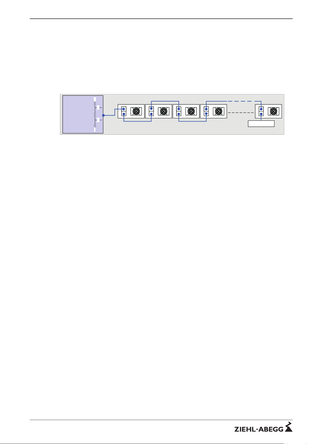
Picture 1: Structure of a channel
A node can show the following modules:
- Control device, Speed controller or Motor-Controller (Fan)
- Passive – Repeater (without intelligence)
The network channels can be connected by a passive Repeater
- Main channel (between control unit and passive repeaters with max. 63 fans)
- End channel (at the output of a passive repeater with max. 63 fans)
Attention: If the "Ziehl-Abegg-Auto-addressing" is to be used, no repeater may be used because the
repeaters cannot pass on the auto-addressing.
A special RS485 transceiver with 1/4 (1/8) UL (Unit Load) and a transfer rate of 19.2 kBd for
connecting up to 63 nodes is used to transfer the information. The cables must be laid in twisted wire
pairs (TP). The correct polarity of these lines is very important.
3 Hardware installation (Bus topology)
3.1 Two-wire MODBUS-topology
The structure of a MODBUS system is a pure bus system (daisy chain). Stub lines up to 30 cm are
permissible but should be avoided.
The implementation of the MODBUS solution by serial lines is based on an electrical "two-wire"
interface (2W - MODBUS) on the basis of the EIA/TIA-RS485 standard with master slave configuration.
All the relevant information such as input and output data, parameters and diagnostic data for the field
devices can be transmitted on just two wires.
Technical information MODBUS RTU System – model series Hardware installation (Bus topology)
R-TIL08_01-GB 1215 Part.-No.
4/16
Page 5
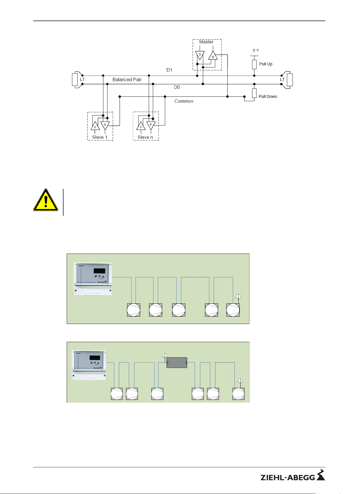
Picture 3: General two-wire topology
In addition to the two signal wires, the MODBUS line can have two other wires for the 24V supply. This
voltage is always required to supply the terminals of the "AXG" type series. The voltage can be fed in
by the first slave for example.
Attention
Wrong polarity of the supply voltage or switching of the bus wires with the supply voltage wires can
destroy the interfaces. If an RS232/RS485 converter (gateway) is used, this must be electrically
isolated.
3.2 MODBUS structuring
The following pictures show examples of an unsegmented (picture 4) and a segmented (picture 5) bus
structure.
Master
RT + Fail Safe
integrated
Bus 1
1 2 3 62
63
RT
150
Picture 4: One segment with MODBUS master
Bus 1
1
2
63
1 2 63
Bus 1: RT deactivated
Bus 2: RT activated
Bus 2
RT
150
Active
Repeater
RT
150
Master
RT + Fail Safe
integrated
Picture 5: Two segments connected to a repeater
Technical information MODBUS RTU System – model series Hardware installation (Bus topology)
R-TIL08_01-GB 1215 Part.-No.
5/16
Page 6
4 Physical MODBUS transmission layer
4.1 Number of devices on a Bus segment
One channel, unless otherwise specified, max. consist of 63 active nodes
•
MODBUS-master
•
MODBUS-slave
•
Repeater
A passive repeater must be used if more than 63 nodes have to be connected to a network.
Repeaters serve to connect the bus segments and refresh the data signals. Repeaters also extend
the maximum permissible line length. Using repeaters increases the signal run times. Therefore a
maximum of two repeaters are permitted between two stations.
Information
If an external terminal (e.g. "AXG" or "ZTG8-L") is used, the voltage must be supplied before a
repeater. A supply beyond a repeater is not possible.
4.2 Cable length
Bus line (segment):
The length of the bus line from one end to the other may not exceed a total maximum length of 1,000
m (500 m for CAT5/7). Any existing stub lines must be added to the total line length.
The bus length can be increased by using repeaters (maximum 1 repeater in series).
Information
If an external terminal (e.g. type series "AXG") is used or devices (e.g. ZTG8-L) are supplied with
voltage via the bus, the maximum line length from the device up to its voltage supply must be limited
depending on the used line and the current consumption - min. supply voltage 7 V at 12 V and 10.8 V
at 24 V.
Maximum line length when connecting external consumers:
Voltage supply 12 V 24 V 12 V 24 V
Power consumption 120 mA 50 mA
CAT 5/7 80 m 180 m 200 m 450 m
J-Y (St) 2x2x0,6 250 m 550 m 600 m 1000 m
AWG 22 280 m 600 m 650 m 1000 m
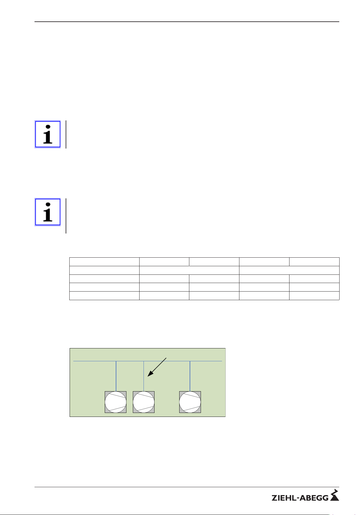
Stubs:
If the supply lines, from the main line to the individual nodes, are designed as stub lines and the
individual stub lines are shorter than 30 cm, a bus topology can still also be referred to in this case.
However, this stub line must be included in the calculation of the total length. However, stub lines
should be avoided if possible.
Bus 1 Stubs / Stichleitungen < 30 cm
2 1 63
Picture 6: Stubs
Technical information MODBUS RTU System – model series Physical MODBUS transmission layer
R-TIL08_01-GB 1215 Part.-No.
6/16
Page 7

Information
The following line types (line impedance typically 100 Ω) are recommended for the line selection:
•
J-Y (St) 2x2x0,6
•
CAT5/7
•
AWG 22
Note
Please make sure that only two twisted wires are used for the network line for lines with more than two
wires. Parallel laying of several wires is not permitted.
OK
not OK
A (D+)
unused
B (D-)
A (D+)
B (D-)
unused
Picture 7: Line connection
The main objective in building the network must be that a smooth traffic is possible in each network
segment.
Information
Pay attention to sufficient distance from power lines and motor wires (min. 20 cm) The bus line should
be laid in a separate, conductive and earthed cable duct.
4.3 Line termination
Line terminations should be used to ensure trouble-free data transfer on the lines. The total resistance
of 54 Ω in a network is based on the specifications of EIA/TIA - 485 and should not be dropped below
of.
Terminations may only be fitted to the ends of the bus line. No more than 2 terminations may exist in
lines without repeaters.
The following devices usually contain a connectable termination (and bias resistors)
•
MODBUS-master
•
Repeater
Since the MODBUS slave devices normally have no built-in termination, an external termination (art.
no. 380080) should preferably be connected to the end of the line.
When positioning the terminating resistors following points must be observed:
•
Where are the nodes positioned?
•
Where are the repeaters positioned?
•
where the PC is placed
•
Where is the start and end of the bus?
•
What are the resulting total line lengths?
Attention
When a termination is used, must it always be positioned at the start and end of the bus?
There are different ways to avoid dropping below the specified total resistance of 54 Ω of a
network channel:
1. Insert external resistances (Ziehl-Abegg 150 Ω) on the bus
2. Use internal resistances (Ziehl-Abegg 150 Ω) at the bus connections of the repeaters
3. a combination of internal and external resistors
Technical information MODBUS RTU System – model series Physical MODBUS transmission layer
R-TIL08_01-GB 1215 Part.-No.
7/16
Page 8
Information
The internal terminations of the repeaters are not activated in the factory setting. Those of the display
and operating devices are activated in the factory setting. If a resistance is activated at the input or
output, it is 150 Ω (the data in the operating instructions must always be observed!)
The PC card (RS232/RS485 gateway), EC-Controller, adapter and accessory modules have no
integrated terminating resistances. Chapter 3.2 describes in brief where the terminating resistances
are best positioned.
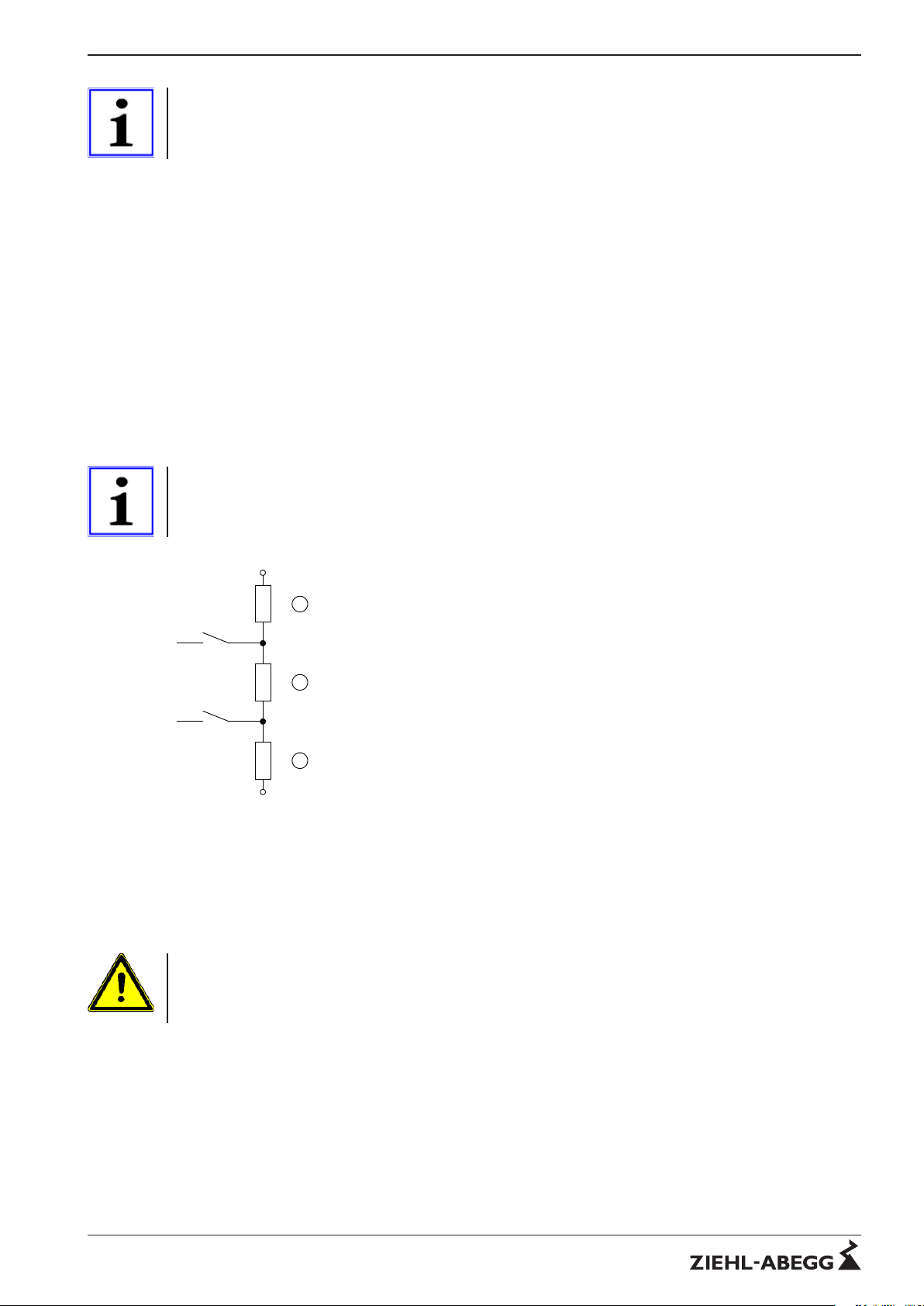
4.4 Bias of the line
All the devices on the bus are in reception mode in the quiescent state of the RS-485 bus. If a
termination is used and the bus has no driving variable, the bus line is in an undefined state. Bias
resistors (failsafe) must be used to then obtain a defined voltage potential on the data lines in the
quiescent state. The bias resistors act for data line "A" (D+) as pull-up resistors (normally against 5 V)
and for data line "B" (D-) as pull-down resistors (against GND).
The following devices usually have built-in bias resistors:
•
MODBUS-master
•
MB/TCP Gateway
•
Repeater
For single devices these must be activated via jumper.
Information
Please see the "RS-485 interface for MODBUS - RTU" section of the individual device instructions!
5 V
Common
(GND)
1
1
2
Picture 8: Example for built-in resistors
1 Bias resistor
2 Line termination
4.5 Pin assignment
Different Ziehl-Abegg designation
D+ corresponds to the connection (A)
D- corresponds to the connection (B)
Technical information MODBUS RTU System – model series Physical MODBUS transmission layer
R-TIL08_01-GB 1215 Part.-No.
8/16
Page 9
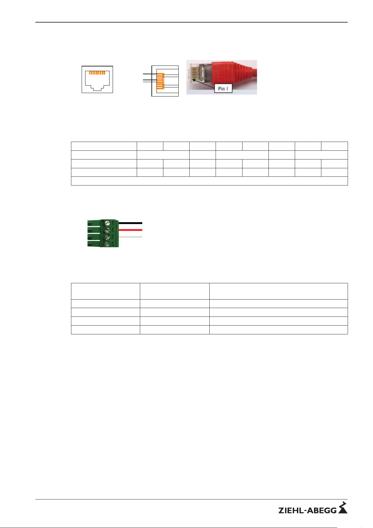
4.5.1 RJ45 pin assignment (acc. to MODBUS specification)
2W - MODBUS and RJ45 connection
1 8
FRONT
1
8
Common
D0
D1
TOP
Picture 9: RJ45 MODBUS assignment
Pair assignment patch cable CAT5/7 RJ45
Pin 1 2 3 4 5 6 7 8
Pair number 3 2 1 2 4
Colour EIA/TIA 568 A WH / GN GN WH / OG BU WH / BU OG WH / BN BR
Colour EIA/TIA 568 B WH / OG OG WH / GN BU WH / BU GN WH / BN BR
Note: Pair 2 on Pin 3 + 6 !
4.5.2 Connections 4-pin Phoenix MSTB 2.5
D-
D+
GND
+24V
Picture 10: Pin assignment
Assignment table
Ziehl-Abegg
Description
MODBUS
Description
Description
D- (D1) D1 (B) V1 voltage, V1 > V0 → 1 [OFF] State
D+ (D0) D0 (A) V0 voltage, V0 > V1 → 0 [ON] State
GND Common optional (circuit ground)
+24 VP optional (24V power supply)
When using telephone flex (J-Y (St) 2x2x0,6), we recommend the following allocation:
"A" (D+) = red
"B" (D-) = black
"GND" = white
"+24V" = yellow
Technical information MODBUS RTU System – model series Physical MODBUS transmission layer
R-TIL08_01-GB 1215 Part.-No.
9/16
Page 10
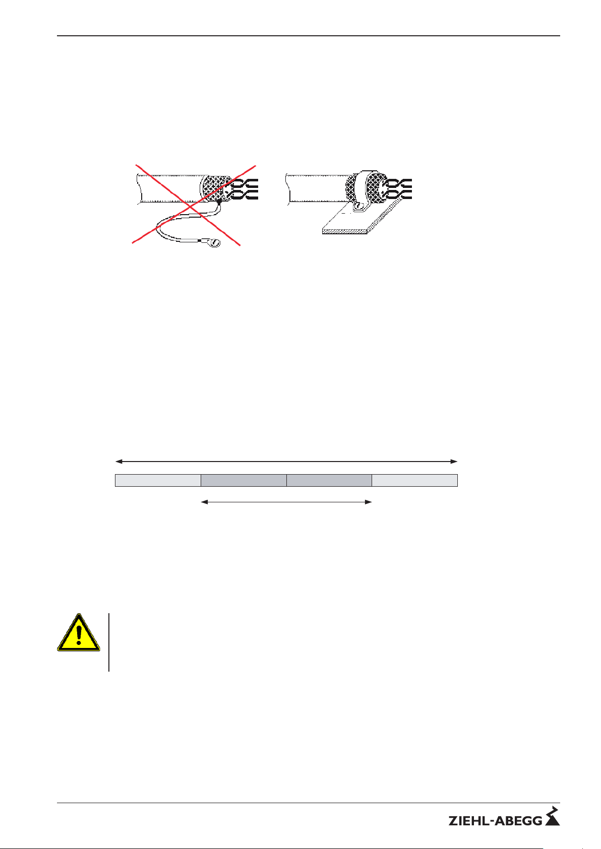
4.5.3 Shielding
The use of shielded cables is normally not demanded but offers high protection against electromagnetic interferences, especially high frequencies. However, the effectiveness of the shield depends
on careful installation of the line.
If shielded cables are used, the shield should be placed at "PE" on at least one side (preferably on the
master connection). The occurrence of compensating currents may have to be considered if the shield
is contacted on both sides.
Picture 11: Shield connection of lines
5 MODBUS transmission layer
5.1 Introduction
MODBUS is a data transfer protocol of the application layer for the master-slave communication
between the devices connected to the network.
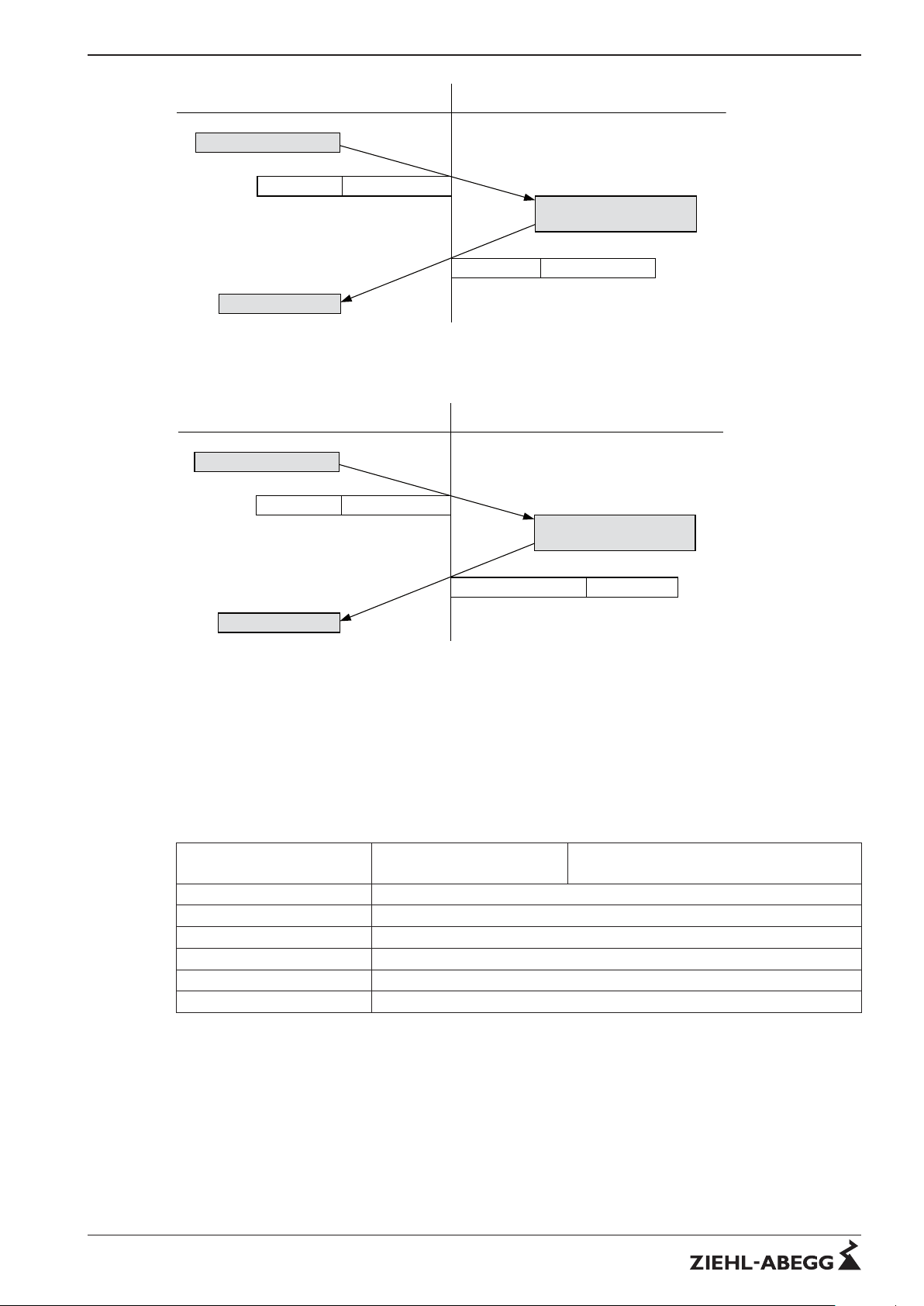
Requests can only be initiated by the master, the reply comes only from the addressed slave. None of
the slaves replies to a broadcast request (request to all slaves).
Structure of the MODBUS frame:
The MODBUS application protocol defines a simple Protocol Data Unit (PDU).
Adressfeld Funktionscode Daten CRC
PDU für serielle MODBUS-Übertragung
MODBUS PDU
Picture 12: General MODBUS frame
The address field only contains the slave address in the serial MODBUS transmission. The CRC
value (Cyclic Redundancy Check) is calculated by the transmitting device and appended to the
message to be sent. The receiving device also calculates a CRC value during reception of the
message and then compares this with the original value received in the CRC field. There is an error if
these two values are not identical.
Attention
It must be ensured that all devices have different addresses otherwise abnormal, unforeseeable states
may occur on the serial bus so that communication of the master with the slaves on the bus is no
longer possible.
The set address is retained voltage failure.
Technical information MODBUS RTU System – model series MODBUS transmission layer
R-TIL08_01-GB 1215 Part.-No.
10/16
Page 11
Initiierung der Anforderung
Master
MODBUS-Transaktion (ohne Fehler)
Slave
Empfang der Antwort
Ausführung der Aktion
Initiierung der Antwort
Funktionscode Anforderungsdaten
Funktionscode Antwortdaten
Initiierung der Anforderung
Master
MODBUS-Transaktion (Antwort mit Fehlermeldung (Exception))
Slave
Empfang der Antwort
Fehlererkennung in Aktion
Initiierung der Fehlerantwort
Funktionscode Anforderungsdaten
Exception Funktionscode Antwortdaten
Picture 13: MODBUS Communication Master - Slave
5.2 Communication parameters
5.2.1 Communication parameters for MODBUS member
Different parameters must be set for the MODBUS communication between the master and the
slaves. These parameters and their settings are listed in the table below:
Address range (unless otherwise noted)
Slave:
1 – 247
Master:
no special address
Broadcast Yes
Transmission rate 19.200 Bd (default)
Parity/Stop Even (standard) or none (CTE, PTE, UTE32)
Mode RTU
Interface RS485 2W – MODBUS
Data 8 data bits
Technical information MODBUS RTU System – model series MODBUS transmission layer
R-TIL08_01-GB 1215 Part.-No.
11/16
Page 12

5.2.2 Setting the slave address
The members are delivered with slave address 247 (unless specified otherwise). The slave addresses
must always be set to ensure that the bus master can access the slaves connected to the bus line.
Information
The setting is made depending on the member directly on it, by its built-in control unit or an externally
connected control unit, e.g. type series "AXG" in the “IO-Setup” menu item.
→ The detailed instructions which can be found in the appropriate operating instructions of the
connected components must also be observed (Attention: partly limited address range)!
However, the address setting is easier when the terminating device has address setting switches or
similar devices for address setting.
The set address is retained voltage failure.
Information
In accordance with the MODBUS standard addresses 1 to 247 can be used. Address 0 is reserved
and may not be used for slaves!
Technical information MODBUS RTU System – model series MODBUS transmission layer
R-TIL08_01-GB 1215 Part.-No.
12/16
Page 13
6 Ziehl-Abegg MODBUS-RTU Description
6.1 Introduction
The Ziehl-Abegg device series are equipped with an RS-485 interface (A [D+], B [D-], GND). The
device can be controlled and parameterised by the MODBUS-RTU protocol by using this interface.
The MODBUS-RTU protocol implementation of the device complies with the standards as described
in the "MODBUS Application Protocol Specification 1.1". Not all the function codes contained therein
are implemented in the device. The device basically supports all functions which are available for
holding and input registers.
6.2 Data model and access options
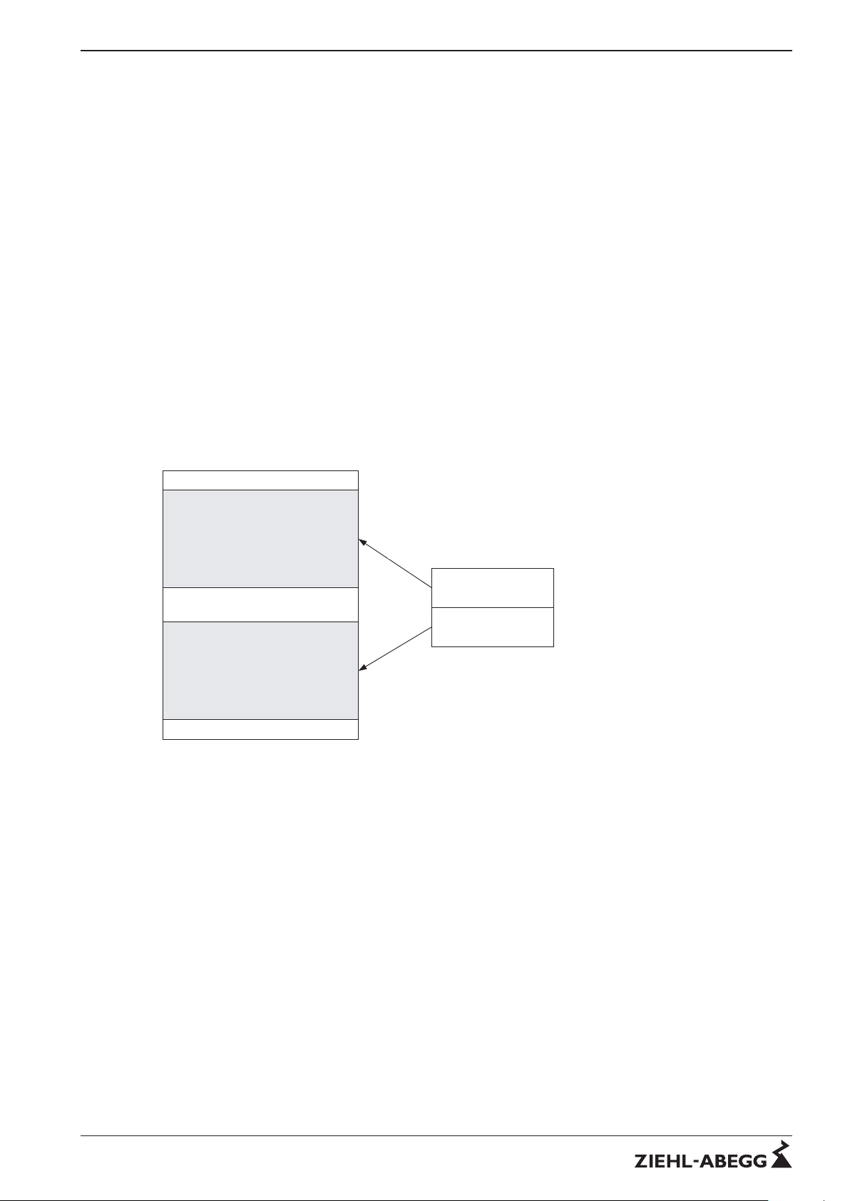
The application data of the device are organised so that access to them is possible with the MODBUS
function for 16-bit registers.
Data items which have a smaller word width internally are extended to 16 bits, data items which have
a larger word width are distributed to 2 registers. The device does not support bit-oriented data items.
The MODBUS access to the application data is gained with the following MODBUS functions for
registers:
•
Read Input register (function code 4)
•
Read Holding register (function code 3)
•
Write Single register (function code 6)
•
Write Multiple registers (function code 16)
Les- und schreibbare Daten
(z.B. Parameter)
Lesbare Daten
(z.B. Istwerte)
Holdings Registers
Input Registers
R/W
R
MODBUS Zugriff
Applikationsdaten
Picture 14: data model
The application data are arranged completely in the Holding Register and the Input Register section
respectively beginning at MODBUS register address 0. An exception message is output on exceeding
the register range.
6.3 Alternative slave-addressing
Addressing is performed by the built-in terminal, an external terminal or a PC with the appropriate
software (e.g. NETcon).
There is a menu item for this in the "IO Setup" menu group. The address is programmed to the highest
possible MODBUS address (247) in the factory setting.
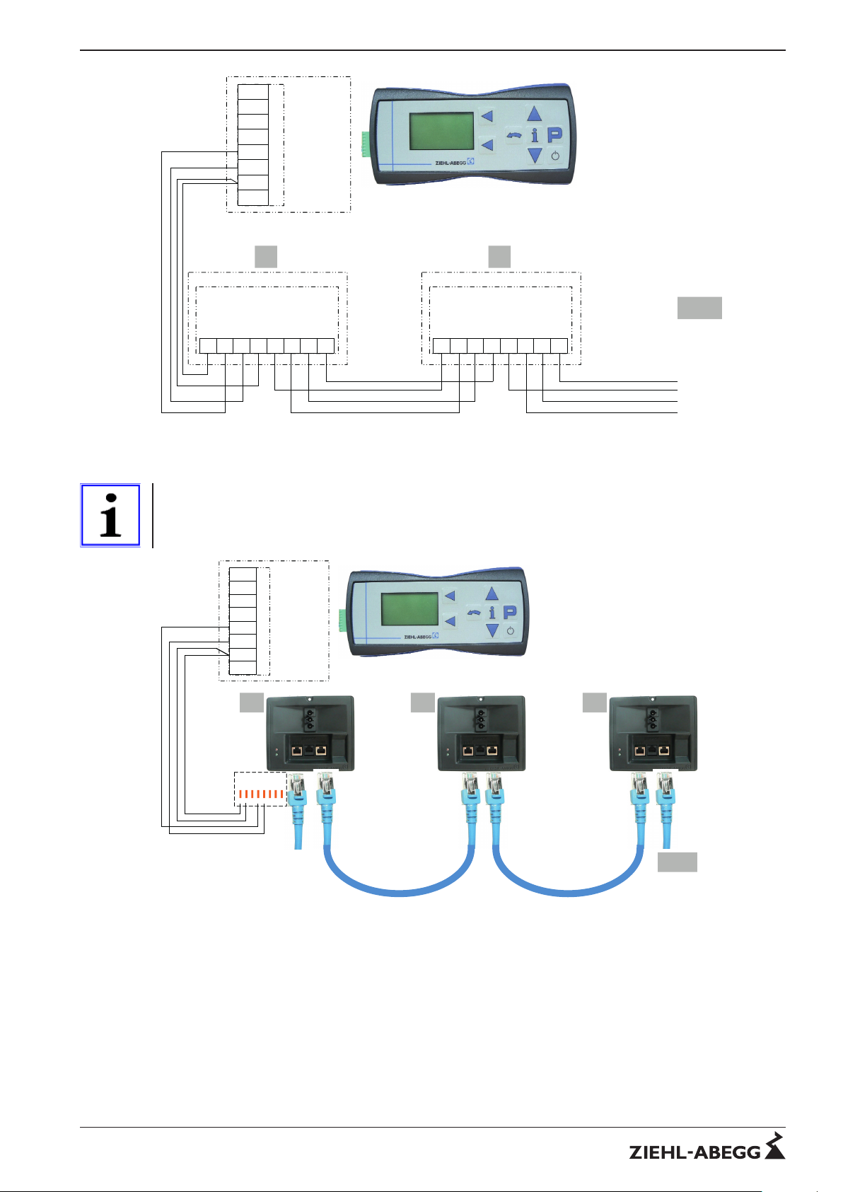
The Ziehl-Abegg ECblue fans with AM-MODBUS modules also offer the possibility of automatic
addressing in the connection with our MB/TCP gateway. The line ID must be connected additionally
for this.
Technical information MODBUS RTU System – model series Ziehl-Abegg MODBUS-RTU Description
R-TIL08_01-GB 1215 Part.-No.
13/16
Page 14
09.03.2011
v_modbus_net_autoadr.vsd
ECblue MODBUS
ID1 GND
A
(D+)B(D-)
ID2GND
A
(D+)B(D-)
B
(D-)
ID1 GND
A
(D+)B(D-)
ID2GND
A
(D+)
A-G-247NW
+ 3,3 V
1 2
IRDA-RXD
IRDA-TXD
IRDA-SD
A
(D+)
B
(D-)
GND
+ 5 V
3...63
ECblue MODBUS
MODBUS
(RS-485)
MODBUS
(RS-485)
Addressing
Addressing
MODBUS
(RS-485)
MODBUS
(RS-485)
Addressing
Addressing
Picture 15: Structure with autoaddressing
Information
Additional information please refer the relevant manuals of the devices
23.02.2011
v_modbus_net_autoadr_cbox.eps.vsd
A-G-247NW
+ 3,3 V
IRDA-RXD
IRDA-TXD
IRDA-SD
A
(D+)
B
(D-)
GND
+ 5 V
4...63
1
BUS1 BUS2
2
BUS1 BUS2
3
BUS1 BUS2
GND
ID1
A (D+)
B (D-)
8 7 6
5
4 3 2 1
RJ45
RJ45 RJ45
Picture 16: Structure with connection box and RJ 45 cabling
Technical information MODBUS RTU System – model series Ziehl-Abegg MODBUS-RTU Description
R-TIL08_01-GB 1215 Part.-No.
14/16
Page 15
7 Enclosure
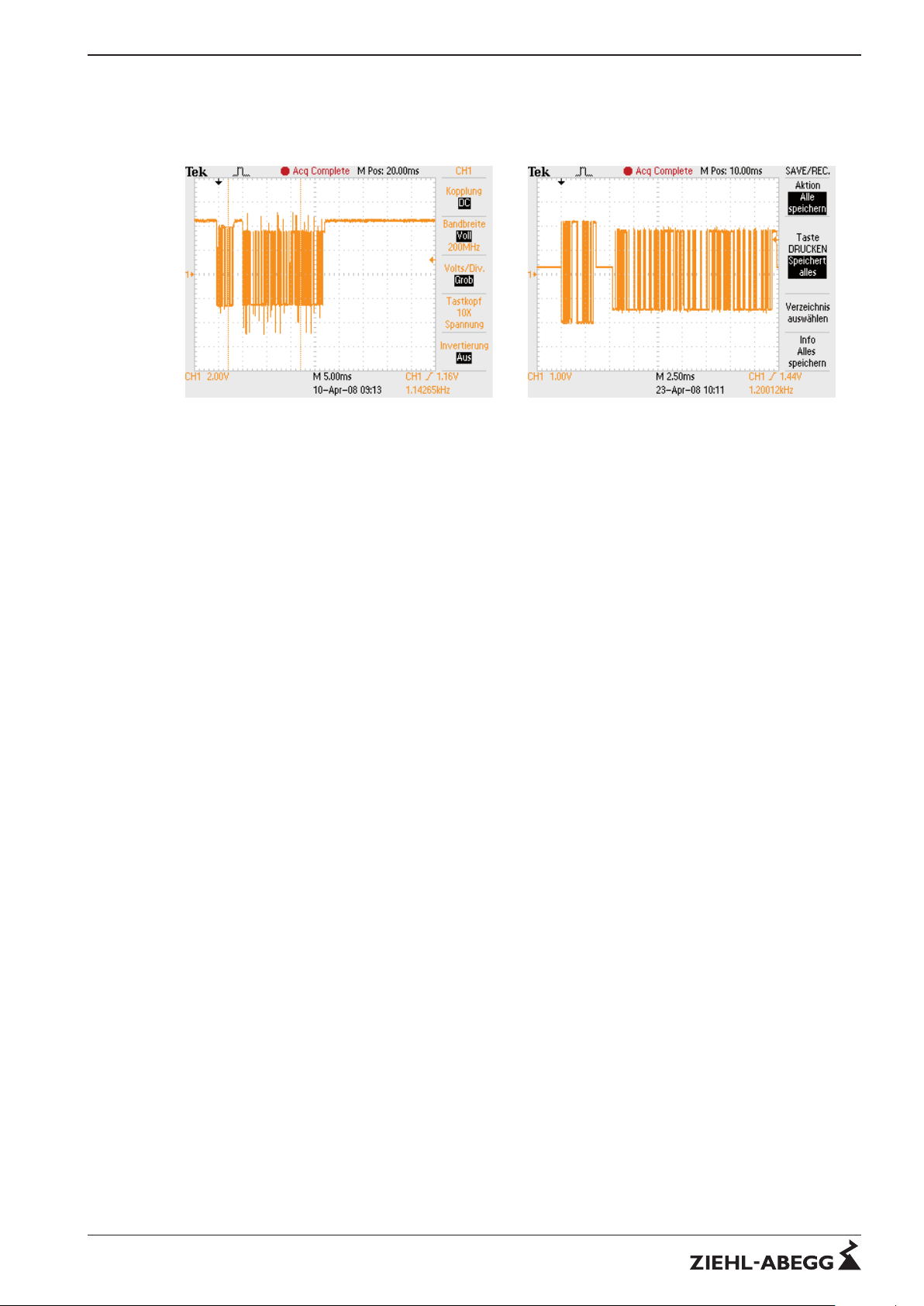
7.1 Examples for Bus signals (oscilloscope measurements)
Request node without RT without FS Request node with RT and FS
RT = Terminations resistance (150 Ω)
FS = Fail safe termination
7.2 Problem solutions
No response, no communication
A termination at both ends is recommended in RS485 networks. Communication problems may occur
if it is missing entirely or partly.
•
The transfer rate of the network interface is set incorrectly.
– Check the termination visually or with an LCR meter
– Check the continuity of the bus line with a line tester and LCR meter
– Test sections to localise the error range
– The transfer rate must be set identically for master and slave
– Slave address may only exist once per channel
•
Too many transmission errors (Transmission Errors, CRC Errors):
– The shield should always be contacted on shielded bus lines. The shield is usually contacted
on "PE"
– In systems with branches over several floors, potential shifts of the PE connections may
occur which cause a compensation current by the shield which can lead to communication
disturbances. To prevent this, the shield can be disconnected if necessary by an unshielded
adapter on one side of the bus line.
•
Interferences from the power electronics: Every power electronics has an integrated EMC line
input filter which requires a low-ohmic, low-inductance "PE" connection to work properly.
– Check "PE" connections in the branch sockets for safe contact.
– If power lines are too long, the fan housings may have to be earthed additionally
Technical information MODBUS RTU System – model series Enclosure
R-TIL08_01-GB 1215 Part.-No.
15/16
Page 16

7.3 Manufacturer reference
Our products are manufactured in accordance with the relevant international regulations. If you have
any questions concerning the use of our products or plan special uses, please contact:
Ziehl-Abegg AG
Heinz-Ziehl-Straße
74653 Künzelsau
Telephone: +49 (0) 7940 16-0
Telefax: +49 (0) 7940 16-504
[email protected]
http://www.ziehl-abegg.de
7.4 Service information
If you have any technical questions while commissioning or regarding malfunctions, please contact
our V-STE support department for control systems - ventilation technology.
Our worldwide contacts are available in our subsidiaries for deliveries outside of Germany.
www.ziehl-abegg.com.
If you make returns for inspections or repairs we need certain information in order to facilitate focused
trouble shooting and fast repair. Please use our repair tickets for this. It is provided to you after you
have consulted our support department.
In addition, you can download it from our homepage. Download - Ventilation Technology - Topic:
Control Engineering - Document type: General documents.
Technical information MODBUS RTU System – model series Enclosure
R-TIL08_01-GB 1215 Part.-No.
16/16
 Loading...