

Page 1

R-TBA13_01-GB 1630 Art.-Nr. 00163414-GB
Brake Module
Brake activation for ZAdyn4C
Original operating instructions
Store for future use !
Page 2

Content
1 General information . . . . . . . . . . . . . . . . . . . . . . . . . . . . . . . . . . . . . . . 4
1.1 Structure of the operating instructions . . . . . . . . . . . . . . . . . . . . 4
1.2 Target group . . . . . . . . . . . . . . . . . . . . . . . . . . . . . . . . . . . . . . . . 4
1.3 Exclusion of liability . . . . . . . . . . . . . . . . . . . . . . . . . . . . . . . . . . 4
1.4 Copyright . . . . . . . . . . . . . . . . . . . . . . . . . . . . . . . . . . . . . . . . . . 4
2 Safety instructions . . . . . . . . . . . . . . . . . . . . . . . . . . . . . . . . . . . . . . . . 5
2.1 General . . . . . . . . . . . . . . . . . . . . . . . . . . . . . . . . . . . . . . . . . . . 5
2.2 Intended use . . . . . . . . . . . . . . . . . . . . . . . . . . . . . . . . . . . . . . . 5
2.3 Pictographs . . . . . . . . . . . . . . . . . . . . . . . . . . . . . . . . . . . . . . . . 5
2.4 Product safety . . . . . . . . . . . . . . . . . . . . . . . . . . . . . . . . . . . . . . 6
2.5 Requirements placed on the personnel / due diligence . . . . . . . 6
2.6 Commissioning . . . . . . . . . . . . . . . . . . . . . . . . . . . . . . . . . . . . . . 6
2.7 Working on device/hazards through residual voltage . . . . . . . . . 7
2.8 Modifications / interventions in the device . . . . . . . . . . . . . . . . . 7
2.9 Operator’s obligation of diligence . . . . . . . . . . . . . . . . . . . . . . . . 7
2.10 Employment of external personnel . . . . . . . . . . . . . . . . . . . . . . . 8
3 Product overview . . . . . . . . . . . . . . . . . . . . . . . . . . . . . . . . . . . . . . . . . 8
3.1 Application . . . . . . . . . . . . . . . . . . . . . . . . . . . . . . . . . . . . . . . . . 8
3.2 Functional description . . . . . . . . . . . . . . . . . . . . . . . . . . . . . . . . . 8
3.3 Service & maintenance . . . . . . . . . . . . . . . . . . . . . . . . . . . . . . . 8
3.4 Transport . . . . . . . . . . . . . . . . . . . . . . . . . . . . . . . . . . . . . . . . . . 8
3.5 Disposal & recycling . . . . . . . . . . . . . . . . . . . . . . . . . . . . . . . . . . 8
4 Mechanical installation . . . . . . . . . . . . . . . . . . . . . . . . . . . . . . . . . . . . 9
4.1 General notes . . . . . . . . . . . . . . . . . . . . . . . . . . . . . . . . . . . . . . . 9
4.2 Assembly on the ZAdyn4C 011-032 . . . . . . . . . . . . . . . . . . . . . . 10
4.3 Assembly on the ZAdyn4C 040-074 . . . . . . . . . . . . . . . . . . . . . . 12
4.4 Dimensions / minimum clearances . . . . . . . . . . . . . . . . . . . . . . . 14
5 Electrical installation . . . . . . . . . . . . . . . . . . . . . . . . . . . . . . . . . . . . . . 16
5.1 EMC-compatible installation . . . . . . . . . . . . . . . . . . . . . . . . . . . . 16
5.2 Terminal positions . . . . . . . . . . . . . . . . . . . . . . . . . . . . . . . . . . . . 17
5.3 Strain relief . . . . . . . . . . . . . . . . . . . . . . . . . . . . . . . . . . . . . . . . . 18
5.4 Protective earth connection . . . . . . . . . . . . . . . . . . . . . . . . . . . . 18
5.5 Connection motor brake . . . . . . . . . . . . . . . . . . . . . . . . . . . . . . . 19
Original operating instructions
Brake Module
R-TBA13_01-GB 1630 Part.-No. 00163414-GB
2
/32
Page 3

5.6 Connection ZAdyn4C . . . . . . . . . . . . . . . . . . . . . . . . . . . . . . . . . 19
5.6.1 Activation of the brake contactor K3. . . . . . . . . . . . . . . . . . 19
5.6.2 Triggering operation without contactors . . . . . . . . . . . . . . . 19
5.7 Connection control system . . . . . . . . . . . . . . . . . . . . . . . . . . . . . 20
5.7.1 Evaluation of the safety circuit . . . . . . . . . . . . . . . . . . . . . 20
5.7.2 Contactor control . . . . . . . . . . . . . . . . . . . . . . . . . . . . . . 20
5.7.3 Motor brake operating voltage . . . . . . . . . . . . . . . . . . . . . 20
5.7.4 Brake test / emergency rescue . . . . . . . . . . . . . . . . . . . . . 20
5.8 Brakes . . . . . . . . . . . . . . . . . . . . . . . . . . . . . . . . . . . . . . . . . . . . 20
5.8.1 Brake contactors . . . . . . . . . . . . . . . . . . . . . . . . . . . . . . 20
5.8.1.1 Brake release monitoring by the ZAdyn4C . . . . 20
5.9 Process . . . . . . . . . . . . . . . . . . . . . . . . . . . . . . . . . . . . . . . . . . . 21
5.10 Circuit suggestions Brake Module and ZAdyn4C . . . . . . . . . . . . 22
5.10.1 Actuation for brakes without over excitation . . . . . . . . . . . . 22
5.10.2 Actuation for brakes with over excitation . . . . . . . . . . . . . . 23
6 Enclosure . . . . . . . . . . . . . . . . . . . . . . . . . . . . . . . . . . . . . . . . . . . . . . . 24
6.1 Technical Data Brake Module . . . . . . . . . . . . . . . . . . . . . . . . . . . 24
6.2 Type designation . . . . . . . . . . . . . . . . . . . . . . . . . . . . . . . . . . . . 25
6.3 Part no. . . . . . . . . . . . . . . . . . . . . . . . . . . . . . . . . . . . . . . . . . . . 26
6.4 EU declaration of conformity . . . . . . . . . . . . . . . . . . . . . . . . . . . 27
Original operating instructions
Brake Module
R-TBA13_01-GB 1630 Part.-No. 00163414-GB
3
/32
Page 4

1 General information
1.1 Structure of the operating instructions
These Operating Instructions serve for safe working on and with the Brake Module for
the ZAdyn4C. It contains safety instructions that must be complied with as well as
information that is required for failure-free operation of the device.
Keep these operating instructions together with the device. It must be ensured that all
persons that are to work on the device can refer to the operating instructions at any time.
In addition to the operating instructions, directives in the sense of the ordinance on
industrial safety and health and the work equipment ordinance are also to be provided.
Keep the operating instructions for continued use. They must be passed-on to all
successive owners, users and final customers.
1.2 Target group
The operating instructions address persons entrusted with planning, installation, commissioning and maintenance and servicing and who have the corresponding qualifications and skills for their job.
1.3 Exclusion of liability
Concurrence between the contents of these operating instructions and the described
hardware and software in the device has been examined.
It is still possible that non-compliances exist; no guarantee is assumed for complete
conformity. The contents of this manual are put through periodic reviews. Necessary
modifications are incorporated into the next version.
ZIEHL-ABEGG SEis not liable for damage due to misuse, incorrect use, improper use or
as a consequence of unauthorized repairs or modifications.
1.4 Copyright
These operating instructions contain copyright protected information. The operating
instructions may be neither completely nor partially photocopied, reproduced, translated
or put on data medium without previous explicit consent from ZIEHL-ABEGG SE.
Infringements are liable for damages.
All rights reserved, including those that arise through patent issue or registration on a
utility model.
Original operating instructions
Brake Module General information
R-TBA13_01-GB 1630 Part.-No. 00163414-GB
4
/32
Page 5

2 Safety instructions
2.1 General
This chapter contains instructions to prevent personal injury and property damage.
These instructions do not lay claim to completeness. In case of questions and problems,
please consult our company technicians.
2.2 Intended use
The Brake Module is an external auxiliary unit to the ZAdyn4C for activating the motor
brakes with contactors. The device is not designed for any other use than those listed
here – this is considered as improper use.
Reading these operating instructions and complying with all contained instructions –
especially the safety instructions contained therein – are considered part of intended
use. Furthermore, carrying out all inspection work in the prescribed scheduled intervals
is part of intended use
Not the manufacturer, rather the operator of the Brake Module is liable for any personal
harm or material damage arising from non-intended use!
2.3 Pictographs
Safety instructions are highlighted with warning triangles and are depicted
according to the degree of hazard as follows.
Danger!
General hazardous area. Death or severe injury or significant property damage can
occur if the corresponding precautions are not taken!
Warning!
Risk of moderate or minor injury if the corresponding precautions are not taken!
CAUTION!
Caution!
Material damage is possible if the corresponding precautions are not taken!
Danger!
Danger by dangerous, electric voltage! Death or severe injury can occur if the
corresponding precautions are not taken!
Information
Important information and advice for user
Original operating instructions
Brake Module Safety instructions
R-TBA13_01-GB 1630 Part.-No. 00163414-GB
5
/32
Page 6

2.4 Product safety
The device conforms to the state of the art at the time of delivery and is fundamentally
considered to be reliable. The device and its accessories must only be used in a flawless
condition and installed and operated with compliance to the operating instructions.
Exceeding the limits stated in the “Enclosure / technical data” chapter can lead to a
defect in the device.
2.5 Requirements placed on the personnel / due diligence
Persons entrusted with the planning, installation, commissioning and maintenance and
servicing in connection with the device must have the corresponding qualifications and
skills for these jobs. Based on their training, knowledge and experience as well as
knowledge of the relevant standards, they must be able to judge the work transferred to
them and be able to recognize possible hazards.
In addition, they must be knowledgeable about the safety regulations, EU directives,
rules for the prevention of accidents and the corresponding national as well as regional
and in-house regulations. Personnel to be trained or instructed and apprentices are only
permitted to work on the device under the supervision of an experienced person. This
also applies to personnel undergoing general training.
Comply with the legal minimum age
2.6 Commissioning
Danger!
During commissioning, unexpected and hazardous conditions can arise in the entire
installation due to defective adjustments, defective components or incorrect electrical
connections
During the commissioning following has to be observed:
•
Remove all persons and objects from the hazardous area
•
The EMERGENCY-STOP functions must be in working order
•
The mechanical safety brakes must be installed and in working order
•
Commissioning is only permitted with compliance to the EMC directive 39/336/EEC
Original operating instructions
Brake Module Safety instructions
R-TBA13_01-GB 1630 Part.-No. 00163414-GB
6
/32
Page 7

2.7 Working on device/hazards through residual voltage
Before working on previously installed devices, separate them from the mains
and secure them against reconnection.
Danger!
Through use of capacitors in the ZAdyn4C danger of death exists even after switching
off the ZAdyn4C through directly touching the energized parts or due to parts that have
become energized due to faults.
After waiting at least 3 minutes work can be performed on the ZAdyn4C.
The safe isolation from the supply must be checked using a two-pole voltage detector.
Danger!
It is generally forbidden to carry out work on electrical live parts. Protection class of the
device when open is IP 00! It is possible to touch hazardous voltages directly.
2.8 Modifications / interventions in the device
For reasons of safety, no unauthorized interventions or modifications may be made on
the device .
All planned modifications must be authorized by the manufacturer in writing.
Use only genuine spare parts / genuine wearing parts / genuine accessories from the
ZIEHL-ABEGG SE.These parts were specifically designed for the device. There is no
guarantee that parts from non-original sources are designed and manufactured in
correspondence with load and safety requirements.
Parts and special equipment not supplied by the ZIEHL-ABEGG SE are not approved for
use.
2.9 Operator’s obligation of diligence
The device has been designed and constructed with consideration of a hazard analysis
and after carefully selecting the harmonized standards to be complied with as well as
additional technical specifications. It thus complies with the state-of-the art and ensures
the highest degree of safety.
However, this safety can only be implemented in operational practice if all measures
necessary for this purpose are taken. The operator of the installation has the obligation
of due diligence to plan these measures and monitor their implementation.
In particular, the operator must ensure that
•
The device is only used as intended (cmp. chapter "Product overview" concerning
this)
•
The installation is operated solely in a flawless, functional condition and that especially the safety devices are periodically checked for their properly functioning condition
•
The required personal safety gear is available to and used by the operating, maintenance and repair personnel
•
The operating instructions are always readily available at the location where the
frequency inverter is being used, are complete and are in legible condition
•
Only sufficiently qualified and authorized personnel operate, maintain and repair the
device
Original operating instructions
Brake Module Safety instructions
R-TBA13_01-GB 1630 Part.-No. 00163414-GB
7
/32
Page 8

•
these staff receive regular instruction in all relevant occupational safety and environmental protection issues, are knowledgeable about the operating instructions and,
especially, are familiar with the safety instructions contained therein.
•
All safety and warning notices attached to the device are never removed and remain
legible
2.10 Employment of external personnel
Maintenance and service work are frequently carried out by external employees who
often do not recognize the specific situations and the thus resulting dangers.
These persons must be comprehensively informed about the hazards in their area of
activity.
You must monitor their working methods in order to intervene in good time if necessary.
3 Product overview
3.1 Application
The Brake Module is an auxiliary unit to the ZAdyn4C for activating the motor brakes.
3.2 Functional description
Activation of motor brake
•
Switching of the motor brakes by contactors according to the signals of the lift control
or the ZAdyn4C
Triggering operation without contactors ZAdyn4C
•
Two relays integrated into the Brake Module evaluate the safety circuit.
•
Activation of the STO_A and STO_B inputs of the ZAdyn4C
3.3 Service & maintenance
These jobs must be completed during the recurrent maintenance work:
•
Check the device for dirt and clean if necessary
•
Check the connections and tighten if necessary
3.4 Transport
•
The device is packed ex factory to suit the transport method previously agreed.
•
Always use the original packaging materials when transporting the device
•
Avoid shocks and impacts to the device during the transport
3.5 Disposal & recycling
Disposal must be carried out professionally and environmentally friendly in accordance
with the legal stipulations.
Original operating instructions
Brake Module Product overview
R-TBA13_01-GB 1630 Part.-No. 00163414-GB
8
/32
Page 9

4 Mechanical installation
4.1 General notes
The Brake Module is mounted on the side of the ZAdyn4C
Danger!
The following points must be complied with during the mechanical installation to avoid
causing a defect in the device due to assembly errors or environmental influences:
Before installation
•
Remove the device from the packing and check for any possible shipping damage
•
Carry out installation only on a clean, level and stable foundation
•
Assemble the device outside of the traffic area
During installation
•
Mount the device in a torsion free conditions
•
Installation position: vertical, connection terminals (X-SC, X-BA, X-K1, X-K2) bottom;
no horizontal mounting
•
Mount the device in a torsion free conditions
•
avoid that drilling chips, screws and other foreign bodies reach the interior of the
device
•
Maintain the stated minimum clearances to ensure unobstructed cooling- air feed as
well as unobstructed outgoing air discharge (see fig. "Minimum clearances")
Ambient conditions
•
mounting the device on vibrating components is not allowed
•
the device must not be exposed to any shock
•
Prevent humidity
•
Avoid aggressive and conductive materials in the environment
Original operating instructions
Brake Module Mechanical installation
R-TBA13_01-GB 1630 Part.-No. 00163414-GB
9
/32
Page 10
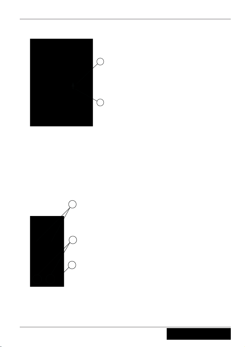
4.2 Assembly on the ZAdyn4C 011-032
" Push the mounting plate into the top groove of the ZAdyn4C
1
2
1 top groove
2 mounting plate
" Screw the M5 screws with washers two turns into the mounting plate.
" Fit the fastening plate in such a way that the M5 screws grips the recesses (3) in the
fastening plate. The chamfer (5) on the fastening plate must be on the right-hand
side.
" At the same time, hook in the hooks (2) on the faste
ning plate into the middle groove
on the ZAdyn4C. In doing so, take care that the washers are located between the
screw head and the fastening plate.
3
4
5
fastening plate
3
recesses
4 hooks
5 chamfer
" Press the fastening plate down so that the M5 screws
and the hooks snap in.
Original operating instructions
Brake Module Mechanical installation
R-TBA13_01-GB 1630 Part.-No. 00163414-GB
1
0/32
Page 11

" Tighten the M5 screws.
" Hook the Brake Module into the top hooks on the fastening plate (6) with the openings
at the side (7). Press the Brake Module down carefully until it is touching.
6
7
6 top hook of the fastening plate
7 openings of the Brake Module
" Remove the cover of the Brake Module.
" Tighten M4 screw.
8
8 M4 screw
Original operating instructions
Brake Module Mechanical installation
R-TBA13_01-GB 1630 Part.-No. 00163414-GB
1
1/32
Page 12
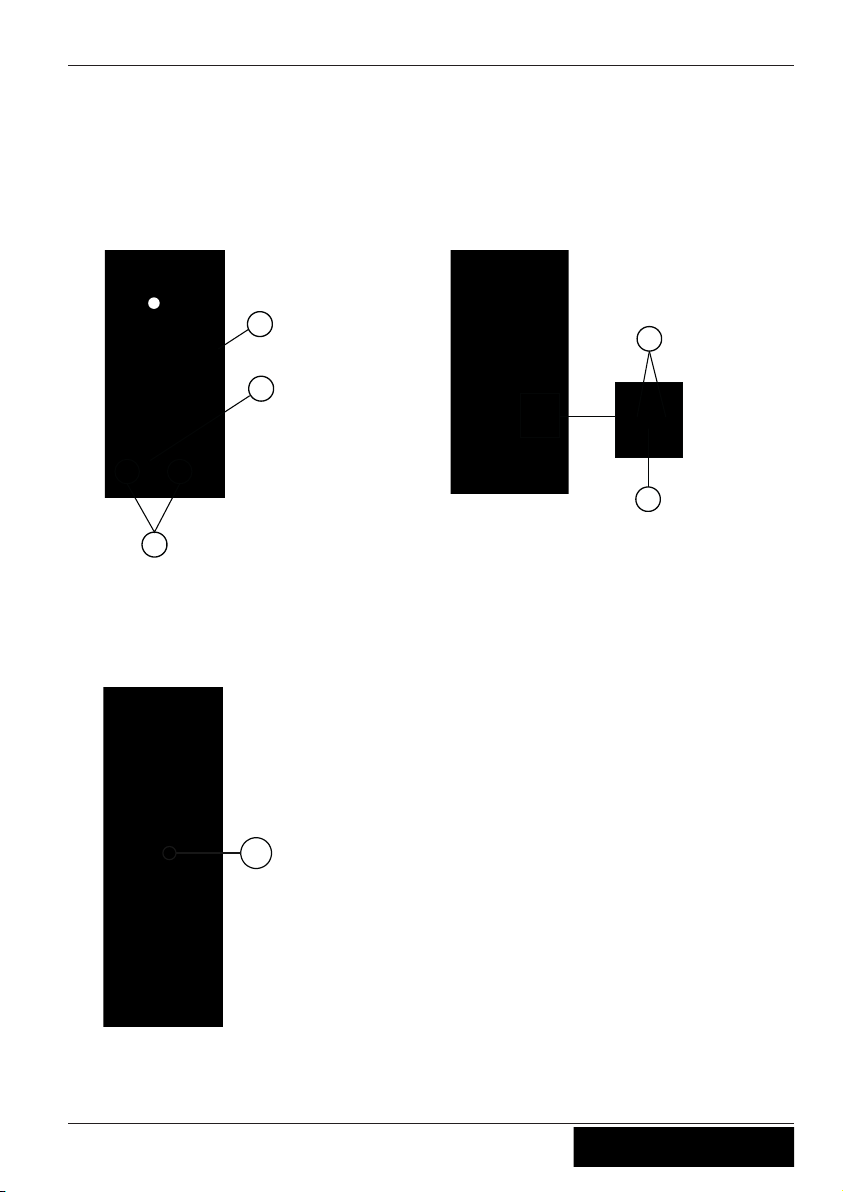
" Mount the cover of the Brake Module.
4.3 Assembly on the ZAdyn4C 040-074
" Insert the hook (1) of the fastening plate in the openings (2) on the right side of the
ZAdyn4C. Ensure here that the chamfer (3) of the fastening plate is on the right side.
The press-in nut (4) of the fastening plate grips the elongated hole (5) in the side of
the ZAdyn4C.
1
4
3
fastening plate
1 hooks
3 chamfer
4 Press-in nut
2
5
ZAdyn4C
2 Openings
5 Elongated hole
" Screw on the fastening plate with the screw M4 (6).
6
ZAdyn4C
6
M4 screw
Original operating instructions
Brake Module Mechanical installation
R-TBA13_01-GB 1630 Part.-No. 00163414-GB
1
2/32
Page 13

" Hook the Brake Module into the top hooks on the fastening plate (7) with the openings
at the side (8). Press the Brake Module down carefully until it is touching.
7
8
7 top hook of the fastening plate
8 openings of the Brake Module
" Remove the cover of the Brake Module.
" Tighten M4 screw.
9
9 M4 screw
" Mount the cover of the Brake Module.
Original operating instructions
Brake Module Mechanical installation
R-TBA13_01-GB 1630 Part.-No. 00163414-GB
1
3/32
Page 14
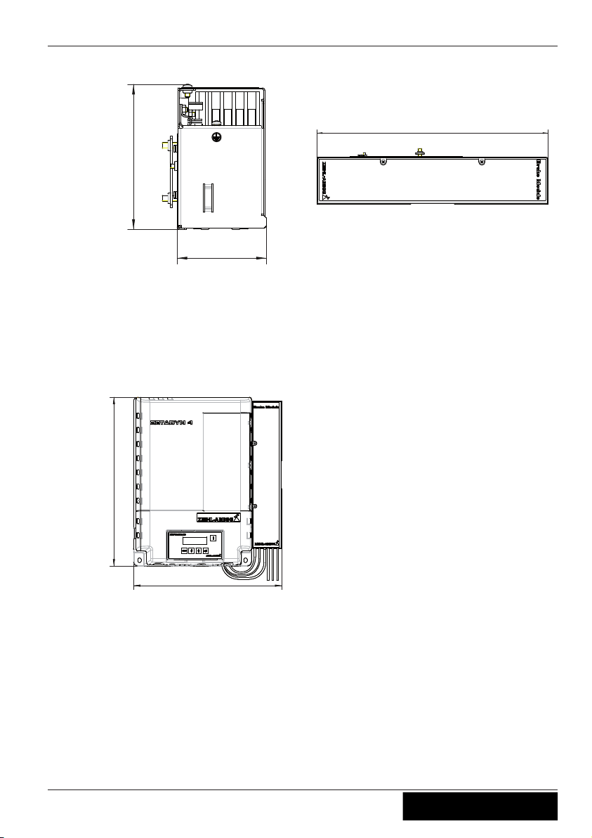
4.4 Dimensions / minimum clearances
126.1
77.5
Brake Module dimensions in mm
375
ZDSB01M0
377.5
429
377.5
429
ZAdyn4C 011-032 and
Brake Module dimensions in mm
ZAdyn4C 011-032 and
Brake Module minimum distances in mm
Original operating instructions
Brake Module Mechanical installation
R-TBA13_01-GB 1630 Part.-No. 00163414-GB
1
4/32
Page 15

ZAdyn4C 040-074 and
Brake Module dimensions in mm
ZDSB01M0
ZAdyn4C 040-074 and
Brake Module minimum distances in mm
Original operating instructions
Brake Module Mechanical installation
R-TBA13_01-GB 1630 Part.-No. 00163414-GB
1
5/32
Page 16

5 Electrical installation
Danger!
Never work on the Brake Module and the ZAdyn4C under voltage.
The intermediate circuit of the ZAdyn4C ( terminals X4: +DC / X2:-DC ) is still under
voltage even after switching off the ZAdyn4C.
Wait at least 3 minutes before working on the device
Danger!
Operating the Brake Module with the housing cover removed is prohibited because
energized, exposed parts are present inside the device. Disregarding this regulation can
lead to severe personal injury.
Caution!
Parts can be destroyed by electrostatic discharge.
Discharge yourself by suitable action before working on electrical components (connectors, etc.).
You can do this, for example, by touching earthed metal parts.
Work on electric components may only be carried out by trained electricians or by
persons instructed in electricity under the supervision of an electrician in accordance
with electrical engineering regulations.
A second person must always be present when working on energized parts or lines who
disconnects in case of emergency.
Inspect electrical equipment periodically: retighten loose connections – immediately
replace damaged lines and cables.
Always keep switch cabinets and all electrical supply facilities locked. Access is only
allowed for authorized persons using a key or special tool.
Never clean electrical equipment with water or similar liquids.
5.1 EMC-compatible installation
When correctly installed (see below), the device corresponds to the following standards:
•
EN 12015 Electromagnetic compatibility – product series standard for lifts, escalators,
moving pavements – spurious emission
•
EN 12016 Electromagnetic compatibility – product series standard for lifts, escalators,
moving pavements – interference immunity
The following points must be observed if the above mentioned standards are to be
adhered to:
•
Feed the voltage supply of the brake contactors through the line filter of the lift control
Original operating instructions
Brake Module Electrical installation
R-TBA13_01-GB 1630 Part.-No. 00163414-GB
1
6/32
Page 17
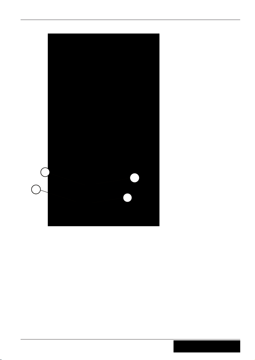
5.2 Terminal positions
1
2
3
4
Terminal positions
1 X-BA activation of brakes
2 X-K1 monitoring of brake contactors
3 X-K2 Voltage supply brakes / Break test, emergency rescue
4 X-SC activation of STO relays safety circuit
Original operating instructions
Brake Module Electrical installation
R-TBA13_01-GB 1630 Part.-No. 00163414-GB
1
7/32
Page 18
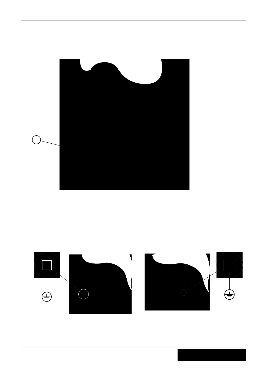
5.3 Strain relief
" A cable tie must be attached to all lines for strain relief. Fix the cable ties to the
recesses provided in the Brake Module housing (see fig.).
1
1 recesses for strain relief
5.4 Protective earth connection
The protective earth is already pre-assembled on the Brake Module.
" Connect the protective earth of the Brake Module to the protective earth connection of
the ZAdyn4C.
PE conductor connection ZAdyn4C 011-032
PE conductor connection ZAdyn4C 040-074
Original operating instructions
Brake Module Electrical installation
R-TBA13_01-GB 1630 Part.-No. 00163414-GB
1
8/32
Page 19
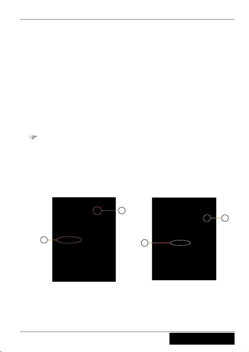
5.5 Connection motor brake
The maximum line length is 25 m.
" Connect the motor brakes to the terminal X-BA.
ZIEHL-ABEGG SE offers the pre-fabricated cable L-BA-...-HX-BM/SBM.
5.6 Connection ZAdyn4C
5.6.1 Activation of the brake contactor K3.
The brake contactor K3 is activated by a relay-output of the ZAdyn4C.
The cable L-SL-...-HX-BM/SBM-MB is already connected to the Brake Module.
" Connect this cable to the output with the function "
MB_Brake" at the terminal X-OUT
of the ZAdyn4C (see fig.).
See the ZAdyn4C Operating Instructions for further information about the allocation
of the outputs at connection terminal X-Out of the ZAdyn4C.
5.6.2 Triggering operation without contactors
The cable L-SL-...-HX-BM/SBM-STO for activating the inputs STO_A und STO_B is
already connected to the Brake Module.
" Plug this cable on the terminal X-STO of the ZAdyn4C
(see fig.).
1
2
Position of connection terminal ZAdyn4C 011032
1 X-Out digital outputs
2 X-STO Safe Torque Off
3
4
Position of connection terminal ZAdyn4C 040074
3 X-Out digital outputs
4 X-STO Safe Torque Off
Original operating instructions
Brake Module Electrical installation
R-TBA13_01-GB 1630 Part.-No. 00163414-GB
1
9/32
Page 20
5.7 Connection control system
5.7.1 Evaluation of the safety circuit
The operation without contactors of the ZAdyn4C requires the evaluation of the safety
circuit. The ralays K1 and K2 are activated depending on the safety circuit.
" Connect the safety circuit to the terminal X-SC.
ZIEHL-ABEGG SE offers the pre-fabricated cable L-SL-...-HX-BM/SBM-SC.
5.7.2 Contactor control
" Connect the contactor monitoring to the terminal X-K1.
ZIEHL-ABEGG SE offers the pre-fabricated cable L-SL-...-HX-BM/SBM-K.
5.7.3 Motor brake operating voltage
" Connect the voltage supply of the motor brakes to the terminals 9 and 10 of the
terminal X-K2.
5.7.4 Brake test / emergency rescue
" Connect the cable for the brake test / the emergency
operation to the terminals 5-8 of
the terminal X-K2.
5.8 Brakes
5.8.1 Brake contactors
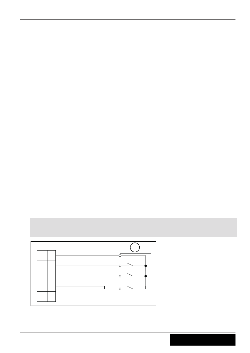
5.8.1.1 Brake release monitoring by the ZAdyn4C
With activated lock function the brake release monitoring fulfills the requirements for self
monitoring according to chapter 9.11.3 of EN81-1:2010 for brake elements for protection
against unintendend movement of the car.
X-MON, ZAdyn4C
+24V
_B
BR1
BR2
BR4
BR3
(13)
(12)
(11)
(10)
(9)
1
Connection of brake release monitor to the ZAdyn4C
1
Monitoring contacts
() terminal designation of connector
Original operating instructions
Brake Module Electrical installation
R-TBA13_01-GB 1630 Part.-No. 00163414-GB
2
0/32
Page 21

For further information about the brake release monitoring by the ZAdyn4C, see the
ZAdyn4C Operating Instructions, chapter "Electrical Installation/Brakes".
5.9 Process
K4
K3
STO_A
STO_B
BM
Z4
MB
K1+K2
Sicherheitskreis
Eingänge
Ausgänge
K1, K2 STO relay
K4 Brake contactor
K3 Brake contactor
STO_A Input STO_A
STO_B Input STO_B
MB_Brake Mechanical brake
Original operating instructions
Brake Module Electrical installation
R-TBA13_01-GB 1630 Part.-No. 00163414-GB
2
1/32
Page 22

5.10 Circuit suggestions Brake Module and ZAdyn4C
5.10.1 Actuation for brakes without over excitation
1 Power supply brakes
2 Power supply contactor / Safety circuit
3 Contactor control
4 manual brake release A
5 manual brake release B
6 Emergency operation / two-circuit test
7 Relay outputs
Original operating instructions
Brake Module Electrical installation
R-TBA13_01-GB 1630 Part.-No. 00163414-GB
2
2/32
Page 23

5.10.2 Actuation for brakes with over excitation
1 Power supply brakes
2 Power supply contactor / Safety circuit
3 Contactor control
4 manual brake release A
5 manual brake release B
6 Emergency operation / two-circuit test
7 Relay outputs
Original operating instructions
Brake Module Electrical installation
R-TBA13_01-GB 1630 Part.-No. 00163414-GB
2
3/32
Page 24

6 Enclosure
6.1 Technical Data Brake Module
BM
4-230-207 4-110-207 4-230-103 4-110-103
Electrical data
Mains connection voltage
b
rake, U~
[V] max. 253 100-250
Mains frequency [Hz] 50 / 60 (±1,5 Hz)
Holding
output voltage
[V] 0,9 x U~ 0,45 x U~
Output voltage at over
excitation
[V] - 0,9 x U~
Rated current [A] 2.0 2,0
Rated current at over excitation
[A] - 3.5
Rated power [W] 400 200
Nominal power at over
excitation
[W] - 700
Max. heat dissipation [W] < 20
Max. fuse protection
of contactors
[A] 6
Max. fuse protection
of brake
[A] FF5 (wire fuse)
Nominal voltage contactors K1-K4
[V] 1 ~ 230 1 ~ 110 1 ~ 230 1 ~ 110
Power consumption contactors K1 / K2
[VA] 0.7
Power consumption contactor K3
[VA] <= 5
Power consumption contactor K4
[VA] 7
Drop out time* contactor K3[ms] 40
Drop out time* contactor K4[ms] 19
BM
4-230-207 4-110-207 4-230-103 4-110-103
A
mbient conditions
The user must ensure that the specifie
d ambient conditions are observed.
Protection class
IP20
Original operating instructions
Brake Module Enclosure
R-TBA13_01-GB 1630 Part.-No. 00163414-GB
2
4/32
Page 25
Ambient conditions operation
[°C] 0 ... 45
Relative humidity [%] 90 / condensation prohibited
Installation height [m über
NN]
bis 2000 m
Storage and shipping
temperature
[°C] -20...+60 °C
Degree of soiling (in acc.
with DIN EN 61800-5-1)
2
P
hysical data
Weight [kg] 2.5
Dimensions h x w x d [mm] 375 x 78 x 128
* Period between field discharge of the magnet coil and interruption of the contacts
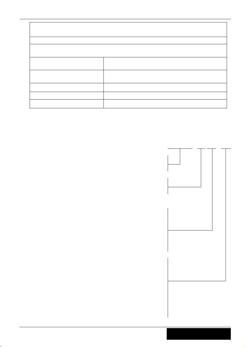
6.2 Type designation
BM
4
xxx/xxx
Brake Module
4th generation
Betriebsspannung Bremsschüt
ze
110: 110 VAC
230: 230 VAC
Motor brake operating voltage
103: 103/207 VDC
(
with over excita-
tion)
207: 207 VDC
Original operating instructions
Brake Module Enclosure
R-TBA13_01-GB 1630 Part.-No. 00163414-GB
2
5/32
Page 26

6.3 Part no.
Brake Module
BM 4-230/207 357263
BM 4-230/103 357264
BM 4-110/207 357265
BM 4-110/103 357266
Original operating instructions
Brake Module Enclosure
R-TBA13_01-GB 1630 Part.-No. 00163414-GB
2
6/32
Page 27

6.4 EU declaration of conformity - Translation -
(english)
A-KON16_09-GB
1633 Index 002
Manufacturer: ZIEHL-ABEGG SE
Heinz-Ziehl-Straße
74653 Künzelsau
Germany
The manufacturer shall bear sole responsibility for issuing this EU declaration of
conformity.
Product descript
ion:
Brake control BM
Type: BM 4-230/207
BM 4-110/207
BM 4-230/103
BM 4-110/103
The above mentioned products of this declaration fulfil
all relevant provisions of
the following Directives of the Union:
Low Voltage Directive 2014/35/EU
EMC Directive 2014/30/EU
The following harmonised standards have been used:
EN 61800-5-1:2007 Adjustable speed electrical power drive systems - Part 5-1:
Safety requirements Electrical, thermal and energy
EN 12015:2014 Electromagnetic compatibility –
Product family standard for lifts, escalators and moving walkways
– electromagnetic interference
EN 12016:2013 Electromagnetic compatibility-
Productfamily standard for lifts, escalators and moving walks Immunity
Original operating instructions
Brake Module Enclosure
R-TBA13_01-GB 1630 Part.-No. 00163414-GB
2
7/32
Page 28

This declaration relates exclusively to the product in the state in which it was placed on
the market, and excludes components which are added and/or operations carried out
subsequently by the final user.
The authorised representative for the assembly of the technical file is:
Mr. Roland Hoppenstedt (see above for address).
Kün
zelsau, 20.04.2016
(place and date of issue )
ZIEHL-ABEGG SE
Werner Bundscherer
Director Drive Division
(name, function)
ZIEHL-ABEGG SE
Roland Hoppenstedt
Technical Director Drive Division
(name, function)
(signature) (signature)
Original operating instructions
Brake Module Enclosure
R-TBA13_01-GB 1630 Part.-No. 00163414-GB
2
8/32
Page 29

Original operating instructions
Brake Module Enclosure
R-TBA13_01-GB 1630 Part.-No. 00163414-GB
2
9/32
Page 30

Original operating instructions
Brake Module Enclosure
R-TBA13_01-GB 1630 Part.-No. 00163414-GB
3
0/32
Page 31

Original operating instructions
Brake Module Enclosure
R-TBA13_01-GB 1630 Part.-No. 00163414-GB
3
1/32
Page 32

© by Ziehl-Abegg - - 00163414-GB - 1630 - - Subject to technical changes
Customer Service
phone +49 7940 16-308
fax +49 7940 16-249
[email protected]
Headquarters
ZIEHL-ABEGG SE
Heinz-Ziehl-Strasse · 74653 Künzelsau
Germany
phone +49 7940 16-0 · fax +49 7940 16-249
[email protected] · www.ziehl-abegg.com
 Loading...