

Page 1

INSTALLATION, OPERATION
AND TROUBLESHOOTING
MM9000 - CLEAR COMMAND USER MANUAL
MARINE PROPULSION SYSTEMS
Page 2

2 EN 3340.758.003a - 2014-11
COPYRIGHT
Released by After Sales dept.
Data subject to change without notice. We decline all responsibility for the use of non-original components or accessories wich
have not been tested and submitted for approval.
ZF reserves all rights regarding the shown technical information including the right to le industrial property right applications and the industrial property rights resulting from these in Germany and abroad.
© ZF Friedrichshafen AG, 2014.
Page 3

3
EN 3340.758.003a - 2014-11
TABLE OF CONTENT
MM9000 ClearCommand User Manual
Table of Contents
Table of Contents
Installation, Operation and Troubleshooting Manual
SW15623.OE
ClearCommand User Manual.......................................................... 1
Table of Contents................................................................................. 3
List of Figures....................................................................................... 7
List of Tables ...................................................................................... 13
Revision List ....................................................................................... 15
Preface ............................................................................................... 17
1 Introduction........................................................................................ 21
1.1 Basic Theory of Operation ...............................................................................................................21
1.2 System Features ..............................................................................................................................26
2 Operation ........................................................................................... 27
2.1 DC Power On ...................................................................................................................................27
2.2 Taking Command.............................................................................................................................27
2.3 Basic Operation ...............................................................................................................................28
2.4 Start Interlock (if used)....................................................................................................................29
2.5 Station Transfer ...............................................................................................................................30
2.6 Proportional Pause ..........................................................................................................................30
2.7 Warm-up Mode................................................................................................................................31
2.8 High/Low Idle ..................................................................................................................................32
2.9 One Lever Mode (Twin Screw) ........................................................................................................33
2.10 Engine Synchronization (Twin Screw).............................................................................................35
2.11 Control System’s Configurability .....................................................................................................37
2.12 Audible Tones ..................................................................................................................................39
2.13 Push Button Set Up .........................................................................................................................41
2.14 Visual System Diagnostics, Set Up And Status Indication ..............................................................41
2.15 Pluggable Connections....................................................................................................................42
2.16 Optional Features Operation ...........................................................................................................43
3 Plan the Installation ........................................................................... 45
3.1 System Requirements......................................................................................................................45
3.2 Installer Supplied Tools And Parts...................................................................................................50
3.3 DC Power Source ............................................................................................................................51
Page 4

4 EN 3340.758.003a - 2014-11
TABLE OF CONTENT
MM9000 ClearCommand User Manual
Table of Contents
4 Installation .........................................................................................53
4.1 Processor.........................................................................................................................................53
4.2 Control Head(s) ...............................................................................................................................53
4.3 Wire Harness Installation ................................................................................................................53
4.4 Hard-Wired Cable ............................................................................................................................58
4.5 Engine Stop Switches......................................................................................................................73
4.6 Push-Pull Cable Connections...........................................................................................................74
5 Set up Procedure ............................................................................... 77
5.1 Processor Components Used In Set Up ..........................................................................................77
5.2 Activating Set Up Mode...................................................................................................................80
5.3 Storing Values To Memory ..............................................................................................................80
5.4 Set Up Function Codes And Values .................................................................................................80
5.5 Field Service Test Unit (Break-out Box) and Multimeter Use..........................................................85
5.6 System Programming And Adjustments..........................................................................................86
5.7 Function Code E1 – Throttle in Neutral ...........................................................................................91
6 Dock Trials ....................................................................................... 113
6.1 Control Heads (Engines Stopped) .................................................................................................113
6.2 Start Interlock (Engines Stopped) .................................................................................................113
6.3 Engine Stop Switches....................................................................................................................113
6.4 Push-Pull Cables ............................................................................................................................113
6.5 High Idle ........................................................................................................................................113
6.6 Control Head Servo Command ......................................................................................................114
6.7 Control Head Solenoid Command .................................................................................................114
6.8 Throttle Pause Following Servo Shift ............................................................................................114
6.9 Throttle Pause Following Solenoid Shift .......................................................................................114
6.10 Trolling Valve .................................................................................................................................115
7 Sea Trials..........................................................................................117
7.1 Full Speed Setting - Servo Throttle................................................................................................117
7.2 Full Speed Setting - Electronic Throttle.........................................................................................117
7.3 Proportional Pause ........................................................................................................................117
7.4 Synchronization Test (Twin Screw Only).......................................................................................119
7.5 Sea Trial Report .............................................................................................................................124
F-226 9000 Series Sea Trial Report ................................................................................. 125
8 Control Options................................................................................ 131
8.1 External Alarm Capability ..............................................................................................................131
Page 5

5
EN 3340.758.003a - 2014-11
TABLE OF CONTENT
MM9000 ClearCommand User Manual
Table of Contents
8.2 Clutch Pressure Interlock ..............................................................................................................132
8.3 Station Expander (SE) ....................................................................................................................133
8.4 9001 Actuator Trolling Valve Control.............................................................................................134
9 Periodic Checks and Maintenance ..................................................135
9.1 Control Heads ................................................................................................................................135
9.2 Processor.......................................................................................................................................135
9.3 Power Supply.................................................................................................................................135
10 Troubleshooting ............................................................................... 137
10.1 General ..........................................................................................................................................137
10.2 Troubleshooting Questions............................................................................................................143
10.3 Troubleshooting Problem Resolution ............................................................................................144
10.4 Troubleshooting Diagnostic Menu ................................................................................................145
10.5 Troubleshooting Audible Tones .....................................................................................................148
10.6 Troubleshooting Station Transfer ..................................................................................................154
10.7 Troubleshooting Stuck Transfer Button.........................................................................................156
10.8 Error Codes....................................................................................................................................156
10.9 Basic Problem Causes And Solutions............................................................................................160
10.10 Problems Without Error Codes......................................................................................................172
10.11 Synchronization Troubleshooting ..................................................................................................175
10.12 Troubleshooting Wire Harnesses ..................................................................................................179
10.13 Processor Pigtails ..........................................................................................................................193
11 Appendix A - System Components and Specifications.................... 197
MMC-280 400 Series Control Head Variations................................................................ 199
MMC-329 MC2000 Series Standard Control Head Variations......................................... 205
MMC-307 700 Series Standard Control Head Variations ................................................ 209
MMC-279 400 Series Weather Mount Enclosure ............................................................ 215
Deutsch Connector Assembly.......................................................................................... 217
S-214 Automatic Power Selector Model: 13505 ............................................................. 219
Drawing 11488 DC Power Source Kit .............................................................................. 221
MMC-287 Grounding (Bonding) ...................................................................................... 231
MMC-288 References and Parts Source ......................................................................... 233
SER-161 Engine Tach Sender Req. .................................................................................. 235
MMC-289 Morse Clutch and Throttle Kit......................................................................... 237
MMC-290 Universal Mounting Kit ................................................................................... 239
MMC-345 43C Cable Conversion Kit ...............................................................................241
Page 6

6 EN 3340.758.003a - 2014-11
TABLE OF CONTENT
MM9000 ClearCommand User Manual
Table of Contents
MMC-343 Station Expander User Instructions ................................................................ 243
12 Appendix B - QFA & DVTP................................................................ 257
ENG-127 9000 Series Micro/ClearCommand Servo Throttle - Servo Clutch Qualitative Failure
Analysis, Design Verification Test Procedure and Periodic Safety Test .......................... 259
ENG-143 9000 Series ClearCommand Throttle - Solenoid Clutch Qualitative Failure Analysis,
Design Verification Test Procedure and Periodic Safety Test .........................................263
ENG-144 9000 Series Electronic Throttle - Servo Clutch Qualitative Failure Analysis, Design
Verification Test Procedure and Periodic Safety Test ..................................................... 267
ENG-145 9000 Series Servo Throttle - Solenoid Clutch, Qualitative Failure Analysis & Design
Verification Test Procedure ............................................................................................. 271
13 Appendix C - Sales and Service Information ................................... 275
MMC-123 Factory Authorized Sales & Service - North America ..................................... 277
MMC-151 Factory Authorized Service Centers - North America..................................... 283
MMC-172 Factory Authorized Sales & Service Centers - International........................... 295
MMC-165 Warranty ......................................................................................................... 303
MMC-163 Warranty Registration..................................................................................... 305
MM13927 Field Service Test Unit .................................................... 307
14 Appendix D - System Drawings ....................................................... 323
Drawing 12284 ClearCommand All Configuration Twin Screw System Drawing .............. 325
Page 7

7
EN 3340.758.003a - 2014-11
LIST OF FIGURES
MM9000 ClearCommand User Manual
List of Figures
List of Figures
Figure 1-1: Basic 9120 or 9122 ClearCommand System Diagram .......................................................................... 22
Figure 1-2: Basic 9121 ClearCommand System Diagram ....................................................................................... 23
Figure 1-3: Basic 9210 ClearCommand System Diagram ....................................................................................... 24
Figure 1-4: Basic 9211 ClearCommand System Diagram ....................................................................................... 25
Figure 1-5: Basic 9221 ClearCommand System Diagram ....................................................................................... 26
Figure 2-1: Station taking Command .....................................................................................................................27
Figure 2-2: Control Head Detents ..........................................................................................................................28
Figure 2-3: Control Head 20 Degree Troll Range - Type 1 ...................................................................................... 29
Figure 2-4: Control Head 35 Degree Troll Range - Type 2 ...................................................................................... 29
Figure 2-5: Control Head 45 Degree Troll Range - Type 3...................................................................................... 29
Figure 2-6: Control Head 55 Degree Troll Range - Type 4...................................................................................... 29
Figure 2-7: Remote Stations Before Transfer of Command.....................................................................................30
Figure 2-8: Remote Station Transfer after Transfer of Command............................................................................30
Figure 2-9: Control Head Warm-Up Mode ............................................................................................................. 31
Figure 2-10: Control Head Normal Operating Mode...............................................................................................31
Figure 2-11: High/Low Idle Mode Selection........................................................................................................... 32
Figure 2-12: Step A) One Lever Operation Mode ................................................................................................... 33
Figure 2-13: Step B) One Lever Operation Mode ................................................................................................... 34
Figure 2-14: Circuit Board Shield Layout................................................................................................................ 41
Figure 2-15: Standard Processor Pluggable Connections View ..............................................................................42
Figure 3-1: Processor Dimensions.......................................................................................................................... 45
Figure 4-1: Harness Plug Keying............................................................................................................................53
Figure 4-2: Start Interlock Connections..................................................................................................................54
Figure 4-3: Twin Screw Serial Harness Connections ..............................................................................................56
Figure 4-4: Liquid Tight Installation........................................................................................................................ 58
Figure 4-5: Standard Enclosure Cable Holes ..........................................................................................................58
Figure 4-6: Standard Circuit Board Hard-Wired Termination Points........................................................................59
Figure 4-7: 9120 and 9121 Enclosure Cable Holes ................................................................................................ 60
Figure 4-8: 9122 Enclosure Cable Holes ................................................................................................................ 61
Figure 4-9: 9210 and 9211 Enclosure Cable Holes ................................................................................................62
Figure 4-10: 9221 Enclosure Cable Holes ..............................................................................................................63
Figure 4-11: 9000 Series Circuit Board Hard-Wired Termination Points .................................................................64
Figure 4-12: Seven-Conductor Control Head Cable Shield Wire and Heat-Shrink................................................... 65
Figure 4-13: Clamp Views .....................................................................................................................................65
Figure 4-14: Terminal Strip Cable Connections...................................................................................................... 65
Figure 4-15: Two-Conductor Start Interlock Cable ................................................................................................. 66
Figure 4-16: Two-Conductor Power Cable .............................................................................................................67
Figure 4-17: Four-Conductor Serial Communication Cable.....................................................................................67
Figure 4-18: AC Type Tachometer Cable ............................................................................................................... 68
Figure 4-19: Open Collector Tachometer Cable ..................................................................................................... 69
Page 8

8 EN 3340.758.003a - 2014-11
LIST OF FIGURES
MM9000 ClearCommand User Manual
List of Figures
Figure 4-20: Clutch Cable Heat Shrink in Processor ............................................................................................... 69
Figure 4-21: Clutch Cable Plug Termination Connections....................................................................................... 70
Figure 4-22: Clutch/Troll Cable Heat Shrink in Processor .......................................................................................70
Figure 4-23: Clutch Cable Plug Termination Connections.......................................................................................71
Figure 4-24: Clutch Cable Heat Shrink in Processor ............................................................................................... 72
Figure 4-25: Clutch Cable Plug Termination Connections....................................................................................... 72
Figure 4-26: Engine Shield ....................................................................................................................................73
Figure 4-27: Processor Cable Clamp Rotation........................................................................................................ 74
Figure 4-28: Push-Pull Cable Interior Connection ................................................................................................... 74
Figure 4-29: Throttle Push-Pull Idle Orientation to Selector Lever...........................................................................75
Figure 4-30: Shift Push-Pull Cable Neutral Connection at Transmission.................................................................. 75
Figure 5-1: Typical Processor Cover....................................................................................................................... 77
Figure 5-2: Processor Shield Push Button and Display LED Locations .................................................................... 78
Figure 5-3: Display LED at Normal Operation......................................................................................................... 78
Figure 5-4: Display LED Designations .................................................................................................................... 78
Figure 5-5: Circuit Board Push Buttons .................................................................................................................. 79
Figure 5-6: Display LED Error Menu Example......................................................................................................... 79
Figure 5-7: Display LED Four Digit Value................................................................................................................79
Figure 5-8: Service Field Test Unit and Multimeter................................................................................................. 85
Figure 5-9: E1, E2, E3, E4, E6, L4 Processor, Test Unit, and Multimeter Connections ............................................ 86
Figure 5-10: L2, L3, C6, and C7 Processor, Test Unit, and Multimeter Connections ...............................................86
Figure 5-11: Display LED Function A0 Set Up Activated.........................................................................................87
Figure 5-12: Display LED Function A1 Set Up Activated.........................................................................................88
Figure 5-13: Display LED Function A2 Set Up Activated......................................................................................... 88
Figure 5-14: Display LED Function A3 Set Up Activated......................................................................................... 89
Figure 5-15: Display LED Function A4 Set Up Activated.........................................................................................89
Figure 5-16: Display LED Function E5 Set Up Activated......................................................................................... 90
Figure 5-17: Display LED Function E6 Set Up Activated......................................................................................... 90
Figure 5-18: Display LED Function E1 Set Up Activated......................................................................................... 91
Figure 5-19: Display LED Function E4 Set Up Activated......................................................................................... 91
Figure 5-20: Display LED Function E7 Set Up Activated......................................................................................... 92
Figure 5-21: Throttle Push-Pull Cable Orientation................................................................................................... 92
Figure 5-22: Example: Throttle Push-Pull Cable Fully Retracted Position for Idle.....................................................93
Figure 5-23: Display LED Function E0 Set Up Activated......................................................................................... 93
Figure 5-24: Display LED Function E2 Set Up Activated......................................................................................... 93
Figure 5-25: Throttle Push-Pull Cable Full Throttle Position ....................................................................................94
Figure 5-26: Display LED Function E3 Set Up Activated......................................................................................... 94
Figure 5-27: Display LED Function E0 Set Up Activated......................................................................................... 95
Figure 5-28: Display LED Function E2 Set Up Activated......................................................................................... 95
Figure 5-29: Display LED Function E3 Set Up Activated......................................................................................... 96
Figure 5-30: Display LED Function C0 Set Up Activated.........................................................................................96
Figure 5-31: Display LED Function C1 Set Up Activated.........................................................................................97
Page 9

9
EN 3340.758.003a - 2014-11
LIST OF FIGURES
MM9000 ClearCommand User Manual
List of Figures
Figure 5-32: Display LED Function C2 Set Up Activated.........................................................................................97
Figure 5-33: Display LED Function C3 Set Up Activated.........................................................................................98
Figure 5-34: Display LED Function C4 Set Up Activated.........................................................................................99
Figure 5-35: Clutch Push-Pull Cable Orientation ..................................................................................................100
Figure 5-36: Display LED Function C5 Set Up Activated.......................................................................................100
Figure 5-37: Clutch Push-Pull Cable Ahead Position ............................................................................................ 101
Figure 5-38: Display LED Function C6 Set Up Activated.......................................................................................101
Figure 5-39: Clutch Push-Pull Cable Astern Position ............................................................................................102
Figure 5-40: Display LED Function C7 Set Up Activated.......................................................................................102
Figure 5-41: Display LED Function C5 Set Up Activated.......................................................................................103
Figure 5-42: Display LED Function C6 Set Up Activated.......................................................................................103
Figure 5-43: Display LED Function C7 Set Up Activated....................................................................................... 104
Figure 5-44: Display LED Function L0 Set Up Activated. ...................................................................................... 105
Figure 5-45: Control Head 20 Degree Troll Range - Type 1 .................................................................................. 105
Figure 5-46: Control Head 35 Degree Troll Range - Type 2 .................................................................................. 105
Figure 5-47: Control Head 45 Degree Troll Range - Type 3..................................................................................105
Figure 5-48: Control Head 55 Degree Troll Range - Type 4 .................................................................................. 105
Figure 5-49: Display LED Function L1 Set Up Activated ....................................................................................... 106
Figure 5-50: Display LED Function L1 Set Up Activated ....................................................................................... 107
Figure 5-51: Display LED Solenoid Function L2 Set Up Activated......................................................................... 107
Figure 5-52: Display LED Servo Function L2 Set Up Activated.............................................................................. 107
Figure 5-53: Display LED Solenoid Function L3 Set Up Activated.........................................................................108
Figure 5-54: Display LED Servo Function L3 Set Up Activated.............................................................................. 108
Figure 5-55: Display LED Solenoid Function L4 Set Up Activated......................................................................... 109
Figure 5-56: Display LED Function L6 Set Up Activated ....................................................................................... 110
Figure 5-57: Display LED Function L6 Set Up Activated .......................................................................................110
Figure 8-1: External Alarm Connections Processor Hard-Wired Example .............................................................131
Figure 8-2: External Alarm Connections Processor Hard-Wired Example .............................................................131
Figure 8-3: Clutch Pressure Switch with Processor Harness Diagram................................................................... 133
Figure 8-4: Clutch Pressure Switch with Processor Hard-Wired Diagram .............................................................133
Figure 10-1: 9120 and 9122 Basic Twin Screw, Two Station Diagram ................................................................. 137
Figure 10-2: 9121 Basic Twin Screw, Two Station Diagram................................................................................. 138
Figure 10-3: 9210 Basic Twin Screw, Two Station Diagram................................................................................. 139
Figure 10-4: 9211 Basic Twin Screw, Two Station Diagram.................................................................................140
Figure 10-5: 9221 Basic Twin Screw, Two Station Diagram................................................................................. 141
Figure 10-6: Display Function Code List...............................................................................................................146
Figure 10-7: Display Troubleshooting Function .................................................................................................... 146
Figure 10-8: Display Troubleshooting Function Blinking....................................................................................... 146
Figure 10-9: Example Display of Applied Battery Voltage..................................................................................... 146
Figure 10-10: Example Display of Tach Sensor Frequency ...................................................................................146
Figure 10-11: Example Display Control Head Lever Current Positions .................................................................. 147
Figure 10-12: Example Display Control Head Transfer Button Status View ...........................................................147
Page 10

10 EN 3340.758.003a - 2014-11
LIST OF FIGURES
MM9000 ClearCommand User Manual
List of Figures
Figure 10-13: Example Display Software Revision Level View .............................................................................. 147
Figure 10-14: Display Examples of Remote Stations ............................................................................................ 149
Figure 10-15: Display Examples of Remote Stations A/D Value............................................................................150
Figure 10-16: Display Station A/D’s No Station Transfer Button Depressed.......................................................... 155
Figure 10-17: Example Display Station A/D’s Transfer Button Depressed for Stations 1 - 4 .................................. 155
Figure 10-18: Display Station A/D/s Transfer Button Depressed for Station 5.......................................................155
Figure MMC-280-1: Part Numbering Configurations ........................................................................................... 199
Figure MMC-280-2: Detents Available ................................................................................................................. 199
Figure MMC-280-3: Dimensions.......................................................................................................................... 200
Figure MMC-280-4: Terminal Connections .......................................................................................................... 201
Figure MMC-280-5: AFT Facing Control Head ..................................................................................................... 201
Figure MMC-329-1: Part Numbering Configurations Detents Available ................................................................ 205
Figure MMC-329-2: Dimensions.......................................................................................................................... 206
Figure MMC-329-3: Terminal Connections ..........................................................................................................207
Figure MMC-329-4: AFT Facing Control Head ..................................................................................................... 207
Figure MMC-307-1: Part Numbering Configurations ............................................................................................ 209
Figure MMC-307-2: Detents Available................................................................................................................. 209
Figure MMC-307-3: Dimensions .......................................................................................................................... 209
Figure MMC-307-4: Dual Control Head Connections ...........................................................................................211
Figure MMC-307-5: Aft Facing Control Head.......................................................................................................211
Figure MMC-343-1: Station Expander..................................................................................................................244
Figure MMC-343-2: Station Expander Harness Connector Locations ..................................................................246
Figure MMC-343-3: Harness Plug Connectors ..................................................................................................... 246
Figure MMC-343-4: Station Expander Dimensions............................................................................................... 247
Figure MMC-343-5: Station Expander Display LED and Arrow Push Buttons........................................................ 249
Figure MMC-343-6: Display LED at Normal Operation ......................................................................................... 250
Figure MMC-343-7: Display LED Designations..................................................................................................... 250
Figure MMC-343-8: Error Menu Example ............................................................................................................251
Figure MMC-343-9: Display LED Four Digit Value ................................................................................................ 251
Figure MMC-343-10: Display Normal Operating Condition .................................................................................. 251
Figure MMC-343-11: Display Function Menu Activated ....................................................................................... 252
Figure MMC-343-12: Display with Set up Activated.............................................................................................252
Figure MMC-343-13: Display with A0 - Station Expander Identification Set Up Activated .................................... 253
Figure MM13927-1: .Service Field Test Unit (Break-out Box)...............................................................................311
Figure MM13927-2: CruiseCommand Connector Locations .................................................................................311
Figure MM13927-3: Example of CLEARCommand Pigtail Locations..................................................................... 312
Figure MM13927-4: Throttle Connection (DC Voltage) ........................................................................................313
Figure MM13927-5: Throttle Connection (Current mA)........................................................................................314
Figure MM13927-6: Throttle Connection (PWM with DC Voltmeter).................................................................... 315
Figure MM13927-7: Throttle connection (PWM with Duty Cycle Meter) .............................................................316
Figure MM13927-8: Throttle Connection (Frequency Hz).....................................................................................317
Figure MM13927-9: Clutch Connections Neutral Solenoid...................................................................................317
Page 11

11
EN 3340.758.003a - 2014-11
LIST OF FIGURES
MM9000 ClearCommand User Manual
List of Figures
Figure MM13927-10: Clutch Connections Ahead Solenoid..................................................................................318
Figure MM13927-11: Clutch Connections Astern Solenoid.................................................................................. 319
Figure MM13927-12: Troll Connections Troll On/Off Solenoid ............................................................................. 319
Figure MM13927-13: Troll Connections (Proportional Solenoid) ......................................................................... 320
Figure MM13927-14: 2-Speed Connections ........................................................................................................321
Page 12

12 EN 3340.758.003a - 2014-11
Page 13

13
EN 3340.758.003a - 2014-11
LIST OF TABLES
MM9000 ClearCommand User Manual
List of Tables
List of Tables
Table 4-1: ClearCommand Processor Optional Hard-Wiring Cable List................................................................... 60
Table 4-2: Processor Circuit Board Terminal Strip Color Coded Connections for Remote Stations .......................... 66
Table 4-3: Processor Circuit Board Terminal Strip Color Coded Connections for Serial Communication .................. 68
Table 4-4: Processor Circuit Board Terminal Strip Color Coded Connections for Tachometer..................................69
Table 4-5: Clutch Termination Table ......................................................................................................................70
Table 4-6: Clutch/Troll Termination Table............................................................................................................... 71
Table 4-7: Clutch Termination Table ...................................................................................................................... 72
Table 4-8: Throttle Termination Table ....................................................................................................................73
Table 5-1: Function Codes.....................................................................................................................................80
Table 5-2: Processors Function Code Defaults .......................................................................................................83
Table 5-3: Solenoid Error Status Enable...............................................................................................................111
Table 6-1: Shaft RPM at Idle ................................................................................................................................ 115
Table 6-2: Shaft RPM at Idle ................................................................................................................................ 116
Table 7-1: Shaft RPM at Idle ................................................................................................................................ 120
Table 7-2: Troll Valve Adjustments.......................................................................................................................121
Table F-226-1: Vessel Information ....................................................................................................................... 125
Table F-226-2: Processor Information ..................................................................................................................125
Table F-226-3: Power Supply............................................................................................................................... 126
Table F-226-4: Dock Trials...................................................................................................................................126
Table F-226-5: Record at Dock ............................................................................................................................ 126
Table F-226-6: Sea Trials ..................................................................................................................................... 127
Table F-226-7: Record during Sea Trial................................................................................................................127
Table F-226-8: Processor Parameters Record ...................................................................................................... 127
Table 9-1: Fully Charged Battery..........................................................................................................................136
Table 10-1: ClearCommand Processor Push-Pull Reference .................................................................................142
Table 10-2: Examples of Components (Internal/External).....................................................................................145
Table 10-3: Control Head Lever A/D Counts.........................................................................................................155
Table 10-4: Clutch Solenoid Control System Error Codes ..................................................................................... 156
Table 10-5: Troll Solenoid Control System Error Codes ........................................................................................ 156
Table 10-6: Basic Control System Error Codes ..................................................................................................... 157
Table 10-7: Servo 1 Error Codes .......................................................................................................................... 159
Table 10-8: Servo 2 Error Codes .......................................................................................................................... 159
Table 10-9: Basic Control System Problem Causes and Solutions ........................................................................160
Table 10-10: Servo 2 Throttle Problem Causes and Solutions............................................................................... 169
Table 10-11: Servo 1 Clutch Problem Causes and Solutions ................................................................................169
Table 10-12: Servo 2 Troll Problem Causes and Solutions....................................................................................170
Table 10-13: Servo 2 Troll Problem Causes and Solutions....................................................................................171
Table 10-14: Wire Harness - Serial Communication (p/n 13316-XX)....................................................................179
Table 10-15: Wire Harness - Serial Communication Multi-Screw (p/n 15544-XX) ................................................ 180
Table 10-16: Wire Harness - Serial Communication / CANtrak (p/n 70422-XX).................................................... 181
Page 14

14 EN 3340.758.003a - 2014-11
LIST OF TABLES
MM9000 ClearCommand User Manual
List of Tables
Table 10-17: Wire Harness - Throttle, Voltage (IVECO, Cummins) (p/n 13432-XX)............................................... 181
Table 10-18: Wire Harness- Throttle, Current (MAN, MTU) (p/n 13494-XX)........................................................ 182
Table 10-19: Wire Harness - Throttle, Voltage (Cummins Plug), (p/n 13565-XX).................................................. 182
Table 10-20: Voltage Throttle Harness Pin-Out (p/n 14148-XX) ........................................................................... 183
Table 10-21: Wire Harness - Throttle (Pulse width modulation [PWM]), (p/n 13533-XX) .....................................183
Table 10-22: Voltage Throttle Harness Pin-Out (p/n 71262-XX) ........................................................................... 184
Table 10-23: Cable, throttle, MAN EDC (p/n 14421-XX) ...................................................................................... 184
Table 10-24: Wire Harness - Throttle Current w/ Mag Pickup, Man (Non-Common Rail) (p/n 14363-XX)............. 185
Table 10-25: Wire Harness - Clutch, Ahead, Astern (p/n 15719-XX)....................................................................186
Table 10-26: Wire Harness - Ahead / Astern Troll on/off Command (p/n 15725-XX) ............................................ 186
Table 10-27: Wire Harness - Clutch with Troll Command (p/n 15732-XX)............................................................ 187
Table 10-28: Wire Harness- Clutch, Ahead, Astern, Troll Command, Troll On-Off (p/n 70390-XX) .......................188
Table 10-29: Wire Harness- Clutch, Ahead, Astern, ZFF Transmission (p/n 70673-XX)........................................189
Table 10-30: Power, Start Interlock Harness Pin-Out (p/n 13756-XX) ..................................................................189
Table 10-31: Wire Harness - Power, SI & Clutch Pressure Switch (p/n 13552-XX) ...............................................190
Table 10-32: Wire Harness - Power, SI, Clutch Pressure Switch & Alarm (p/n 13631-XX) .................................... 190
Table 10-33: Wire Harness- Power Use W/existing St Intlk Only (p/n 15023-XX).................................................191
Table 10-34: Wire Harness - Control Head One Connector (p/n 13557-XX) .........................................................191
Table 10-35: Wire Harness - Control Head Two Connectors (p/n 14261-XX) ....................................................... 192
Table 10-36: Wire Harness - Serial Communication, Processor Lead (p/n 15705-XX) ..........................................193
Table 10-37: Wire Harness - Throttle, Processor Lead (p/n 15703-XX).................................................................194
Table 10-38: Wire Harness - Solenoid Clutches, Processor Lead (p/n 15701-XX).................................................194
Table 10-39: Power, Start Interlock, Clutch Oil Pressure Switch, and Alarm Pigtail Pin-Out (p/n 15710-XX)......... 195
Table 10-40: Wire Harness - Control Head, Processor Lead (p/n 15706-XX).......................................................196
Table 10-41: Wire Harness - Mag Pickup, Processor Lead (p/n 15704-XX) .......................................................... 196
Table MMC-343-1: Functions List ........................................................................................................................ 252
Table MMC-343-2: Troubleshooting Functions .................................................................................................... 253
Page 15

15
EN 3340.758.003a - 2014-11
REVISION LIST
MM9000 ClearCommand User Manual
Revision List
Revision List
Revision Date Revision Description
Rev - 11/03 Revision - was a PRELIMINARY manual printed to support Production.
Rev A 4/03 Released and Signed Off.
Rev B 6/04 Updated with most current Forms and Manual Modules.
Rev C 8/04 Included ELR 1167 and 1150
Rev C.1 2/08
Replaced Field Service Test Unit (MM13927) manual with current revision (reformatted).
Replaced forms MMC-172 International FASSC List, MMC-165 Warranty Policy with current revision.
Rev C.2 5/08 Replaced MMC-280 & MMC-329 Control Head Variations current revision.
Rev C.3 1/09
Replaced MMC-165 - Rev G 1/09 Electronic Propulsion Systems Limited Warranty
Replaced MMC-123, MMC-151, MMC-172 - Factory Authorized Sales & Service Center Lists
Rev C.4 04/09 Replaced MMC-123, MMC-151, MMC-172 - Factory Authorized Sales & Service Center Lists
Rev C.5 09/09 Reviewed and replaced all external forms and documents with current revisions.
Rev C.6 05/11
Reformatted to FrameMaker9, Updated Software number, Revised preface per ELR00113, updated
all external documents with current revision level, Revised per ELR00048
Rev C.7 09/11 Added MMC-343, changes made per ELR00144
Rev C.8 01/13 Changed name to ZF Marine Propulsion Systems Miramar, LLC
Page 16

16 EN 3340.758.003a - 2014-11
Page 17

17
EN 3340.758.003a - 2014-11
PREFACE
MM9000 ClearCommand User Manual
Preface
Preface
ClearCommand Processor List
The processors for the systems listed below have software which includes several featured options.
Information about these options is contained in this manual, along with all standard instructions for 9000
series Processors. All vessels with ClearCommand Processors will not necessarily use all the featured options.
Decide on their utility based upon your application.
Below is an example of the 9000 Series Part Numbering system. This is just a guide, there are more options
available than shown below.
For example a 91212 is a ClearCommand Processor with Mechanical Engine, Solenoid Clutch, Mechanical
Troll and 2 stations. Each number in the part number signifies a different quality of the processor that fits your
needs. The last number in each Processor part number is the number of stations that are being used.
Available Options for the Processors Covered in this Manual
• Dynamic Positioning Interface
• Station 4 / Joystick Interface
• CANtrak Display
• Engine Room/Remote Switch (Station 1 only)
• Station 2 Lockout
• Speed Boost — Loaded w/Software
• Fixed Neutral Delay — Loaded w/Software
IMPORTANT: Keep this manual in a safe place for future reference. It contains essential information about the
installation and operation of the ZF Marine Propulsion Systems Miramar control system for your vessel.
9000 Series Part Numbering / Identification Guide
Part Number
90010 91000 91102 91202
91212 92000 92102 92112 92212 95232 96232
Engine /
Throttle
None 0 X
Mechanical 1 XXXX
Electrical 2
XXXX
Premium Mechanical 5
X
Premium Electrical 6
X
Gear /
Clutch
None 0 XX
X
Mechanical 1 X
XX
Solenoid 2 X
X XX X
Mechanical Gear /
Solenoid 2 Speed
3
Solenoid Gear /
Solenoid 2 Speed
4
Troll
None 0 XXX
XX
Mechanical 1 X
XX
Solenoid 2
Autotroll 3 XX
Mechanical Governed
Troll
5
Solenoid Governed
Troll
6
Page 18
18 EN 3340.758.003a - 2014-11
PREFACE
MM9000 ClearCommand User Manual
Preface
Conventional Symbols Used in the Manual
Throughout this manual special attention should be paid to the following symbols.
Important Information
WARNING: Personal Injury may result if this message is disregarded.
CAUTION: Damage to equipment may occur if this message is disregarded.
IMPORTANT: Contains essential Information about a topic.
NOTE: Contains noteworthy information that may help to clarify a topic.
WARNING: Personal Injury could occur if the following steps are not followed exactly.
CAUTION: On Control Systems with more than one Processor, ZF Marine Propulsion Systems Miramar highly
recommends that ALL UNITS utilize the same software revision for each Processor.
CAUTION: Electro-static discharge can damage this equipment. Personnel working on this equipment must be
grounded to the chassis with an Anti-static Wrist Strap.
CAUTION: Disconnect the Power from the Processor whenever welding is being done on the vessel. Failure to
do so can cause permanent damage to the Processor.
CAUTION: This equipment is designed to work with other ZF Marine Propulsion Systems Miramar designed
equipment. DO NOT operate this equipment with any other manufacturers equipment unless approved so in
writing by ZF Marine Propulsion Systems Miramar Engineering Department.
Page 19
19
EN 3340.758.003a - 2014-11
PREFACE
MM9000 ClearCommand User Manual
Preface
Optional Features Information
How to Use the Manual
This manual is written describing all possible options available for this processor. Your vessel may not require
all of these options. Refer only to the sections that apply to your vessel. If you wish to use one of the available
options listed, please contact a technician from ZF Marine Propulsion Systems Miramar Sales & Service
Organization (SSO). For more information on an SSO in your area, please see Section 13: Appendix C - Sales
and Service Information.
WARNING: If the Dynamic Positioning (DP) Interface option is being used, it is the operator’s responsibility to
operate the vessel per the DP system manufacturer’s requirements. Please call your ZF Marine Propulsion
Systems Miramar representative for any questions with any installation/operational questions prior to Sea
Trials.
WARNING: If the DP/JS Interface option is being used, it is the operator’s responsibility to operate the vessel
per the DP system manufacturer’s requirements. Please call your ZF Marine Propulsion Systems Miramar
representative for any questions with any installation/operational questions prior to Sea Trials.
CAUTION: The DP pigtail MUST NOT be used to connect any other device such as a remote station Control
Head. Failure to meet this requirement will nullify the Processor warranty, cause an unsafe operating condition
and/or damage the Processor.
CAUTION: If the DP option is being utilized with a multi-screw application, ALL Processors MUST HAVE the DP
pigtail connected to the DP System. Failure to comply with this requirement could cause an unsafe operating
condition with possible severe personal injury and/or property damage.
CAUTION: If the DP option with Troll is being utilized with a multi-screw application, the Dynamic Positioning
System is responsible for any transmission damage that may occur due to Trolling with one screw and
operating with the clutch fully engaged on another screw (i.e., “dragging” a screw through the water).
CAUTION: Misapplication of the Speed Boost feature can damage the transmission or other equipment. Before
using Speed Boost, the transmission representative must be consulted about its use, and any limitations on
clutch engagement as a function of engine speed. The person(s) implementing Speed Boost have the
responsibility for ensuring it is properly adjusted and for any damage that might occur.
NOTE: ZF Marine Propulsion Systems Miramar is not liable for any damage incurred if these notices are not
followed exactly.
Page 20

20 EN 3340.758.003a - 2014-11
Page 21

21
EN 3340.758.003a - 2014-11
INTRODUCTION
MM9000 ClearCommand User Manual
Introduction
1 Introduction
This manual is written to document every possible system option.
Your system may not include every available option for single or twin screw reverse reduction gear
applications.
Only those sections that apply to your specific installation are relevant to your vessel.
If additional options described within this manual are desired, contact your dealer for availability/
compatibility with your system.
1.1 Basic Theory of Operation
The ClearCommand Marine Propulsion Control System (hereafter referred to as ClearCommand or System) is
electronic and requires a 12 or 24 VDC power supply, one Processor per engine/clutch and one Control Head
per remote station. The ClearCommand commands the vessel’s throttle and shift using a single Control Head
lever.
One electric cable per Control Head lever connects the remote station(s) to the Processor(s). Only one remote
station will have command at a given time and the Station-in-Command is indicated by a red light located on
the Control Head. Station transfer is accomplished by pressing the Control Head mounted transfer button.
1.1.1 9120 Processor (Throttle-Servo 2, Shift-Solenoid) or 9122 Processor (Throttle-Servo 2,
Shift-Solenoid, Troll-Solenoid).
The 9120 or 9122 System is designed for pleasure and light commercial marine vessels that require
remote control of:
9120
• mechanically actuated engines
• solenoid activated clutches
9122
• mechanically actuated engines
• solenoid activated clutches
• solenoid activated trolling valves
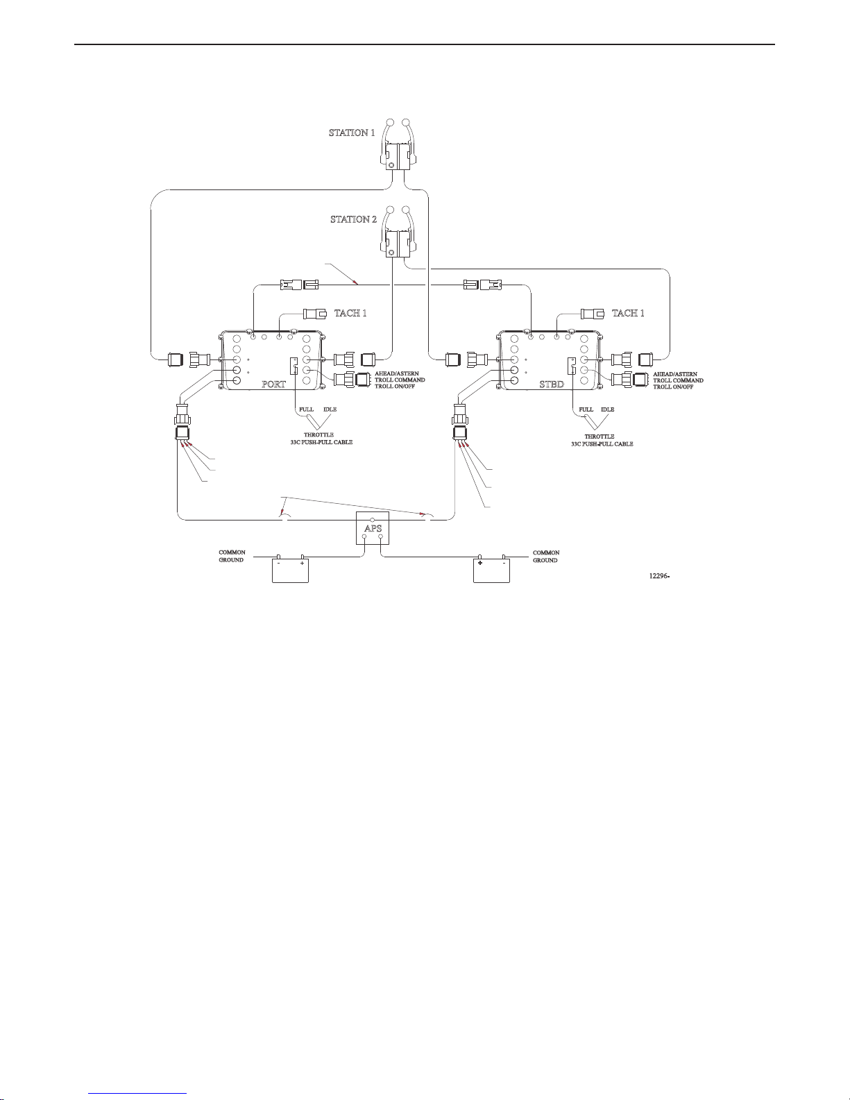
The 9120 or 9122 Processor is typically mounted in the engine room area and is connected
mechanically to the vessel’s main engine throttle selector lever with standard 33C type push-pull
cables.
The 9120 Processor controls the electrical Ahead and Astern Shift Solenoids at the transmission, via
electric cable.
Page 22
22 EN 3340.758.003a - 2014-11
INTRODUCTION
MM9000 ClearCommand User Manual
Introduction
The 9122 Processor controls the electrical Transmission and Trolling Valve Solenoids for shift and
trolling functions, via electric cable.
Figure 1-1: Basic 9120 or 9122 ClearCommand System Diagram
IDLEFULL
33C PUSH-PULL CABLE
IDLE
FULL
THROTTLE
STBD
STATION 2
STATION 1
PORT
12296-
SERIAL COMMUNICATION
10 AMP CIRCUIT BREAKERS
(BY OTHERS)
COMMON
GROUND
COMMON
GROUND
+
-
+
-
APS
CLUTCH PRES.
START INTERLOCK
ALARM
START INTERLOCK
CLUTCH PRES.
ALARM
TACH 1 TACH 1
AHEAD/ASTERN
TROLL COMMAND
TROLL ON/OFF
AHEAD/ASTERN
TROLL COMMAND
TROLL ON/OFF
33C PUSH-PULL CABLE
THROTTLE
Page 23
23
EN 3340.758.003a - 2014-11
INTRODUCTION
MM9000 ClearCommand User Manual
Introduction
1.1.2 9121 Processor (Throttle-Servo 2, Shift-Solenoid, Troll-Servo 1)
The 9121 System is designed for pleasure and light commercial marine vessels that require remote
control of:
• mechanically actuated engines
• solenoid activated clutches
• mechanical trolling valves.
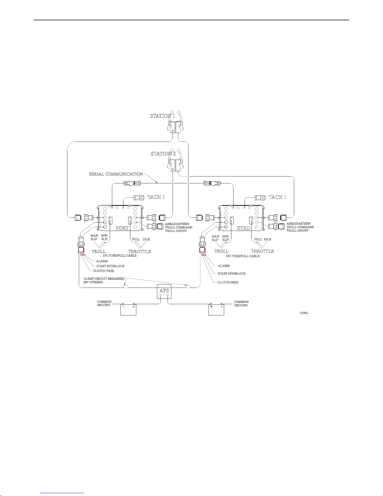
The Processor is typically mounted in the engine room area and is connected mechanically to the
vessel’s main engine throttle selector lever and trolling valve with standard 33C type push-pull cables.
The transmission is controlled via electrical cables connected to the Ahead and Astern Shift
Solenoids.
Figure 1-2: Basic 9121 ClearCommand System Diagram
IDLEFULL
33C PUSH/PULL CABLE
33C PUSH/PULL CABLE
IDLE
FULL
THROTTLETROLL
STBD
STATION 2
STATION 1
PORT
12295-
SERIAL COMMUNICATION
10 AMP CIRCUIT BREAKERS
(BY OTHERS)
COMMON
GROUND
COMMON
GROUND
+
-
+
-
APS
CLUTCH PRES.
START INTERLOCK
ALARM
START INTERLOCK
CLUTCH PRES.
ALARM
TACH 1 TACH 1
MAX
SLIP
MIN
SLIP
AHEAD/ASTERN
TROLL COMMAND
TROLL ON/OFF
AHEAD/ASTERN
TROLL COMMAND
TROLL ON/OFF
MAX
SLIP
MIN
SLIP
THROTTLETROLL
Page 24
24 EN 3340.758.003a - 2014-11
INTRODUCTION
MM9000 ClearCommand User Manual
Introduction
1.1.3 9210 Processor (Throttle-Electronic, Shift-Servo 1)
The 9210 System is designed for pleasure and light commercial marine vessels that require remote
control of:
• electronic engine governors
• mechanically actuated clutches
The Processor is typically mounted in the engine room area and is connected to the electronic
governor with a two-conductor, shielded, electric cable.
The transmission is controlled mechanically using standard 33C type push-pull cable.
Figure 1-3: Basic 9210 ClearCommand System Diagram
33C PUSH/PULL CABLE
33C PUSH/PULL CABLE
SHIFT
F
N
RFR
N
STBD
STATION 2
STATION 1
PORT
12294-
SERIAL COMMUNICATION
10 AMP CIRCUIT BREAKERS
(BY OTHERS)
COMMON
GROUND
COMMON
GROUND
+
-
+
-
APS
CLUTCH PRES.
START INTERLOCK
ALARM
START INTERLOCK
CLUTCH PRES.
ALARM
TACH 1 TACH 1
THROTTLETHROTTLE
SHIFT
Page 25
25
EN 3340.758.003a - 2014-11
INTRODUCTION
MM9000 ClearCommand User Manual
Introduction
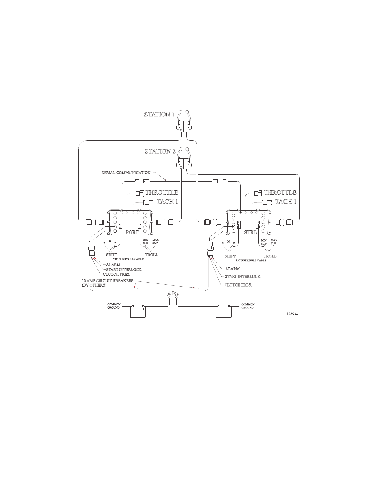
1.1.4 9211 Processor (Throttle - Electronic, Shift - Servo 1, Troll - Servo 2)
The 9211 System is designed for pleasure and light commercial marine vessels that require remote
control of:
• electronic engine governors
• mechanically actuated clutches
• mechanically actuated trolling valves.
The Processor is typically mounted in the engine room area and is connected to the electronic
governor with a two-conductor, shielded, electric cable.
The transmission and trolling valve are controlled mechanically using a standard 33C type push-pull
cable.
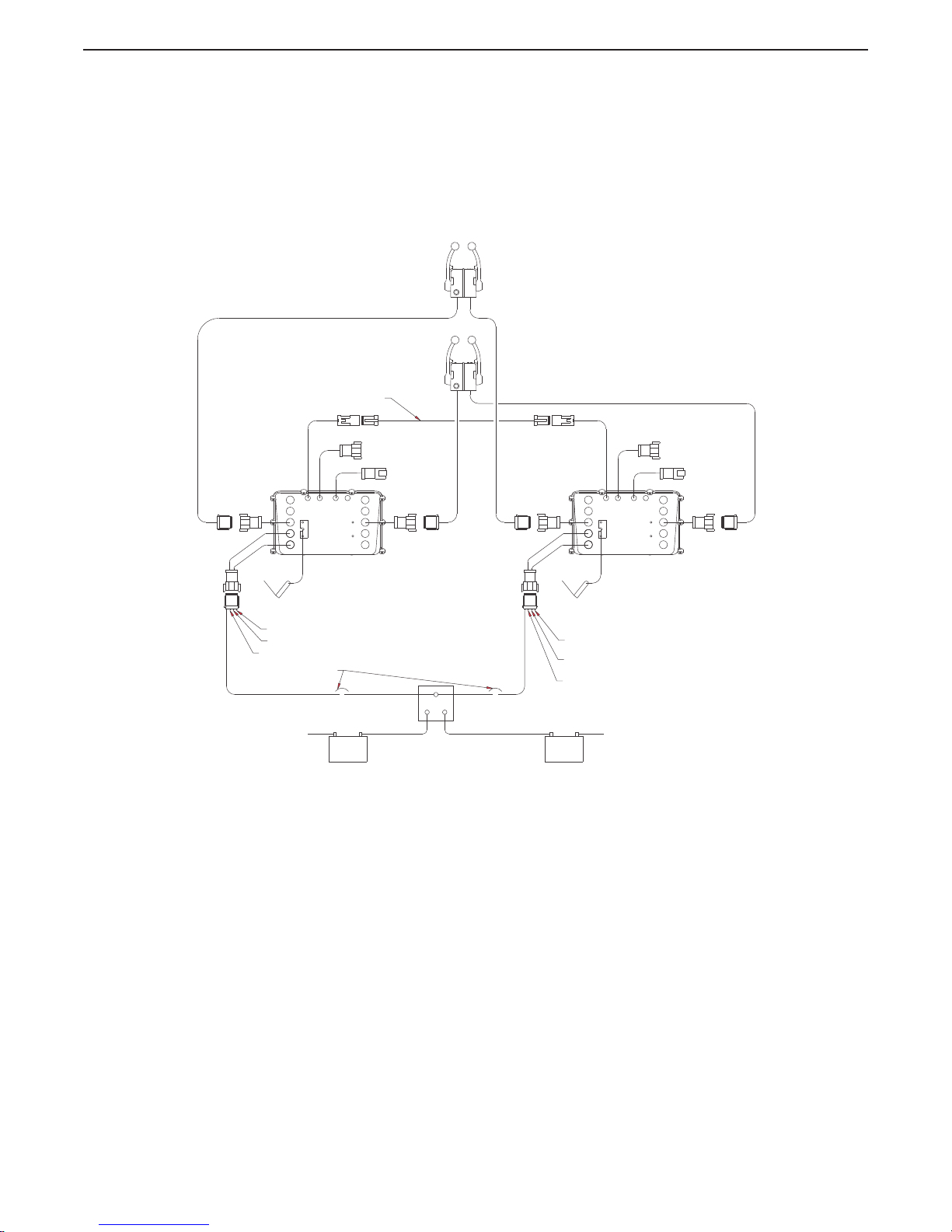
Figure 1-4: Basic 9211 ClearCommand System Diagram
33C PUSH/PULL CABLE
33C PUSH/PULL CABLE
TROLLSHIFT
F
N
RFR
N
TROLLSHIFT
STBD
STATION 2
STATION 1
PORT
12293-
SERIAL COMMUNICATION
10 AMP CIRCUIT BREAKERS
(BY OTHERS)
COMMON
GROUND
COMMON
GROUND
+
-
+
-
APS
CLUTCH PRES.
START INTERLOCK
ALARM
START INTERLOCK
CLUTCH PRES.
ALARM
TACH 1 TACH 1
THROTTLETHROTTLE
MIN
SLIP
MAX
SLIP
MIN
SLIP
MAX
SLIP
Page 26
26 EN 3340.758.003a - 2014-11
INTRODUCTION
MM9000 ClearCommand User Manual
Introduction
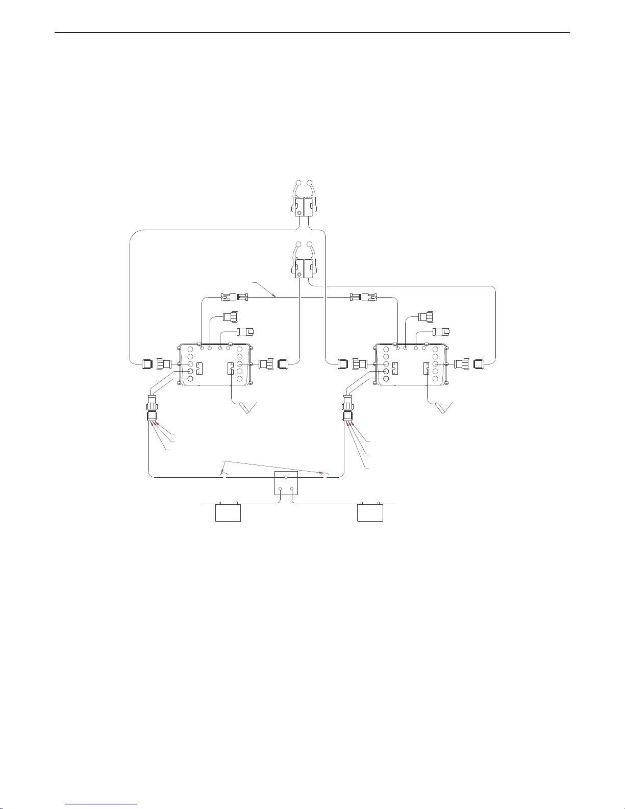
1.1.5 9221 Processor (Throttle - Electronic, Shift - Solenoid, Troll - Servo 2)
The 9221 System is designed for pleasure and light commercial marine vessels that require remote
control of:
• electronic engine governors
• solenoid activated clutches
• mechanically actuated trolling valves
The Processor is typically mounted in the engine room area and is connected to the electronic
governor with a two-conductor, shielded, electric cable.
The transmission’s Ahead and Astern solenoids are connected via 2 two-conductor cables, and the
trolling valve is controlled mechanically using a standard 33C type push-pull cable.
Figure 1-5: Basic 9221 ClearCommand System Diagram
1.2 System Features
1.2.1 Standard Features
• Station-in-Command indication. (Section 2.2: Taking Command)
• Up to five Remote Stations. (Section 2.2: Taking Command)
• Single Control Head lever command of speed and direction. (Section 2.3: Basic Operation)
33C PUSH/PULL CABLE
STBD
STATION 2
STATION 1
PORT
12297
SERIAL COMMUNICATION
10 AMP CIRCUIT BREAKERS
(BY OTHERS)
COMMON
GROUND
COMMON
GROUND
+
-
+
-
APS
CLUTCH PRES.
START INTERLOCK
ALARM
START INTERLOCK
CLUTCH PRES.
ALARM
TACH 1 TACH 1
THROTTLETHROTTLE
TROLL
MAX
SLIP
MIN
SLIP
TROLL
33C PUSH/PULL CABLE
MAX
SLIP
MIN
SLIP
Page 27
27
EN 3340.758.003a - 2014-11
OPERATION
MM9000 ClearCommand User Manual
Operation
2 Operation
2.1 DC Power On
When DC power is turned ON to the Processor:
• A short steady tone, followed by an intermittent tone, will sound at all Remote Stations indicating that
no station has command.
• The Start Interlock relay contact will remain open, preventing engine start.
• Throttle:
Servo:
The throttle servo will drive to Idle.
Electric:
The throttle signal will be commanded to Idle.
• Shift:
Servo:
The Shift servo will drive to Neutral.
Solenoid:
The Ahead and Astern shift solenoids will be de-energized, commanding Neutral.
• Tro ll:
Servo:
The trolling valve servo will drive to lock-up.
Solenoid:
The trolling valve solenoids are commanding lock-up.
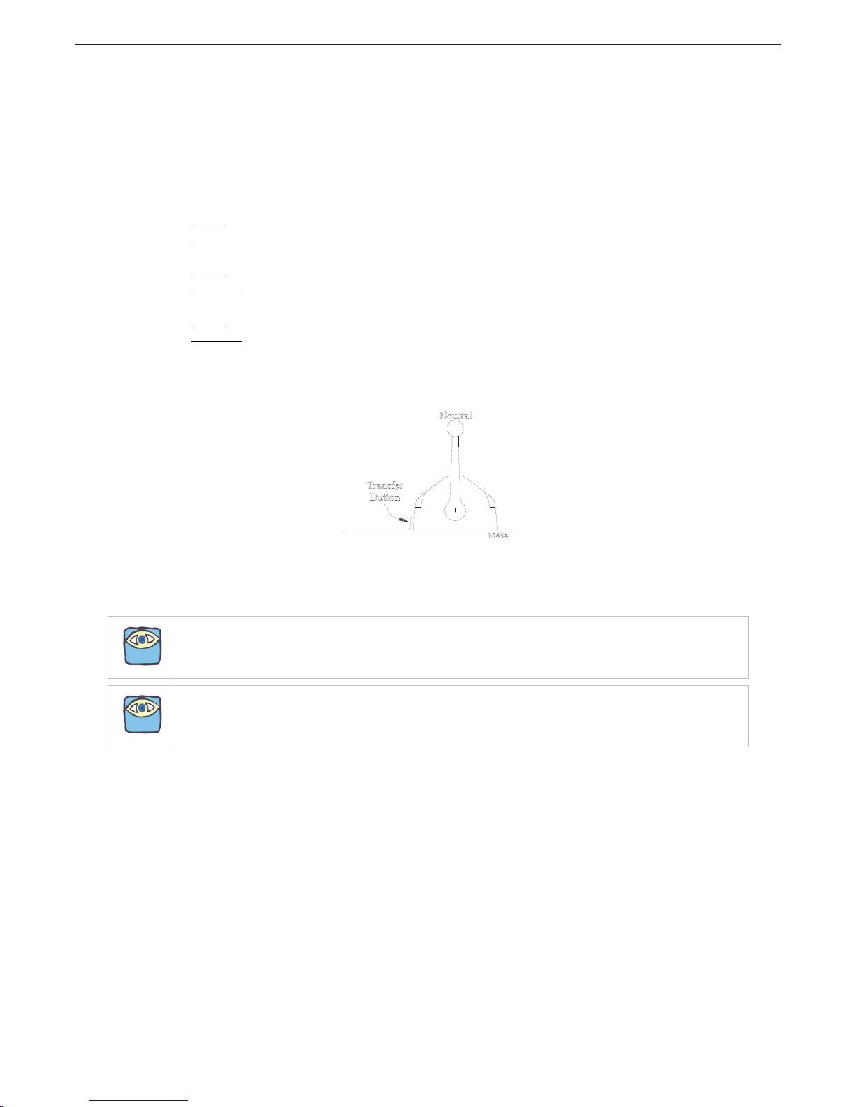
2.2 Taking Command
To take command at any one of the up to five Remote Stations:
• Ensure all Control Head’s lever(s) at that Station are in the Neutral detent (vertical position)
Figure 2-1: Station taking Command
• Depress the transfer button for 1/2 second.
The Slow Repetitive tone will stop at all Stations, and the red LED indicator light will turn ON at the Control
Head of the Station that had assumed command of the Control System.
NOTE: If Start Interlock is used: Once a Station is in command the Start Interlock relay contact will close,
allowing the engine to start.
NOTE: Only one Station can have command at a time.
Neutral
Transfer
Button
10454
Page 28
28 EN 3340.758.003a - 2014-11
OPERATION
MM9000 ClearCommand User Manual
Operation
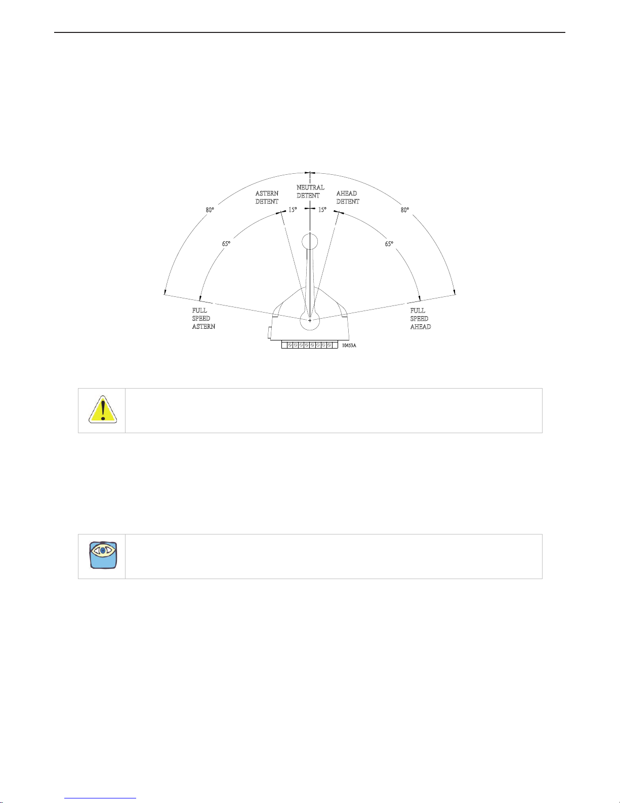
2.3 Basic Operation
2.3.1 Normal Operating Mode
A The Control Head has three detents; Ahead, Astern and Neutral.
B With the Control Head lever positioned in the Neutral (vertical) detent, the Processor will
command Neutral and the throttle at Idle revolutions per minute (RPM).
C Movement of the Control Head’s lever 15 degrees to the Ahead or Astern detent will
command Ahead or Astern clutch engagement, while the engine RPM remains at Idle.
D Further movement of the Control Head lever through the next 65 degrees, will increase the
engine RPM in proportion to the Control Head’s lever position.
Figure 2-2: Control Head Detents
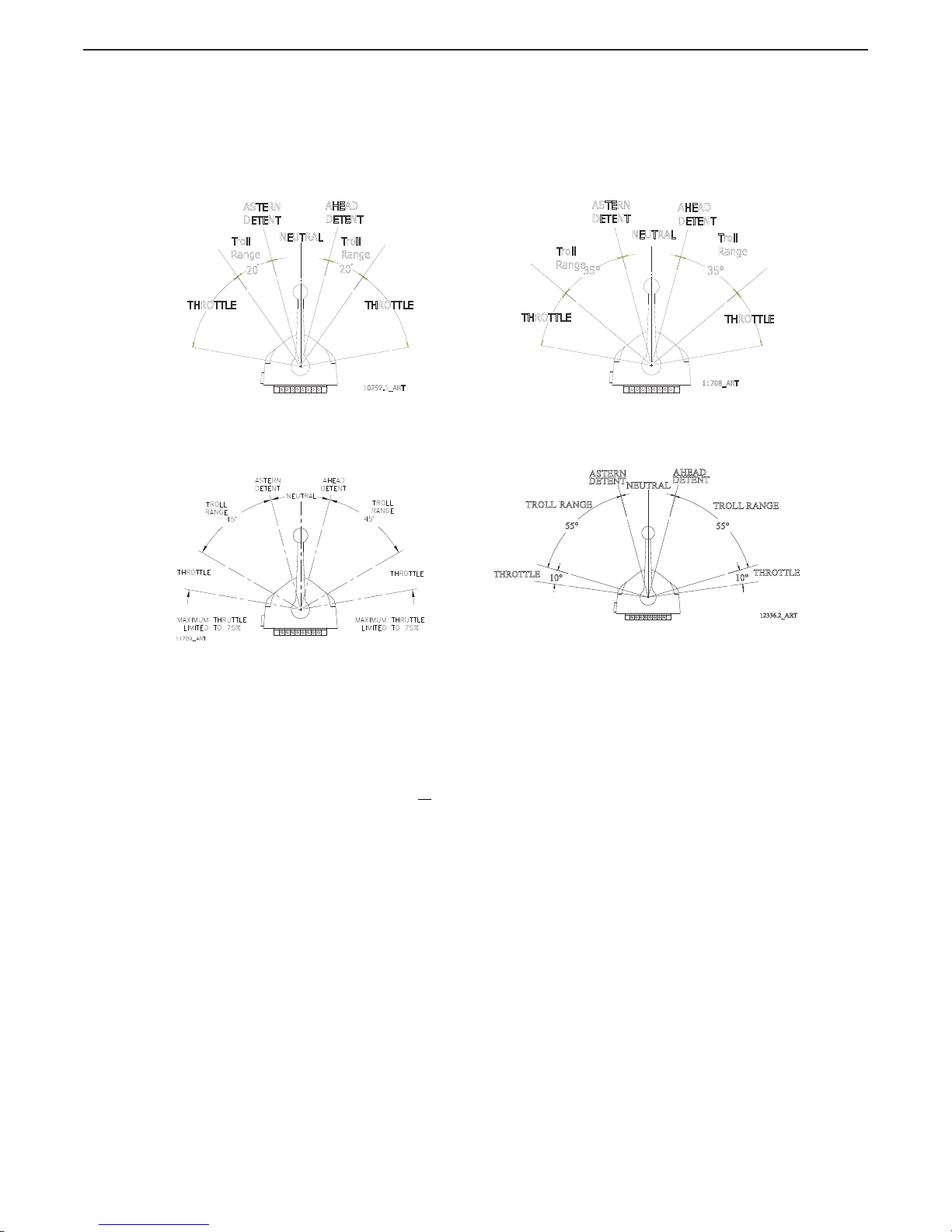
2.3.2 Trolling Valve Operation
The operation is quite different in Systems equipped with Trolling Valves. Troll Mode is a feature that
must be turned On and Off at the Control Head. On initial power-up, Troll Mode is disabled.
A The Control Head has three detents; Ahead, Astern and Neutral. To turn ON Troll Mode, place
the Control Head lever in any of the above mentioned detents.
• With the Control Head lever positioned in the Neutral (vertical) detent, the Processor will
command Neutral, the trolling valve will be at lock-up and the throttle at Idle rpm.
B Depress and hold the transfer button for two (2) seconds.
• The solid red indicator light on the Control Head will begin blinking rapidly, indicating the
system is now in Troll Mode.
C Once the system has been placed in Troll Mode, movement of the Control Head’s lever 15
degrees to the Ahead or Astern detent will command Ahead or Astern clutch engagement
and the trolling valve commanded to minimum pressure, while the engine RPM remains at
Idle.
WARNING: Personal Injury may result if this message is disregarded.
NOTE: If system is set for Twin Screw operation, ensure all Control Head levers are in the same detent
(Neutral, Ahead or Astern).
AHEAD
DETENT
ASTERN
DETENT
10453A
FULL
SPEED
ASTERN
FULL
SPEED
AHEAD
65°
65°
15°15°
NEUTRAL
DETENT
80°
80°
Page 29
29
EN 3340.758.003a - 2014-11
OPERATION
MM9000 ClearCommand User Manual
Operation
D Further movement through the selectable 25, 35, 45, or 55 degrees, will increase the clutch
pressure to maximum while the throttle remains at Idle.
E Further movement through the next 40, 30, 20, or 10 degrees will increase throttle to full,
except when 45 degrees is selected (where throttle is limited to 75% of full) and 55 degrees
is selected (where throttle is limited to 10% of full).
F To turn Troll Mode OFF, place the Station-in-Command into a detent (Neutral, Ahead, or
Astern).
G Depress and hold the Transfer Button until the red indicator light on the Control Head
becomes lit steady (approximately 2 seconds) then release the button. When the red indicator
light is a steady red, Troll Mode is disabled.
2.4 Start Interlock (if used)
The engine start signal is blocked unless all of the following are true:
• DC power has been turned ON to the Control System.
(Reference Section 2.1: DC Power On)
• A Remote Station is in command. (Reference Section 2.2: Taking Command)
• The Control System is commanding Neutral.
Figure 2-3: Control Head 20 Degree Troll Range - Type 1 Figure 2-4: Control Head 35 Degree Troll Range - Type 2
Figure 2-5: Control Head 45 Degree Troll Range - Type 3
Figure 2-6: Control Head 55 Degree Troll Range - Type 4
AHEAD
DETENT
Troll
Range
ASTERN
DETENT
Troll
Range
10292.1_ART
THROTTLE
20
NEUTRAL
20
THROTTLE
AHEAD
DETENT
Troll
Range
ASTERN
DETENT
Troll
Range
THROTTLE
NEUTRAL
THROTTLE
11708_ART
35°
35°
DETENT
AHEAD
DETENT
ASTERN
12336.2_ART
RANGE
TROLL
RANGE
TROLL
55°
NEUTRAL
55°
10°
10°
THROTTLE
THROTTLE
Page 30
30 EN 3340.758.003a - 2014-11
OPERATION
MM9000 ClearCommand User Manual
Operation
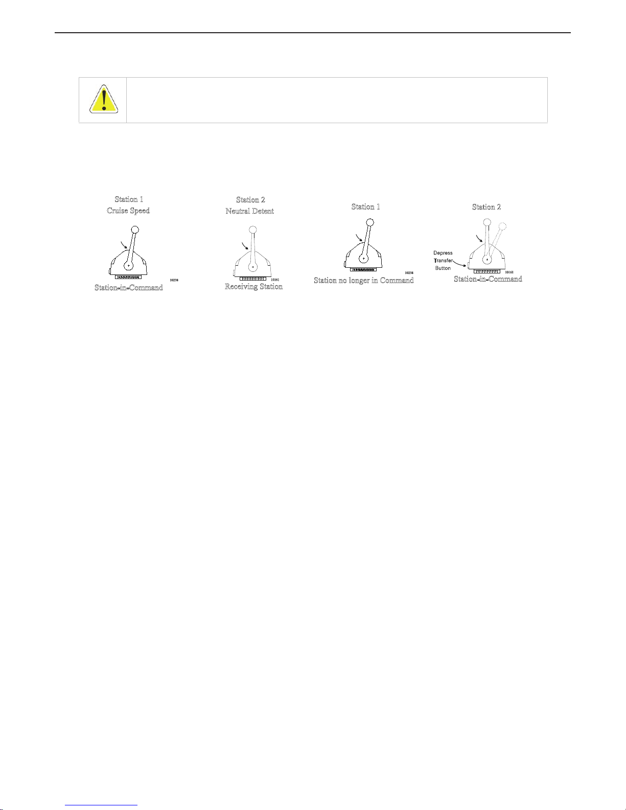
2.5 Station Transfer
Command can be transferred as follows:
A The Station-in-Command’s lever(s) may be left in any position.
B Place the Control Head’s lever(s) of the receiving Station in the Neutral/Idle detent position (refer to
Figure 2-7: Remote Stations Before Transfer of Command)
C At the Station taking command (Receiving Station), depress and hold the transfer button for 1/2
second (refer to Figure 2-8: Remote Station Transfer after Transfer of Command).
• The red LED indicator light at the receiving Station’s Control Head will illuminate, indicating
that the Station has taken command.
• The red LED indicator light will go OFF at the transferring Station’s Control Head, indicating
that the Station no longer is in command.
D The commanded positions of the Throttle and Clutch will remain unchanged for one second after the
red LED lights. This allows the operator time to move the Control Head’s lever(s) to a position
approximately matching the last Station, which will allow the vessel to maintain present speed and
direction.
2.6 Proportional Pause
The proportional pause provides a means of safely reversing the vessel’s direction. A variable pause is
introduced into the clutch command signal to allow time for the engine RPM’s to drop to Idle and for the
vessel’s speed through the water to slow. This pause is set during Section 7: Sea Trials.
WARNING: Personal Injury may result if this message is disregarded.
Figure 2-7: Remote Stations Before Transfer of Command Figure 2-8: Remote Station Transfer after Transfer of
Command
10238
Station-in-Command
Red Indicator
Light “on”
Station 1
Cruise Speed
10161
Receiving Station
Station 2
Red Indicator
Light “off”
Neutral Detent
10238
Station no longer in Command
Red Indicator
Light “off”
Station 1
10161
Station-in-Command
Depress
Transfer
Button
Station 2
Red Indicator
Light “on”
Page 31

31
EN 3340.758.003a - 2014-11
OPERATION
MM9000 ClearCommand User Manual
Operation
2.7 Warm-up Mode
This feature allows the operator to increase the engine’s RPM, while the Clutch remains in Neutral. Warm-Up
Mode is operational only when the Control Head lever is moved in the Ahead direction.
The system is placed into Warm-Up Mode as follows:
A At the Station-in-Command, ensure that the Control Head’s lever is in the Neutral detent position
(refer to Figure 2-9: Control Head Warm-Up Mode).
Figure 2-9: Control Head Warm-Up Mode
B Depress and hold the transfer button.
C After one second, move the Control Head’s lever to the Ahead detent, while continuing to hold the
transfer button.
D Now release the transfer button.
• The red LED indicator light will blink slowly, indicating Warm-Up Mode is activated and the
Clutch has remained at Neutral.
E The operator can start the engine, if required, and increase the RPM through the entire throttle range
by moving the Control Head’s lever forward through the next 65 degrees.
F When the Control Head’s lever is returned to the Neutral detent, the red LED will discontinue blinking
and remain lit steady. After one second in Neutral, the Processor will automatically reset to normal
operation with full control of the clutches and engine.
G The next movement of the Control Head’s lever will engage the Ahead or Astern clutch (Normal
Operation).
Figure 2-10: Control Head Normal Operating Mode
WARNING: Personal Injury may result if this message is disregarded.
Page 32

32 EN 3340.758.003a - 2014-11
OPERATION
MM9000 ClearCommand User Manual
Operation
2.8 High/Low Idle
The Control System provides the input to the engine, so that it may run at the standard Idle speed (typically
adjusted at the governor or carburetor), or it can provide a second elevated Idle speed.
2.8.1 Low Idle
• The factory default setting is for Low Idle Only.
• When the System is initially powered-up, it will always command Low Idle, even when High
Idle is selected.
2.8.2 High Idle
• If High Idle is desired, it may be programmed during Dock Trials.
• High Idle is programmable up to a maximum setting of 20% of Full Throttle.
• High Idle is automatically selected when in Warm-Up Mode.
2.8.3 Selecting Between High and Low Idle
Refer to Figure 2-11: High/Low Idle Mode Selection when selecting between Low and High Idle (or
vice versa) at the Station-in-Command
Figure 2-11: High/Low Idle Mode Selection
A The Control Head’s lever(s) may be in the Neutral, Ahead or Astern detents when making a
selection.
B Depress and hold the transfer button for 1/2 second and then release.
• If the System was in Low Idle it will toggle to High Idle, and vice versa.
C To return to the previous Idle setting, depress and hold the transfer button again for 1/2
second and then release.
WARNING: Personal Injury may result if this message is disregarded.
NOTE: In Twin Screw applications, always program both Processors for the same amount of High Idle. In Twin
Screw applications, both the Port and Starboard Processors will always be in High or Low Idle at the same
time.
Depress and Hold Transfer Button
for ½ second to toggle between
High and Low Idle
10238
Control Head
levers may be
in Neutral, Ahead,
or Astern Detent
Page 33

33
EN 3340.758.003a - 2014-11
OPERATION
MM9000 ClearCommand User Manual
Operation
2.9 One Lever Mode (Twin Screw)
The system supports a mode of operation referred to as One Lever Mode, which allows the operator to
control both engines and transmissions with a single Control Head lever. The Port or the Starboard lever at
any Remote Station can be designated by the operator as the Master lever. The designation can be changed
by the operator at any time. Most of the features (synchronization, troll, etc.) available in normal operation are
available while operating in One Lever Mode.
• The Processor defaults to One Lever Mode disabled.
• One Lever Mode can be disabled or enabled in the Set Up Procedures.
• When One Lever Mode is enabled, the operation must be turned ON and OFF as described below.
2.9.1 Turning ON One Lever Operation
A At the Station-in-Command, move the Port and Starboard Control Head levers to the Ahead
detent.
B Depress and Hold
the transfer button while moving the Port or Starboard Control Head’s lever
out of the Ahead detent. Do Not Release the Transfer Button until the green LED turns ON,
indicating One Lever Operation is now active.
Figure 2-12: Step A) One Lever Operation Mode
• The Control Head lever which the operator chose to move out of the Ahead detent, becomes
the Master lever.
NOTE: One Lever Operation may be used in Troll Mode or in Non-Troll Mode.
NOTE: The Green LED will always be lit while in One Lever Operation, no matter what position the Master
Control Head lever is in.
WARNING: Personal Injury may result if this message is disregarded.
Page 34

34 EN 3340.758.003a - 2014-11
OPERATION
MM9000 ClearCommand User Manual
Operation
• The Control Head lever which was left in the Ahead detent is now inactive.
Figure 2-13: Step B) One Lever Operation Mode
2.9.2 Turning OFF One Lever Operation
A Place the Master lever into the Neutral detent.
B Place the inactive Control Head lever into the Neutral detent.
• Whenever the inactive lever is moved to the Neutral detent, One Lever operation is turned
OFF. The green LED will turn OFF, indicating that the control system is now in normal
operating mode.
NOTE: The Control Head lever designated by the operator to be inactive in One Lever Operation, may be left in
the Ahead detent or moved fully forward. Moving the lever fully forward is recommended, because it moves it
out of the way and prevents accidental bumps while operating.
WARNING: It is strongly recommended that the Master lever is returned to the Neutral/Idle position prior to
turning OFF One Lever Operation.
Do not attempt to transfer command from one Remote Station to another while in One Lever Operation.
Always turn One Lever Operation OFF prior to transferring.
Failure to observe these recommendations may result in a sudden change in the vessel’s direction.
Page 35

35
EN 3340.758.003a - 2014-11
OPERATION
MM9000 ClearCommand User Manual
Operation
2.10 Engine Synchronization (Twin Screw)
Engine Synchronization must be selected during Set Up to have automatic synchronization.
Synchronization is automatic and only operates when the Ahead clutch is engaged, consequently it can be
left ON full time. When synchronization has been selected during set up, the Control System will always
power-up with synchronization ON.
In order for synchronization to become active and work toward synchronizing the engines' RPM's, the
Synchronization Criteria listed below must be met.
2.10.1 Synchronization Criteria
• Both Control Heads must be commanding 5% or greater of the throttle range.
• The Control Head levers must be within 10% of one another (+/- approximately 6 degrees).
• Both Control Head levers are commanding Ahead clutch engagement.
2.10.2 Synchronization Types
The following types of synchronization use the same criteria, indications, and are turned ON and OFF
as described in following Sections.
2.10.2.1 Equal Throttle Synchronization (Twin Screw) (default)
Equal Throttle synchronization simply commands the same throttle to both engines (i.e. push-pull
cables travel the same distance; electronic signals are the same). With Equal Throttle Synchronization
the Processors do not
receive tachometer signals representative of the engines RPM's.
NOTE: The Control System offers two types of synchronization, Active or Equal Throttle.
NOTE: The use of Value 03 for Function Code E7 should be avoided in the 9000 Series Processors with
mechanical throttle control.
Symptom
:
When selected, Value 03 (Active Synchronization, no Synch if Tach signal lost) for Function Code E7
(Synchronization) may give the operator the appearance that synchronization is not functioning. This is due to
the fact that the Control Head’s green Synch indication LED does not light until both engine RPM’s are within
the “Active Synch Deadband”. “Active Synch Deadband” is the maximum allowable difference in engine RPM,
where the Processors consider the system synchronized adequately. Once obtained, the control system does
not attempt to match
the RPM’s any closer.
When in this Mode of Operation, there is no indication to the operator that the Control Head levers are
matched close enough to start the synchronization process. Additionally, the green indication LED does not
blink while working toward synchronization.
Cause
:
Function Code E7, Value 03, is operating as designed. Due to the imprecise positioning of mechanical pushpull cables, the ability to position the cables within the “Active Synch Deadband” is severely impaired.
Solution
:
All Processors with mechanical throttle control, where synchronization is desired, must set the Value of
Function Code E7 to Value 01 (Active Synchronization reverts to Equal Throttle Synchronization if Tach Signal is
lost)
CAUTION: The Control System will remain synchronized as long as the Control Head's levers are in close
proximity to one another. If a lever is moved to a point where the 10% throttle window is exceeded, a 10%
increase or decrease in engine RPM would occur with one engine, resulting in a sudden change in the vessel's
direction.
Page 36

36 EN 3340.758.003a - 2014-11
OPERATION
MM9000 ClearCommand User Manual
Operation
2.10.2.2 Active Synchronization (Twin Screw) (default Disabled)
Active Synchronization must be enabled during Set Up and a Tach Sensor Wire Harness must be used.
The Processors each receive a tachometer signal representing engine RPM from their respective
engines. These signals are compared with one another over a serial communication line. If the
Synchronization Criteria is met, the throttle command signal of the engine running at the higher RPM is
lowered, until the RPM's of both engines match.
2.10.3 Synchronization Indications
The green LED located on the Control Head indicates the status of synchronization.
• In Active Synchronization the green LED blinks every time there is a change in the
commanded throttle.
• When the green LED is lit steady, the engines are synchronized.
• When the green LED is not lit, the engines are not synchronized and the Control System is not
attempting to do so.
2.10.4 Turning Synchronization OFF:
A Ensure that the Control Head's levers are positioned to a point where Synchronization Criteria
are met.
B Press and hold the transfer button until the green LED blinks twice and then goes out
(approximately 2 seconds).
C Synchronization is now OFF.
2.10.5 Turning Synchronization ON:
A Ensure that the Control Head's levers are positioned to a point where Synchronization Criteria
are met.
B Press and hold the transfer button until the green LED lights (approximately 2 seconds).
• The green LED will blink as the system is working toward synchronization.
• The green LED will become solid when the engines are synchronized.
2.10.6 Turning Synchronization ON and OFF when Control Head Levers are not within a 10% (6
degree) Window of One Another:
The actual synchronizing of the engines occurs when the Control Head levers are within the 10%
(approximately 6 degrees) window of one another. However, synchronization can be turned ON or
OFF when the Control Head levers are apart more than the 10% (approximately 6 degrees) window of
one another.
• When synchronization is turned ON by pressing the transfer button, the green LED will light
after two seconds and stay lighted as long as the transfer button is depressed.
• When turning OFF synchronization by pressing the transfer button for two seconds, the green
LED will blink twice indicating that synchronization is turned OFF.
NOTE: In order for Equal Throttle Synchronization to work properly in Systems with mechanical Throttles, the
bends in the push-pull cables must be kept to a minimum. There can be no back-lash in the linkage or cables.
Both Governors or Carburetors must provide equal engine RPM with equal movement of their selector levers. If
these conditions can not be met, Active Synchronization is recommended.
Page 37

37
EN 3340.758.003a - 2014-11
OPERATION
MM9000 ClearCommand User Manual
Operation
2.11 Control System’s Configurability
The Processor is designed in a way which allows it to be easily configured by the installer to meet the varying
needs of a wide variety of vessels. Below you will find a list and a brief description of the groups of these
functions.
2.11.1 Processor Functions
Within this section of adjustable parameters, there are up to five different adjustments:
• A0 Processor Identification
- Assigns each Processor in multi-screw application a unique
identifying number. This function must be the second function set during Set Up.
• A1 Number of Engines
- Lets the Processor know how many other Processors need to be
communicated with. This function must be the first function set during Set Up.
• A2 One Lever Operation
- Allows the installer to disable or enable One Lever Mode capability.
• A3 Station Expander
- Allows the Processor to communicate with the Station Expander (SE).
• A4 Neutral Indication Tone
- When turned ON, produces a short 200 Hz tone to indicate
Neutral.
Detail information on each function is found in Section 5.7.3.1: Basic Processor Troubleshooting
Functions.
2.11.2 Throttle Functions
2.11.2.1 Basic Throttle Functions
This section applicable to both electronic and servo Throttle adjustment:
• E1 Throttle in Neutral
- Adjusts the position of the Throttle while in Neutral
• E5 Throttle Pause following Shift
- Allows a pause prior to applying speed above Idle.
• E6 High Idle
- Programs a second elevated Idle RPM.
• E7 Synchronization
- Allows the installer to select synchronization and select the type of
synchronization.
Detail information on each function is found in Section 5.6.2.1: Throttle Basic Functions.
2.11.2.2 Servo Throttle Functions
This section along with Section 2.11.2.1: Basic Throttle Functions allows the adjustment of the Servo
Throttle:
• E0 Engine Throttle Profile
- Select whether the Throttle Servo pushes or pulls to increase
speed.
• E2 Throttle Minimum
- Once set mechanically at the Idle stop, this Function Code allows the
position of the push-pull cable to be adjusted electrically in order to eliminate “dead lever”.
Dead lever in this case can be described as a movement of the Control Head lever without a
change in the engine’s RPM.
• E3 Throttle Maximum
- Adjusts the position or amount of travel of the push-pull cable at Full
Throttle.
• E4 Throttle Maximum Astern
- Limits the amount of the Astern Throttle Servo movement.
Detail information on each function is found in Section 5.7.0.1: Throttle Servo Functions.
2.11.2.3 Electronic Throttle Functions
This section along with Section 2.11.2.1: Basic Throttle Functions allows the adjustment of the
Electronic Throttle:
• E0 Engine Throttle Profile
- Selects the type of Throttle Command signal.
• E2 Throttle Minimum
- Adjusts the Throttle Command signal at Idle.
• E3 Throttle Maximum
- Adjusts the Throttle Command signal at Full Throttle.
• E4 Throttle Maximum Astern
- Limits the amount of the Astern Throttle Command signal.
Detail information on each function is found in Section 5.7.0.2: Throttle Electronic Functions.
Page 38

38 EN 3340.758.003a - 2014-11
OPERATION
MM9000 ClearCommand User Manual
Operation
2.11.3 Clutch Functions
2.11.3.1 Basic Clutch Functions
The following functions are available for all types of clutches.
• C0 Clutch Pressure Interlock -
Selects the Clutch Pressure Interlock option.
• C1 Clutch Interlock Delay -
Determines when the Clutch Pressure Interlock becomes active.
• C2 Proportional Pause -
Selects between an In-Gear, Neutral, or Fixed Neutral delay.
• C3 Proportional Pause Time -
Selects the maximum delay during a full speed reversal.
• C4 Proportional Pause Ratio -
Determines if the Ahead and Astern reversal times are the
same or if Astern is one half of Ahead.
Detail information on each function is found in Section 5.7.1: Clutch Functions.
2.11.3.2 Clutch Servo Functions
This section along with the Section 2.11.3.1: Basic Clutch Functions Section allows the adjustment of
Clutch servo related items:
• C5 Clutch Servo Direction -
Determines if the servo pushes or pulls for Ahead and Astern.
• C6 Clutch Ahead -
Adjusts the amount of clutch servo travel in Ahead.
• C7 Clutch Astern -
Adjusts the amount of clutch servo travel in Astern.
Detail information on each function is found in Section 5.7.1.2: Clutch Servo Functions.
2.11.3.3 Clutch Solenoid Functions
This section along with the Basic Clutch Functions Section allows the adjustment of Clutch Solenoid
related items:
• C5 Shift Solenoid Type -
Selects the approximate current levels for the 12 or 24 VDC ZF
Hurth Solenoids.
• C6 ZF-Hurth Duty Cycle Ahead -
Fine tunes the maximum current level to the Ahead
Proportional Solenoid.
• C7 ZF-Hurth Duty Cycle Astern -
Fine tunes the maximum current lever to the Astern
Proportional Solenoid.
Detail information on each function is found in Section 5.7.1.3: Clutch Solenoid Functions.
2.11.4 Troll Functions
2.11.4.1 Basic Troll Functions (All Processors with Troll Function)
The following functions are available for all Processors with the option of Trolling Valve Control feature.
• L4 Troll Throttle Limit
- Allows an increase in Throttle while slipping the Clutch.
• L5 Troll Pulse Duration
- Selects the amount of time for Troll Pulse Percentage.
• L6 Troll Pulse Percentage
- Selects the percentage of Troll Minimum when first engaging the
Clutch with Troll.
Detail information on each function is found in Section 5.7.2: Troll Functions.
2.11.4.2 Troll Servo Functions
This section, along with the Basic Troll Functions Section allows the adjustment of servo Trolling Valve
related items:
• L0 Troll Enable and Control Head Lever Range
- Turns Troll ON (Integrated) and sets the
degrees of Control Head lever movement dedicated to Troll.
• L1 Troll Servo Direction
- Determines if the Troll push-pull cable is retracted or extended at
Lock-up.
• L2 Troll Minimum Pressure
- Adjusts the Troll push-pull cables position at minimum Shaft
rotation.
• L3 Troll Maximum Pressure
- Adjusts the Troll push-pull cable’s position at maximum Shaft
rotation (not maximum pressure).
Detail information on each function is found in Section 5.7.2: Troll Functions.
NOTE: The following Troll Functions are available for the 9001 Troll Actuator or Integrated Servo Troll
command.
Page 39

39
EN 3340.758.003a - 2014-11
OPERATION
MM9000 ClearCommand User Manual
Operation
2.11.4.3 Integrated Troll Solenoid Functions
This section, along with the Basic Troll Functions Section, allows the adjustment of solenoid Trolling
Valve related items:
• L0 Troll Enable and Control Head Lever Range
-Turns Troll ON and sets the degrees of
Control Head lever movement dedicated to Troll.
• L1 Troll Valve Function
- Selects the proper current range for a particular gear. This Function
must be the 3rd function set if ZF Hurth Gears are used.
• L2 Troll Minimum Pressure
- Adjusts the amount of current at minimum Shaft rotation.
• L3 Troll Maximum Pressure
- Adjusts the amount of current at maximum Shaft rotation (not
maximum pressure).
Detail information on each function is found in Section 5.7.2.1.2: Troll Solenoid L1 Function.
2.11.5 Troubleshooting Functions
2.11.5.1 Basic Troubleshooting Functions
• H0
Diagnostics - Allows the installer/technician to look at various inputs to the Processor.
• H1
Return to Factory Defaults - Returns all settings to the factory default values.
Detail information on this function is found in Section 5.7.2: Troll Functions.
2.11.5.2 Additional Troubleshooting Functions
• H2 Driver Fault Detection Enable
- Allows the Processor to monitor the clutch and/or troll
solenoids.
Detail information on this function is found in Section 5.7.2: Troll Functions.
2.12 Audible Tones
2.12.1 Basic Processor Tones
The Processor can produce numerous tones which inform the operator of the status of the system or
if any faults were to occur. These tones are emitted from all Remote Stations regardless of whether
they are in command or not.
2.12.1.1 Slow Repetitive Tone
Detail information on this tone is in Section 10: Troubleshooting.
This tone is normal when DC power is first applied to the System. This tone indicates that system
initialization has occurred, no Remote Station has command, the operator can accept command at any
Remote Station.
2.12.1.2 One Long, Three Short Tones
Detail information on this tone is in Section 10: Troubleshooting.
This tone indicates that the command signal from a Control Head’s potentiometer has gone out of
range.
2.12.1.3 Steady Tone
Detail information on this tone is in Section 10: Troubleshooting.
This tone indicates that the software program within the Processor has quit running, due to low voltage
or component failure.
2.12.1.4 Five (5) Second Steady Tone
Detail information on this tone is in Section 10: Troubleshooting.
This tone indicates that there has been a loss of Serial Communication.
2.12.1.5 Three (3) Second Steady Tone
Detail information on this tone is in Section 10: Troubleshooting.
This tone is heard if there is a stuck transfer button, or when entering Back-up Mode, or if a Troll
Solenoid error occurs. (Back-up Mode and Troll Solenoid is not available for all Processors.)
2.12.1.6 Five Seconds On, Five Seconds Off - High Repetitive Rate Tone
Detail information on this tone is in Section 10: Troubleshooting.
This tone indicates that Function Code A3 Station Expander (SE) has had the value 01 Enabled
entered, but the Processor and Station Expander cannot communicate.
Page 40

40 EN 3340.758.003a - 2014-11
OPERATION
MM9000 ClearCommand User Manual
Operation
2.12.2 Throttle (Servo 2) Tones
The following Tones are in addition to the Basic Processor Tones.
2.12.2.1 One Long - Two Short Tones
Detail information on this tone is in Section 10: Troubleshooting.
This tone indicates that the feedback potentiometer signal from Servo 2 (Throttle) has gone out of
range.
2.12.2.2 One Long, Two Short - High Repetitive Tone
Detail information on this tone is in Section 10: Troubleshooting.
This tone indicates that Servo 2 (Throttle) cannot reach the commanded position. This tone is also
referred to as Servo 2 Jam Tone.
2.12.3 Clutch (Servo 1) Tones
The following Tones are in addition to the Basic Tones listed in Section 2.12.1: Basic Processor Tones.
2.12.3.1 One Long - One Short Tone
Detail information on this tone is in Section 10: Troubleshooting.
This tone indicates that the feedback potentiometer signal from Servo 1 (Clutch) has gone out of range.
2.12.3.2 One Long, One Short -High Repetitive Rate Tone
Detail information on this tone is in Section 10: Troubleshooting.
This tone indicates that Servo 1 (Clutch) cannot reach the commanded position. This tone is also
referred to as Servo 1 Jam Tone.
2.12.4 Clutch Solenoid Tones
2.12.4.1 One Long - One Short Tone
Detail information on this tone is in Section 10: Troubleshooting.
This tone indicates that a fault was detected with either the Ahead or Astern Clutch Solenoid.
2.12.5 Troll Integrated Servo (Servo 1) Tones
The following Tones are in addition to the Basic Tones listed in Section 2.12.1: Basic Processor Tones.
2.12.5.1 One Long - One Short Tone
Detail information on this tone is in Section 10: Troubleshooting.
This tone indicates that the feedback potentiometer signal from Servo 1 (Troll) has gone out of range.
2.12.5.2 One Long, One Short -High Repetitive Rate Tone
Detail information on this tone is in Section 10: Troubleshooting.
This tone indicates that Servo 1 (Troll) cannot reach the commanded position. This tone is also referred
to as Servo 1 Jam Tone.
2.12.6 Troll Integrated (Servo 2) Tones
The following Tones are in addition to the Basic Tones listed in Section 2.12.1: Basic Processor Tones.
2.12.6.1 One Long - Two Short Tones
Detail information on this tone is in Section 10: Troubleshooting.
This tone indicates that the feedback potentiometer signal from Servo 2 (Troll) has gone out of range.
2.12.6.2 One Long, Two Short - High Repetitive Tone
Detail information on this tone is in Section 10: Troubleshooting.
This tone indicates that Servo 2 (Troll) cannot reach the commanded position. This tone is also referred
to as Servo 2 Jam Tone.
2.12.7 9001 Trolling Actuator Tones (Servo 3)
The following Tones are in addition to the Basic Tones listed in Section 2.12.1: Basic Processor Tones.
2.12.7.1 One Long, Four Short Tones
Detail information on this tone is in the Manual supplied with the 9001 Trolling Actuator.
This tone indicates that there is a feedback error in the Trolling Actuator.
Page 41

41
EN 3340.758.003a - 2014-11
OPERATION
MM9000 ClearCommand User Manual
Operation
2.12.7.2 One Long, Four Short - High Repetitive Rate Tone
Detail information on this tone is in the Manual supplied with the 9001 Trolling Actuator.
This tone indicates that Trolling Actuator Servo cannot reach the commanded position.
2.12.8 Troll Integrated Solenoid Tones
2.12.8.1 Three Second Steady Tone
This tone indicates that the Troll Solenoid is OPEN or shorted. Refer to the Error Code displayed for
further information.
2.13 Push Button Set Up
There are four push buttons mounted to the Processor’s circuit board. These push buttons allow the installer/
technician access to all of the Functions required for programming and troubleshooting the Processor.
A full description of their usage is provided in Section 5.1.2: Push Buttons.
2.14 Visual System Diagnostics, Set Up And Status Indication
There are four, seven segment LED’s (hereafter referred to as the Display LED) mounted to the Processor’s
circuit board. The Display LED is visible through a transparent window in the Processor’s cover. The
information displayed on the Display LED is used in conjunction with the push buttons to program the
Processor. The Display LED also displays Error Codes in the event that an anomaly is detected.
For a full description of the Display LED, its capability and usage, refer to Section 5.1.1: Processor Display
LED.
Figure 2-14: Circuit Board Shield Layout
Page 42

42 EN 3340.758.003a - 2014-11
OPERATION
MM9000 ClearCommand User Manual
Operation
2.15 Pluggable Connections
2.15.1 Standard Pluggable Processor
The standard Processor comes from the factory with five Pigtail Connectors for easy, mistake free
pluggable installations. Not all Processors are supplied with all of these pigtails.
The following is a list of the pigtail connectors used in the standard Processor:
• Tw o Remote Station pigtails. Three additional Stations can be connected directly to the
standard Processor.
• One pigtail connector provides the connections for DC Power, Start Interlock, Clutch Pressure
Interlock and External Alarm.
• One pigtail connector is provided for serial communication between multiple Processors.
• One pigtail connector is provided for the Tach Sensor input used in synchronization.
Figure 2-15: Standard Processor Pluggable Connections View
2.15.2 ClearCommand 9000 Series Pluggable Processors
The 9000 Series Processors come from the factory with standard five Pigtail Connectors listed in
Section 2.15.1: Standard Pluggable Processor and additional Pigtails depending on the Processor’s
features. Refer below to the Processor being used on this System for the list of additional pigtails.
9120 and 9121 Processors
• One pigtail connector is provided for clutch Ahead and Astern Solenoid signals.
9122 Processor
• One pigtail connector is provided for clutch Ahead and Astern Solenoid signals, the troll
solenoids.
9210 and 9211 Processors
• One pigtail connector is provided for electronic connection to the engine governor.
9221 Processor
• One pigtail connector is provided for electronic connection to the engine governor.
• One pigtail connector is provided for clutch Ahead and Astern Solenoid signals.
Station 4
Pigtail
Station 5
Pigtail
12239.2_ART
Digital Inputs
Tach 2 Pigtail
Tach 1 Pigtail
Serial Communication
Pigtail
Station 3
Pigtail
Alarm, Start Interlock,
Clutch Pressure Pigtail
Station 1
Pigtail
Station 2
Pigtail
Page 43

43
EN 3340.758.003a - 2014-11
OPERATION
MM9000 ClearCommand User Manual
Operation
2.16 Optional Features Operation
2.16.1 System Failure External Alarm
• This optional feature is designed to provide a status signal to an external alarm circuit.
• The status signal is in the form of an open or closed relay contact. When the contact is closed,
the Processor is functioning normally. When the contact opens, this indicates the software
program has quit running due to a component failure or loss of DC power.
• A full explanation is provided in Section 8.1: External Alarm Capability.
2.16.2 Clutch Pressure Interlock
• The purpose of the Clutch Pressure Interlock is to prevent high engine RPM when the Clutch is
not fully engaged.
• A full explanation of the Clutch Pressure Interlock is provided in Section 8.2: Clutch Pressure
Interlock.
2.16.3 Station Expander (SE)
• The SE is a separate Processor housed in an enclosure that allows the connection of up to five
additional Remote Control Stations.
• The SE communicates with the Processor over the serial communication line.
• A full explanation of the installation, operation and adjustment of the SE is provided in the
Installation Manual provided with the SE.
• Additional information can be found in Section 8.3: Station Expander (SE).
2.16.4 Multiple Screw Installations
This Manual, as written, is intended for Single and Twin Screw applications only.
The Processor has the capability of controlling Triple, Quad and Quint Screw vessels. In order to do
so, contact your ZF Marine Propulsion Systems Miramar, LLC representative for the required
information and materials.
2.16.5 9001 Mechanically Actuated Trolling Valve Control
• The purpose of a Trolling Valve is to lower the Clutch pressure, which allows the Clutch Plate
to slip.
• A full explanation is provided in the Installation Manual provided with the 9001 Trolling
Actuator.
• Further information on Trolling Valve Control can be found in Section 8.4: 9001 Actuator
Trolling Valve Control.
Page 44

44 EN 3340.758.003a - 2014-11
Page 45

45
EN 3340.758.003a - 2014-11
PLAN THE INSTALLATION
MM9000 ClearCommand User Manual
Plan the Installation
3 Plan the Installation
3.1 System Requirements
The first step when installing a System is to carefully plan the installation. This includes finding proper
mounting locations for the Processor(s) and Control Heads. The decision must be made on where power is
going to be sourced and how the power will be routed to the Processor(s). Once the locations have been
decided, lengths of electrical wiring, Harnesses and push-pull cables must be determined.
Figure 3-1: Processor Dimensions
• Bonding is required for maximum electromagnetic compatibility (EMC) performance. Refer to MMC287 Grounding (Bonding).
• Locate the Processor such that the push-pull cables have the shortest, most direct path to the selector
lever. The push-pull cable length should not excee d 20 feet (6,0m), the bend radius should not be less
than 10 inches (254mm) and the total degrees of bends must be less than 270 degrees.
Only when the previous items have been completed, should you start the actual installation. The following
sections describe the requirements for installing the components and selecting mounting locations.
3.1.1 Processor(s)
Processors required per engine:
• Single Screw: One (1) Processor
• Twin Screw: Two (2) Processors
Mounting Hardware is installer supplied.
Installation/Troubleshooting Manual is included with the Processor.
The following items must be taken into account when selecting the location for the Processor(s):
• The Processor is spray proof, but not water proof. Therefore, an area must be selected that
typically stays dry.
• The engine room is the preferred location for mounting the Processor.
• If the engine room is too small, locate in any area where it is easily accessible, as long as all of
the criteria listed are met.
• Bulkhead mounting is the preferred method due to ease of access for wiring and adjustments.
However, the Processor can be mounted in any attitude as long as the Display LED window
and push buttons are accessible.
NOTE: ZF Marine Propulsion Systems Miramar, LLC recommends that the system be installed in accordance
with ABYC, E-11 and P24.
4.75
(120,7mm)
3.20
(81,3mm)
10.25
(260,4mm)
10.40
(264,2mm)
6.70
(170,2mm)
2.69
(68,3mm)
10.71
(272mm)
2.70
(68,6mm)
12256-
WARNING: Note that the dimensions are out of scale, pay attention to properly size the cut out before use !
Page 46

46 EN 3340.758.003a - 2014-11
PLAN THE INSTALLATION
MM9000 ClearCommand User Manual
Plan the Installation
• Do not mount the Processor on the engine, transmission, or in any location that will subject it
to excessive vibration.
• Do not
mount the Processor to the transom when the vessel is equipped with a surface
piercing drive system, due to vibration concerns.
• Locate the Processor(s) away from sources of high heat, such as an engine exhaust manifolds
or turbochargers. Allow 4 feet (1,2m) of clearance or more.
• Do not
mount the Processor(s) in close proximity to gas engine ignition systems, alternators,
generators or any equipment producing strong magnetic fields. Allow 4 feet (1,2m) clearance
or more.
3.1.2 Control Head(s)
Refer to
MMC-280 400 Series Control Head Variations for information on the various Control Heads
available and their dimensions.
• The 400 and MC2000 Series Control Heads are spray proof from the top, but must be
protected from the weather on the underside.
• The 700 Series Control Heads are fully water proof.
• Control Heads are available with pluggable pigtails or may be hard-wired (no pigtails).
• When a 400 or MC2000 Series Control Head must be mounted in a location where the
underside may be exposed to the weather, consider using a Weather Mount Enclosure. Refer
to the MMC-279 400 Series Weather Mount Enclosure for specific information.
• Ensure that the clearance is sufficient for the Control Head’s lever to reach full Ahead and full
Astern.
• Retrofit applications may require an Adapter Pad to cover the old Control Head cutout. A
variety of Adapters and Cover Pads are available. Refer to MMC-288 References and Parts
Source for details.
• The Control Head can be mounted at any location on the vessel, as long as all of the criteria
listed above are met.
3.1.3 Standard Wire Harnesses
(Refer to the
MMC-288 References and Parts Source)
The following lists the various Harnesses that plug into the Standard Processor:
3.1.3.1 Control Head Harnesses
• One Control Head Harness is required for every Control Head lever at every Remote Station.
• The Control Head Harnesses are available in various lengths.
• Harnesses are available with plugs on both ends or a plug on the Processor side only.
• The Harness from the Port side of a Control Head is always routed to the Port Processor.
• The Harness from the Starboard side of a Control Head is always routed to the Starboard
Processor.
3.1.3.2 Power, Start Interlock, Clutch Pressure, Alarm Harness
• One Harness required per Processor.
• The Harness is plugged at one end only.
• In addition to the DC power and Start Interlock, the Harness also contains cables if required:
Clutch Oil Pressure Switch and External Alarm Circuit.
• All of the cables in the Harness are the same length. Therefore, order a length that will reach
all of the previously mentioned items, if required.
• The Harness is available in lengths up to 30 feet (9,14m).
CAUTION: Strong magnetic fields can influence the Processor’s electronic circuits and void your warranty.
Page 47

47
EN 3340.758.003a - 2014-11
PLAN THE INSTALLATION
MM9000 ClearCommand User Manual
Plan the Installation
3.1.3.3 Serial Communication Harness
The Serial Communication Harness is only required in Twin Screw applications or when an external
trolling valve actuator (9001) is utilized. The Harness connects the Port Processor to the Starboard
Processor.
• One Harness required per two Processors.
• The Harness is plugged at both ends.
• Refer to MMC-288 References and Parts Source for available harnesses
3.1.4 Tach Sensor Harness
There are two Tach Sensor Harnesses available:
1. The first is the AC Coupled Sensor Harness, which is designed for inputs from items such as
Mechanical Senders, Magnetic Pickup Sensors, the Alternator AC Stator Terminal or the negative Coil
Terminal.
2. The second Harness is designed for Active Sensors with an Open Collector output, such as Hall Effect
Sensors.
• This Harness is only required when Active Synchronization is required.
• One Harness per Processor is required.
• The Harness is plugged on one end only.
Determine the source of the tachometer signal, which can be provided by a mechanical tachometer
sender, magnetic pickup, alternator’s pre-rectified output, the negative side of the coil (gasoline
engine) or an engine’s electronically produced signal. Refer to SER-161 Engine Tach Sender Req..
3.1.5 Additional Harnesses
(Refer to the Parts List in MMC-288 References and Parts Source)
The following lists the various Harnesses that plug into the Processor:
3.1.5.1 Throttle Harness
• One Harness required per Processor.
• There are 4 types of Throttle Harnesses: Voltage, Current, PWM (Pulse Width Modulation),
and Frequency.
• Most Throttle Harnesses are plugged at the Processor side only.
• Some Throttle harness types are available with plugs on both ends.
3.1.5.2 Clutch Harness
• One Harness required per Processor.
• The Harness consists of 2 two-conductor cables.
• The cables supply power to the Ahead and Astern Clutch Solenoids
• All of the cables in the Harness are the same length. Therefore, order a length that will reach
all of the previously mentioned items, if required.
3.1.5.3 Clutch/Troll Harness
• One Harness required per Processor.
• The Harness consists of:
• 2 two-conductor cables for Ahead and Astern Clutch Solenoids.
• 2 two-conductor cables for Troll ON/OFF and Troll Proportional Solenoids.
• The Power for the clutches and troll are supplied by the Processor’s power source.
• All of the cables in the Harness are the same length. Therefore, order a length that will reach
all of the previously mentioned items, if required.
NOTE: Some transmissions only utilize one solenoid for troll, therefore, the harness would consist of only three
cables.
Page 48

48 EN 3340.758.003a - 2014-11
PLAN THE INSTALLATION
MM9000 ClearCommand User Manual
Plan the Installation
3.1.6 Standard Electric Cables
(Refer to the MMC-288 References and Parts Source)
The following lists the various equivalent electric cables for the basic connections to the Standard
Processor:
3.1.6.1 Control Head Electric Cable
If the Control Head is hard-wired (no plugs) the electric cable must meet the following specifications
or may be ordered from ZF Marine Propulsion Systems Miramar, LLC:
• Seven-conductor with shield, twisted.
• Color Code – black, brown, red, orange, green, blue, and violet.
• 18 AWG (nearest metric equivalent - #1).
• 300V, 105 degrees C, UL VW1, stranded tinned copper wire.
• Maximum outside diameter: 0.390 inch (9,9mm)
3.1.6.2 Power, Start Interlock, Clutch Pressure, Alarm Electric Cable
3.1.6.2.1 Power Electric Cable Requirements
If Power
is hard-wired, (no plugs) the electric cable must meet the following specifications
or may be ordered from ZF Marine Propulsion Systems Miramar, LLC:
• Two-conductor, black and red with violet stripe, twisted.
• 14 AWG (#2,5 metric) or 12 AWG (#4 metric) may be used to crimp directly to the
Processor terminals. Refer to S-214 Automatic Power Selector Model: 13505 for cable
length and additional wire size requirements.
• 300V, 105 degrees C, UL VW1, stranded tinned copper wire.
• Maximum outside diameter: 0.390 inch (9,9mm).
3.1.6.2.2 Start Interlock Electric Cable Requirements
If Start Interlock
is hard-wired (no plugs) the electric cable must meet the following
specifications or may be ordered from ZF Marine Propulsion Systems Miramar, LLC:
• Two-conductor, both yellow with red stripe, twisted.
• 16 AWG (#1,5 metric).
• 300V, 105 degrees C, UL VW1, stranded tinned copper wire.
• Maximum outside diameter: 0.390 inch (9,9mm).
3.1.6.2.3 Clutch Pressure Interlock Electric Cable Requirements
When the Clutch Pressure Interlock
option is utilized, a pressure switch with a normally
open contact must be installed on the transmission, along with a Shuttle Valve
If the Clutch Pressure Switch is hard-wired (no plugs) the electric cable must
meet the
following specifications or may be ordered from ZF Marine Propulsion Systems Miramar,
LLC:
• Two-conductor, both light blue.
• 16 AWG (#1,5 metric).
• 300V, 105 degrees C, UL VW1, stranded tinned copper wire.
• Maximum outside diameter: 0.390 inch (9,9mm).
3.1.6.2.4 External Alarm Circuit Electric Cable Requirements
If the External Alarm Circuit
is hard-wired (no plugs) the electric cable must meet the
following specifications or may be ordered from ZF Marine Propulsion Systems Miramar,
LLC:
• Two-conductor, red and black, twisted.
• 16 AWG (#1,5 metric).
• 300V, 105 degrees C, UL VW1, stranded tinned copper wire.
• Maximum outside diameter: 0.390 inch (9,9mm).
Page 49

49
EN 3340.758.003a - 2014-11
PLAN THE INSTALLATION
MM9000 ClearCommand User Manual
Plan the Installation
3.1.6.3 Serial Communication Electric Cable Requirements
The Serial Communication Harness is only required in Twin Screw applications or when an external
trolling actuator (9001) is utilized. The electric cable connects the Port Processor to the Starboard
Processor.
• Required only when hard-wiring the Processor.
• Refer to MMC-288 References and Parts Source.
3.1.6.4 Tach Sensor Electric Cable Requirements
The cable selected depends on what type of Sensor is being used:
3.1.6.4.1 AC Tach Input
• Two-conductor, twisted, shielded.
• 20 AWG (#0,5 metric)
• 300 V, 165 C, UL VW1, stranded tinned copper
• Maximum outside diameter: 0.390 inches (9,9mm)
3.1.6.4.2 Open Collector (Active)
• Three-conductor, twisted, shielded
• 20 AWG (#0,5 metric)
• 300 V, 165 C, UL VW1, stranded tinned copper
• Maximum outside diameter: 0.390 inches (9,9mm)
3.1.7 Additional Electric Cables
(Refer to the Parts List in MMC-288 References and Parts Source)
Depending on the requirements of the installer, the installation may use Harnesses, Electric Cables or
a combination of both. The various 9000 Series Processors may use all or a combination of the below
listed harnesses or cables. Refer to Table PREFACE-1 Processor List located after the cover sheet of
this manual to determine which harnesses are required.
The following lists the various equivalent electric cables:
3.1.8 Throttle Electric Cable Requirements
If Throttle is hard-wired, (no plugs) to the Processor, the electric cable must
meet the following
specifications or may be ordered from ZF Marine Propulsion Systems Miramar, LLC:
• Two-conductor, red and black, twisted, shielded.
• 16 AWG (#1,5 metric).
• 300V, 105 degrees C, UL VW1, stranded tinned copper wire.
• Maximum outside diameter: 0.390 inch (9,9mm).
3.1.9 Clutch Electric Cable Requirements
If Clutch Solenoids are hard-wired, (no plugs) to the Processor, the electric cable must
meet the
following specifications or may be ordered from ZF Marine Propulsion Systems Miramar, LLC:
• Two-conductor, red and black, twisted.
• 16 AWG (#1,5 metric).
• 300V, 105 degrees C, UL VW1, stranded tinned copper wire.
• Maximum outside diameter: 0.390 inch (9,9mm).
3.1.10 Clutch/Troll Electric Cable
3.1.10.1 Clutch Solenoid Electric Cable Requirements
If Clutch Solenoids
are hard-wired, (no plugs) to the Processor, the electric cable must meet the
following specifications or may be ordered from ZF Marine Propulsion Systems Miramar, LLC:
• Two-conductor, red and black, twisted.
• 16 AWG (#1,5 metric).
• 300V, 105 degrees C, UL VW1, stranded tinned copper wire.
• Maximum outside diameter: 0.390 inch (9,9mm).
Page 50

50 EN 3340.758.003a - 2014-11
PLAN THE INSTALLATION
MM9000 ClearCommand User Manual
Plan the Installation
3.1.10.2 Troll Solenoid Electric Cable Requirements
If Troll Solenoids
are hard-wired, (no plugs) to the Processor, the electric cable must meet the
following specifications or may be ordered from ZF Marine Propulsion Systems Miramar, LLC:
• Two-conductor, red with violet stripe and black, twisted.
• 14 AWG (#2,5 metric).
• 300V, 105 degrees C, UL VW1, stranded tinned copper wire.
• Maximum outside diameter: 0.390 inch (9,9mm).
3.1.11 Tachometer Sensors
There are two types of Tachometer Sensors available through ZF Marine Propulsion Systems Miramar,
LLC, Mechanical (p/n 8902) and Magnetic Pickup (p/n 8912). Both types provide two separate
outputs, one for the tachometer(s) and the second output provides the Processor’s tachometer signal
requirement. If a sensor other than one supplied by ZF Marine Propulsion Systems Miramar, LLC is
used, it must meet the criteria provided below for each type:
3.1.11.1 AC Coupled Sensors
• The signal must have a minimum amplitude of +/- 1.5 V (3.0 V P-P).
• The signal’s maximum amplitude must not exceed +/- 100 V (200 V P-P).
• The frequency of the signal must be no lower than 30 Hz at Idle.
• The signal’s frequency may not exceed 8 KHz at Full Throttle.
3.1.11.2 Alternator
• The pre-rectified stator AC terminal may be used as the tach source.
• The signal is inputted to the AC Coupled Sensor input.
• The signal must meet the same criteria as any AC Coupled Sensor Signal (refer to Section
Section 3.1.11.1: AC Coupled Sensors).
3.1.11.3 Point side of the Coil
• When the signal is sourced from the coil or an electronically produced tach signal (used on
some gasoline engines) the signal is connected to the AC Coupled Sensor input.
• The signal must meet the same criteria as any AC Coupled Sensor Signal (refer to Section
Section 3.1.11.1: AC Coupled Sensors).
3.1.11.4 Active Sensors (Open Collector Output)
• The sink current ability of the Sensor may be no lower than 2 mA.
• The operational current may not exceed 50 mA.
• The Sensor must have a maximum saturation voltage of 0.8 V.
• An operational voltage requirement of 9- 10 VDC.
• A minimum frequency of 5 Hz at Idle.
• A maximum frequency of 8 KHz at Full Throttle.
3.2 Installer Supplied Tools And Parts
3.2.1 Required Tools
Anti-static wrist strap (included with Processor).
Screwdriver – medium Phillips, #2.
Wire cutter, stripper & crimper (Thomas & Betts model WT-2000 or equivalent).
7/16 inch Nut Driver or Socket with ratchet & medium extension.
5/16 inch Wrench – open end.
Screwdriver – small straight slot.
Saw with blade suitable for Console Top Panel.
Drill Motor with 9/32 inch and 7/32 inch drill bits.
3.2.2 Optional Tools
Calibrated Digital Multimeter (Fluke 80 Series or equivalent).
Service Field Test Unit (P/N 13927, available through ZF Marine Propulsion Systems Miramar, LLC)
Field Test Control Head - Dual (P/N 14000)
Page 51

51
EN 3340.758.003a - 2014-11
PLAN THE INSTALLATION
MM9000 ClearCommand User Manual
Plan the Installation
3.2.3 Required Parts
3.2.3.1 Processor’s Utilizing a Servo
• 33C type push-pull cables. The cables are measured from the end of the threads to the end
of the threads. Available in 1 foot (0,3m) increments. (If 43C type push-pull cables are
required, a 43C Conversion Kit is available from ZF Marine Propulsion Systems Miramar,
LLC. Refer to MMC-345 43C Cable Conversion Kit)
• Many engines, transmissions and inboard/outboard (I/O) drives are delivered with mounting
kits. If not, contact the engine of gear dealer or manufacture for a factory Cable Connection
Kit. Refer to MMC-280 400 Series Control Head Variations to show other connection
options.
3.2.3.2 All Remote Stations
• An engine STOP switch must
be located at each Remote Station.
3.3 DC Power Source
One of the most important (and often overlooked) items for proper operation of your control system is a
clean, dedicated, and reliable source of DC Power.
The wiring used to supply power from the power source (battery) through the various components (fuses,
distribution panel, relays, etc.) to the Processors must be sized for a voltage drop of 10% or less using 10
amps as the maximum current draw. Refer to ABYC Standard E-11, Table X to determine the appropriate wire
gauge for the necessary conductor length.
When using ZF Marine Propulsion Systems Miramar, LLC supplied 14 gauge power cable, and in accordance
with ABYC Standard E-11, the distance from a 12 volt power source (battery or DC Distribution Panel) shall
not exceed 15 feet (4,6m). In 24 volt systems, the maximum cable length is 20 feet (6,1m).
It is recommended by ZF Marine Propulsion Systems Miramar, LLC that an Automatic Power Selector (APS)
and a second power source (battery) be used. Refer to S-214 Automatic Power Selector Model: 13505 for
examples of power supplies.
3.3.1 Processor Power
The items listed below will help ensure optimum performance from your control system.
• The Processor requires a battery source of 12 or 24 VDC.
• Two 5 ampere (when isolated power supplies are required) or one 10 ampere trip-free thermal
circuit breaker(s) with manual On/ Off actuation
• The use of an APS (Automatic Power Selector) is strongly recommended.
• Power should come from the vessel’s DC Distribution Panel.
• Do not
use engine starting batteries on a 12 VDC system, unless an APS is installed.
• The cables feeding power from the battery to the Processor must be sized large enough to
keep voltage drop, due to current flow, below 10%. Refer to S-214 Automatic Power Selector
Model: 13505.
The Processor’s power cable(s) maximum lengths are listed in
MMC-288 References and Parts Source
and examples of the various wiring options are shown in S-214 Automatic Power Selector Model:
13505. Ultimately, it is the boat builder or installer’s responsibility to ensure that the vessel’s wiring
meets the requirements of American Boating & Yachting Council standard E-11, for AC and DC
Electrical Systems on Boats.
WARNING: An Engine STOP Switch MUST be installed at every remote operating station. Refer to CFR 46,
Section 62.35-5 (US Coast Guard) and ABYC P-24.5.8.
Page 52

52 EN 3340.758.003a - 2014-11
Page 53

53
EN 3340.758.003a - 2014-11
INSTALLATION
MM9000 ClearCommand User Manual
Installation
4 Installation
4.1 Processor
A Secure the Processor to the mounting surface with three 1/4 inch or M6 fasteners, leaving the fourth
fastener unused at this time.
B Connect the Processor to the Hull or Bonding Bus by running a 12 AWG or larger wire between the
Processor’s fourth mounting fastener and the Bonding Bus. (The Processor is bonded if mounted
directly to a metallic surface that is connected to a metal hull) (Refer to MMC-287 Grounding
(Bonding))
4.2 Control Head(s)
4.2.1 400, MC2000 and 700 Series Control Heads
Refer to the appropriate Control Head Dimensions and Variations Service Sheet in Section 11:
Appendix A - System Components and Specifications for installation.
4.2.2 500 Series Control Heads
Refer to the Installation Manual supplied with the 500 Series Control Head Assembly for installation
instructions.
4.2.3 Handheld Remote Controls
Refer to the Installation Manual supplied with the Handheld Remote for installation instructions.
4.3 Wire Harness Installation
The standard Off-the-Shelf Processor has five Pigtails with plugs on the ends. Two of the plugs are for
Remote Stations and one each for Power/Start Interlock, Serial Communication, and Tach Sensor. Additional
Harnesses required will depend on the actual installation. Four different styles of plugs are utilized but are
inserted in an identical fashion as follows:
4.3.1 Plug Insertion and Extraction
Prior to inserting the plug, pay close attention to the number of pins and the keying of the plug. The plug is
designed to be inserted one way only, but can be forced together in the opposite orientation. Refer to Figure 41: Harness Plug Keying to insert plug correctly.
Figure 4-1: Harness Plug Keying
NOTE: Before starting the actual installation of the Control System, make sure you have the correct parts and
tools on hand. See Section Section 3: Plan the Installation. Read ALL the instructions pertinent to each part
before beginning the installation of the part.
CAUTION: Static electricity can destroy electronic components. Connect the wrist strap provided, to the
Processor frame whenever working on the Processor with the enclosure cover open. This will drain any static
charge you may have on your person.
[
Cable
Depress & Hold
Depress & Hold
11230_ART
Depress
&
Hold
11232_ART
Processor Key
15137_ART
Connector
Keying
Connector
Keying
12
3
4
5 6 7 8
15138_ART
Page 54

54 EN 3340.758.003a - 2014-11
INSTALLATION
MM9000 ClearCommand User Manual
Installation
• When connecting the plugs, ensure that the locking mechanisms are depressed and held until
the plug is fully connected or disconnected. Refer to Figure 4-1: Harness Plug Keying
4.3.2 Standard Power/Start Interlock Harness
The Power Harness has a minimum of two cables (DC Power and Start Interlock) and may have two
more optional cables (Clutch Pressure Interlock and External Alarm Circuit).
4.3.2.1 DC Power Cable
(Refer to S-214 Automatic Power Selector Model: 13505)
A Insert the black, twelve pin plug into the Processor’s Power/Start Interlock Pigtail’s Socket.
B Run the cable to the DC Distribution Panel or the optional Power Relay.
C Strip back the appropriate amount of PVC jacketing and conductor insulation.
D Crimp the appropriate connectors to the conductors.
E Terminate the conductors to the DC Power Source.
4.3.2.2 Start Interlock Cable
A Run the cable to the Engine’s Starter Solenoid.
B Disconnect the Starter Switch wire from the Solenoid.
C Strip back the appropriate amount of PVC jacketing and conductor insulation.
D Connect one of the conductors to the Solenoid’s Starter Switch terminal.
Figure 4-2: Start Interlock Connections
4.3.2.3 Butt splice the second wire to Starter Switch wire.
4.3.2.4 External Alarm Circuit Cable (optional)
Refer to Section Section 8.1: External Alarm Capability for installation information.
4.3.2.5 Clutch Pressure Switch Cable (optional)
Refer to Section Section 8.2: Clutch Pressure Interlock, for installation information.
Key Start Switch
Maximum
30 Amperes
Starter
Solenoid
Processor
Starter
+
_
DC Common
Bond
Battery
+
_
10457.1_ART
Harness
Page 55

55
EN 3340.758.003a - 2014-11
INSTALLATION
MM9000 ClearCommand User Manual
Installation
4.3.3 Standard Control Head Harness
Depending on whether a pluggable or hard-wired (not pluggable) Control Head(s) is selected, will
determine the procedure for terminating the Harness at the Remote Station.
• The first installation procedure (Section Section 4.3.3.1: Control Head Harness with Two
Connectors) below is written for the pluggable Control Head.
• If a hard-wired Control Head(s) is selected, follow the information provided in the second
procedure (Section Section 4.3.3.2: Control Head Harness with One Plug):
4.3.3.1 Control Head Harness with Two Connectors
A At the Port Processor, insert the grey, eight pin plug into the Station 1 pigtail plug.
B Run the cable to the Control Head located at Station 1.
C Insert the grey, eight pin plug into the Control Head’s Port pigtail plug.
D Ensure that the cable has a strain relief close to the Control Head to relieve the strain on the
connections.
E Repeat Steps A) thru D) for the Starboard Processor.
F Repeat Steps A) thru E) with Station 2.
G When Stations 3, 4 and 5 are to be installed, they each require the removal of the watertight
seal located on the Processor enclosure in the Station cable entry holes.
4.3.3.2 Control Head Harness with One Plug
A At the Port Processor, insert the grey, eight pin plug into the Station 1 pigtail plug.
B Run the cable to the Port side of the Control Head located at Station 1.
C Connect the conductors to the Control Head as described in the appropriate Control Head
Dimensions and Variations Service Sheet in Section 11: Appendix A - System Components
and Specifications.
D Provide a strain relief in close proximity to the Control Head’s terminal block.
E Repeat Steps A) thru D) for the Starboard Processor.
F Repeat steps A) thru E) with Station 2.
G When Stations 3, 4 and 5 are to be installed, they each require the removal of the watertight
seal located on the Processor enclosure in the Station cable entry holes.
4.3.4 Serial Communication Harness (Multi Screw)
Not required for Single Screw applications.
4.3.4.1 Twin Screw Applications
A At the Processors, remove the watertight seals from the Serial pigtail connectors.
B At the Port Processor, insert the Serial harness’s grey, six (6) pin plug into the Serial pigtail
connector.
C Run the harness to the Starboard Processor.
D Insert the harness’s grey, six (6) pin plug into the Starboard Processor’s Serial pigtail
connector.
NOTE: For Twin Screw, Dual Lever Control Heads must be connected to the same numbered Station on both
Processors.
Page 56

56 EN 3340.758.003a - 2014-11
INSTALLATION
MM9000 ClearCommand User Manual
Installation
E Secure the Serial Harness at least every 18 in. (45,72 cm).
Figure 4-3: Twin Screw Serial Harness Connections
4.3.5 Tach Sensor Harness (required for Active Synchronization)
A At the Processors, remove the watertight seals from the Tach Sender pigtail plugs.
B At the Port Processor, insert the grey, four pin plug into the Tach Sender pigtail plug.
C Run the cable to the source of the Tach signal.
D Connect the conductors to the Tach source in the appropriate manner, keeping in mind that
some sources are polarity sensitive. (black- negative, red- positive)
E Repeat steps A) thru C) on the Starboard side.
4.3.6 Additional 9000 Series Harnesses
4.3.6.1 Throttle Harness
The appropriate Throttle Harness should have been selected in Section Section 3.1.5.1: Throttle
Harness. The Processors Throttle pigtail connects directly to the engine interface using this Throttle
Wire Harness.
A Connect the plug end of the Harness into the Throttle pigtail connector at the Processor.
B Run the cable to the engine interface.
C Refer to the engine documentation for termination points at the engine interface.
D If Twin Screw, repeat steps A) thru C) on the opposite side.
CAUTION: Electro-static discharge can damage this equipment. Whenever the Cover is removed, you must be
grounded to the chassis with the Anti-static Wrist Strap provided. Failure to do so may cause permanent
damage to the electronic circuits.
Page 57

57
EN 3340.758.003a - 2014-11
INSTALLATION
MM9000 ClearCommand User Manual
Installation
4.3.6.2 Clutch Harness
A Plug the grey, 12 pin plug into the Clutch pigtail connector at the Processor.
B Run the cables to the Ahead and Astern solenoids at the transmission.
C Plug the DIN connector into the Ahead and Astern Solenoids.
D If Twin Screw, repeat steps A) thru C) on the opposite side.
4.3.6.3 Clutch/Troll Harness
A Plug the grey, 12 pin plug into the Clutch pigtail connector at the Processor.
B Run the cables to the transmission.
C Plug the DIN connector into the Ahead and Astern Solenoids.
D Plug the DIN connector into the Troll proportional solenoid, and if installed the Troll ON/OFF
solenoid.
E If Twin Screw, repeat steps A) thru D) on the opposite side.
NOTE: Ensure Port Processor connects to the Port Solenoid and the Starboard Processor connects to the
Starboard Processor.
NOTE: Ensure Port Processor connects to the Port Solenoid and the Starboard Processor connects to the
Starboard Processor.
Page 58

58 EN 3340.758.003a - 2014-11
INSTALLATION
MM9000 ClearCommand User Manual
Installation
4.4 Hard-Wired Cable
Liquid Tight Connector All cables that enter the Enclosure must go through a Liquid Tight Connector
in order to maintain the moisture resistant integrity of the Processor. These connectors must be
assembled as shown in Figure 4-4: Liquid Tight Installation
Figure 4-4: Liquid Tight Installation
4.4.1 Standard Processor Cable Holes
1. When hard-wiring a Processor or installing additional Station pigtails, the cables must enter
the enclosure through Liquid Tight Connectors in the appropriate holes as shown in Figure 45: Standard Enclosure Cable Holes
Station 5
2. Station 3
3. Station 1
4. Alarm, Clutch Pressure, and Start Interlock
5. Power
6. Station 4
7. Station 2
8. Serial Communication
9. Tachometer
Figure 4-5: Standard Enclosure Cable Holes
4.4.2 Standard Circuit Board Connections
On a Standard Processor, in lieu of using Harnesses for Control Heads, Power, Serial Communication
and Tachometer, the Processor can be ordered with no pigtails installed. The above connections then
must be hard-wired directly to the circuit board
On Standard Processors using pigtails, additional Stations may also be connected to the Processor by
connecting pigtails or hard-wiring directly to the circuit board.
Cable
Securing Nut
Grommet
Body
Processor
Enclosure
Nut
12278_ART
Page 59

59
EN 3340.758.003a - 2014-11
INSTALLATION
MM9000 ClearCommand User Manual
Installation
Refer to Figure 4-6: Standard Circuit Board Hard-Wired Termination Points for specific termination
points.
Figure 4-6: Standard Circuit Board Hard-Wired Termination Points
1.
2.
3.
6.
7.
Station 5: TB5
Station 3: TB3
Station 1: TB1
Station 4: TB4
Station 2: TB2
Black - 1,
Brown - 2,
Red - 3,
Orange - 4,
Green - 6
Blue - 7
Violet - 8
4.
Alarm: TB6
Clutch Pressure: TB6
Start Interlock: PB2
Ground: TB6
Backup Input: TB6
Brown - 6
Black - 5
Green - 4
Blue - 3
Red - 1
Yellow - 2
Orange - 2
White - 1
5. Power In: PB1
Black - Negative
Red - Positive
8. Serial Communication: TB7
White - 6
Green - 7
Red - 8
Black - 9
Drain - 10
9. Tachometer: TB9
Red - 1
Green - 2
Black - 4
BLUE (CLUTCH PRESSURE+)
GREEN (CLUTCH PRESSURE-)
BLACK (ALARM +)
BROWN (ALARM -)
RED
ORANGE
BLUE
BLACK
BROWN
GREEN
VIOLET
LEFT
RIGHT
UP
+
-
SERIAL
STATION2
OPI ALARM
TACH
STATION5
SOLENOIDS
DIGITALINPUTS
START
INTERLOCK
ELEC-THR
STATION3
CLUTCH
STATION1
STATION4
AUTO-
TROLL
THROTTLE
POWER
JMP1
P3
DS4
DS2
DS3
DS1
P4
J3
P1
TB9
TB7
TB8
TB4
TB5
TB3
PB1
TB11
TB6
PB2
TB10
TB2
TB1
1 2 3
4
2 3 5 6 8
4
7 9 10
1
1
3 4 6 7
2 5
7 6 4 3
1
8 5 2
7 6 4 38 5 2
1
7 6
4 3
8
5 2
1
7 6 4 3
1
8
5 2
1
2
3 2
4
1
7 6 4 3 1
8 5 2
7 6 4 3 1
8 5 2
J1
ORANGE (GROUND)
WHITE (BACKUP INPUT)
BLACK
GREEN
RED
YELLOW (START INTERLOCK)
RED (START INTERLOCK)
VIOLET
GREEN
BROWN
BLACK
BLUE
ORANGE
RED
DOWN
P2
DRAIN
GREEN
WHITE
BLACK
RED
BLACK
RED
7 6 4 3 1
8 5 2
STATION 4
STATION 2
TACHOMETER
SERIAL COMMUNICATION
12284.1_ART
4.
3.
1.
8.
9.
6.
7.
2.
STATION 5
STATION 3
STATION 1
ALARM,
CLUTCH
PRESSURE,
AND
START INTERLOCK
RED
ORANGE
BLUE
BLACK
BROWN
GREEN
VIOLET
RED
ORANGE
BLUE
BLACK
BROWN
GREEN
VIOLET
RED
ORANGE
BLUE
BLACK
BROWN
GREEN
VIOLET
5.
POWER
IN
Page 60

60 EN 3340.758.003a - 2014-11
INSTALLATION
MM9000 ClearCommand User Manual
Installation
4.4.3 9000 Series Hard-Wired Connection Locations
All cables that enter the Enclosure must go through a Liquid Tight Connector in order to maintain the
moisture resistant integrity of the Processor. These connectors must be assembled as shown in Figure
4-4: Liquid Tight Installation.
When hard-wiring a Processor or installing additional Station pigtails, the cables must enter the
enclosure through Liquid Tight Connectors in the appropriate holes. Refer to the appropriate Section
for the Cable Hole designations for the Processor being used on this application.
4.4.3.1 9120 and 9121 (Clutch Solenoid) Cable Hole Locations
1. Station 5
2. Station 3
3. Station 1
4. Alarm, Clutch Pressure, and Start Interlock
5. Power
6. Station 4
7. Station 2
8. Serial Communication
9. Tachometer
10. Clutch Solenoids
Figure 4-7: 9120 and 9121 Enclosure Cable Holes
Table 4-1: ClearCommand Processor Optional Hard-Wiring Cable List
ZF Marine Propulsion Systems Miramar, LLC ENGINE CLUTCH TROLL
Processor Part No. Electronic Solenoid Solenoid
9120 (Figure 4-7: 9120 and 9121 Enclosure Cable Holes) 10
9121 (Figure 4-7: 9120 and 9121 Enclosure Cable Holes) 10
9122 (Figure 4-8: 9122 Enclosure Cable Holes) 10 11
9210 (Figure 4-9: 9210 and 9211 Enclosure Cable Holes) 12
9211 (Figure 4-9: 9210 and 9211 Enclosure Cable Holes) 12
9221 (Figure 4-10: 9221 Enclosure Cable Holes) 12 10
1
2
3
4
5
6
7
10
8
9
12282.2_ART
Page 61

61
EN 3340.758.003a - 2014-11
INSTALLATION
MM9000 ClearCommand User Manual
Installation
4.4.3.2 9122 (Clutch/Troll Solenoid) Cable Hole Locations
1. Station 5
2. Station 3
3. Station 1
4. Alarm, Clutch Pressure, and Start Interlock
5. Power
6. Station 4
7. Station 2
8. Serial Communication
9. Tachometer
10. Clutch Solenoid
11. Troll Solenoid
Figure 4-8: 9122 Enclosure Cable Holes
1
2
3
4
5
6
7
10
11
8
9
12282.3_ART
Page 62

62 EN 3340.758.003a - 2014-11
INSTALLATION
MM9000 ClearCommand User Manual
Installation
4.4.3.3 9210 and 9211 (Throttle Electronic) Cable Hole Locations
1. Station 5
2. Station 3
3. Station 1
4. Alarm, Clutch Pressure, and Start Interlock
5. Power
6. Station 4
7. Station 2
8. Serial Communication
9. Tachometer
10. Not Used
11. Not Used
12. Throttle Signal
Figure 4-9: 9210 and 9211 Enclosure Cable Holes
1
2
3
4
5
6
7
8
9
12282.4_ART
12
Page 63

63
EN 3340.758.003a - 2014-11
INSTALLATION
MM9000 ClearCommand User Manual
Installation
4.4.3.4 9221 (Throttle Electronic and Clutch Solenoid) Cable Hole Locations
1. Station 5
2. Station 3
3. Station 1
4. Alarm, Clutch Pressure, and Start Interlock
5. Power
6. Station 4
7. Station 2
8. Serial Communication
9. Tachometer
10. Clutch Solenoids
11. Not Used
12. Throttle Signal
Figure 4-10: 9221 Enclosure Cable Holes
1
2
3
4
5
6
7
10
8
9
12282.5_ART
12
Page 64

64 EN 3340.758.003a - 2014-11
INSTALLATION
MM9000 ClearCommand User Manual
Installation
4.4.4 9000 Series Circuit Board Termination Points
On the 9000 Series Processors, in lieu of using Harnesses for engine, clutch, or troll connections the
Processors can be ordered with no pigtails installed or the pigtails be removed. The above
connections must then be hard-wired directly to the circuit board.
Refer to Table 4-1: ClearCommand Processor Optional Hard-Wiring Cable List for the Processor being
used in this application.
Locations 1 - 9 circuit board termination points are the same for all Processors and are shown on
Figure 4-5: Standard Enclosure Cable Holes.
Refer to Figure 4-6: Standard Circuit Board Hard-Wired Termination Points for specific termination
points for the engine, clutch or troll connections required for the Processor being used in this
application.
Figure 4-11: 9000 Series Circuit Board Hard-Wired Termination Points
12. Throttle: TB8
Brown - 3,
Red - 4,
Orange - 5,
White - 6,
Black - 7
10 Clutch: TB11
Black - 1
Brown - 2
Yellow - 5
Green - 6
10 & 11. Clutch/Troll: TB11
Black - 1
Brown - 2
Red - 3
Orange - 4
Yellow - 5
Green - 6
Blue - 7
White - 8
LEFT
RIGHT
UP
+
-
SERIAL
STATION2
OPI ALARM
TACH
STATION5
SOLENOIDS
DIGITALINPUTS
START
INTERLOCK
ELEC-THR
STATION3
CLUTCH
STATION1
STATION4
AUTO-
TROLL
THROTTLE
POWER
JMP1
P3
DS4
DS2
DS3
DS1
P4
J3
P1
TB9
TB7
TB8
TB4
TB5
TB3
PB1
TB11
TB6
PB2
TB10
TB2
TB1
1 2 3
4
2 3 5 6 8
4
7 9 10
1
1
3 4 6 7
2
5
7 6 4 3
1
8 5 2
7 6
4 3
8
5 2
1
7 6
4 3
8
5 2
1
7 6
4 3
1
8
5 2
1 2
3 2
4
1
7 6 4 3 1
8 5 2
7 6
4 3 1
8 5
2
J1
DOWN
P2
BROWN
ORANGE
WHITE
BLACK
RED
7 6 4 3 1
8 5
2
CLUTCH SOLENOIDS OR
CLUTCH/TROLL SOLENOIDS
ELECTRONIC THROTTLE
12284.2_ART
11.
10.
RED
ORANGE
BLUE
BLACK
BROWN
GREEN
WHITE
YELLOW
Page 65

65
EN 3340.758.003a - 2014-11
INSTALLATION
MM9000 ClearCommand User Manual
Installation
4.4.5 Locations 1 - 9 Installation
4.4.5.1 Seven-Conductor Control Head Cable (Locations 1, 2, 3, 6, and 7)
A Run the seven-conductor cable from the Remote Station to the Processor.
B Support the cables using clamps or straps not more than 18 inches (0,5m) apart if not
contained in a conduit. Verify cable location protects the cable from physical damage.
C Label each seven-conductor cable at both ends with the station it connects, and Port or
Starboard.
D Place on your wrist the anti-static wrist strap provided, attach the strap to ground, and then
remove the cover from the Processor.
E Run the seven-conductor cable for each remote station through the corresponding liquid
tight cable grip on the Processor to the appropriate Station terminal block. Do not tighten
cable grip at this time.
F Strip the PVC jacket and shielding back approximately 4 1/2 inches (114,3mm) on the
seven-conductor cable.
G Strip the wire 3/8 inch (9,5mm) on each lead.
H Pull the Shield wire back against the PVC jacket and slide and shrink a piece of 3/8 inch W.
X 1 inch L. heat-shrink over the cable as shown in Figure 4-12: Seven-Conductor Control
Head Cable Shield Wire and Heat-Shrink
Figure 4-12: Seven-Conductor Control Head Cable Shield Wire and Heat-Shrink
I Secure the seven-conductor cable to the frame using a conductive Clamp. Ensure that the
Clamp and Shield wire come in contact with one another. Refer to Figure 4-13: Clamp
Views.
Figure 4-13: Clamp Views
J Clip the Shield wire so that it is flush with the Clamp.
K Connect the conductors to the appropriate pins as shown on Table 4-2: Processor Circuit
Board Terminal Strip Color Coded Connections for Remote Stations, using a small slotted
screwdriver as shown in Figure 4-14: Terminal Strip Cable Connections
Figure 4-14: Terminal Strip Cable Connections
12266_ART
(CLAMP)
(FRAME)
(CLAMP)
(FRAME)
Top View Side View
12261_ART
Page 66

66 EN 3340.758.003a - 2014-11
INSTALLATION
MM9000 ClearCommand User Manual
Installation
L Connect the other station's seven-conductor cables to the appropriate station terminal strips
in the same way.
4.4.5.2 Start Interlock Cable (Location 4)
4.4.5.2.1 Connection at the Starter Solenoid
A Run the length of two-conductor cable between the Engine’s Starter Solenoid
and the Processor.
B Disconnect the Starter Switch wire from the Solenoid.
C Strip back the appropriate amount of PVC jacketing and conductor insulation.
D Connect one of the conductors to the Solenoid’s Starter Switch terminal.
E Butt splice the second wire to Starter Switch wire.
4.4.5.2.2 Connection at the Processor
A Install a liquid tight connector into entry hole (No. 4). (Refer to Figure 4-5:
Standard Enclosure Cable Holes for entry hole location and Figure 4-4: Liquid
Tight Installation for cable grip installation.)
B Run enough of the two-conductor power cable through the liquid tight cable
grip so that it can be routed to PB2 on the Circuit Board as shown in Figure 4-
10: 9221 Enclosure Cable Holes.
C Strip back 2 inches (50,8mm) of the PVC jacketing. Refer to Figure 4-15: Two-
Conductor Start Interlock Cable
D Strip each wire 3/8-inch (9,5mm).
E Place a 3/8 inch (9,5mm) section of shrink tubing over the cable and heat.
Figure 4-15: Two-Conductor Start Interlock Cable
F Crimp fork or ring terminals to the wires.
G Connect the two-conductor cable to PB2, red lead to the terminal labeled (1)
and yellow lead to the terminal labeled (2), as indicated on Figure 4-5:
Standard Enclosure Cable Holes.
H Tie wrap the start interlock cable to the Processor’s frame.
Table 4-2: Processor Circuit Board Terminal Strip Color Coded Connections for Remote Stations
Conductor Color Processor Termination Left Hand Control Head Right Hand Control Head
Black Station 1 thru 5, Pin 1 Pin 1 Pin 1
Brown Station 1 thru 5, Pin 2 Pin 2 Pin 2
Red Station 1 thru 5, Pin 3 Pin 3 Pin 3
Orange Station 1 thru 5, Pin 4 Pin 4 Pin 4
Green Station 1 thru 5, Pin 6 Pin 6 Pin 6
Blue Station 1 thru 5, Pin 7 Pin 5 Pin 7
Violet Station 1 thru 5, Pin 8 N/C Pin 8
Jumper between Pins 3 and 7. Jumper between Pins 3 and 5.
3/8 inch
(9,5mm)
3 inches
(76,2mm)
Heat Shrink
12263.2_ART
Page 67

67
EN 3340.758.003a - 2014-11
INSTALLATION
MM9000 ClearCommand User Manual
Installation
4.4.5.3 Power Cable (Location 5)
A Run the length of two-conductor power cable between the DC Power Source and the
Processor.
B Make the connections at the vessel’s DC Power Source, but do not
turn power ON.
C Install a liquid tight connector into the DC POWER entry hole (No. 5). (Refer to Figure 4-5:
Standard Enclosure Cable Holes for entry hole location and Figure 4-4: Liquid Tight
Installation for cable grip installation.)
D Run enough of the two-conductor power cable through the liquid tight cable grip so that it
can be routed as shown in Figure 4-5: Standard Enclosure Cable Holes.
E Strip back 3 inches (76,2mm) of the PVC jacketing. Refer to Figure 4-16: Two-Conductor
Power Cable
F Strip each wire 3/8-inch (9,5mm).
G Place a 3/8 inch (9,5mm) section of shrink tubing over the cable and heat
Figure 4-16: Two-Conductor Power Cable
H Crimp fork or ring terminals to the wires.
I Connect the two-conductor cable to PB1, red lead to the terminal labeled (+) and black lead
to the terminal labeled (-), as indicated on Figure 4-10: 9221 Enclosure Cable Holes.
J Tie wrap the power cable to the Processor’s frame.
4.4.5.4 Serial Communication Cable (Location 8)
A Install 1/2 inch (12,7mm) liquid tight cable grips into hole (No.8) of the Port and Starboard
Processors. (Refer to Figure 4-5: Standard Enclosure Cable Holes for entry hole location and
Figure 4-4: Liquid Tight Installation for cable grip installation.)
B Run a four-conductor, shielded cable from the Port to the Starboard Processors.
C Strip back 3 inches (76,2mm) of PVC jacketing from both ends of the cable.
D Strip each wire 3/8 inch (9,5mm).
E Clip the drain wire flush with the PVC jacketing on the Starboard Processor
only.
F Place a 1 inch (25,4mm) section of shrink tubing over each end of the cable
G On the Port end of the cable, bend the drain wire back and tuck it under the shrink tubing so
that the drain wire end is exposed past the shrink tubing. (Refer to Figure 4-18: AC Type
Tachometer Cable)
Figure 4-17: Four-Conductor Serial Communication Cable
H Shrink the Tubing with a heat gun.
I Insert the four-conductor cable through the liquid tight connectors and tighten the nuts
J Secure the cables internally using a Clamp as shown in Figure 4-13: Clamp Views. Make
certain that the drain wire makes contact with the Clamp’s metallic surface.
K Clip the exposed drain wires flush with the Clamps.
3/8 inch
(9,5mm)
3 inches
(76,2mm)
Heat Shrink
12263.3_ART
Heat Shrink
12263.4_ART
1 inch
(25,4mm)
3 inches
(76,2mm)
3/8 inch
(9,53mm)
Drain Wire
Clip Drain Wire
1 inch
(25,4mm)
3 inches
(76,2mm)
3/8 inch
(9,53mm)
PORT PROCESSOR STARBOARD PROCESSOR
Page 68

68 EN 3340.758.003a - 2014-11
INSTALLATION
MM9000 ClearCommand User Manual
Installation
L Connect the conductors to the terminal block as listed in Table 4-3: Processor Circuit Board
Terminal Strip Color Coded Connections for Serial Communication
4.4.5.5 Tachometer Cable (Location 9)
A Run a two- or three-conductor shielded cable from the Port Processor to the Port engine’s
tachometer source. (Refer to Section Section 3.1.4: Tach Sensor Harness)
B Run a two- or three-conductor shielded cable from the Starboard Processor to the Starboard
engine’s tachometer source.
C Install a 1/2 inch (12,7mm) liquid tight cable grip into hole (No. 9) of the Port and Starboard
Processors. (Refer to Figure 4-5: Standard Enclosure Cable Holes for entry hole location and
Figure 4-4: Liquid Tight Installation for cable grip installation)
D Strip back 2 inches (50,8mm) of PVC jacketing from both ends of the cable.
E Strip the ends of each conductor back 3/8 inch (9,5mm).
F Clip off the drain wire flush with the PVC jacketing at the Tachometer source side
only.
G Place a 7/8 inch (22,23mm) section of shrink tubing over each end of the cable.
H At the Processor side, bend the drain wire back and tuck it under the shrink tubing so that
the grain wire end is exposed past the shrink tubing. (Refer to Figure 4-18: AC Type
Tachometer Cable and Figure 4-19: Open Collector Tachometer Cable).
Figure 4-18: AC Type Tachometer Cable
Figure 4-19: Open Collector Tachometer Cable
Table 4-3: Processor Circuit Board Terminal Strip Color Coded Connections for Serial Communication
PORT PROCESSOR
Conductor Color
STARBOARD PROCESSOR
Termination A Termination B
TB7-6 White TB7-6
TB7-7 Green TB7-7
TB7-8 Red TB7-8
TB7-9 Black TB7-9
Clamp Silver (Drain Wire) No Connection
NOTE: Three-conductor cable is required with Open Collector Type (Hall Effect) Tachometer Senders only.
Heat Shrink
12263.5_ART
1 inch
(25,4mm)
3.5 inches
(88,9mm)
3/8 inch
(9,53mm)
Wrapped Drain Wire
Clip Drain Wire
1 inch
(25,4mm)
3.5 inches
(88,9mm)
3/8 inch
(9,53mm)
PROCESSOR TACHOMETER SENDER
Heat Shrink
12263.6_ART
1 inch
(25,4mm)
3.5 inches
(88,9mm)
3/8 inch
(9,53mm)
Wrapped Drain Wire
Clip Drain Wire
1 inch
(25,4mm)
3.5 inches
(88,9mm)
3/8 inch
(9,53mm)
PROCESSOR TACHOMETER SENDER
Page 69

69
EN 3340.758.003a - 2014-11
INSTALLATION
MM9000 ClearCommand User Manual
Installation
I Shrink the tubing with a heat gun.
J Insert the cable ends through the liquid tight connectors and tighten the nuts.
K Secure the cables internally using a Clamp as shown in Figure 4-13: Clamp Views. Make
certain that the drain wire makes contact with the Clamp’s metallic surface.
L Clip the exposed drain wires flush with the Clamps.
M Connect the conductors to the terminal block as listed in Table 4-4: Processor Circuit Board
Terminal Strip Color Coded Connections for Tachometer.
4.4.6 Locations 10 and 11 Installation
4.4.6.1 Clutch Cable (Location 10)
A single four-conductor cable must connect the two Shift cables to the Processor through a 12 pin
plug.
4.4.6.1.1 Processor Termination
A Install a liquid tight connector into hole no.10.
B Run a 32 inch (0,82m) piece of four-conductor cable through the liquid tight
connector and tighten, leaving 16 inches (0,41m) outside of the Processor.
C Strip back 4 inches (101,6mm) of the PVC jacket inside the Processor.
D Slide a 1 inch (24,5mm) piece of heat shrink over the end of the cable as
shown in Figure 4-20: Clutch Cable Heat Shrink in Processor.
Figure 4-20: Clutch Cable Heat Shrink in Processor
E Strip back 3/8 inch (9,53mm) from the four conductors and connect to the
Processor as shown in Table 4-5: Clutch Termination Table.
Table 4-4: Processor Circuit Board Terminal Strip Color Coded Connections for Tachometer
Termination Conductor Color Description Notes
TB9-1 Red Sensor Supply (+9VDC)
Required when Open Collector (i.e., Hall Effect Sensors)
only
TB9-2 Green AC Type Tachometer Input
The green wire connects here when AC Type Tach Sensors
(i.e., Mechanical Senders, Magnetic Pickup, Alternator AC,
etc.) are being used.
TB9-3 Green
Open Collector Tachometer
Input
The green wire connects here when an Open Collector Type
Tach Sender is used.
TB9-4 Black Return for Tachometer Input Negative connection for both types of Senders.
Clamp Silver
Drain wire (Shield)
connection.
Connection made at Processor side only.
12263.7_ART
Heat Shrink
1 inch
(25,4mm)
4 inches
(101,6mm)
3/8 inch
(9,53mm)
Page 70

70 EN 3340.758.003a - 2014-11
INSTALLATION
MM9000 ClearCommand User Manual
Installation
4.4.6.1.2 Plug Termination
A Strip back 2 1/4 inches (57,15mm) of PVC jacketing.
Figure 4-21: Clutch Cable Plug Termination Connections
B Slide the boot onto the cable.
C Strip back 1/4 inch (6,35mm) from the four conductors.
D Crimp Pins onto the eight conductors.
E Insert the pins into the appropriate terminations as shown in Table 4-5: Clutch
Termination Table.
F Slide the boot over the connector.
G Tie-wrap the boot in place.
4.4.6.2 Clutch/Troll Cable (Location 10 & 11)
A single eight-conductor cable must connect the two Shift and two Troll cables to the Processor
through a 12 pin plug.
4.4.6.2.1 Processor Termination
A Install a liquid tight connector into hole no.10.
B Run a 32 inch (0,82m) piece of eight-conductor cable through the liquid tight
connector and tighten, leaving 16 inches (0,41m) outside of the Processor.
C Strip back 4 inches (101,6mm) of the PVC jacket inside the Processor.
D Slide a 1 inch (24,5mm) piece of heat shrink over the end of the cable as
shown in Figure X
Figure 4-22: Clutch/Troll Cable Heat Shrink in Processor
E Strip back 3/8 inch (9,53mm) from the eight conductors and connect to the
Processor as shown in the Table 4-6: Clutch/Troll Termination Table.
Table 4-5: Clutch Termination Table
Description Conductor Color Processor Termination Plug Termination
Ahead Clutch Solenoid (+) Brown TB11-2 Pin 3
Ahead Clutch Solenoid (-) Green TB11-6 Pin 4
Astern Clutch Solenoid (+) Black TB11-1 Pin 5
Astern Clutch Solenoid (-) Yellow TB11-5 Pin 6
12263.9_ART
Heat Shrink
1 inch
(25,4mm)
4 inches
(101,6mm)
3/8 inch
(9,53mm)
Page 71

71
EN 3340.758.003a - 2014-11
INSTALLATION
MM9000 ClearCommand User Manual
Installation
4.4.6.2.2 Plug Termination
A Strip back 2 1/4 inches (57,15mm) of PVC jacketing.
Figure 4-23: Clutch Cable Plug Termination Connections
B Slide the boot onto the cable.
C Strip back 1/4 inch (6,35mm) from the eight conductors.
D Crimp Pins onto the eight conductors.
E Insert the pins into the appropriate terminations as shown in Table 4-6:
Clutch/Troll Termination Table.
F Slide the boot over the connector.
G Tie-wrap the boot in place.
4.4.7 Locations 10 Installation
4.4.7.1 Clutch Cable (Location 10)
A single four-conductor cable must connect the two Shift cables to the Processor through a 12 pin
plug.
4.4.7.1.1 Processor Termination
A Install a liquid tight connector into hole no.10.
B Run a 32 inch (0,82m) piece of four-conductor cable through the liquid tight
connector and tighten, leaving 16 inches (0,41m) outside of the Processor.
C Strip back 4 inches (101,6mm) of the PVC jacket inside the Processor.
Table 4-6: Clutch/Troll Termination Table
Description Conductor Color Processor Termination Plug Termination
Ahead Clutch Solenoid (+) Brown TB11-2 Pin 3
Ahead Clutch Solenoid (-) Green TB11-6 Pin 4
Astern Clutch Solenoid (+) Black TB11-1 Pin 5
Astern Clutch Solenoid (-) Yellow TB11-5 Pin 6
Troll On/Off Solenoid (+) Orange TB11-4 Pin 9
Troll On/Off Solenoid (-) White TB11-8 Pin 10
Troll Proportional Solenoid (+) Red TB11-3 Pin 11
Troll Proportional Solenoid (-) Blue TB11-7 Pin 12
Page 72

72 EN 3340.758.003a - 2014-11
INSTALLATION
MM9000 ClearCommand User Manual
Installation
D Slide a 1 inch (24,5mm) piece of heat shrink over the end of the cable as
shown in Figure 4-20: Clutch Cable Heat Shrink in Processor.
Figure 4-24: Clutch Cable Heat Shrink in Processor
E Strip back 3/8 inch (9,53mm) from the four conductors and connect to the
Processor as shown in Table 4-5: Clutch Termination Table.
4.4.7.1.2 Plug Termination
A Strip back 2 1/4 inches (57,15mm) of PVC jacketing.
Figure 4-25: Clutch Cable Plug Termination Connections
B Slide the boot onto the cable.
C Strip back 1/4 inch (6,35mm) from the four conductors.
D Crimp Pins onto the eight conductors.
E Insert the pins into the appropriate terminations as shown in Table 4-5: Clutch
Termination Table.
F Slide the boot over the connector.
G Tie-wrap the boot in place.
4.4.8 Location 12 Installation
4.4.8.1 Throttle Cable (Location 12)
A 2-conductor shielded cable is required when hard-wiring the engine to the Processor.
A Install a 1/2 inch Liquid Tight Connector into hole no.12 of the Processor.
B Run the throttle cable through the connector so that 4 inches (101,6mm) of the cable is
pulled through.
C Tighten the Liquid Tight Connector nut.
D Strip back the PVC jacket to within 1/2 inch (12,7mm) of the enclosure.
E Clip the shield wire to 3/4 inch (19,1mm) of length.
Table 4-7: Clutch Termination Table
Description Conductor Color Processor Termination Plug Termination
Ahead Clutch Solenoid (+) Brown TB11-2 Pin 3
Ahead Clutch Solenoid (-) Green TB11-6 Pin 4
Astern Clutch Solenoid (+) Black TB11-1 Pin 5
Astern Clutch Solenoid (-) Yellow TB11-5 Pin 6
12263.7_ART
Heat Shrink
1 inch
(25,4mm)
4 inches
(101,6mm)
3/8 inch
(9,53mm)
Page 73

73
EN 3340.758.003a - 2014-11
INSTALLATION
MM9000 ClearCommand User Manual
Installation
F Pull back the shield wire and solder to a 2 1/2 inch (63,5mm), 18 AWG, green/yellow wire
as shown in Figure 4-26: Engine Shield.
Figure 4-26: Engine Shield
G Slide a 1 inch (25,4mm) section of heat-shrink over the soldered connection and shrink.
H The termination point on TB8 depends on the type of engine to which the Processor is
interfacing. The following table lists the termination points.
4.5 Engine Stop Switches
An engine stop switch(s) must be located at all Remote Stations and capable of stopping the engine at any
RPM. Refer to the installation instruction supplied with the switch and the engine installation instructions for
manufactures recommendations.
Table 4-8: Throttle Termination Table
Throttle Type Termination
DC Voltage (0 to 5.0 VDC) Signal- TB8-5, Return- TB8-7
Current (4.0 to 20.0 mA.) Signal- TB8-4, Return- TB8-7
PWM (0 to 99%) Signal- TB8-3, Return- TB8-7
Frequency ( Signal- TB8-6, Return- TB8-8
Idle Validation (+)- TB8-1, (-)- TB8-2
WARNING: An Engine Stop Switch at each Remote Station is an absolute requirement. Refer to CFR 46, SEC.
62.35-5 and ABYC P-24.5.8.
2.5 inch (63,5mm) of
18 AWG, Green/Yellow Wire
.38
inch
(9,65mm)
Solder Wire
to Shield
Cable
Heat Shrink
.75 inch (19,1mm)
of Cable Shield
12286_ART
Page 74

74 EN 3340.758.003a - 2014-11
INSTALLATION
MM9000 ClearCommand User Manual
Installation
4.6 Push-Pull Cable Connections
4.6.1 Processor
A Remove the #10-32 jam nut and the two rubber seals from the end of each push-pull cable
that is to connect to the Processor(s) only; discard the seals, but save the nuts.
B Remove one screw from each Cable Anchor Clip and loosen the other screw. Swing the two
Clips clear. Refer to Figure 4-27: Processor Cable Clamp Rotation.
Figure 4-27: Processor Cable Clamp Rotation
C Insert the appropriate push-pull cable into the Processor according to the labels located
above the cable clips on the Processor enclosure.
D When the push-pull cable end is visible within the Processor interior, reinstall the #10-32 jam
nut.
E Connect the push-pull cables to the hex nuts (See Figure 4-28: Push-Pull Cable Interior
Connection). Use a 7/16 inch socket to turn the hex nut onto the cable rod end until there is
approximately 5/16 inch (7,9mm) of thread showing beyond the jam nut.
Figure 4-28: Push-Pull Cable Interior Connection
F Use a 7/16 inch socket wrench and a 5/16-inch open end wrench to tighten the jam nuts.
G Position the Cable Anchor Clips to secure the cables to the Processor housing.
H Install the screws removed in step B).
I Tighten all Cable Anchor Clip screws.
Rotate Cable Clamp out of
the way, prior to inserting
the push-pull cable.
Front View
0658_ART
Servo 1
Servo 2
Push-Pull Cable
Jam Nut
Snap Ring
Lead Screw
Lead Screw
Cross-bar
5/16 inch
(7,9mm)
7/16 inch (11,11mm)
Hex Nut
12280_ART
Page 75

75
EN 3340.758.003a - 2014-11
INSTALLATION
MM9000 ClearCommand User Manual
Installation
4.6.2 Throttle Selector Lever
A Ensure that the Throttle push-pull cable and the engine’s throttle lever are in close proximity to
one another at Idle. If so, proceed to step C) and if not continue with step B).
Figure 4-29: Throttle Push-Pull Idle Orientation to Selector Lever
B If the throttle lever is at the opposite side from the push-pull cable, change the Throttle Servo
Direction E0 as described in Section Section 5.7.0.1.1: Function Code E0 – Throttle Servo
Direction.
C Adjust the ball joint on the Throttle cable to match the throttle lever at the Idle stop position.
D Ensure that adequate cable threads are showing.
E Tighten the jam nut.
4.6.3 Shift Selector Lever
A Check the engine and transmission to see if the push-pull cable anchor brackets have been
installed. If the brackets are not on the transmission, select from MMC-289 Morse Clutch and
Throttle Kit or fabricate brackets as shown in MMC-290 Universal Mounting Kit.
B Turn power ON to the Control System, to ensure that Neutral/ Idle is commanded.
C With the Shift Push-Pull cable disconnected at the clutch selector lever, adjust the Shift
cable’s ball joint at the transmission to align with the clutch selector lever at Neutral. The
push-pull cable must form a 90 degree angle to the clutch selector lever. (Refer to Figure 4-
30: Shift Push-Pull Cable Neutral Connection at Transmission)
Figure 4-30: Shift Push-Pull Cable Neutral Connection at Transmission
D Connect the ball joint to the clutch selector lever.
CAUTION: Mis-adjusted Shift Push-Pull Cables can cause damage to the Transmission’s Clutch Pack. Ensure
adjustments are made correctly and completely.
Throttle Selector
Lever at IDLE
Processor Push-Pull Cable Fully Extended
(Default Setting)
8 7/8 inch Maximum
(225,3mm)
ORIENTATION DOES NOT MATCH
CHANGE FUNCTION E0
Throttle Selector
Lever at IDLE
Processor Push-Pull Cable Fully Extended
(Default Setting)
12267.1_ART
8 7/8 inch Maximum
(225,3mm)
ORIENTATION MATCHES
DO NOT CHANGE FUNCTION E0
90
7 3/8 inches
(187mm)
12267.2_ART
Anchor
Bracket
Transmission Selector
Lever in Neutral Position
Page 76

76 EN 3340.758.003a - 2014-11
INSTALLATION
MM9000 ClearCommand User Manual
Installation
4.6.4 Trolling Valve Selector Lever
A Check the trolling valve to see if the push-pull cable anchor brackets have been installed. If the
bracket are not on the trolling valve, select from MMC-289 Morse Clutch and Throttle Kit or
fabricate brackets as shown in MMC-290 Universal Mounting Kit - Universal Mounting Kit.
B Observe the present position of the trolling valve push-pull cable in relation to the trolling
valve selector lever in the full pressure (lock-up) position. Depending on the installation, the
Troll push-pull cable may be fully extended or fully retracted when at maximum pressure.
• If the push-pull cable end and the troll selector lever are in close proximity to one another,
no adjustment is required at this time.
• If the push-pull cable end is at the opposite side from the selector lever, the cable’s polarity
must be changed with Function Code L1, as described in Section Section 5.7.2.1.2: Troll
Solenoid L1 Function.
C Secure the Trolling Valve selector lever at the full pressure position with wire, tie-wrap, etc.
D Further adjustments of the Trolling Valve are performed during Sea Trials as described in
Section F-226 9000 Series Sea Trial Report.
CAUTION: Mis-adjusted Troll Push-Pull Cables can cause damage to the Transmission’s Clutch Pack. Ensure
adjustments are made correctly and completely.
NOTE: The Trolling Valve push-pull cable polarity (Function Code L1) cannot be changed if the Trolling function
is not turned On with Function Code L0 as described in Section Section 5.7.2.1.1: Function Code L0 – Troll
Enable and Control Head Lever Troll Range.
Page 77

77
EN 3340.758.003a - 2014-11
SETUP PROCEDURES
MM9000 ClearCommand User Manual
Set Up Procedure
5 Set up Procedure
The Processor utilizes push buttons in conjunction with Display LED’s to program, adjust, calibrate and set
up the various features. The push buttons also allow you to access and display information regarding the
health of the System. The following paragraphs explain how to locate and use the push buttons and
Display LEDs:
5.1 Processor Components Used In Set Up
• Each Processor has a Display LED and Push Buttons.
• The Display LED can be viewed through a window on the Processor’s cover as shown in Figure 5-1:
Typical Processor Cover
Figure 5-1: Typical Processor Cover
• The Processor enclosure cover must be removed to access the Push Buttons as shown in Figure 5-2:
Processor Shield Push Button and Display LED Locations
• The Display LED is used to view the Function Codes and the Values for those Functions (Section
5.1.1: Processor Display LED).
LED Display
Window
12268_ART
Page 78

78 EN 3340.758.003a - 2014-11
SETUP PROCEDURES
MM9000 ClearCommand User Manual
Set Up Procedure
• The Push Buttons are used to scroll through Function Codes, select Function Codes and set the
Values of the Function Codes. (Section 5.1.2: Push Buttons)
Figure 5-2: Processor Shield Push Button and Display LED Locations
5.1.1 Processor Display LED
Figure 5-3: Display LED at Normal Operation
• The Processor’s Display LED has four 7-segment LED’s, which light up to show either letters or
numbers.
• The Display LED will have the Processor Part Number showing in a running pattern during
Normal operation (Figure 5-3: Display LED at Normal Operation)
• The first two digit Display LED’s to the left, indicate the Function Code, which is
alphanumeric.
• The second two digit Display LED’s indicate the numeric Value that is programmed into the
Processor for the Function Code displayed to the left.
• A decimal point indicator is located on the bottom right corner of each Display LED.
Figure 5-4: Display LED Designations
EXAMPLE: Running Actuator Part Number during Normal Operation (9)
Starts the Processor Part Number again, one number at a time.
12309_ART
Function Code
Value
Decimal Points
Page 79

79
EN 3340.758.003a - 2014-11
SETUP PROCEDURES
MM9000 ClearCommand User Manual
Set Up Procedure
5.1.2 Push Buttons
The Processor has four Push Buttons located on the Circuit Board. They are identified by the words
LEFT, RIGHT, UP and DOWN silk-screened on the Shield covering the Circuit Board.
Figure 5-5: Circuit Board Push Buttons
5.1.2.1 Up and Down Push Buttons
Pressing the Up or Down Push Buttons once has the following functions:
• Stops Normal Operation Display (running Processor Part Number) and activates the
Function Menu.
• While in the Function Menu, scrolls through the Function Codes one at a time.
• When an Error Code (Refer to Section 10.8: Error Codes) is displayed, scrolls through the
error messages one at a time.
• When in Set Up Mode, increases (Up) or decreases (Down) the Value one digit at a time.
5.1.2.2 Left and Right Push Buttons
Pressing and holding the Left and Right Push Buttons simultaneously has the following functions:
• Activates Set Up Mode as indicated by the blinking Display LED. (must hold the buttons until
the blinking begins)
• While in Set Up Mode, deactivates Set Up Mode, saves the displayed Value to memory and
returns to the Function Menu. (must hold the button until the blinking stops)
5.1.2.3 Left Push Button Only
Pressing the Left Push Button once has the following functions:
• Deactivates Set Up Mode without
any changes to the Value being stored to memory. The
Left Push Button must be held down until function code stops blinking. The default value will
then be displayed.
• While in Function Menu, changes the Display LED to the Error Menu, if any errors are
present. (has no effect if there are no errors stored)
• While in the Error Menu, changes the Display LED back to the Function Menu.
Figure 5-6: Display LED Error Menu Example
5.1.2.4 Right Push Button Only
Pressing the Right Push Button once has the following functions:
• While in the Error Menu, clears inactive errors. (Active errors blink, inactive do not)
• While in Set Up Mode or Function Menu, allows the Value of the current Function Code to
be displayed with all four Display LEDs.
Figure 5-7: Display LED Four Digit Value
Page 80

80 EN 3340.758.003a - 2014-11
SETUP PROCEDURES
MM9000 ClearCommand User Manual
Set Up Procedure
5.2 Activating Set Up Mode
A The Display LED is in Normal operating condition with the red running Processor Part Number.
B Depressing either the Up or Down Push Button will activate the Function Menu.
C Depressing the Up or Down Push Button will scroll through the Function Codes one at a time.
D Once the desired Function Code is visible on the Display LED, press and hold
down the Left and Right
Push Buttons simultaneously, until the Function Code begins to blink.
E Depressing the Up Push Button will increase the Value of the Function, while pressing the Down Push
Button will decrease the Value of the Function. (Pressing and holding
the Up or Down Push Button
will increase or decrease the Value rapidly)
5.3 Storing Values To Memory
Once the desired Value has been reached in Set Up Mode, the Value is stored to memory as follows:
A Depress and hold
the right push button first. Then while still depressing the right button, depress and
hold
the Left push button until the Function Code stops blinking.
• The new Value is now programmed into memory.
• Set Up Mode is exited.
B Depress the Up or Down Push Button until the next required Function Code is reached.
C Reactivate Set Up Mode.
5.4 Set Up Function Codes And Values
The following tables list the Function Codes’ Name, Default Value and Range or available Options. Each of the Function Codes are explained in further detail in the referenced sections.
NOTE: To Escape from the Set Up procedure at any time without saving the changed value to memory, depress
the Left Push Button. The Function Code will stop flashing and the Function will be saved with the original
Value.
NOTE: If no Push Buttons are pressed for five minutes, the selected Mode of operation is automatically exited
and the System returns to Normal Mode. If no Push Buttons are pressed for five minutes while in Set Up Mode,
it will be exited without
the changes stored to memory.
NOTE: SINGLE SCREW APPLICATIONS: The Function Values may be entered and stored in any order.
TWIN SCREW APPLICATIONS: The A1 Function must be set FIRST, and the A0 Function must be set SECOND.
The rest of the Function Values may be entered and stored in any order.
Table 5-1: Function Codes
Function
Code
Function Name Value Range or Options
PROCESSOR FUNCTIONS (Section 5.6.1: Processor Functions)
A0 Processor Identification 01, 02, 03, 04, 05
A1 Number of Engines 01, 02, 03, 04, 05
A2 One Lever Operation 00 - Disabled; 01 - Enabled
A3 SE (Station Expander) 00 - Disabled; 01 - Enabled
Page 81

81
EN 3340.758.003a - 2014-11
SETUP PROCEDURES
MM9000 ClearCommand User Manual
Set Up Procedure
A4 Neutral Indication Tone
00 – No Tone
01 – Tone upon engaging Neutral Detent
02 – Tone upon shifting to Neutral
THROTTLE FUNCTIONS (Section 5.6.2: Throttle Functions)
E0
Engine Throttle Profile OR
Throttle Servo Direction
01 - Caterpillar (PWM) (* to 92%)
02 - Cummins Centry (Voltage) (0.9 to 4.5 VDC)
03 - Cummins Quantum (Voltage) (0.9 to 1.2 - 4.0 VDC)
04 - Detroit Diesel (Voltage) (0.64 to 4.65 VDC)
05 - MTU or MAN (Current) (4.0 to 20.0 mA)
06 - Scania (Voltage (0.42 to 2.95 VDC)
07 - John Deere (Voltage) (0.5 to 4.5 VDC)
08 - Volvo (Voltage) (0.6 to 3.6 VDC)
09 - Detroit Diesel (Frequency) (120.64 to 360.9 Hz)
10 - Detroit Diesel (Frequency) (120.64 to 463.5 Hz)
20 – Pull [Retracted] for Throttle Increase
21 – Push [Extended] for Throttle Increase
E1 Throttle in Neutral 00.0 to 25.0% of Throttle Range
E2 Throttle Minimum
00.0 to 20.0%
Will always be 10% or more below Maximum.
E3 Throttle Maximum
10.0 to 100.0%
Will always be 10% or more above Minimum.
E4 Throttle Maximum Astern 00.0 to 100.0% of Throttle Maximum
E5
Throttle Pause Following
Shift
00.0 to 05.0 Seconds
E6 High Idle 00.0 to 20.0% of Throttle Maximum
THROTTLE FUNCTIONS continued (Section 5.6.2: Throttle Functions)
E7 Synchronization
00 – Equal Throttle (Open Loop) Synchronization
01 - Active (Closed Loop) Synchronization (reverts to Equal if Tach Signal lost)
02 - No Synchronization
03 - Active (Closed Loop) Synchronization (no synchronization if Tach Signal is lost)
CLUTCH FUNCTIONS (Section 5.7.1: Clutch Functions)
C0 Clutch Pressure Interlock
00 – Not Installed
01 – Installed
02 – Throttle Clutch Pressure Interlock Mode
C1 Clutch Interlock Delay 00.5 to 10.0 Seconds
C2 Proportional Pause
00 – In-Gear
01 – Neutral
02 – Fixed Neutral Delay Enabled (NOTE: If C2 is set to 02, C3 will set Fixed Neutral
Delay duration.)
C3 Proportional Pause Time 00 to 99 Seconds
Table 5-1: Function Codes
Function
Code
Function Name Value Range or Options
Page 82

82 EN 3340.758.003a - 2014-11
SETUP PROCEDURES
MM9000 ClearCommand User Manual
Set Up Procedure
C4 Proportional Pause Ratio
00 – 2:1 Ahead to Astern vs. Astern to Ahead
01 – 1:1 Ahead to Astern vs. Astern to Ahead
C5
Shift Solenoid Type OR
Clutch Servo Direction
00 - All Shift Solenoids except ZF-Hurth
01 - ZF-Hurth Proportional Solenoids with 12V Power
02 - ZF-Hurth Proportional Solenoids with 24V Power
20 – Pull [Retracted] for Ahead
21 – Push [Extended] for Ahead
C6
ZF-Hurth Duty Cycle
Ahead OR Clutch Ahead
00 to 100%
ZF-Hurth Ahead Lockup Percentage PWM
C7
ZF-Hurth Duty Cycle
Astern OR Clutch Astern
00 to 100%
ZF-Hurth Astern Lockup Percentage PWM
TROLL FUNCTIONS (Only Available and Displayed When Troll is Enabled) (Section 5.7.2: Troll Functions)
L0
Troll Enable and Control
Head Troll Lever Range
00 – No Troll
01 – 20 Degrees- Type 1
02 – 35 Degrees- Type 2
03 – 45 Degrees- Type 3 (Throttle limited to 75%)
04 – 55 Degrees- Type 4 (Throttle limited to 10%))
L1
Troll Valve Function or
Troll Servo Direction
0 - Normal, No Current when at Lock-up
01 - Inverse, No Current when at Lock-up
02 - Normal, Maximum Current when at Lock-up. Preset for ZF220-550, 12VDC
Systems.
03 - Normal, No Current when at Lock-up. Preset for ZF220-550, 24VDC Systems.
04 - Normal, No Current when at Lock-up. Preset for ZF2000, 24 VDC Systems.
05 - Inverse, No Current when at Lock-up. Preset for ZF6000, 1900 or 2500, 24VDC
Systems.
06 - Preset for 12VDC ZF Hurth Systems.
07 - Preset for 24VDC ZF Hurth Systems20 – Cable Fully Retracted at Lock-up.
21 – Cable Fully Extended at Lock-up.
L2 Troll Minimum Pressure
01.0 to 80.0%
Will always be at least 10% below Maximum.
L3 Troll Maximum Pressure
20.0 to 100.0%
Will always be at least 10% above Minimum.
L4 Troll Throttle Limit 00 to 20% of Maximum Throttle.
L5 Troll Pulse Duration 00.0 to 09.9 Seconds.
L6 Troll Pulse Percentage 00.1 to 100.0% of available Troll Servo range.
TROUBLESHOOTING FUNCTIONS (Section 5.7.3: Troubleshooting Functions)
Table 5-1: Function Codes
Function
Code
Function Name Value Range or Options
Page 83

83
EN 3340.758.003a - 2014-11
SETUP PROCEDURES
MM9000 ClearCommand User Manual
Set Up Procedure
H0 Diagnostic
Input Voltage (+/- 0.5VDC)
Tachometer Sensor Frequency
Station No.1 Lever A/D
Station No.2 Lever A/D
Station No.3 Lever A/D
Station No.4 Lever A/D
Station No.5 Lever A/D
Servo 1 Feedback A/D
Servo 2 Feedback A/D
Transfer Button, Stations 1, 2, 3, 4, & 5
Software Revision Level
H1 Return to Factory Defaults
Store to Return to Factory Defaults
(For Authorized Personnel Only)
H2
Driver Fault Detection
Enable
Allows the Processor to monitor the clutch and/or troll solenoids.
Table 5-2: Processors Function Code Defaults
Function Code
Default Values
9120 9121 9122 9210 9211 9221
PROCESSOR FUNCTIONS
A0 00 00 00 00 00 00
A1 01 01 01 01 01 01
A2 00 00 00 00 00 00
A3 00 00 00 00 00 00
A4 00 00 00 00 00 00
THROTTLE FUNCTIONS
E0 20 20 20 06 06 06
E1 00.0 00.0 00.0 00.0 00.0 00.0
E2 00.0 00.0 00.0 08.0 08.0 08.0
E3 33.0 00.0 33.0 59.0 59.0 59.0
E4 100.0 100.0 100.0 100.0 100.0 100.0
E5 00.5 00.5 00.5 00.5 00.5 00.5
E6 00.0 00.0 00.0 00.0 00.0 00.0
E7 02 02 02 00 00 00
Table 5-1: Function Codes
Function
Code
Function Name Value Range or Options
Page 84

84 EN 3340.758.003a - 2014-11
SETUP PROCEDURES
MM9000 ClearCommand User Manual
Set Up Procedure
CLUTCH FUNCTIONS
C0 00 00 00 00 00 00
C1 01.0 01.0 01.0 01.0 01.0 01.0
C2 00 00 00 00 00 00
C3 03 03 03 03 03 03
C4 00 00 00 00 00 00
C5 00 00 00 20 20 00
C6 100 100 100 80 80 100
C7 100 100 100 80 80 100
TROLL FUNCTIONS
L0 00 00 00 00 00 00
L1 20 20 00 20 20 20
L2 70.0 70.0 100 70.0 70.0 70.0
L3 90.0 90.0 25.0 90.0 90.0 90.0
L4 00 00 00 00 00 00
L5 00.6 00.6 00.6 00.6 00.6 00.6
L6 90.0 90.0 25.0 90.0 90.0 90.0
TROUBLESHOOTING FUNCTIONS
H0 00 00 00 00 00 00
H1 00 00 00 00 00 00
H2 00 00 00 -- -- 00
Table 5-2: Processors Function Code Defaults
Function Code
Default Values
9120 9121 9122 9210 9211 9221
Page 85

85
EN 3340.758.003a - 2014-11
SETUP PROCEDURES
MM9000 ClearCommand User Manual
Set Up Procedure
5.5 Field Service Test Unit (Break-out Box) and Multimeter Use
Refer to the MM13927 Field Service Test Unit Reference Manual for more information on the use of the Field
Service Test Unit (Break-out Box).
• To aid in adjusting Table 5-2: Processors Function Code Defaults list of Processor signals, ZF Marine
Propulsion Systems Miramar, LLC recommends the use of ZF Marine Propulsion Systems Miramar,
LLC Field Service Test Unit (P/N 13927) (Break-out Box) and a calibrated Multimeter.
Figure 5-8: Service Field Test Unit and Multimeter
E1
E2
E3
E4
E6
L2
L3
L4
C6
C7
Throttle in Neutral (Section 5.7: Function Code E1 – Throttle in Neutral)
Throttle Minimum (Section 5.7.0.1.2: Function Code E2 – Throttle Minimum)
Throttle Maximum (Section 5.7.0.1.3: Function Code E3 – Throttle Maximum)
Throttle Maximum Astern (Section 5.7.0.0.1: Function Code E4 – Throttle Maximum Astern)
High Idle (Section 5.6.2.1.2: Function Code E6 – High Idle)
Trolling Minimum (Section 5.7.2.1.4: Function Code L2 – Solenoid Troll Minimum Pressure)
Trolling Maximum (Section 5.7.2.1.6: Function Code L3 – Solenoid Troll Maximum Pressure)
Troll Throttle Limit (Section 5.7.2.1.8: Function Code L4 – Solenoid Troll Throttle Limit)
ZF-Hurth Duty Cycle Ahead (Section 5.7.1.3.2: Function Code C6 – ZF-Hurth Duty Cycle Ahead)
ZF-Hurth Duty Cycle Astern (Section 5.7.1.3.3: Function Code C7 – ZF-Hurth Duty Cycle Astern)
Page 86

86 EN 3340.758.003a - 2014-11
SETUP PROCEDURES
MM9000 ClearCommand User Manual
Set Up Procedure
• For Functions E1, E2, E3, E4, E6, and L4 connect the 8-Pin connector of the Service Field Test Unit
into the Processor Throttle connector and to the Throttle Wire Harness.
Figure 5-9: E1, E2, E3, E4, E6, L4 Processor, Test Unit, and Multimeter Connections
• For Functions L2, L3, C6, and C7 connect the 12-Pin connector of the Service Field Test Unit to the
Processor Clutch connector and to the Clutch Wire Harness.
Figure 5-10: L2, L3, C6, and C7 Processor, Test Unit, and Multimeter Connections
5.6 System Programming And Adjustments
NOTE: SINGLE SCREW APPLICATIONS: The Function Values may be entered and stored in any order.
TWIN SCREW APPLICATIONS:
The A1 Function must be set FIRST, and the A0 Function must be set SECOND.
The rest of the Function Values may be entered and stored in any order.
NOTE: Power must be turned ON to the Processors when programming or making any adjustments to the
System.
NOTE: In order to prevent nuisance alarms when first setting up a System, some Function Codes take up to 5
minutes to become ACTIVE. The Functions affected by this are the functions that rely on the Serial
Communication, such as A0, A1, A2, A3, E7, and L0. Cycling power Off, then On, expedites these features
making the Functions available immediately.
Page 87

87
EN 3340.758.003a - 2014-11
SETUP PROCEDURES
MM9000 ClearCommand User Manual
Set Up Procedure
5.6.1 Processor Functions
5.6.1.1 Function Code A0 – Processor Identification
In applications where there is more than one screw, the system must know which Processor is where.
Every Processor must have its own unique identifying number. At no time can two or more Processors
be identified by the same Processor Identification Number.
The available Values for this Function are:
00 (Default Value), 01, 02, 03, 04 and 05.
To change the Value (Refer to Sections Section 5.2: Activating Set Up Mode
and Section 5.3: Storing
Values To Memory):
A Scroll to Function Code A0.
B Activate Set Up Mode.
C Scroll Up or Down to the desired Value.
D Store the Value to memory.
To change the Value (Refer to Sections Section 5.2: Activating Set Up Mode and Section 5.3: Storing
Values To Memory):
A Scroll to Function Code A0.
B Activate Set Up Mode.
C Scroll Up or Down to the desired Value.
D Store the Value to memory.
Figure 5-11: Display LED Function A0 Set Up Activated
5.6.1.2 Function Code A1 – Number of Engines
The total number of engines must be entered into the memory of each of the Processors. All Processors
in an installation must have the same value entered
.
The available Values for this Function are:
01 Single Screw (Default Value)
02 Twin Screw
03 Triple Screw
04 Quad Screw
NOTE: If Processors are not
connected by a serial communication cable, leave the A0 function code at Default
Value.
NOTE: In twin screw or more applications, the Value of Function Code A0 can be changed only after
the Value
in Function Code A1 has been changed to 02 or higher.
NOTE: If Processors are not
connected by a serial communication cable, leave the A1 function code at Default
Value.
Page 88

88 EN 3340.758.003a - 2014-11
SETUP PROCEDURES
MM9000 ClearCommand User Manual
Set Up Procedure
05 Quint Screw
To change the Value (Refer to Sections Section 5.2: Activating Set Up Mode and Section 5.3: Storing
Values To Memory):
A Scroll to Function Code A1.
B Activate Set Up Mode.
C Scroll Up or Down to the desired Value.
D Store the Value to memory.
Figure 5-12: Display LED Function A1 Set Up Activated
5.6.1.3 Function Code A2 – One Lever Operation
In Twin Screw or more applications, the System has the ability to command all engines and
transmissions to the same speed and direction with a single Control Head lever. This Function allows
this Feature to be enabled or disabled. (Refer to Section 2.9: One Lever Mode (Twin Screw) for
operation instructions)
The available Values for this Function are:
00 Disabled (Default Value)
01 Enabled
To change the Value (Refer to Sections Section 5.2: Activating Set Up Mode and Section 5.3: Storing
Values To Memory):
A Scroll to Function Code A2.
B Activate Set Up Mode.
C Scroll Up or Down to the desired Value.
D Store the Value to memory.
Figure 5-13: Display LED Function A2 Set Up Activated
NOTE: Twin screw or more applications require Function Code A1 Values changed on all Processors prior to
changing the Value of Function Code A0.
NOTE: Before continuing set up, wait 5 minutes or cycle power.
Page 89

89
EN 3340.758.003a - 2014-11
SETUP PROCEDURES
MM9000 ClearCommand User Manual
Set Up Procedure
5.6.1.4 Function Code A3 – SE (Station Expander)- Optional
The SE is a separate unit, which gives the System the ability to increase the number of Remote
Stations, if more than five Remote Stations are required. (Refer to Section 8.3: Station Expander (SE)
for further information)
The available Values for this Function are:
00 Disabled (Default Value)
01 Enabled
To change the Value (Refer to Section 5.2: Activating Set Up Mode and Section 5.3: Storing Values To
Memory):
A Scroll to Function Code A3.
B Activate Set Up Mode.
C Scroll Up or Down to the desired Value.
D Store the Value to memory.
Figure 5-14: Display LED Function A3 Set Up Activated
5.6.1.5 Function Code A4 – Neutral Indication Tone
This Function allows the installer to turn ON a 1/2 second, low frequency tone to indicate Neutral.
The available Values for this Function are:
00 Disabled (Default Value)
01 Tone sounds when the Control Head’s lever reaches Neutral
02 Tone sounds when the Processor commands Neutral
To change the Value (Refer to Sections Section 5.2: Activating Set Up Mode and Section 5.3: Storing
Values To Memory):
A Scroll to Function Code A4.
B Activate Set Up Mode.
C Scroll Up or Down to the desired Value.
D Store the Value to memory.
Figure 5-15: Display LED Function A4 Set Up Activated
NOTE: This Manual does not go into detail on the Station Expander installation and adjustments. For further
information on the Station Expander, see MMC-343 Station Expander User Instructions.
Page 90

90 EN 3340.758.003a - 2014-11
SETUP PROCEDURES
MM9000 ClearCommand User Manual
Set Up Procedure
5.6.2 Throttle Functions
5.6.2.1 Throttle Basic Functions
5.6.2.1.1 Function Code E5 – Throttle Pause Following Shift
The available Values for this Function are 00.0 seconds to 05.0 seconds.
The Default Value is 00.5 seconds.
This Function programs the amount of delay between the point that Clutch engagement is
commanded and throttle is allowed to increase above Idle.
To change the Value (Refer to Sections Section 5.2: Activating Set Up Mode and Section
5.3: Storing Values To Memory):
A Scroll to Function Code E5.
B Activate Set Up Mode.
C Scroll Up or Down to the desired Value.
D Store the Value to memory.
Figure 5-16: Display LED Function E5 Set Up Activated
5.6.2.1.2 Function Code E6 – High Idle
This Function Code Programs the RPM of the second, elevated Idle.
The available Values for this Function are 00.0 to 20.0% of Throttle Maximum.
The Default Value is 00.0%.
The Value selected is a percentage of the Value selected in Function Code E3 – Throttle
Maximum.
To change the Value (Refer to Sections Section 5.2: Activating Set Up Mode and Section
5.3: Storing Values To Memory):
A Scroll to Function Code E6.
B Activate Set Up Mode.
C Scroll Up or Down to the desired Value.
D Store the Value to memory.
Figure 5-17: Display LED Function E6 Set Up Activated
NOTE: This Function is typically programmed during Dock Trials. Refer to the appropriate Section 6.8: Throttle
Pause Following Servo Shift, or Section 6.9: Throttle Pause Following Solenoid Shift.
NOTE: This Function is typically programmed during Dock Trials or Sea Trials. Refer to Section 6.5: High Idle.
Page 91

91
EN 3340.758.003a - 2014-11
SETUP PROCEDURES
MM9000 ClearCommand User Manual
Set Up Procedure
5.7 Function Code E1 – Throttle in Neutral
This Function allows the engine RPM at Neutral to be adjusted independently of the RPM at Idle Ahead and
Astern.
The available Values for this Function are 00.0 to 25.0 percent of the Throttle Range.
The Default Value is 00.0%.
To change the Value (Refer to Sections Section 5.2: Activating Set Up Mode and Section 5.3: Storing Values
To Memory):
A Scroll to Function Code E1.
B Activate Set Up Mode.
C Scroll Up or Down to the desired Value.
D Store the Value to memory
Figure 5-18: Display LED Function E1 Set Up Activated
5.7.0.0.1 Function Code E4 – Throttle Maximum Astern
This Function limits the amount of Throttle permitted in Astern.
The available Values for this Function are 00.0% to 100.0%.
The Default Value is 100.0% of Throttle Maximum.
The Value selected is a percentage of the Value selected in Function Code E3 – Throttle
Maximum.
Example: A Value of 50.0 will allow 50% of Throttle Maximum when commanding Astern.
The Value selected is a matter of personal preference.
To change the Value (Refer to Sections Section 5.2: Activating Set Up Mode and Section
5.3: Storing Values To Memory):
A Scroll to Function Code E4.
B Activate Set Up Mode.
C Scroll Up or Down to the desired Value.
D Store the Value to memory.
Figure 5-19: Display LED Function E4 Set Up Activated
5.7.0.0.2 Function Code E7 – Synchronization
This Function Code selects the type of Synchronization, if Synchronization is required. The
types are described in Section 2.10: Engine Synchronization (Twin Screw).
The available Values for this Function are:
00 Equal Throttle (Open Loop) Synchronization
01 Active (Closed Loop) Synchronization (reverts to Equal Throttle Synch if
there is no Tachometer Sensor signal)
02 No Synchronization (Default Value)
03 Active (Closed Loop) Synchronization (reverts to no Synchronization if
there is no Tachometer Sensor signal)
The Default Value is 02.
To change the Value (Refer to Sections Section 5.2: Activating Set Up Mode and Section
5.3: Storing Values To Memory):
A Scroll to Function Code E7.
Page 92

92 EN 3340.758.003a - 2014-11
SETUP PROCEDURES
MM9000 ClearCommand User Manual
Set Up Procedure
B Activate Set Up Mode.
C Scroll Up or Down to the desired Value.
D Store the Value to memory.
Figure 5-20: Display LED Function E7 Set Up Activated
5.7.0.1 Throttle Servo Functions
This section along with Section 5.6.2.1: Throttle Basic Functions allows the adjustment of Throttle
Servo related items:
5.7.0.1.1 Function Code E0 – Throttle Servo Direction
This Function determines if the Throttle Push-Pull cable is fully extended or retracted when
at Idle.
The available Values for this Function are:
20 Fully Retracted [Pull] at Idle (Default Value)
21 Fully Extended [Push] at Idle
To determine and change the Value (Refer to Sections Section 5.2: Activating Set Up Mode
and Section 5.3: Storing Values To Memory):
A Ensure that the engine’s Governor or Carburetor lever is at the Idle position.
• If the Throttle Push-Pull cable’s ball joint is close to the Throttle
lever’s position, no change is required to this Function Code.
• If the Throttle Push-Pull cable’s ball joint is at the opposite side of
the lever’s position, continue with the next step.
Figure 5-21: Throttle Push-Pull Cable Orientation
Page 93

93
EN 3340.758.003a - 2014-11
SETUP PROCEDURES
MM9000 ClearCommand User Manual
Set Up Procedure
B Scroll to Function Code E0.
C Activate Set Up Mode.
D Scroll Up or Down until the Value 21 is displayed.
Figure 5-22: Example: Throttle Push-Pull Cable Fully Retracted Position for Idle
E Store the Value to memory. (The Throttle Push-Pull cable should drive to the
fully retracted position.)
F Do not
connect the ball joint to the throttle lever at this time.
Figure 5-23: Display LED Function E0 Set Up Activated
5.7.0.1.2 Function Code E2 – Throttle Minimum
This Function further adjusts the Push-Pull cable’s Idle position electronically. The primary
purpose is to adjust the Push-Pull cable/Throttle Selector Lever’s position so that any further
movement will result in an increase in engine RPM. (No Dead-band)
The available Values for this Function are 00.0 to 20.0%.
The Default Value is 00.0%. This value will always be 10% or more below E3 Throttle
Maximum.
To determine and change the Value (Refer to Sections Section 5.2: Activating Set Up Mode
and Section 5.3: Storing Values To Memory):
A Ensure that the Throttle push-pull cable is connected to the Throttle lever.
B Scroll to Function Code E2.
C Activate Set Up Mode.
D Scroll Up until the engine RPM begins to increase above Idle.
E Scroll Down until Idle RPM is reached.
F Store the Value to memory.
Figure 5-24: Display LED Function E2 Set Up Activated
Page 94

94 EN 3340.758.003a - 2014-11
SETUP PROCEDURES
MM9000 ClearCommand User Manual
Set Up Procedure
5.7.0.1.3 Function Code E3 – Throttle Maximum
This Function adjusts the position of the Throttle Push-Pull cable at Full Throttle.
The available Values for this Function are 10.0% to 100.0%.
The Default Value is 33.0%. This value will always be 10% or more above E2 Throttle
Minimum.
The Value entered is the percentage of the servo’s maximum travel of 3.00 inches
(76,2mm).
Example: A Value of 50.0, will equal 1.50 inches (38,1mm) of travel from Idle to Full
Throttle.
To determine and change the Value (Refer to Sections Section 5.2: Activating Set Up Mode
and Section 5.3: Storing Values To Memory):
Figure 5-25: Throttle Push-Pull Cable Full Throttle Position
A Take command at a Remote Station.
B Move the Control Head lever to the Full Ahead position.
C Check to see if the Throttle Push-Pull cable reaches the Full Throttle stop.
• If the Throttle lever is firmly (not bound) against the Full Throttle
stop, no adjustment to Function Code E3 is required.
• If the Throttle lever does not reach the Full Throttle stop, continue
with the next step.
D Scroll to Function Code E3.
E Activate Set Up Mode.
F Scroll Up until the Throttle lever is firmly (not bound) against the Full Throttle
Stop.
G Store the Value to memory.
H Return the Control Head lever to the Neutral/Idle position.
Figure 5-26: Display LED Function E3 Set Up Activated
Page 95

95
EN 3340.758.003a - 2014-11
SETUP PROCEDURES
MM9000 ClearCommand User Manual
Set Up Procedure
5.7.0.2 Throttle Electronic Functions
5.7.0.2.1 Function Code E0 – Engine Throttle Profile
This Function selects the appropriate Throttle Signal range for various engines
The available Values for this Function are listed below:
1. Caterpillar (PWM) (8 to 92%)
2. Cummins Centry (Voltage) (0.9 to 4.5 VDC)
3. Cummins Quantum (Voltage) (0.9 to 1.2 - 4.0 VDC)
4. Detroit Diesel (Voltage) (0.64 to 4.65 VDC)
5. MTU or MAN (Current) (4.0 to 20.0 mA)
6. Scania (Voltage (0.42 to 2.95 VDC)
7. John Deere (Voltage) (0.5 to 4.5 VDC)
8. Volvo (Voltage) (0.6 to 3.6 VDC)
9. Detroit Diesel (Frequency) (120.64 to 360.9 Hz)
10. Detroit Diesel (Frequency) (120.64 to 463.5 Hz)
The Default Value is set to 06 Scania Profile.
To determine and change the Value (Refer to Sections Section 5.2: Activating Set Up Mode
and Section 5.3: Storing Values To Memory):
A Scroll to Function Code E0.
B Activate Set Up Mode.
C Scroll Up or Down until the desired Value is displayed.
D Store the Value to memory.
Figure 5-27: Display LED Function E0 Set Up Activated
5.7.0.2.2 Function Code E2 – Throttle Minimum
This Function allows the throttle signal at Idle to be fine tuned from the Value provided by
the E0 Throttle Profile.
The available Values for this Function are 00.0 to 20.0%.
The Default Value is 08.0%.
To determine and change the Value (Refer to Sections Section 5.2: Activating Set Up Mode
and Section 5.3: Storing Values To Memory):
A Scroll to Function Code E2.
B Activate Set Up Mode.
C Scroll Up until the engine RPM at Idle begins to increase above Idle RPM.
D Scroll Down until Idle RPM is reached.
E Store the Value to memory.
Figure 5-28: Display LED Function E2 Set Up Activated
Page 96

96 EN 3340.758.003a - 2014-11
SETUP PROCEDURES
MM9000 ClearCommand User Manual
Set Up Procedure
5.7.0.2.3 Function Code E3 – Throttle Maximum
This Function allows the throttle signal at Full to be fine tuned from that provided by the E0
Throttle Profile.
The available Values for this Function are 10.0% to 100.0%. The Value entered is the
percentage of the throttle’s range from Idle to Full.
EXAMPLE: A Value of 50.0, will equal a 2.10 VDC throttle signal when the Volvo profile is
selected, which has a throttle range of 0.6 to 3.6 VDC.
The Default Value is 59.0%.
To determine and change the Value (Refer to Sections Section 5.2: Activating Set Up Mode
and Section 5.3: Storing Values To Memory):
A Take command at a Remote Station.
B Move the Control Head lever to the Full Ahead position.
C Measure the throttle signal.
D Scroll to Function Code E3.
E Activate Set Up Mode.
F Scroll Up until the throttle signal is at Full Throttle.
G Store the Value to memory.
H Return the Control Head lever to the Neutral/Idle position.
Figure 5-29: Display LED Function E3 Set Up Activated
5.7.1 Clutch Functions
5.7.1.1 Clutch Basic Functions
5.7.1.1.1 Function Code C0 – Clutch Pressure Interlock
This Function enables or disables the feature and allows for two different modes of behavior
when a Clutch Pressure Switch is used. Refer to Section 8.2: Clutch Pressure Interlock for
detailed information.
The available Values for this Function are:
00 Not Installed (Default Value)
01 Installed
02 Throttle Clutch Pressure Interlock Mode
To change the Value (Refer to Sections Section 5.2: Activating Set Up Mode and Section
5.3: Storing Values To Memory):
A Scroll to Function Code C0.
B Activate Set Up Mode.
C Scroll Up or Down to the desired Value.
D Store the Value to memory.
Figure 5-30: Display LED Function C0 Set Up Activated
NOTE: This adjustment is to be set to Enabled only if the optional Clutch Pressure Switch is being used with
this application.
Page 97

97
EN 3340.758.003a - 2014-11
SETUP PROCEDURES
MM9000 ClearCommand User Manual
Set Up Procedure
5.7.1.1.2 Function Code C1 – Clutch Interlock Delay
This Function works together with Function Code C0 – Clutch Pressure Interlock. Refer to
Sections Section 8.2: Clutch Pressure Interlock for operational details.
The available Values are 00.5 to 10.0 seconds. The Default Value is 01.0 seconds.
To change the Value (Refer to Sections Section 5.2: Activating Set Up Mode and Section
5.3: Storing Values To Memory)
A Scroll to Function Code C1.
B Activate Set Up Mode.
C Scroll Up or Down to the desired Value.
D Store the Value to memory.
Figure 5-31: Display LED Function C1 Set Up Activated
5.7.1.1.3 Function Code C2 – Proportional Pause
This Function selects whether the Clutch stays engaged or at Neutral when performing a
Full Speed Reversal.
The In-Gear Delay is most commonly used.
The Neutral Delay is used when a Shaft Brake is installed.
The amount of time is adjustable with Function Code C3 Proportional Pause Time.
• The delay programmed is maximum and proportional when Values 00 and 01
are used.
• The programmed delay is fixed when Value 02 is selected and Function Code
C4 Proportional Pause
• Ratio is set to 01 (1:1 Ratio). When C4 is set to 00, the pause from Astern
through Neutral to Ahead is 1/2 of the selected value.
The available Values are:
00 In-Gear (Default)
01 Neutral
02 Fixed Neutral Delay Enabled
To change the Value (Refer to Sections Section 5.2: Activating Set Up Mode and Section
5.3: Storing Values To Memory):
E Scroll to Function Code C2.
F Activate Set Up Mode.
G Scroll Up or Down to the desired Value.
H Store the Value to memory.
Figure 5-32: Display LED Function C2 Set Up Activated
NOTE: This adjustment is to be used only if the optional Clutch Pressure Switch is being used with this
application.
Page 98

98 EN 3340.758.003a - 2014-11
SETUP PROCEDURES
MM9000 ClearCommand User Manual
Set Up Procedure
5.7.1.1.4 Function Code C3 – Proportional Pause Time
The Proportional Pause Time feature provides engine deceleration, followed by a pause in
throttling to the commanded speed in the new desired direction, upon a Full-Speed
Reversal. This pause time is proportional to how much throttle is being commanded and for
how long. In order to build up to the pause value set, the vessel must be at full throttle and
Ahead six (6) times the pause set. The default pause from Astern to Ahead is 1/2 the
Proportional Pause C2 value set.
When C2 Proportional Pause is set to 00, the throttle position drops to Idle and the
transmission remains engaged Ahead; the pause that follows is in proportion to the prior
Control Head lever position and how long the lever had been in that position before the
reversal.
This Function selects the amount of time that the Clutch will stay engaged or at Neutral
(depending on C2 setting) while performing a Full Speed Reversal.
The available Values are 00 to 99 seconds. The default Value is 03 seconds.
To change the Value (Refer to Sections Section 5.2: Activating Set Up Mode and Section
5.3: Storing Values To Memory):
A Scroll to Function Code C3.
B Activate Set Up Mode.
C Scroll Up or Down to the desired Value.
D Store the Value to memory.
Figure 5-33: Display LED Function C3 Set Up Activated
5.7.1.1.5 Function Code C4 – Proportional Pause Ratio
00 - 2:1 Ratio
This is the default setting and determines how the value set in the Proportional Pause Time
C3 Function is applied. The number of seconds selected is for an Ahead to Astern maneuver
only. An Astern to Ahead maneuver will be 1/2 of the Proportional Pause Time selected.
This is the typical selection since most vessels do not reach the same throttle in Astern as
they would in Ahead. Therefore, the time required to get to a sufficient water speed for a
safe reversal is significantly less.
01- 1:1 Ratio
When this setting is selected, the value set in the Proportional Pause Time C3 is the same for
both Ahead to Astern, as with Astern to Ahead maneuvers. This may be selected when the
vessel reaches the same water speed in both directions, as would be the case with a Double
Ended Ferry. Another application where this option may be selected would be the control of
a Bow or Stern Thruster.
This Function Code selects whether the Proportional Pause Time is the same in Ahead and
Astern or whether the time in Ahead is twice that in Astern. Standard vessels with a bow
and a stern typically select a pause which is twice as much in Ahead compared to Astern.
NOTE: If C2 Proportional Pause is set to 02 Fixed Neutral Delay Enabled, Function C3 Proportional Pause Time
will set the Fixed Neutral Delay duration.
NOTE: The Value for this Function Code should be determined during the Sea Trial.
Page 99

99
EN 3340.758.003a - 2014-11
SETUP PROCEDURES
MM9000 ClearCommand User Manual
Set Up Procedure
This is because much more speed is obtainable in Ahead, then Astern. Consequently, more
time is required to slow down from Ahead as compared to Astern.
The available Values for this Function are:
00 2:1 Ahead to Astern vs. Astern to Ahead (Default Value)
01 1:1 Ahead to Astern vs. Astern to Ahead
To change the Value (Refer to Sections Section 5.2: Activating Set Up Mode and Section
5.3: Storing Values To Memory):
A Scroll to Function Code C4.
B Activate Set Up Mode.
C Scroll Up or Down to the desired Value.
D Store the Value to memory.
Figure 5-34: Display LED Function C4 Set Up Activated
5.7.1.2 Clutch Servo Functions
This section along with Section 5.7.1.1: Clutch Basic Functions allows the adjustment of Clutch Servo
related items:
5.7.1.2.1 Function Code C5 – Clutch Servo Direction
This Function allows the Processor to be programmed to retract the Push-Pull cable for
Ahead or extend for Ahead.
The available Values are:
20 Pull [Retracted] for Ahead (Default)
21 Push [Extended] for Ahead
If required, change the Value (Refer to Sections Section 5.2: Activating Set Up Mode and
Section 5.3: Storing Values To Memory):
A Position the Clutch Selector Lever to the Ahead position.
B Move a Control Head’s lever into the Ahead detent.
NOTE: When the Controls are installed on a vessel such as a double ended Ferry or the Controls are being
used to control a thruster, the proportional pause should be the same in Ahead as Astern or port and starboard
in the case of a thruster.
Page 100

100 EN 3340.758.003a - 2014-11
SETUP PROCEDURES
MM9000 ClearCommand User Manual
Set Up Procedure
Figure 5-35: Clutch Push-Pull Cable Orientation
C Check the Shift Push-Pull cable to see if it drove in the correct direction.
• If the cable drove in the correct direction, no change to this
Function Code is required.
• If the cable drove in the opposite direction, continue with the next
step.
D Scroll to Function Code C5.
E Activate Set Up Mode.
F Scroll Up to change the Value to 21.
G Store the Value to memory.
Figure 5-36: Display LED Function C5 Set Up Activated
 Loading...