

Page 1

OPERATING INSTRUCTIONS
ZF-DUOPLAN
2-Speed Gearbox
2K250 / 2K300
Page 2

Copyright © ZF Friedrichshafen AG
This document is protected by copyright.
Complete or partial reproduction or distribution of this document is not
permitted without the approval of ZF Friedrichshafen AG. Infringements lead
to civil and criminal prosecution.
Page 3

Contents
EN 4161.758.102q – 2017-09 3
1 Preface ................................................................................................................................... 5
1.1 Validity and field of application ..................................................................................................... 5
1.2 Consumables ............................................................................................................................... 5
2 Safety ..................................................................................................................................... 6
2.1 Signal words and symbols ............................................................................................................ 6
2.2 General safety instructions ........................................................................................................... 6
2.3 Product-specific safety instructions .............................................................................................. 8
3 Application and Design .......................................................................................................... 9
3.1 Application ................................................................................................................................... 9
3.2 Features ....................................................................................................................................... 9
3.3 Design ........................................................................................................................................ 10
3.4 Technical data ............................................................................................................................ 11
3.5 Installation positions ................................................................................................................... 12
4 Initial Installation ................................................................................................................. 13
4.1 Radial run-out, axial run-out and linear tolerances of drive motor ............................................... 13
4.2 Balancing ................................................................................................................................... 14
4.2.1 Semi-key balancing .................................................................................................................... 14
4.2.2 Full-key balancing ...................................................................................................................... 14
4.2.3 Motor shafts/Hubs without keyways ........................................................................................... 15
4.3 Adaptation, motor/gearbox ........................................................................................................ 16
4.3.1 Open design............................................................................................................................... 16
4.3.2 Closed design with hub bearing and shaft sealing ring ............................................................... 17
4.3.3 Closed design (with shaft seal) ................................................................................................... 18
4.3.4 Open design with adapter ring ................................................................................................... 19
4.3.5 Closed design with hub bearing, shaft sealing ring and keyless hub ........................................... 20
4.3.6 Mounting the gearbox ................................................................................................................ 21
4.3.7 Version with pulley drive ............................................................................................................ 22
4.3.8 Closed design with hub bearing, shaft sealing ring and clamping hub ........................................ 23
4.4 Output ........................................................................................................................................ 25
4.4.1 Version with belt output ............................................................................................................. 25
4.4.2 Version with coaxial output ........................................................................................................ 25
4.4.3 Version with TSC ........................................................................................................................ 25
4.5 Electrical connection, gearchange .............................................................................................. 25
4.5.1 Shift unit .................................................................................................................................... 25
4.5.2 Shift logic ................................................................................................................................... 28
Page 4

Contents
4 EN 4161.758.102q – 2017-09
4.6
Lubrication ................................................................................................................................ 29
4.6.1 Splash lubrication ...................................................................................................................... 29
4.6.2 Recirculating lubrication ............................................................................................................ 29
4.6.3 Connections for lubrication ........................................................................................................ 31
5 Initial Operation ................................................................................................................... 34
5.1 Initial inspection ........................................................................................................................ 34
5.2 Checking setting dimension of sun gear .................................................................................... 34
6 Maintenance ........................................................................................................................ 34
6.1 Oil change ................................................................................................................................. 34
7 Repair .................................................................................................................................. 35
7.1 Gearbox fault checklist .............................................................................................................. 35
7.2 Gearbox – disassemble ............................................................................................................. 36
7.3 Input hub with parallel key ........................................................................................................ 36
7.4 Disassembly of gearbox with clamping hub ............................................................................... 37
8 Frequently Asked Questions (FAQ) ...................................................................................... 38
Page 5

Preface
EN 4161.758.102q – 2017-09 5
1 Preface
In addition to the ZF documentation, observe the
provisions of the body manufacturer.
1.1 Validity and field of application
This documentation applies to the following ZF
products:
2K250
2K300
1.2 Consumables
Product Name/Specification Quantity
(approx.)
[dm
3
]
Application Comment
Grease
Shell Avania WR2
Fuchs Renolit CXEP2
Esso Beacon EP2
General assembly
aid
Gearbox oil
HLP 68 according to
ISO VG 68
2K250
B5: 1.5
V1: 1.2
2K300
B5: 2.8
V1: 1.5
Gearbox oil for
splash lubrication
depending on
installation position
Can also be used for
recirculating lubrication
and recirculating
lubrication with heat
exchanger
Gearbox oil
HLP 46 according to
ISO VG 46
Gearbox oil for
recirculating
lubrication
Can also be used for
recirculating lubrication
with heat exchanger
Gearbox oil
HLP 32 according to
ISO VG 32
Gearbox oil for
recirculating
lubrication with
heat exchanger
Gearbox oil HLP 22 according to
ISO VG 22
Gearbox oil for
recirculating
lubrication with
heat exchanger
and integrated
lubricating oil
system
Bonding agent
(liquid seal)
Loctite 574 Sealing end cover
in hub
End washer 40 DIN 470 1 Hub sealing Replace after hub
disassembly
Page 6
Safety
6 EN 4161.758.102q – 2017-09
2 Safety
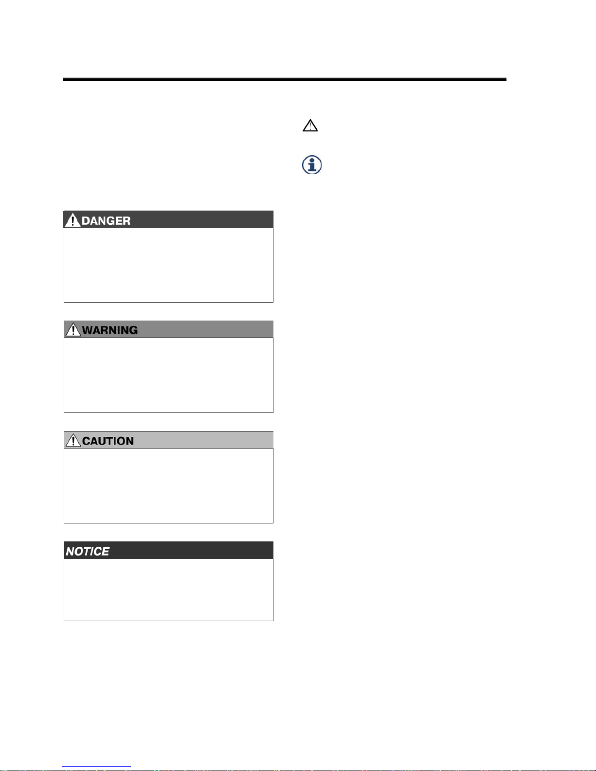
2.1 Signal words and symbols
This document contains specifically highlighted
safety instructions which are marked with one of
the following signal words depending on the
severity of the danger.
DANGER
The signal word DANGER indicates a dangerous
situation that, if not prevented, will lead to a
severe injury or death.
Information as to how the hazard can be
p
r
evented.
WARNING
The signal word WARNING indicates a
dangerous situation that, if not prevented, can
lead to a severe injury or death.
Information as to how the hazard can be
p
r
evented.
CAUTION
The signal word CAUTION indicates a
dangerous situation that, if not prevented, can
lead to a slight or moderate injury.
Information as to how the hazard can be
p
r
evented.
The signal word NOTICE indicates a situation
that, if not prevented, can lead to property
damage.
Information as to how the property damage
can be prevented.
The following symbols are additionally used:
This symbol refers to additional, safetyrelevant information.
This symbol indicates information
concerning special workflows, methods,
application of auxiliary materials, etc.
2.2 General safety instructions
Read all safety instructions and information.
Failure to comply with safety instructions and
information may lead to property damage, serious
injuries or death.
Intended use
The ZF product is exclusively intended for the
application as defined in the contract and as
agreed on at the time of delivery. Any other or
more extensive form of use does not comply with
this definition of intended use. The intended use
includes compliance with this documentation and
other applicable documents, in order to avoid
malfunctions and damage in operation.
The ZF product is designed and produced in line
with state-of-the-art technology. The ZF product is
safe to operate in its delivery status. However, the
ZF product may pose dangers if improperly used
by unauthorized, untrained and uninstructed staff
or if not used according to its intended use.
Figures might deviate from the ZF product and are
not drawn to scale. No conclusions can be drawn
with regard to size and weight.
Assembly, commissioning, maintenance and
repair
Only perform assembly, commissioning,
maintenance and repair work according to this
documentation and other applicable documents.
Page 7

Safety
EN 4161.758.102q – 2017-09 7
Observe the following points:
Employ authorized, trained and instructed staff.
Observe technical provisions.
Only use genuine ZF spare parts.
Only use genuine ZF accessories.
Only use genuine ZF special tools.
Unauthorized changes and modifications lead to
the expiry of the operator's license, warranty or
guarantee.
In case of damage, contact ZF and have the
following information on the product to hand:
Type
Parts list [BoM] number
Serial number
Operating hours
Description of damage
Observe safety instructions, valid safety regulations
and legal requirements to prevent malfunctions
and damage.
The country-specific safety regulations, accident
prevention regulations and environmental
protection provisions also apply.
Wear workwear in accordance with safety
requirements for all work. Depending on the work,
also wear personal protective equipment.
After completing the work, check correct function
and functional security.
Handling of ZF product
Unauthorized changes and modifications may
impair functional security.
Changes, modifications and applications are only
permitted with the written approval of ZF
Friedrichshafen AG.
Observe the following when working on the ZF
product:
Secure workspace.
Only carry out work at the unit when in a
voltage-free state.
Protect unit against being started accidentally.
Attach information sign in a clearly visible
position.
Perform work when motor is switched off.
Protect motor against being started accidentally.
Attach information sign in a clearly visible
position.
Do not stand beneath a suspended load.
Do not work on a suspended load.
Only use permitted means of transport and
lifting devices with sufficient load-bearing
capacity.
Close open pipelines and hoses and avoid
damage.
Observe tightening torques.
Protect cables against mechanical damage.
Noise
Noise may cause irreversible damage to hearing.
The perception of acoustic signals, warning calls
or sounds warning of impending danger is
impaired by noise.
Observe the following when working on the ZF
product:
Avoid noise.
Wear ear protection.
Operating supplies and auxiliary materials
Operating supplies and auxiliary materials may
cause permanent damage to health and
environmental damage.
Observe the following when selecting operating
supplies and auxiliary materials:
Health risks
Environmental compatibility
Material safety data sheets
Observe the following when handling operating
supplies and auxiliary materials:
Store operating supplies and auxiliary materials
in suitable and correctly labeled containers.
Seek medical help in case of injuries due to hot,
cold or caustic operating supplies or auxiliary
materials.
Observe the following to protect the environment:
Collect leaking operating supplies and auxiliary
materials in containers of a sufficient size.
Observe disposal regulations.
Observe material safety data sheets.
Page 8

Safety
8 EN 4161.758.102q – 2017-09
2.3 Product-specific safety instructions
Remove any traces of old seals or gaskets from
mating faces. Burrs or other similar rough
surfaces are to be carefully removed with an oil
stone.
Carefully cover opened gearboxes to prevent
the entry of foreign matter.
Page 9
Application and Design
EN 4161.758.102q – 2017-09 9
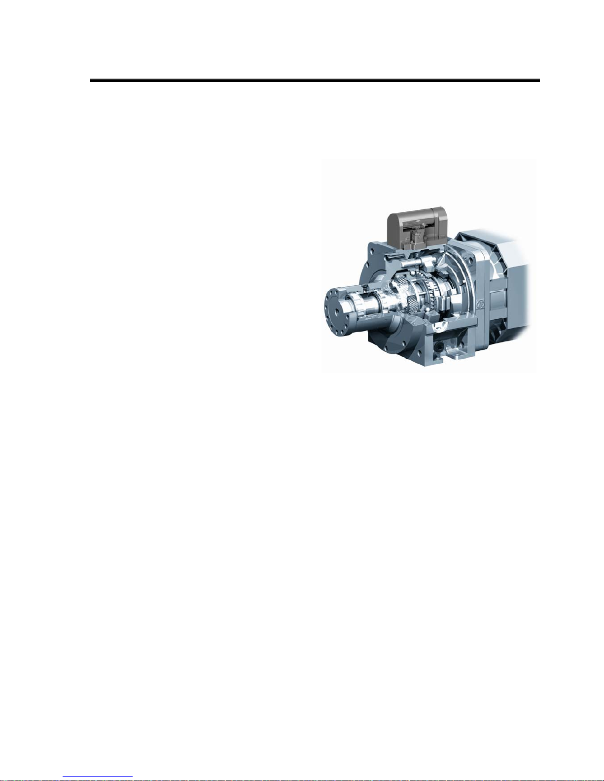
3 Application and Design
3.1 Application
The DUOPLAN 2-speed gearbox by ZF is mainly
used in machine tool drives.
As a result of the different installation positions,
the gearbox can be used, for example, for turning
machines (horizontal B5) or machining centers
(vertical V1). In addition, the gearboxes are used in
various equipment in which an increase in torque
or a reduction in speed is needed.
The gearboxes have a coaxial output and are
suited to the high speeds encountered in machine
tool engineering.
3.2 Features
2-speed gearbox for AC and DC main spindle
drives in machine tools
Compact thanks to to planetary design
Flange-mountable to all AC, DC and standard
motors
High running smoothness and low-noise
operation thanks to helical gearing
Low torsional backlash
Easy to install
High radial forces permitted on output
Combined axial and radial force thanks to
flexible output bearings
High efficiency
Electromechanical gearchange
Page 10
Application and Design
10 EN 4161.758.102q – 2017-09
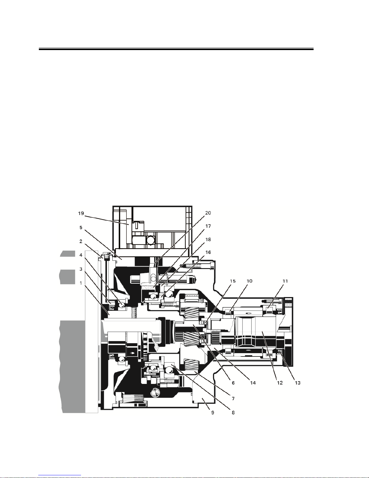
3.3 Design
The gearbox primarily comprises the following
assemblies:
Connecting parts:
Input hub (1)
Where required, adapter plate (2) with radial
shaft seal (3) and hub bearing (4)
Housing:
Gearbox housing (5)
Input:
Sun gear (6)
Ring gear (7)
Ring gear bearing (8)
Output:
Bearing housing (9)
Output bearing (10, 11)
Output shaft (12)
Radial shaft seal (13)
Planet carrier (14)
Axial bearing with cup springs (15)
Shift mechanism:
Sliding sleeve (16)
Shift fork (17)
Brake disk (18)
Shift unit:
Shift unit (19)
Selector finger (20)
Page 11
Application and Design
EN 4161.758.102q – 2017-09 11
S
2
a
1
e
2
d
b
h
l
3.4 Technical data
2K250 2K300
Nominal power max. 39 kW max. 47 kW
Nominal speed 1,500 rpm 1,500 rpm
Max. speed
when ratio i1
in direct drive i=1
(with gearbox oil
cooling and
integrated
lubricating oil
system).
See Chap. 4.6.3.3
"Connections for
integrated
lubrication oil system
and maximum
speed"
6,300 rpm
10,000 rpm
6,300 rpm
10,000 rpm
When using engine brakes/counterflow to
brake the spindles (e. g. emergency stop)
ensure that the moments of inertia do not
exceed the admissible output torques.
Braking times must be adjusted
accordingly.
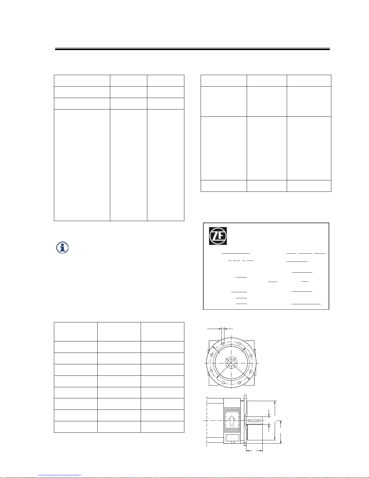
Standard installation dimensions (in mm)
according to EN 50347: 2001
Two-stage
gearboxes
2K250
FF300
2K300
FF350
Motor size 132 160
h 132 160
d 42/48/55 48/55/60
l 110-0.2 110-0.2
b 250 300
e2 300 350
a
1
– –
s2 18 18
2K250 2K300
Input nominal
torque
max. 250 Nm max. 300 Nm,
when i = 5.50
max. 250 Nm
Output torque,
max. for
i = 1.00
i = 3.07
i = 4.00
i = 5.50
250 Nm
768 Nm
1,000 Nm
1,375 Nm
300 Nm
921 Nm
1,200 Nm
1,375 Nm
Weight approx. 68 kg approx. 86 kg
Model plate (standard)
(mounted on gearbox housing)
ZF FRIEDRICHSHAFEN AG
MADE IN GERMANY
TYPE PARTS LIST
RATIO SERIAL-NO.
BACKLASH
MAX.
INPUT TURN RPM
POWER MAX.
AT RPM KW
INPUT
TORQUE NM
OIL GRADE
OIL
QUANTITY
SHITING V
UNIT W
i , - ,
MIN.
Page 12
Application and Design
12 EN 4161.758.102q – 2017-09
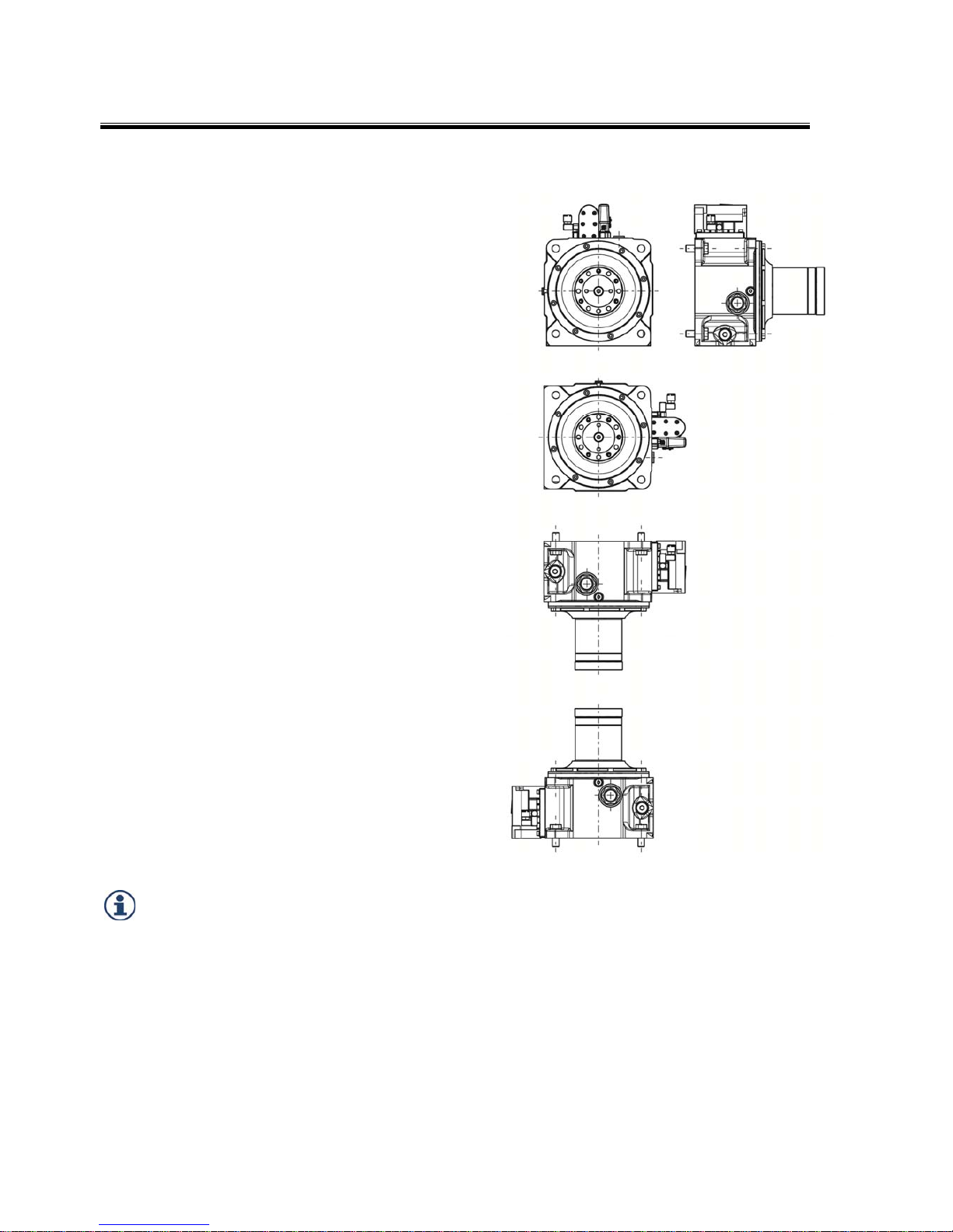
3.5 Installation positions
Horizontal B5
Horizontal B5
Shift unit on right
Gearbox rotated around longitudinal axis
(looking at output)
Vertical V1
Vertical V3
Possible damage to gearbox due to oil
leaks.
Fit breather at top in all installation
positions.
Page 13

Initial Installation
EN 4161.758.102q – 2017-09 13
4 Initial Installation
4.1 Radial run-out, axial run-out and linear
tolerances of drive motor
To ensure trouble-free operation, the motor to be
connected must comply with the specified
tolerances.
Radial run-out, axial run-out and linear tolerances
of mounting flange of electric motor:
Gearbox
type
Tolerance
A B C
L
2K250 /
2K300
0.025 0.063 0.063 -0.200
Tolerances A, B, C according to DIN 42955R
Please note the restricted tolerance of the shaft
length "L" compared to DIN.
The gearbox function will be impaired by
incorrect tolerances.
Comply with tolerance of shaft length "L".
Compliance with tolerance, especially of shaft
length "L", is important for smooth gearbox
functions. If undersized, compensate the
insufficient length using shim rings when
mounting on the motor. If oversized, the shaft
must be machined to the correct length.
Note the permissible axial forces on the motor
shaft. Also refer to ZF-DUOPLAN catalog
(4161.750.102), Chapter Performance data.
Take into account the motor shaft elongation
caused by heating in motors with fixed bearing on
the B-side (opposite the motor output shaft).
ABC
L
001064
Page 14
Initial Installation
14 EN 4161.758.102q – 2017-09
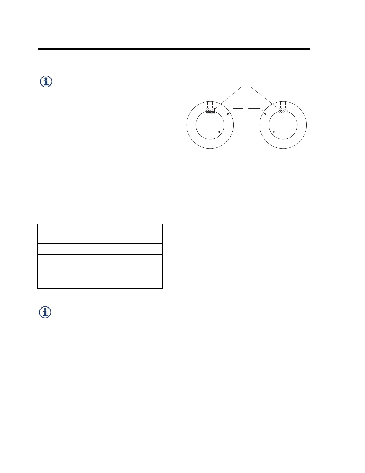
Semi-key balancing Full-key balancing
4.2 Balancing
If using motors with parallel keys, note
the balancing type.
The hubs (2) are delivered with a keyway (1) to
transmit power from the motor shaft (3) as
standard.
There are two balancing types for motor and
gearbox: semi-key and full-key. They are described
in more detail in DIN ISO 8821.
Note that the hub is balanced using the same
balancing type as the motor.
When ordering, it is therefore very important that
you state the motor along with the associated
dimensions and balancing type.
Motor output shafts with standard parallel key
according to EN 50347: 2001
Shaft diameter Parallel ke
y
Parallel key
length
42 mm A12x8 90 mm
48 mm A14x9 90 mm
55 mm A16x10 90 mm
60 mm A18x11 125 mm
In the case of motor shafts with open
keyway ends, glue the parallel key into the
groove in order to avoid axial migration of
the parallel key and/or the hub.
Clamping hubs are used for motors without
parallel keys. A balancing type is not required.
4.2.1 Semi-key balancing
With semi-key balancing, the keyway is filled by
balance compensation corresponding to
approximately half a parallel key, shape B by
default. This is based on the original parallel key,
shape, length and position used by the motor
manufacturer and is defined as a counterweight.
Since in semi-key balancing – in contrast to fullkey balancing – the joint passes through a shared
component, imbalance can arise after assembly
due to tolerance factors.
As a result, it is recommended that rebalancing
should be performed after the joined parts have
been assembled.
4.2.2 Full-key balancing
With full-key balancing, the motor shaft is
balanced with a full parallel key whereas the hub
is balanced without one. The parallel key, shape,
length and position are not important in this case.
1
2
3
Page 15

Initial Installation
EN 4161.758.102q – 2017-09 15
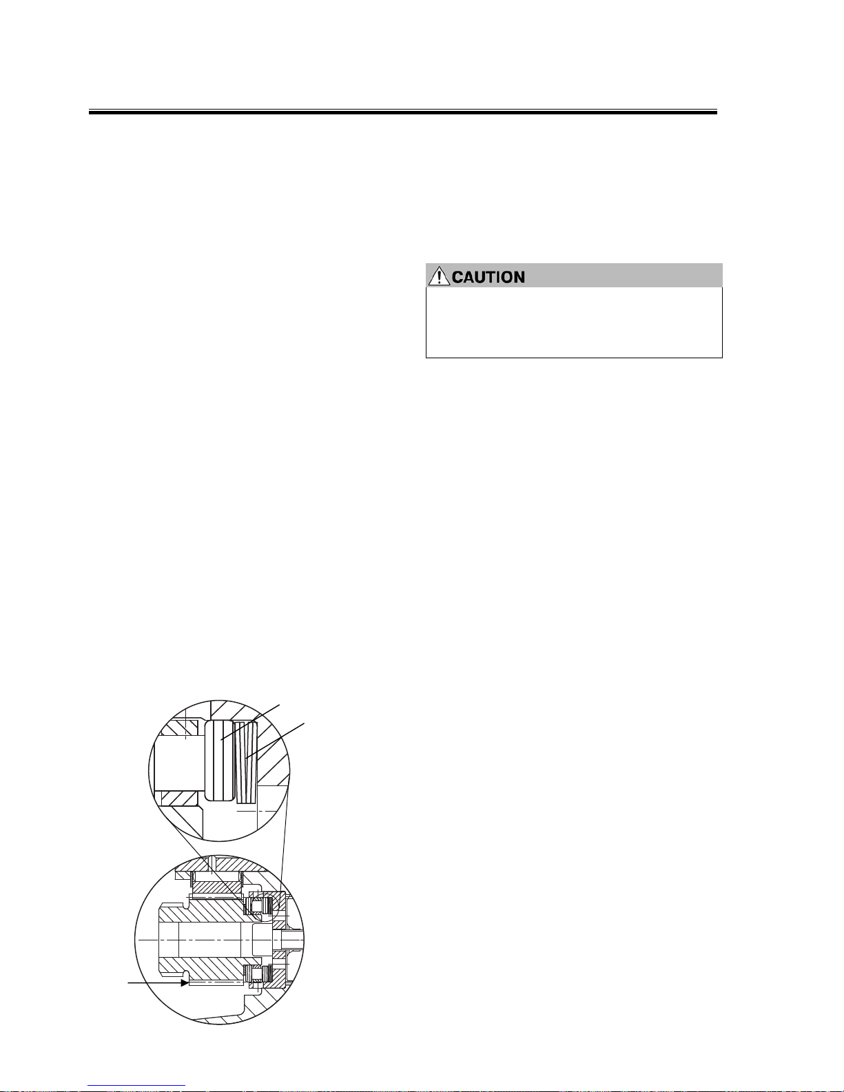
4.2.3 Motor shafts/Hubs without keyways
Clamping hubs are available for motor shafts with
diameters of 42 mm, 48 mm, 55 mm and 60 mm.
1 Hub
2 Motor shaft
Page 16
Initial Installation
16 EN 4161.758.102q – 2017-09
4.3 Adaptation, motor/gearbox
The motors must have a flange-mounting design
for mounting the gearbox.
The gearbox housing is fitted to the motor by
means of the centering adapter on the bearing
housing. This is standard.
A foot fastener is also available on the gearbox
housing for 2K250 and 2K300.
Depending on the motor version, different gearbox
variants are used. The gearbox mounting differs
accordingly.
Reference dimensions for hub position
Gearbox type Dimension D in mm
2K250 125.0-0.2
2K300 125.0-0.2
In the case of motors with fixed bearing on the
B-side, the dimension is D = 124.5-0.2.
If using spacer disks, shim rings of various
thicknesses are also supplied. These are used to
compensate for motor shaft length tolerances and
therefore to comply with control dimension "D".
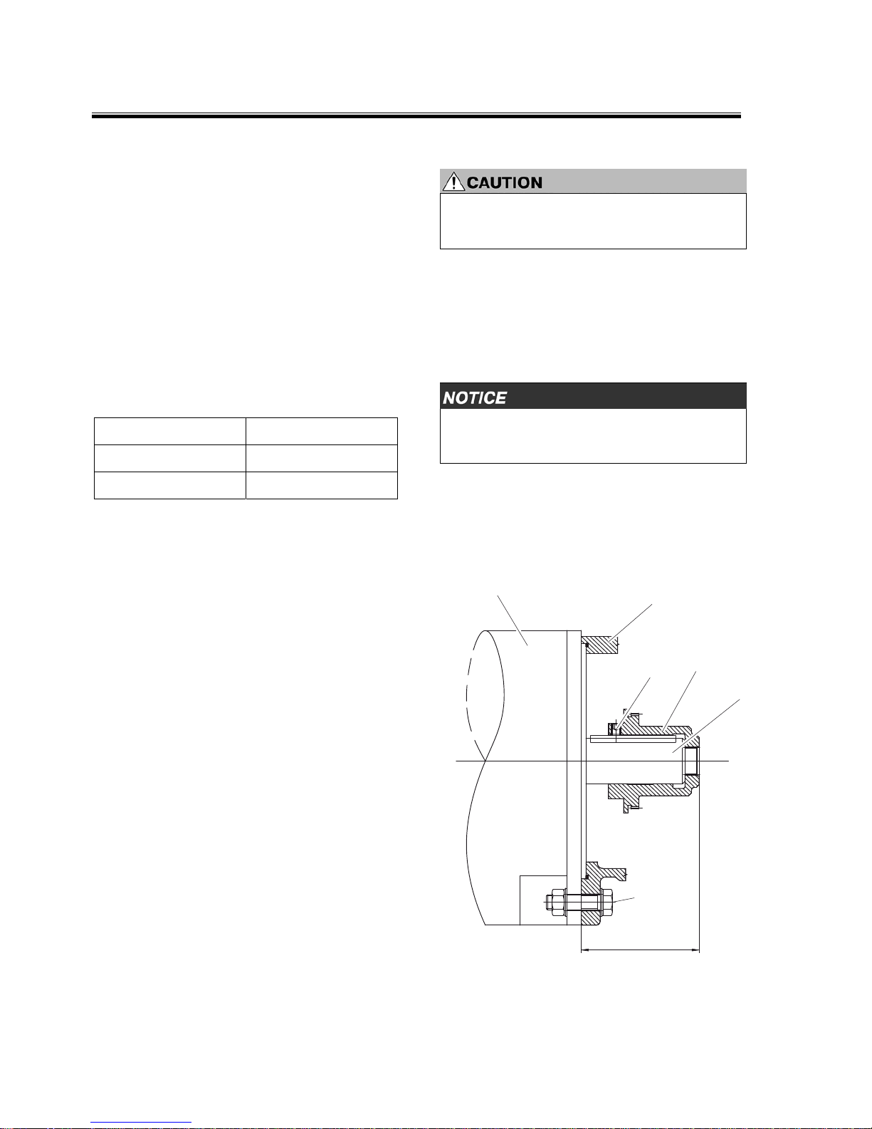
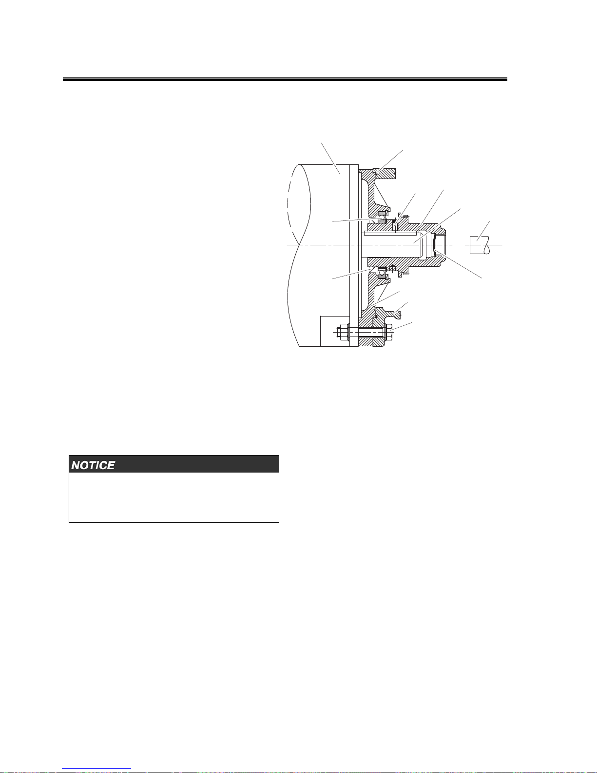
4.3.1 Open design
Open design describes the gearbox without
adapter plate, but with a seal to prevent gearbox
oil ingress on the motor output shaft (2).
The input hub (1) is delivered loose with the
gearbox. Clean the fitting surfaces of motor (3)
and input hub. Check the motor shaft and, if
necessary, correct in terms of concentric running,
axial run-out and length according to Chap. 4.1.
If undersized, use shim rings to compensate. If
oversized, shorten motor shaft. A little grease must
also be applied to the motor shaft.
Risk of burns due to contact with hot surfaces.
Slight to moderate injury possible.
Wear protective gloves.
After cleaning the fitting surfaces, the input hub
must be heated to approx. 120 °C from the
opening and slid onto the motor shaft until the
stop is reached, using shim rings if required.
Then check reference dimension "D".
Risk of motor shaft damage if input hub is not
heated sufficiently.
Heat input hub to approx. 120 °C.
Tighten the set screw (9) and secure it to prevent
it from turning, refer to Chap. 4.3.6.
3
6
9
1
2
11
D
Page 17

Initial Installation
EN 4161.758.102q – 2017-09 17
4.3.2 Closed design with hub bearing and
shaft sealing ring
Variant with ball bearing (4), containing additional
bearing mounting for input hub (1), to prevent
axial migration of the input hub.
For assembly, separate input hub (1) with adapter
plate (5) from gearbox housing (6). Clean the
fitting surfaces of motor (3) and input hub. Check
the motor shaft (2) for concentric running and
axial run-out according to Chap. 4.1. A little grease
must also be applied to the motor shaft.
Risk of burns due to contact with hot surfaces.
Slight to moderate injury possible.
Wear protective gloves.
After cleaning the fitting surfaces, the input hub
must be heated to approx. 120 °C from the
opening and slid onto the motor shaft until the
stop is reached.
Control dimension "D" is set ex works.
Risk of motor shaft damage if input hub is not
heated sufficiently.
Heat input hub to approx. 120 °C.
During assembly, it must be possible to easily slide
the input hub onto the motor shaft up to the point
where the adapter plate makes contact with the
motor flange.
Do not use adapter plate to slide hub onto
motor shaft.
Check by ensuring that the adapter plate is making
contact but can be freely rotated. This ensures that
there is no hub bearing preload.
Tighten the set screw (9) and secure it to prevent
it from turning, refer to Chap. 4.3.6.
The radial shaft sealing ring in the drive motor
must be removed on the output end when the
closed design is used.
3
10
9
1
2
5
6
11
D
7
4
Page 18

Initial Installation
18 EN 4161.758.102q – 2017-09
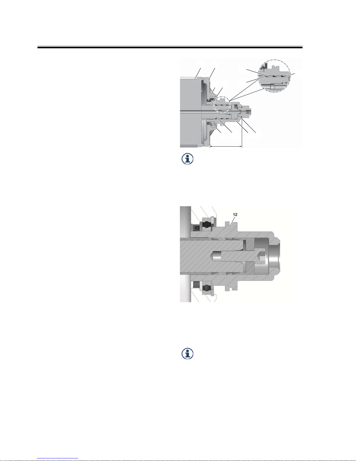
4.3.3 Closed design
(with shaft seal)
This variant contains an adapter plate (5) with
shaft sealing ring (7), making the gearbox a
compact, self-contained unit.
Adapter plate and input hub (1) are delivered
separately and loose. Clean the fitting surfaces of
motor (3) and input hub. Check the motor shaft for
concentric running and axial run-out according to
Chap. 4.1. A little grease must also be applied to
the motor shaft.
Risk of burns due to contact with hot surfaces.
Slight to moderate injury possible.
Wear protective gloves.
After cleaning the fitting surfaces, position the
adapter plate with radial shaft seal on the motor
housing. The input hub must be heated to approx.
120 °C from the opening and slid onto the motor
shaft until it reaches the stop, i.e. spacer disk (12)
with shim rings (13).
Then check control dimension "D" and vary using
shim rings if required.
Risk of motor shaft damage if input hub is not
heated sufficiently.
Heat input hub to approx. 120 °C.
Tighten the set screw (9) and secure it to prevent
it from turning, refer to Chap. 4.3.6.
Thoroughly grease the radial shaft seal and
input hub before assembly. During
assembly, it is essential that the radial shaft
seal's sealing lip is positioned correctly and
that the direction of sealing is correct.
3
10
9
1
2
5
6
11
D
7
12
13
Page 19

Initial Installation
EN 4161.758.102q – 2017-09 19
4.3.4 Open design with adapter ring
The adapter ring allows adaptation to different
connecting dimensions. Sealing is required on the
motor output shaft.
Adapter ring (5) and input hub (1) are delivered
loose. Clean the fitting surfaces of motor (3) and
input hub. Check the motor shaft (2) for concentric
running and axial run-out according to Chap. 4.1.
A little grease must also be applied to the motor
shaft.
Risk of burns due to contact with hot surfaces.
Slight to moderate injury possible.
Wear protective gloves.
After cleaning the fitting surfaces, position the
adapter ring on the motor housing. The input hub
must then be heated to approx. 120 °C from the
opening and slid onto the motor shaft (2) until it
reaches the stop, i.e. spacer disk (12) with shim
rings (13).
Then check control dimension "D" and vary using
shim rings if required.
Risk of motor shaft damage if input hub is not
heated sufficiently.
Heat input hub to approx. 120 °C.
Tighten the set screw (9) and secure it to prevent
it from turning, refer to Chap. 4.3.6.
3 5
10
6
9
1
2
11
11
D
12
13
Page 20
Initial Installation
20 EN 4161.758.102q – 2017-09
4.3.5 Closed design with hub bearing,
shaft sealing ring and keyless hub
When mounting on motor with smooth motor
shaft without parallel key, ring clamping elements
and pressure pieces must be used between motor
shaft and input hub for torque transmission. A
centric screw thread in the motor output shaft is
absolutely essential.
Clean the fitting surfaces for motor (1), motor shaft
(10) and input hub (9).
Check the motor shaft (10) for concentric running
and axial run-out according to Chap. 4.1.
Loosely preassemble the counter-holder (4), ring
clamping elements (5+6), bush (12), pressure
piece (7) and screw connection with a thread-lock
(8). Pay attention to the position of the ring
clamping elements. First install the inner (6) and
then the outer (5) ring clamping elements in the
package on the motor shaft.
Depending on the version, slide input hub onto
motor shaft with or without adapter plate (2).
Attach the ring clamping elements by hand with
the help of the screw connection. Tightening the
screw connection causes the hub (and the adapter
plate, if fitted) to move axially towards the motor.
Take this into consideration by using a lead
dimension of +0.4 mm with 3 ring clamping
elements and a lead dimension of +0.6 mm with
4 ring clamping elements respectively.
Tighten screw connection (8) to 300 Nm for M16
and to 510 Nm for M20.
Note maximum permissible tightening torque for
thread in motor shaft. In adaptations without
coolant flow, use screws of strength class 10.9.
Check dimension D and concentric running of hub.
Additional internal sealing is no longer needed if
using ring clamping elements. The number of ring
clamping elements and bushes may vary
depending on the motor.
If using screw connections with a hole for the
coolant to flow through, be aware of O-rings and
grease them before assembly.
To prevent twisting of the motor shaft and input
hub when tightening, the input hub must be
blocked. This can be done using ZF special tool
1X46.188.387.
D
6
5
7
9 8
11 10
3 4
21
Do not grease: motor shaft (10) and input
hub bore (9).
Apply a little oil: cone-shaped face of ring
clamping elements (5+6).
The counter-holder is supported on the shoulder of
the motor shaft. Ensure a large contact surface.
In the closed version without hub bearing, the seal
running surface for the radial shaft seal on the
input hub is to be greased before assembly. Note
position of sealing lip when sliding on input hub.
When using the closed design with hub
bearing (11) and radial shaft seal (3), do
not use adapter plate to slide input hub
onto motor shaft. Once the screw
connection has been tightened, the adapter
plate must make contact with motor
housing and still be free to rotate. The hub
is then mounted free from pretension.
Page 21
Initial Installation
EN 4161.758.102q – 2017-09 21
4.3.6 Mounting the gearbox
The M8 set screw (9) must be screwed in and
tightened to 18 Nm until firmly home on the
parallel key. Apply liquid seal to the set screw
before installation.
During assembly, ensure that the O-ring (10) is
positioned correctly. The O-ring is delivered loose
with the gearbox and is inserted in the sealing ring
groove in the housing (6) with grease.
Check position of gearbox shift mechanism. The
sliding sleeve must be in gear 1 shift position
("slow" stage).
Take the gearbox and place it on the motor flange.
Carefully connect the sun gear to the input hub.
The external spline of the sun gear must be
fed into the internal spline of the hub.
This process can be simplified by turning the
gearbox output slightly to the left/right.
Gearbox housing, adapter plate and motor are
secured to one another with four or eight hexagon
bolts (11).
Fill the gearbox with oil and/or connect the
recirculating lubrication and power supply. The
breather outlet must be mounted at the top in all
installation positions. The breather is screwed in to
position B5 ex works.
The gearbox is now ready for use.
The gearboxes can be operated under the same
degrees of protection as those in effect for AC
and DC motors.
During installation ensure that the cooling air of
the motor can flow freely in and out.
Before initial operation of the electric motor/
gearbox drive assembly, check that the gearbox
output can be turned by hand.
For drive assemblies which are fastened to the
gearbox flange or gearbox housing, the motor can
be supported on the B-side free from distortion.
Gear 1 shift position:
A Brake disk
B Sliding sleeve
A
B
Page 22

Initial Installation
22 EN 4161.758.102q – 2017-09
4.3.7 Version with pulley drive
The pulley will be centred on the outer diameter of
the drive flange (K6 tolerance), friction-locked in
place and secured using screws, whereby the
permitted torque must be taken into account.
The pulley must have a balance rating of 6.3, as
per VDI Directive 2060, in order to ensure low
vibration operation.
It is mandatory to lubricate the bearings fitted in
the pulley drive with 0.5 – 1.0 l/min via oil
connector ‘S’ in the drive housing.
Note maximum tensile force of belts
(refer to Chap. 4.4.1).
The average belt power must lay in between the
bearings. During assembly, it must be possible
to easily slide the belt pulley onto the input
flange, heat the belt pulley if necessary.
Page 23

Initial Installation
EN 4161.758.102q – 2017-09 23
4.3.8 Closed design with hub bearing,
shaft sealing ring and clamping hub
The motor is mounted on the gearbox using
an adapter flange with clamping hub. The
motor shaft is connected to the clamping
hub with a force fit.
The gearbox with clamping hub may only be fitted
on motors with a smooth motor shaft.
1 Adapter plate
2 Motor shaft
3 Motor flange
4 Mounting screw
5 Clamping hub
6 Sleeve
7 Clamping screw
8 Cover plate
9 Output shaft
Mounting gearbox on motor:
First the motor shaft (2), the bore of the clamping
hub (5) and, if present, the sleeve (6) must be
degreased. Then insert the sleeve into the
clamping hub until the stop is reached. The
clamping hub (5) must be positioned so that the
clamping screw (7) can be tightened via the
access bore. The cover plate (8) is removed for
this purpose. The motor shaft (2) is guided
(centered) into the clamping hub (5) until the
motor flange (3) makes contact with the adapter
plate (1). Ensure that the motor shaft does not jam
in the clamping hub. The fixing bores on the motor
flange and adapter plate must match precisely.
The motor is mounted on the gearbox with four
appropriate mounting screws (4), with a screw-in
depth into the adapter plate of 15 to 25 mm.
Tighten clamping screw (7) to 260 Nm with torque
wrench, socket wrench extension and hex socket
insert (WAF 14). If necessary, block the output
shaft (9). Close off the access bore again with
cover plate (8).
Dimension A for extension of hexagon socket
wrench
Adapter plate 2K250, A = 100 mm
Adapter plate 2K300, A = 125 mm
Page 24

Initial Installation
24 EN 4161.758.102q – 2017-09
4.3.8.1 Spindle cooling (TSC) version,
feeding emulsions, hydraulic oils or
air-oil mixtures
Mounting gearbox on motor:
Coat thread of connecting piece (1) with sealing
compound. Screw connecting piece with preassembled and greased O-rings (2) into motor
shaft (3) by hand until stop is reached. Use jaw
wrench (WAF 27) to tighten connecting piece to
130 Nm, blocking motor shaft in the process.
Follow the description provided in Chapter 4.3.8
for the rest of the mounting process.
1 Connecting piece
2 O-rings
3 Motor shaft (hollow shaft)
Installing the rotary union:
Apply grease to both ends of tube (5) and place in
rotary union (4). Carefully guide tube through
greased radial shaft seal (1) into gearbox. Coat the
four cap screws (3) with hex socket (WAF 3) with
sealing compound and tighten to 2.8 Nm with
torque wrench.
1 Radial shaft seal
2 Output shaft
3 Cap screw
4 Rotary union
5 Tube
Page 25

Initial Installation
EN 4161.758.102q – 2017-09 25
4.4 Output
Please note the details relating to the resultant
force in the installation drawings.
4.4.1 Version with belt output
The belt pulley is centered to the outside diameter
of the output flange (tolerance K6), attached and
secured with friction engagement using screws,
while noting the permissible tightening torques.
For low-vibration operation, the belt pulley should
be balanced to quality 6.3 according to VDI
directive 2060.
Possible damage due to bearing overload.
Note maximum tensile force of belts.
To avoid overloading the bearings, note the
maximum tensile force when tensioning the belts.
The average belt power must lay in between the
bearings. During assembly it must be possible to
easily slide the belt pulley onto the output flange,
heat the belt pulley if required.
4.4.2 Version with coaxial output
For the version with coaxial output (stub shaft), the
balancing type should also be noted for the output
(refer to Chap. 4.2). The gearbox is delivered with
full-key balancing.
The parallel key dimensioning can be seen in the
installation drawing. Fix the parallel keys using a
set screw in any case.
4.4.3 Version with TSC
The version with TSC (Through Spindle Coolant)
serves to transmit cooling lubricant, hydraulic oils
or air-oil mixtures
1)
through the gearbox to the
spindle. To ensure liquid transfer during gearbox
under speed differential, a rotary union is needed,
which is subject to wear depending on the load
and the status of the medium. Depending on the
system used, leakage drips can occur when
activating and deactivating. This can be traced
back to design measures in the coolant circuit. A
transparent coolant return allows the status of the
rotary union to be assessed.
The warranty for the rotary union is limited to 12
months.
Information regarding the product, function,
operation and installation of the rotary union can
be found in the operating instructions
4161.758.030 (German)
4161.758.130 (English)
1)
No abrasive or solvent additives are permitted
in the fluids.
4.5 Electrical connection, gearchange
The electrical connection may only be performed
by a qualified electrician.
Possible damage to shift unit due to incorrect
connections.
Connect shift unit as described in Chap. 4.5.1
and 4.5.2.
The gearbox is connected electrically with the
8-pole Harting connector supplied (HAN 8 U). The
plug connection is located on the shift unit.
4.5.1 Shift unit
Technical data:
Power consumption 84 W
Supply voltage 24 V DC ±10%
Max. pickup current 5 A
Nominal current: 3.5 A
Protection class IP64
The required cable lead diameter is 1.5 mm².
Ensure the supply voltage of 24 V DC and the
current consumption of 5 A on the shift unit plug.
Losses due to cable length and transition
resistances are to be taken into consideration.
Scope of supply:
Sleeve housing, screw connection, socket insert
and 8 Harting AWG16 contact bushings. The shift
unit is only available as a complete part.
Page 26

Initial Installation
26 EN 4161.758.102q – 2017-09
Gearbox shift mechanism:
During the gear change, the motor shaft
and/or gearbox output is without load
(unbraked).
Shifting is performed through application of 24 V
on pin 2 and 3. The polarity of the applied 24 V DC
voltage is decisive for the gear stage.
In gear 1 => Pin 2: + / Pin 3: ‒
In gears 2 and 3 => Pin 2: ‒ / Pin 3: +
During the gear change, the main spindle motor
should make the shaft oscillate +5° or -5° at a rate
of 1 to 5 rotation direction changes per second. A
larger pendulum motion may cause damage to the
meshing gears. The gears usually already mesh at
the first rotation direction change, so that the
switchover time is approx. 300 to 400 ms.
On average, this means: n
Mot
= 5°/s = 5° 60/min =
300°/min = 300/360 rpm = 0.83 rpm.
Conversion
Pendulum speed
pendulum rotary motion
Speed
[rpm]
Angle
[°/min]
Time
[sec]
Angle
[°/sec]
0.25 90 3.33 5
0.50 180 1.67 5
1.00 360 0.83 5
2.00 720 0.42 5
3.00 1,080 0.28 5
4.00 1,440 0.21 5
5.00 1,800 0.17 5
Because of the different masses and associated
drag torques of the spindle, the machine optimum
is to be determined on the basis of shift tests.
The limit switch signals of S1 – gear 1 (contact 4)
and S2 – gear 2 (contact 6) serve to shut off the
shift unit once the gear change is complete.
After the limit switch signals have been reached,
the shift unit is allowed to be live for a maximum
of 0.5 seconds. The limit switch signals must be
monitored during operation.
The limit switches must only be energized with the
control current (0.1 to 0.5 A), not the changeover
current (5 A).
The changeover current must not be present for
more than 2 seconds.
If the number of resistors is small, a lower control
current may also be used.
The control current for end-position monitoring
must be ensured depending on length, line/
transition resistances and number of connection
points. Increased resistances caused by corrosion
must also be considered after some time.
Switching of inductive loads by means of the
control current requires it to be wired parallel to
the load by a diode.
If the limit switches detect that a gear is no
longer reliably engaged, the control system must
initiate appropriate measures, such as emergency
shutoff etc.
Electromagnetic fields may falsify the signals of
limit position monitoring.
Do not route control lines in parallel with
cables for the voltage supply or shield control
lines.
The shift sequence is to be monitored; if
necessary, a timing element must reverse the gear
change if no limit switch signal (S1/S2) is received
after approximately 2 seconds. Afterwards repeat
the gear change command, the main spindle
motor must not be released.
Rotation direction
changes
Page 27

Initial Installation
EN 4161.758.102q – 2017-09 27
Diagram for shift unit with two shifting positions
(standard) or three shifting positions (with neutral
position):
Gear 1 ==> e.g. 4:1
Gear 2 ==> 1:1
Gear 3 ==> S3 neutral position, idling
(option)
S3
S1 S2
optional
M
34
4
2
1
34
blue
blue
grey
grey
black
blue
black black
green
X8
43526
8
17
The electromechanical gear change is undertaken
by a shift unit on the gearbox, which is driven by a
direct current motor (24 V DC). The gear shift
element is a positively locking, axially movable
shift selector that acts on a sliding sleeve.
The limit positions are monitored by limit position
switches in the shift unit. Monitoring of timing is
provided in the control unit.
When shifting from gear 1 to gear 2 or vice versa,
the motor is to be energized. The rotation direction
is changed by means of pole reversal.
Gearbox with neutral position
The neutral position can only be approached from
gear 1.
As soon as the S3 limit position switch receives
the signal, the direct current motor is to be shut
down by means of a dynamic motor stop (quick
stop).
Under certain operating conditions (e.g. V3
installation position, higher line resistances), a
variable timing element may be needed in the
gearbox control consult ZF.
Page 28
Initial Installation
28 EN 4161.758.102q – 2017-09
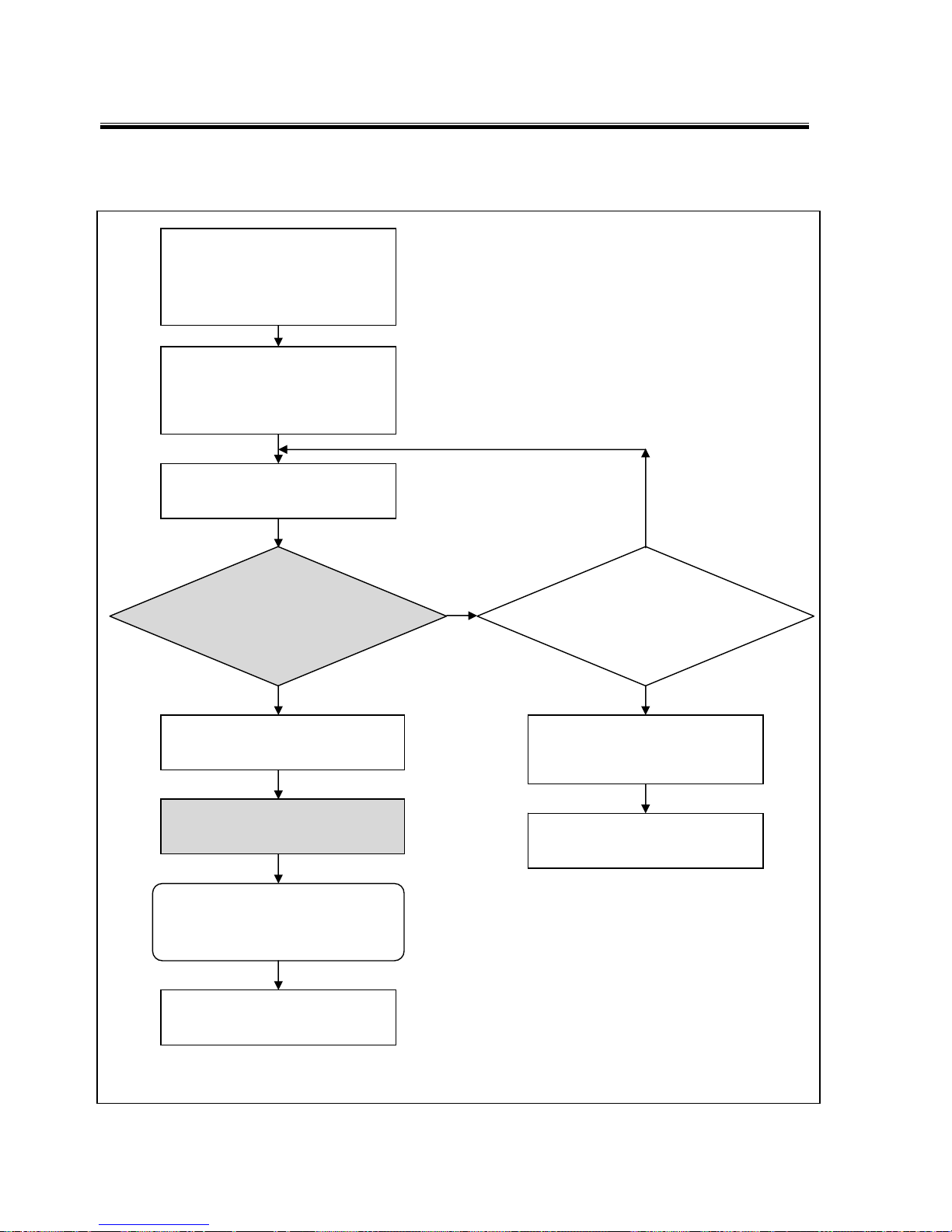
4.5.2 Shift logic
1) Alternatively, the first switching test can be performed without oscillating, but this requires a de-energized main spindle motor or
minor output-end masses.
Decelerate main spindle motor from
operating speed to zero.
Keep controller release (signal)
connected with power converter.
Apply desired oscillating speed to
converter and speed controller
without delay.
1)
Shift unit energized
(pin 2 and 3)
Gear change
must be completed within 2
seconds. (Feedback signal from limit
switch S1, S2 or S3 from the shift
unit)
Shut off desired
oscillating speed.
After 200 ms to max. 500 ms
shift unit OFF.
Gear change
complete.
Number of gear
change attempts > 5
all from the respective starting
position (pole reversal)
Gear change not accomplished:
switch off
main spindle motor.
Check system.
N
N
Y Y
Start main spindle motor
Page 29

Initial Installation
EN 4161.758.102q – 2017-09 29
4.6 Lubrication
4.6.1 Splash lubrication
The B5 standard version of the gearbox has splash
lubrication.
Splash lubrication is suitable for intermittent
operation. Frequent gear shifts, different
speeds and downtimes, such as those
encountered when changing tools, are
assumed.
Possible damage to gearbox due to insufficient
oil quantity and/or running dry.
Fill gearbox oil up to center of oil level gage
glass.
The actual oil level is binding for the amount of oil
to add. The number of liters stated on the model
plate for the relevant gearbox is a reference value.
If the gearbox is installed at an angle, which may
be the case with certain belt tensioning equipment, an oil level tube with calibration mark must
be fitted in place of the oil level gage glass.
Ensure the same oil level as that obtained when
the gearbox is installed horizontally (also refer to
installation drawing).
An oil sensor can occasionally be used to
check the oil level before starting the
machine. The oil sensor can be screwed
into connections D or E (figure, page 31) of
the gearbox housing. (Oil sensor order no.
4161.298.045, Balluff data sheet available
on request)
4.6.2 Recirculating lubrication
Two connecting pieces (hose fittings) with
M42x1.5 and M22x1.5 thread are optional
accessories, order no. 4161.106.016.
Recirculating lubrication enables efficient gearbox
lubrication and cooling. This improves the
gearboxes performance and less heat is
introduced into the machine.
Gearbox failure due to insufficient lubrication.
Gearboxes in the V1 vertical and V3 vertical
installation positions must be operated with
recirculating lubrication.
In the 2K250/2K300 gearboxes, the V1 vertical
and V3 vertical installation positions require
recirculating lubrication. The type of recirculating
lubrication depends on the operating temperature
level required.
Because of the centrifugal forces acting on the oil,
there may be insufficient lubrication at the gearing
if operated continually in direct drive.
Occasionally changing gear (ratio) and then
starting the motor (n
Mot
=1,000 rpm) feeds oil to
the gearing and prevents the gearing from being
loaded on the one side linked to the selected
position.
Some applications require a very low operating
temperature level which can be obtained by
connecting a gearbox oil supply with oil cooling
specifically designed for this purpose. The relevant
gearbox versions are prepared accordingly.
To achieve ideal gearbox cooling without
influencing lubrication, various connectors are
available for recirculating lubrication on the
gearbox depending on the installation position and
mode of operation.
The figures on page 31 show the oil inlet and
outlet points on the gearbox. The precise
measurements can be found on the respective
installation drawings.
After initial operation, the oil level must be in the
center of the oil level gage glass, top up oil if
required.
The pump, oil tank and heat exchanger
components must be positioned below the
gearbox oil level. If the oil return is
connected according to Chap. 4.6.3.2,
limp-home (emergency control)
characteristics are assured.
Page 30

Initial Installation
30 EN 4161.758.102q – 2017-09
The following scenarios are unproblematic:
The oil level in the tank falls during operation as
a result of the gearbox oil in the gearbox
foaming.
The formation of an oil-air emulsion in the oil
return and in the tank.
4.6.2.1 Recirculating lubrication during
V1/B5 operation
For the position of the oil inlets and outlets, refer
to Chap. 4.6.3.2.
The oil inlet is connected in place of the oil drain
plug.
Oil inlet quantity 1.5 to 2 l/min.
One oil level gage glass is removed and replaced
with a screw-in drain pipe (M42x1.5).
In the V3 vertical installation position, the gearbox
oil can be supplied both radially and centrally.
The outlet line should be dimensioned so as to
prevent oil return blockages in the gearbox
(D
i
approx. 20 mm).
4.6.2.2 Recirculating lubrication with heat
exchanger
A heat exchanger is installed in the recirculating
lubrication to achieve an additional reduction in
temperature.
4.6.2.3 Recirculating lubrication with
intermediate tank
For effective oil cooling, the tank volume should be
at least ten times the amount of oil circulated.
To avoid gearbox damage from running dry, ZF
recommends installing an oil level sensor on the
intermediate tank.
Use a 60 μm filter and a safety non-return valve (1)
at the gearbox oil inlet.
This arrangement permits continued operation
using splash lubrication, refer to Chap. 4.6.1.
Downstream of the gearbox, the oil return line
must always be below the oil outlet so that the oil
level in the gearbox cannot rise.
Installation example B5
1
Page 31

Initial Installation
EN 4161.758.102q – 2017-09 31
4.6.3 Connections for lubrication
4.6.3.1 Connections for initial fill/
oil change
Installation
position
Oil fill Oil drain
B5
I
G, F, H
B5 rotated D
V1 D, E by drawing off
(for version with output shaft)
P (for version with output flange)
V3 H
Page 32

Initial Installation
32 EN 4161.758.102q – 2017-09
4.6.3.2 Connections for recirculating lubrication in standard applications
Installation
position
Oil inlet connection Max.
pressure
Oil return port
V1
(closed
variant)
M (0.5 l/min) and
T (1.0 l/min)
0.5 bar
0.5 bar
D
Main direction of
rotation
counterclockwise *
E
Main direction of
rotation
clockwise *
V1
(open variant)
T (1.5 l/min) 0.5 bar
B5
(closed variant)
M (0.5 l/min) and
T (1.0 l/min)
0.5 bar
0.5 bar
B5
(open variant)
G (1.5 l/min) main direction of rotation
counterclockwise* or
F (1.5 l/min) main direction of rotation
clockwise*
1.5 bar
B5 rotated
(open on right)
I or F (1.5 l/min) 1.5 bar H
V3
(closed variant)
M (0.5 l/min) and
T (1.0 l/min)
0.5 bar
0.5 bar
H
V3
(open variant)
T or P (1.5 l/min) 1.5 bar H
* As seen facing gearbox output
The principal factor in determining the oil supply volume is always the volume that flows out of the
oil return. In the case of gearboxes with a belt pulley drive, consider the additional lube oil bore "S"
(refer to Chapter 4.3.7).
Page 33

Initial Installation
EN 4161.758.102q – 2017-09 33
4.6.3.3 Connections for integrated lubrication oil system and maximum speed
For applications with a maximum speed of 10,000 rpm and/or a dry sump, the T connection with integrated
lubrication oil system is mandatory. Furthermore, gearbox oil cooling >0.3 kW and a circulating oil volume
>15 liters is required.
All versions include T connection with integrated lubrication oil bore.
When ordering, note the corresponding Machine-Readable Product Designation (MLFB) number for the
integrated lubrication oil system.
The integrated lubrication oil system is only available with the closed variant.
The recommended oil viscosity for integrated lubrication oil system is HLP 22 according to ISO VG 22.
With dry-sump lubrication, HLP 10 according to ISO VG 10 can be used if it can be ensured that the gearbox
oil outlet temperature is below 65 °C at all times.
Installation position Oil inlet connection Max. pressure Oil return connection
V1
(closed variant)
T
(1.5 l/min)
and
M
(approx. 0.5 l/min)
0.5 bar
0.5 bar
D or E
V3
(closed variant)
T
(1.5 l/min)
and
M
(0.5 l/min)
0.5 bar
0.5 bar
H
B5
(dry sump)
T
(1.5 l/min)
and
M
(0.5 l/min)
0.5 bar
0.5 bar
H
B5
(rotated, dry sump)
T
(1.5 l/min)
and
M
(0.5 l/min)
0.5 bar
0.5 bar
D
The principal factor in determining the oil supply volume is always the volume that flows out of the
oil return.
Page 34
Initial Operation/Maintenance
34 EN 4161.758.102q – 2017-09
5 Initial Operation
5.1 Initial inspection
Before initial operation, the correct installation
condition of the gearbox must be checked.
Mechanical fastening
Motor flange-mounting
Gearbox oil connections
Oil supply/oil fill ensured
Electrical connections
Ease of movement (can be turned by hand)
Vertical breather position
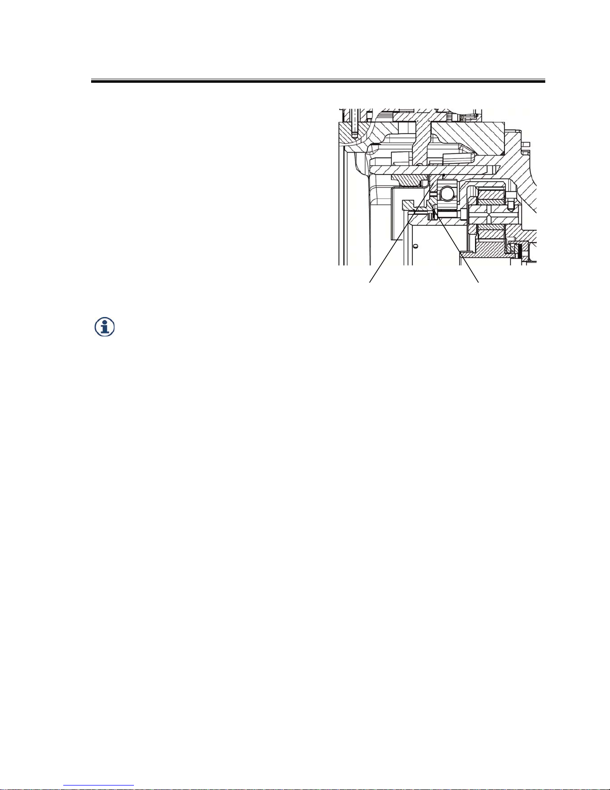
5.2 Checking setting dimension of sun
gear
Control dimension "A": 125.1 mm, tolerance
+0.2 mm, measured between housing connection
surface and front side of sun gear. When measuring, press the sun gear towards the output until it
reaches the stop.
The dimension is set correctly ex works.
Check the dimension after inserting the sun gear,
e. g. following disassembly. Dimension "A" is
correct if the spring assembly (2) and shims (1)
are correctly installed in their entirety (see detailed
figure below).
6 Maintenance
6.1 Oil change
Oil change interval: every 5,000 hours of
operation
Risk of burns due to contact with hot oil.
Slight to moderate injury possible.
Wear protective goggles.
Wear protective gloves.
Allow used oil to drain at operating temperature
into a suitable container.
The drain connections differ depending on the
installation position and gearbox version (refer to
Chap. 4.6.3.1).
Fill new gearbox oil at connection I.
The oil level is correct when it reaches the center
of the oil level gage glass with a stationary
gearbox.
The oil level is binding. The number of liters stated
on the model plate is a reference value.
If available, briefly allow oil pump to run after
filling with oil in order to vent, top up oil if
required.
1
2
A
Page 35

Repair
EN 4161.758.102q – 2017-09 35
7 Repair
In the event of gearbox malfunctions, first check
the connected components and their connections.
Carefully document the type of fault so as to assist
manufacturer diagnosis (refer to Chap. 7.1).
Repairs to the gearbox itself may only be
performed by ZF Friedrichshafen AG or by
authorized ZF after-sales points.
7.1 Gearbox fault checklist
If you encounter drive unit faults, please first check
the solutions listed in Chapter 8.
If this does not solve the problem, you will need to
provide the following information for diagnosis at
ZF Friedrichshafen AG or an authorized ZF
aftersales point:
Gearbox data on the model plate:
Typ: . . .
(Type)
Parts list [BoM]: 4161 . . . . .
(Parts list no.)
Serien-Nr.: . . . . .
(Serial no.)
Motor data on the model plate:
Manufacturer: . . .
Type/Size: . . .
Questions for fault diagnosis:
Is oil level gage glass on gearbox dark/black?
Is there a smell of burning oil at the oil
breather?
Gearbox running noise in 1:1 or 4:1 gear ratio,
or only in one rotation direction or in both
rotation directions?
Before the running noise occurred, was the
machine operated in only one gear ratio (1:1)
for an extended period of time?
Did the running noise occur after changing the
machine's cycle or was the machine cycle
unchanged?
Was any maintenance carried out on the
machine before the fault occurred and, if yes,
what did this maintenance work involve?
No gear change or gear loss in the event of a
shift problem?
Does the shift logic conform to ZF
specifications? (Refer to page 28)
What is the shift unit voltage during the shift
sequence?
Page 36
Repair
36 EN 4161.758.102q – 2017-09
7.2 Gearbox – disassemble
(e. g. version with adapter plate, shaft seal and hub
bearings)
Proceed accordingly in the case of other versions.
Switch off the machine
Switch off the power supply
Disconnect the electrical connections
Disconnect the gearbox oil connections,
drain the gearbox oil
Undo the mounting bolts (11)
Pull gearbox (6) off adapter plate (5) and
input hub (1)
7.3 Input hub with parallel key
Undo the set screw (9) used to radially secure the
parallel key.
Use a removing device, e.g. three-arm puller, to
pull off input hub against the motor shaft without
heating the hub:
Press off against a removing aid (12) on the cover
(8). Keep turning the puller until the cover is at
the spacer disc/motor shaft.
The cover plate may cause the input hub to jam
when being pulled off.
Position cover plate (8) centrally on motor
shaft.
Replace end washer 40 DIN 470 after disassembly.
Clean before installing and coat the sealing edge with
liquid seal. Visually check the shaft seal and O-ring
and fit new ones if necessary.
3
10
9
1
2
12
8
5
6
11
7
4
1 Input hub
2 Motor shaft
3 Motor
4 Hub bearing
5 Adapter plate
6 Gearbox
7 Shaft sealing ring
8 Cover plate
9 Set screw
10 O-ring
11 Mounting bolt
12 Removing aid
(cylinder
25x100 mm)
Page 37

Repair
EN 4161.758.102q – 2017-09 37
7.4 Disassembly of gearbox with clamping
hub
Note Chapter 7.2.
Turn motor shaft (2) until clamping screw (7) can
be seen through access bore in adapter plate (1).
Loosen clamping screw.
Loosen mounting screws (4) and pull gearbox off
motor.
1 Adapter plate
2 Motor shaft
3 Motor flange
4 Mounting screw
5 Clamping hub
6 Sleeve
7 Clamping screw
8 Cover plate
9 Output shaft
Page 38

Frequently Asked Questions (FAQ)
38 EN 4161.758.102q – 2017-09
8 Frequently Asked Questions (FAQ)
Error Cause of error Remed
y
Gearbox is loud,
knocking noises
Loose contact on motor speed
sensor. This causes permanent
motor governing.
Speed sensor dirty, no clear
signals sent
Check speed sensor and electrical
lines to motor, clean speed sensor if
necessary.
Check engine management system,
adjust speed control accordingly
(softer setting).
Gearbox is loud,
running noise
Long periods at high cutting speed
in ratio 1:1 followed by change to
machining in ratio 4:1
No gearbox damage
Gearbox running noise normalizes
after several gear changes
Axial bearing incorrectly installed Check installation.
Shims/spring washers on sun gea
r
incorrectly installed
Measure reference dimension "A"
Gearbox is loud,
running noise in ratio
Motor shaft is too long,
axial bearing damaged
Measure reference dimension "A",
correct and install new bearing if
necessary
Gearbox leaking at gearbox
input/output
Defective seals Renew seals, send gearbox to ZF
for inspection if necessary
Gearbox leaking at breathe
r
Oil has aged
Too much oil added during oil
change
Change the oil
Check oil level, adjust to correct
oil volume if required
Machine control does not
receive signals for the shift
position from the shift unit on
the gearbox
Loose contact in plug connection
on gearbox shift unit
Error in the shift unit
Check plug connection and clean
if necessary, secure connectors
using clips.
Send gearbox to ZF for inspection
Gear disengages Limit position switch defective Send gearbox to ZF
Friedrichshafen AG for inspection
Page 39

Page 40

ZF Friedrichshafen AG
88038 Friedrichshafen
Deutschland · Germany
Telefon/Phone +49 7541 77-0
Telefax/Fax +49 7541 77-908 000
www.zf.com
EN 4161.758.102q - 2017-09
 Loading...