Zero Zone RVZC30 Service Manual

Email not displaying correctly? View it in your browser.
Zero Zone Electric Defrost Heater
Element Replacement
This tech bulletin describes how to replace electric defrost heater elements for Zero Zone Evolution freezer cases built between 2005, when the product line was initially released, and later. From the 3rd quarter 2005 until the 1st quarter 2008, the defrost heaters in RVZC30 electric defrost cases were built with two separate heaters, a front and a rear. After the 1st quarter 2008 the design changed to a one-piece, U-shaped heater. The one-piece heater is the replacement for the original two-piece heater.
Heater replacement procedure:
CAUTION – use extreme care to avoid injury from the sharp fins on the coil. Turn power off to cases being serviced to avoid electrical shock and injury from rotating fan blades.
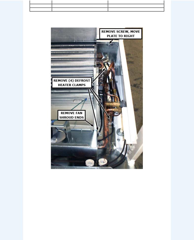
After the coil is exposed, unscrew the four cable clamps at the right end of the coil that hold the elements to the case floor pan. Loosen the closure plates at each end of the coil (photo 1 and photo 2), remove Fan Shroud ends (photo 1 and photo 2) and remove coil support brackets (photo 3).
For orientation, the front leg of the element is located about 1” above the floor pan. The rear leg of the element is located 2” above the floor pan on the original two-piece heaters, and 3” above the floor pan on the later one-piece heater design (photo 6). Install the rear leg of the replacement heater in the same location as the original heater.
With a permanent marker, mark the exact location of the retaining clips on the evaporator coil. Remove the front heater by pulling the clip forward with pliers, working from left to right, until the heater falls to the floor pan (photo 4). After the front element is free from the clips, again using pliers and working from left to right, raise the clips until they are free of the coil (photo 5). The rear element will come up with the clip.
Install the new one-piece, U-shaped element in the reverse order. Start with the rear leg of the new element resting on the top of the coil. Place the retaining clips in the same position they were originally located, and push the clips down using a block of wood to avoid injury from sharp coil fins. Reconnect the new heater leads to the terminal block and brown-wire Klixon. Reseal wire egresses at both ends of the case. If refrigerant lines are adjacent to the left end of the one-piece replacement heater, install Zero Zone part 31-0133, Bracket Defrost Heater Retainer (photo 2).
Heater elements and heater clips are available through the Zero Zone parts department, call (262) 392-1300. The elements are coiled and shipped in a 27” X 30” X 2” cardboard package.
CASE SIZE |
REPLACEMENT DEFROST HEATER KIT PART NUMBERS 3 |
||
6.5" COIL FIN DEPTH 1 |
7.5" COIL FIN DEPTH 2 |
||
|
|||
2-Door |
169-0177-02 |
169-0178-02 |
|

3-Door |
169-0177-03 |
169-0178-03 |
4-Door |
169-0177-04 |
169-0178-04 |
5-Door |
169-0177-05 |
169-0178-05 |
Back to Top
Photo 1 - Right End of Coil
Back to Top
Photo 2 - Left End of Coil
 Loading...