

Page 1
Rear Load
D
D
isplay
Coolers
ZERO ZONE
Zero Zone, Inc. • 110 N. Oakridge Dr. • North Prairie, WI 53153-9792
1-800-247-4496 • FAX: 1-414-392-6450 • www.zero-zone.com
Shop Around
RMCP30 Series
RMCP24 Series
C
CRMA
Certified
INSTALLATION
and
OPERATING INSTRUCTIONS
for
06995M21000129
Page 2

TABLE OF CONTENTS
SUBJECT
GENERAL INFORMATION .............................................................................. 1
INTRODUCTION ........................................................................................................ 1
INSPECTION .............................................................................................................. 1
LOCATION .............................……………................................................................ 1
INSTALLATION .........................................….................................................. 1
LEVELING ................................................................................................................. 1,3
JOINING COOLERS ......................................................…........................................ 3
DRAIN LINE ...............................................…............................................................ 3
CART BUMPER .......................................................................................................... 3
REFRIGERATION ...................................................................................…...... 5
GENERAL ......................................................…........................................................ 5
REFRIGERANT PIPING .........................................................................….................. 5
TEMPERATURE CONTROL ........................................................................................ 5-6
LEAK CHECK-EVACUATION-CHARGING ............................................................... 6
ELECTRICAL ..................................................................................…............. 6
DEFROSTING ................................................................................................. 6
USER INFORMATION .................................................................................... 6
CLEANING ......................................................…...................................................... 6
SHELF LOCATION ..................................................................................................... 6
LANE DIVIDERS …..................................................................................................... 7
SHELF GLIDES …....................................................................................................... 7
PRE CUT SALAD RACK ............................................................................................ 7
FLORAL SHELVES ..................................................................................................... 7
LOADING THE COOLER .......................................................................................... 8
LIGHT SWITCH .......................................................................................................... 8
SERVICE ........................................................................................................ 8
CART BUMPER .......................................................................................................... 8
EVAPORATOR .......................................................................................................... 8
EXPANSION VALVE .................................................................................................. 8
EVAPORATOR FANS ....………................................................................................. 8
LIGHTS ............................................................................................…………………. 9
BALLASTS ..............................................................…......................……….………… 9
ALTERNATE LIGHTING - T8 ..............................................................…...................... 9
CONDENSATE EVAPORATION SYSTEM ...........................................………………. 9
RMCP30, RMCP30RL, RMCP30SA, RMCP24
Page 3

TABLES
TABLE 1 RMCP30/RMCP30RL LINE SIZE R22 ........…………………......…................
TABLE 2 RMCP30SA LINE SIZE R22 ..................…..............………………………......
TABLE 3 RMCP24 LINE SIZE R22 ...........…………....…...............…...........................
FIGURES
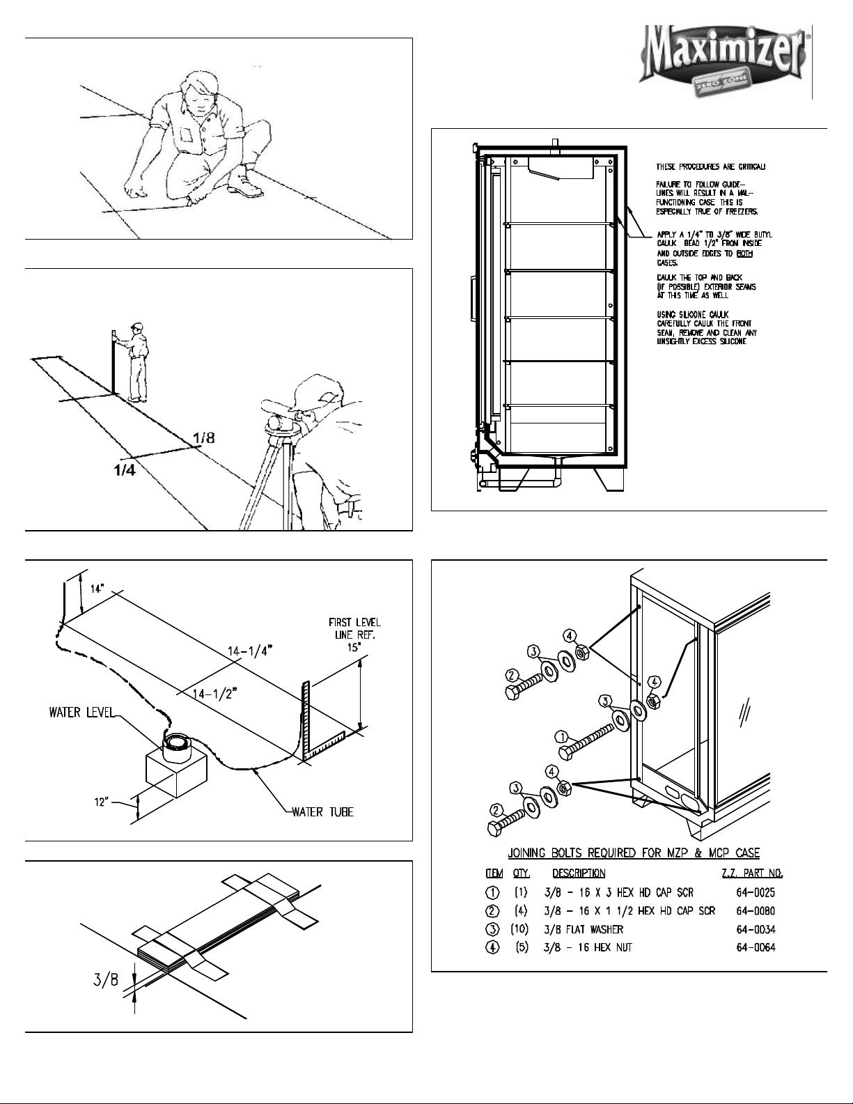
FIGURE 1 LEVELING CASES PRIOR TO JOINING .........................…............….…...
FIGURE 2 CAULKING CASES TO BE JOINED ....……....................…..............……...
FIGURE 3 JOINING 30” DOOR REACH-IN COOLERS .........................…......……..
FIGURE 4 INSTALLING THE CART BUMPER …………………...........................……...
FIGURE 5 JOINING 30” DOOR REAR LOAD OR SHOP AROUND COOLERS ……
FIGURE 6 JOINING 24” DOOR REACH-IN COOLERS .........................…......……..
FIGURE 7 INSTALLING TEE STRIPS ……………………….........................…......……..
FIGURE 8 TEMPERATURE CONTROL SETTINGS ….........................….........…....…...
FIGURE 9 TYPICAL TEMPERATURE CONTROLS ….........................…..............….....
FIGURE 10 LANE DIVIDERS .......………………………………….....................….…...
FIGURE 11 SALAD RACKS .......……………………………...….......................….…...
FIGURE 12 SOCKET DETAIL ......................…………………….......….........................
FIGURE 13 RMCP30 SPECIFICATION SHEET ...............................….........................
FIGURE 14 RMCP30RL SPECIFICATION SHEET ........................................................
FIGURE 15 RMCP30SA SPECIFICATION SHEET .......................................................
FIGURE 16 RMCP24 SPECIFICATION SHEET ................................................…........
FIGURE 17 RMCP30/RMCP24 WIRING DIAGRAM ........................................…....
WARRANTY ................................………………..............................................
RMCP30, RMCP30RL, RMCP30SA, RMCP24
Page 4

GENERAL INFORMATION
Location
Introduction
The information contained in this manual pertains to
the following display coolers: RMCP30, RMCP30RL,
RMCP30SA and RMCP24. These are used for merchandising refrigerated packaged food. The number
30 in the model number designate a case with 30”
wide doors. The number 24 in the model number
indicates 24” wide doors.
These display coolers are designed to operate in an
air-conditioned store where the temperature is maintained at 75°F or lower and the relative humidity is
55% or lower.
RMCP30RL (REAR LOAD)
This case design allows product to be loaded through
solid sliding doors at the rear of the case. The case is
designed to have the back of case built into the wall of
a cooler. The rear doors do not have lamps but are
heated to prevent condensation. Detailed instructions
can be found in the door manufacturer’s instruction
sheet.
Do not locate this equipment where it will be exposed
to the direct rays of the sun or near a source of radiant
heat or airflow.
Be certain that the floor under the installation is of
sufficient strength to prevent sagging. out of level
conditions will result in reduced performance.
Wall cases, and back to back cases, should be positioned to allow a 1 - 4 inch space behind the back of a
unit. This space will allow air to circulate behind the
unit.
INSTALLATION
Leveling (See Figure 1)
Refrigeration equipment must be installed level to
allow efficient operation of the refrigeration coils and
complete drainage of defrost water. Since a level area
is seldom available, the following steps are recommended to insure a level installation.
1. Measure off and mark on floor the exact dimensions of the case line-up. (Check blueprints).
RMCP30SA (SHOP AROUND)
This case design allows product to be shopped from
either side. The evaporator fans face the front of the
case. The main wiring compartment is located behind
the kick plate in the front of the case. If ballasts are
supplied by Zero Zone and not the door manufacturer,
they will be located behind the kick plate.
Inspection
These display coolers were carefully inspected and
properly packed to ensure delivery in the best possible
condition. The equipment should be checked for
damage immediately upon delivery. ALL CLAIMS FOR
DAMAGES MUST BE FILED WITH THE TRANSPORTATION
COMPANY - NOT WITH Zero Zone. The carrier will
supply necessary report and claim forms.
2. Snap a chalk line at the locations for the front and
back positions of the base rails.
3. Mark locations of all joints (front and back).
4. Using a transit, find the highest point along both
base rail position lines. using the high point as a
reference, mark the difference directly on the floor
at each joint (front and back).
5. If a transit is not available, a water level can be
used to mark reference elevation points. Water
levels can be purchased from a contractor supply
house for a minimal cost.
6. A string level can also be used to mark elevation
points. The string level should only be used on
short line-ups to avoid string sag.
RMCP30, RMCP30RL, RMCP30SA, RMCP24
Page 5
Mark floor level differences
Measure and mark exact case
Figure 2: Caulking cases to be joined
Water level elevation points
Shim joints to equal highest points
Figure 3: Joining 30” Door RMCP30 Reach-In Coolers
RMCP30, RMCP30RL, RMCP30SA, RMCP24
Page 6

7. Place the required number of shims (supplied) at
each joint (front and back) to equal the highest
point. Tape all shims in place.
8. Place additional support shims at the center of four
and five door case base rails (front and back).
9. Use a carpenter’s level to check installation as you
go. The case should be level from front to back and
side to side. Install the case at the highest point
first, if part of a line-up.
Joining Coolers
These reach-In coolers have been engineered for
continuous display. This means that any number of
cases can be joined together to create a display of any
desired length. Reach-In coolers are built on permanent steel skids to promote easy installation. The
cases can be moved on pipe rollers or with a Johnson
Bar. The ends of the case are protected with a removable steel plate.
Drain Line
Condensate water drains from the evaporator through
a plastic hose mounted at the rear of the case. The
tubing should be free of kinks and dirt so water drains
freely. The case drain is located at the center of the
cooler in the floor pan. The 1 inch PVC drain outlet is
located at the center front of the cooler behind the kick
plate.
The tee, drain trap, and plug are supplied standard
with the case. Install a tee to the outlet pipe and a PVC
drain trap to the tee. Plug the open end of the tee
using the clean-out plug supplied with the drain trap
kit. The drain line must be pitched away from the case
a minimum of 1/4 inch per foot.
Cart Bumper
The cart bumper should be installed at the bottom
front of the case. (See Figure 4) The assembly is
adjustable to compensate for uneven floors.
To install Reach-Ins, perform the following steps:
1. Set the first Reach-In into the desired position and
level it. Run a 3/8-inch diameter bead of Butyl caulk
½ inch in from both the inner and outer surfaces of
the case end. (See Figure 2)
2. Push the second Reach-In against the end of the
first. Level the second Reach-In. See Figure 3 for
30” Door cases; Figure 5 for 30” Door Reach-In Rear
Load and Shop Around cases; and Figure 6 for 24”
Door Reach-In Coolers. Install tee strips between
the door frames at case joints on 30” door cases
(See Figure 7). Use the special screws and nuts
provided.
3. Start the joining bolts, but do not tighten them.
Begin tightening the bolts at the top rear, working
down the back of the case and up the front making
sure that the front seams are flush.
Center and hook the bumper assembly on the hanger
provided.
In continuous line-ups, place a kick plate joint strip at
each joint. On case ends, lineup the end kick plate
with the front mounting holes. Fasten the rear of the
end kick plate to the case using self drilling (TECH)
screws.
Slide the front kick plate behind the bumper assembly
and in front of the end kick plate or kick plate joint strip.
Install three screws (two screws on 2-door only) to hold
the kick plate and bumper in place. The screws attach
the kickplate to a bracket with a speed nut
(timmerman clip).
A bumper joint strip can be installed over the bumper
at the joints. This is standard on the Euro Style
bumper.
RMCP30, RMCP30RL, RMCP30SA, RMCP24
Page 7
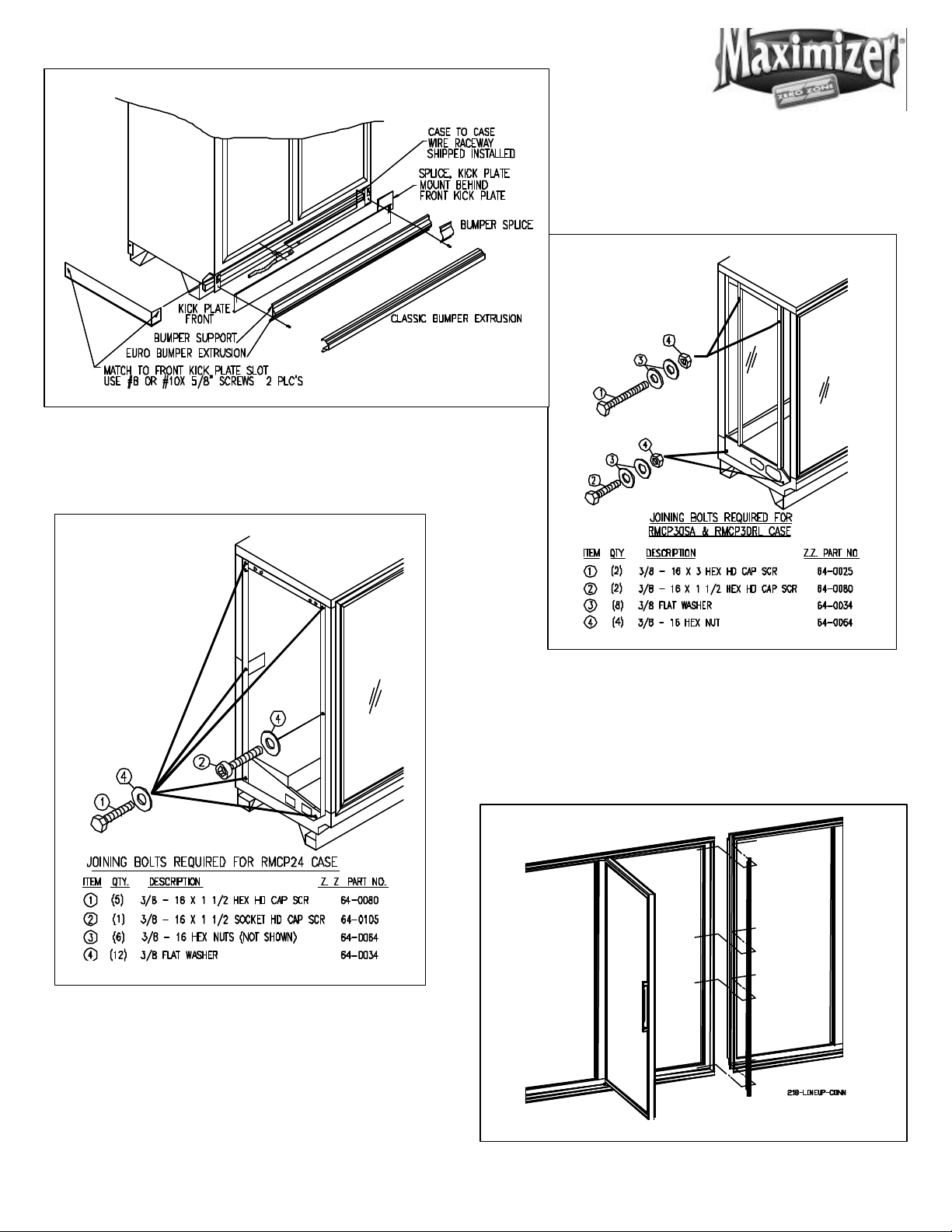
Figure 4: Installing The Cart Bumper
Figure 6: Joining 24” Door Reach-In Coolers
Figure 5: Joining 30” Door Rear Load or Shop
Around Reach-In Coolers
Figure 7: Installing Tee Strips
RMCP30, RMCP30RL, RMCP30SA, RMCP24
Page 8
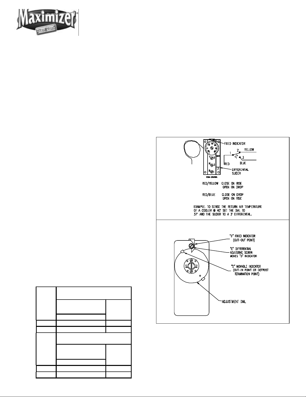
TEMP.
TIME CLOCK DEFROST
TEMP.
R-22
64
40
OFF CYCLE DEFROST
PRODUCT 41° F TO 37° F
4268R-22
Figure 8: Temperature Control
REFRIGERATION
Temperature Control
General
Unless otherwise specified, the liquid and suction
connections are made on top of the case. (Figures 13-
16.) Alternate locations are out the back of case. After
connections are made, the refrigeration access hole in
the cooler must be sealed completely with aerosoldispensed Urethane insulation or equivalent.
Refrigerant Piping
Correct refrigeration line sizing and installation is
essential for proper system operation. The following
tables (Tables 1 -3) list R-22 line sizes for different
combinations of coolers. A P-trap must be installed at
the bottom of all vertical suction risers.
The compressor should be installed as close as possible to the coolers to reduce pressure drop. If the
compressor is located above the cooler, use one size
smaller tube for the suction tube riser only and install a
shallow trap at the bottom of the riser. Use a flexible
connection (vibration eliminator) between the suction
line and compressor.
A low pressure or temperature control located to
sense return air can be used to control cooler temperature. The control should be selected with adequate contact capacity for the switching load. In rack
systems, an evaporator pressure-regulating valve may
be used to control the evaporating temperature.
The settings (See Figure 8) are approximate due to
variations in gauge accuracy, differences in compressor efficiency, and line pressure drop. These should
be adjusted as store or stocking conditions change.
The suction and liquid lines may be taped together to
form an external heat exchanger. Insulate the tubing
for at least 20 feet from the cooler outlet.
A liquid line drier should be installed. Install a moisture indicating sight glass at the outlet end of the drier.
PRODUCT 41° F TO 37° F
Pressure
(psig)
Cut In 37° F
Cut Out 33° F
Pressure
(psig)
Cut In 40° F
Cut Out 34° F
RETURN
AIR
RETURN
AIR
Figure 9: Typical Temperature Controls
RMCP30, RMCP30RL, RMCP30SA, RMCP24
Page 9

Temperature Control Adjustment
When factory installed, the temperature control is
located on top of the cooler. The sensing bulb is
located under the coil cover in front of the coil.
(Figure 9 shows typical temperature controls).
Leak Check-Evacuation-Charging
After all of the refrigeration piping and system
components have been assembled, the entire
system must be pressurized and checked for leaks.
Use nitrogen and refrigerant vapor to check for
leaks. A Halide leak detector or an electronic leak
detector is recommended.
If the system is sealed, evacuate with a high
vacuum pump. Triple evacuation to a minimum of
500 microns and nitrogen sweep is recommended.
After the system has been thoroughly evacuated of
all moisture and non-condensable gas, charge the
system with the proper refrigerant, using “hi-side/
low-side” charging techniques.
The fan circuit is energized at all times. The light and
anti-condensate circuit may be cycled off during
defrost. If a time clock is used, it is in operation at all
times.
Note: All wiring must comply with the National Electrical Code and all local codes.
DEFROSTING
Periodic defrosting to keep the coil free of frost is
accomplished either automatically by a time clock or
with compressor off cycle defrost. The most reliable
defrost system uses a time clock that turns off the
refrigeration cycle once per day for 60 minutes. A time
clock can be purchased from Zero Zone or from a
local refrigeration supply house.
When only OFF cycle defrost is used, the compressor
must be sized large enough to allow for periodic off
cycles. When the compressor shuts off, the evaporator
fans continue to run. This allows the coil to defrost.
The cut-in set point for the compressor should be not
lower than 40°F when OFF cycle defrost is used.
ELECTRICAL
Figure 17 shows the typical wiring diagram for a
cooler. Each case is provided with a wiring diagram
located in the electric box that shows the exact
wiring of the case.
External wiring should be sized according to the
amperage rating stamped on the serial plate. The
serial plate is located on the ceiling inside the lefthand door. Typical electrical values are shown in
Figures 13-16. All internal wiring has been done at
the factory, and has been terminated in the electrical compartment located behind the kick rail at the
right end of the case. The temperature control
mounted on top of the case is not wired. A terminal
block has been used to simplify field connections.
USER INFORMATION
Cleaning
The cooler should be thoroughly cleaned before startup and routinely thereafter to maintain a clean appearance. Use mild detergent and warm water (never
an abrasive cleaner) to wipe out the inside of the
cooler. Wash down all glass doors with glass cleaner.
The cooler will remain bright and sparkling with just a
few minutes of cleaning each week. The case drain
should be regularly cleared of debris and price tags
Note: Do not use high-pressure water or steam to
clean the interior.
Shelf Location
The shelves are adjustable in 1/2-inch increments.
They may be located in any position for best display
RMCP30, RMCP30RL, RMCP30SA, RMCP24
Page 10

Figure 10: Lane Dividers
Figure 11: Salad Rack
The rack is installed as follows:
advantage. due to the air discharge arrangement, it is
suggested that the uppermost shelf be placed 11
inches down from the ceiling. Place the remaining
shelves approximately 10 1/2 inches apart.
Be sure shelf clips or brackets are completely
seated before installing the shelf.
Lane Dividers (RMCP30 Only)
Lane dividers with 2-7/8 inch, 3-1/4 inch, 3-3/4 inch, or
4-3/4 inch wide lanes are available for use on the
shelves. The rear of the lane divider has the shelf
hooks inset from the end. The lane divider is installed
by hooking the rear hooks under the large shelf wire
(See Figure 10). Flex the lane divider and hook the wire
under the large front shelf wire.
Shelf Glides (RMCP30 Only)
Shelf glides are available for use with lane dividers.
This helps the product gravity feed to the front of the
case.
1. Set the rack on top of the shelf.
2. Rotate the rack 45 degrees to the side.
3. Slide both rear feet under the shelf wires.
4. Rotate the salad rack back to the original position
while keeping the rear feet under the wires.
5. Gently squeeze the front of the rack and slide the
two feet between the shelf wires (See Figure 11.
Floral Shelves (RMCP30 Only)
Glass cantilever floral shelves are available. The
shelves rest on special extra wide shelf brackets.
Cantilever floral bucket shelves are also available. The
bucket shelf bracket is adjustable to allow for shelf
tilting. Before attempting to adjust the shelf bracket,
follow these steps:
1. Remove the shelf.
Pre Cut Salad Rack
The rear of the rack has two feet that slip under the
shelf wires. The rear of the rack also has a raised wire
stop. The stop is used to provide an air gap between
the product and rear wall.
2. Remove the set screw from the side of the bracket.
3. Rotate the bracket to the new position.
4. Install the set screw.
Cantilever shelf standards are factory installed and
must be ordered with a new case.
RMCP30, RMCP30RL, RMCP30SA, RMCP24
Page 11

Loading the Cooler
The cooler may be loaded with merchandise after it
has been operated for at least 24 hours with correct
case temperature and proper control operation. While
loading the shelves, leave at least 1 1/2 inch between
the top of the merchandise and the shelf above it so
the customer can remove the merchandise. Leave a 1
1/2-inch air gap at the rear of the case. This allows
cool air to travel down the back of the product and
return to the evaporator at the front of the case. The 1
1/2-inch space allows an air curtain on the top of the
product.
Light Switch
The light switch is located on the mullion or upper right
corner of the doorframe. Always turn the lights off
when replacing lamps.
SERVICE
Cart Bumper
Loosen two screws on the underside of the coil cover
until the forward edge drops down exposing the
evaporator coil and fan assemblies.
While supporting the cover, unplug the fan electrical
connection from main coil housing.
Expansion Valve
A thermostatic expansion valve with a “C” charge,
adjustable superheat and thermal bulb is mounted to
the evaporator coil. Under certain conditions, it may
be necessary to adjust the superheat setting for maximum coil effectiveness. Typical superheat settings are
between 10°F and 15°F. To adjust the expansion valve,
remove the coil cover. Remove the cap from the
bottom of the valve. When looking at the valve stem
end, turn the valve stem counterclockwise to decrease
superheat. Turn the valve stem clockwise to increase
super heat. Measure the suction line temperature at
the expansion valve-sensing bulb and compare it to
the suction temperature corresponding to the saturated pressure. Make sure that line pressure drop is
taken into account.
The cart bumper must be removed to gain access to
the drain connection and electrical connection. Disassemble the bumper and black kick plate by removing
the 2 or 3 metal screws located in the kick plate. The
bumper assembly can be lifted up and removed from
the case. The kick plate can be removed, exposing
the electrical connection and drain outlet. (Figure 4
shows the bumper assembly)
Evaporator
The evaporator coil, located at the ceiling of the cooler,
is factory assembled with an expansion valve. To
inspect the coil, the coil cover can be removed as
follows:
Turn the valve stem only 1/4 turn at a time and allow
sufficient time (20 to 30 minutes) for the valve to settle
before making any further adjustments. Replace the
valve stem cap after the valve super-heat has been
adjusted. BE CERTAIN THE VALVE STEM CAP IS WIPED
DRY FIRST.
! CAUTION !
DISCONNECT POWER TO THE CASE BEFORE
SERVICING ELECTRICAL COMPONENTS
Evaporator Fans
Air is circulated throughout the cooler with shaft down,
115-volt medium temperature fan motors. These
motors must be operating at all times. The fans are
mounted on the evaporator coil cover. To service the
fans, they are accessed by removal of the coil cover as
described under SERVICE/EVAPORATOR.
RMCP30, RMCP30RL, RMCP30SA, RMCP24
Page 12

Lights
high output 800 milliamp lamps are standard. To
ensure maximum component life, always replace with
800 milliamp lamps. Use retainer clips and lamp
shields.
To change a lamp, turn off the light switch and remove
the retainer clip located between the top socket and
end cap. Carefully push the lamp up into the springloaded lamp socket to allow the lamp to be removed
from the bottom socket. (See Figure 12.) Remove the
end caps and shield. All lamps must use end caps
and shields.
the shelves. The lens must be removed to access the
lamp. Ardco’s lamp may be removed by turning it 90
degrees and sliding the lamp pins out of the lamp
socket slot. The lens must be installed over the lamp.
Anthony’s lamp is removed by sliding the end caps off
of the lamp. Detailed information is contained in the
door instruction booklet.
Condensate Evaporation System
Zero Zone remote cases can be equipped with an
automatic condensate evaporation system. The
system uses a pump and drain pan located behind
the kick plate and a condensate evaporator pan
mounted on the top of the case.
Figure 12: Socket Detail
Condensate water and any liquid spilled in the case
drain out into the drain pan. The pump is equipped
with a float that turns the pump on when there is a
sufficient liquid level. Liquid is pumped through a
plastic hose through a check valve and into the condensate-evaporating pan. The evaporating pan is
equipped with a heater and a float switch to turn on
when the heater is submerged in liquid. When the
heater is energized the pan will be extremely hot and
should not be touched.
The pump and condensate pan should be cleaned
regularly. Any spilled product should be cleaned to
prevent odors.
Ballast
Zero Zone cooler ballasts are located either behind
the kick plate or in the door mullions.
Alternate Lighting -T8
T-8 lighting is standard on the 30” door case and
optional on the 24” door coolers. Many door manufacturers provide premium lighting systems. These
systems use a lens to direct light output evenly across
RMCP30, RMCP30RL, RMCP30SA, RMCP24
Page 13

BTU/HR
NO. OF
Table 1
RMZC30, RMZP30, RMZP24
REMOTE REACH-IN COOLER W/ 30" X 63" DOORS
MODEL RMCP30 & RMCP30RL
REFRIGERANT R-22 @ 20° F EVAPORATOR
FREEZER
DOORS
10 (2) 5-DR 25'-11 3/4" 11,250 3/8 3/8 3/8 5/8 7/8 7/8
11 (1) 3-DR & (2) 4-DR 28'-7 3/8" 12,375 3/8 3/8 3/8 7/8 7/8 7/8
12 (3) 4-DR 31'-1 13/16" 13,500 3/8 3/8 3/8 7/8 7/8 7/8
13 (2) 4-DR & (1) 5-DR 33'-8 1/4" 14,625 3/8 3/8 3/8 7/8 7/8 7/8
14 (1) 4-DR & (2) 5-DR 36'-2 11/16" 15,750 3/8 3/8 3/8 7/8 7/8 7/8
15 (3) 5-DR 38'-9 1/8" 16,875 3/8 3/8 1/2 7/8 7/8 7/8
16 (4) 4-DR 41'-4 3/4" 18,000 3/8 3/8 1/2 7/8 7/8 1 1/8
17 (3) 4-DR & (1) 5-DR 43'-11 3/16" 19,125 3/8 3/8 1/2 7/8 7/8 1 1/8
18 (2) 4-DR & (2) 5-DR 46'-5 5/8" 20,250 3/8 3/8 1/2 7/8 7/8 1 1/8
19 (1) 4-DR & (3) 5-DR 49'-1 1/16" 21,375 3/8 1/2 1/2 7/8 7/8 1 1/8
20 (4) 5-DR 51'-6 1/2" 22,500 3/8 1/2 1/2 7/8 1 1/8 1 1/8
21 (4) 4-DR & (1) 5-DR 54'-2 1/8" 23,625 3/8 1/2 1/2 7/8 1 1/8 1 1/8
22 (3) 4-DR & (2) 5-DR 56'-8 9/16" 24,750 3/8 1/2 1/2 7/8 1 1/8 1 1/8
23 (2) 4-DR & (3) 5-DR 59'-3" 25,875 3/8 1/2 1/2 7/8 1 1/8 1 1/8
24 (1) 4-DR & (4) 5-DR 61'-9 7/16" 27,000 3/8 1/2 1/2 7/8 1 1/8 1 1/8
25 (5) 5-DR 64'-3 7/8" 28,125 3/8 1/2 1/2 7/8 1 1/8 1 1/8
26 (4) 4-DR & (2) 5-DR 66'-11 1/2" 29,250 1/2 1/2 1/2 7/8 1 1/8 1 1/8
27 (3) 4-DR & (3) 5-DR 69'-5 15/16" 30,375 1/2 1/2 1/2 7/8 1 1/8 1 1/8
28 (2) 4-DR & (4) 5-DR 72'-3/8" 31,500 1/2 1/2 5/8 7/8 1 1/8 1 1/8
29 (1) 4-DR & (5) 5-DR 74'-6 13/16" 32,625 1/2 1/2 5/8 1 1/8 1 1/8 1 1/8
30 (6) 5-DR 77'-1 1/4" 33,750 1/2 1/2 5/8 1 1/8 1 1/8 1 1/8
NOTE: BTU/HR RATING BASED ON 800 MA T-12 LIGHTING AND PARALLEL RACK SYSTEM. MULTIPLY BY 1.04
FOR CONVENTIONAL SYSTEM. DEDUCT 30 BTU/DOOR FOR T-8 ELECTRONIC LIGHTING SYSTEM. CASES
DESIGNED TO OPERATE IN AN AMBIENT OF 75°F OR LOWER AND RELATIVE HUMIDITY O
COMBINATIONS
2 (1) 2-DR 5'-7 1/16" 2,735 3/8 3/8 3/8 1/2 1/2 1/2
3 (1) 3-DR 8'-1 1/2" 3,705 3/8 3/8 3/8 1/2 1/2 5/8
4 (1) 4-DR 10'-7 15/16" 4,650 3/8 3/8 3/8 1/2 5/8 5/8
5 (1) 5-DR 13'-2 3/8" 5,625 3/8 3/8 3/8 1/2 5/8 5/8
6 (2) 3-DR 15'-10" 6,750 3/8 3/8 3/8 5/8 5/8 7/8
7 (1) 3-DR & (1) 4-DR 18'-4 7/16" 7,875 3/8 3/8 3/8 5/8 5/8 7/8
8 (2) 4-DR 20'-10 7/8" 9,000 3/8 3/8 3/8 5/8 7/8 7/8
9 (1) 4-DR & (1) 5-DR 23'-5 5/16" 10,125 3/8 3/8 3/8 5/8 7/8 7/8
TOTAL
LENGTH
W/ENDS
RECOMMENDED
LIQUID LINE SIZES
EQUIVALENT LENGTH, FEET
50 100 150 50 100 150
RECOMMENDED
SUCTION LINE SIZES
EQUIVALENT LENGTH, FEET
RMCP30, RMCP30RL, RMCP30SA, RMCP24
RMZC30, RMZP30, RMZP24
Page 14

NO. OF
BTU/HR
Table 2
REMOTE REACH-IN COOLER W/ 30" X 63" DOORS
MODEL RMCP30SA
REFRIGERANT R-22 @ 20° F EVAPORATOR
FREEZER
DOORS
10 (2) 5-DR 25'-11 3/4" 19,690 3/8 3/8 1/2 7/8 7/8 1 1/8
11 (1) 3-DR & (2) 4-DR 28'-7 3/8" 21,659 3/8 1/2 1/2 7/8 7/8 1 1/8
12 (3) 4-DR 31'-1 13/16" 23,628 3/8 1/2 1/2 7/8 1 1/8 1 1/8
13 (2) 4-DR & (1) 5-DR 33'-8 1/4" 25,597 3/8 1/2 1/2 7/8 1 1/8 1 1/8
14 (1) 4-DR & (2) 5-DR 36'-2 11/16" 27,566 3/8 1/2 1/2 7/8 1 1/8 1 1/8
15 (3) 5-DR 38'-9 1/8" 29,535 3/8 1/2 1/2 7/8 1 1/8 1 1/8
16 (4) 4-DR 41'-4 3/4" 31,504 1/2 1/2 5/8 7/8 1 1/8 1 1/8
17 (3) 4-DR & (1) 5-DR 43'-11 3/16" 33,473 1/2 1/2 5/8 1 1/8 1 1/8 1 1/8
18 (2) 4-DR & (2) 5-DR 46'-5 5/8" 35,442 1/2 1/2 5/8 1 1/8 1 1/8 1 3/8
19 (1) 4-DR & (3) 5-DR 49'-1 1/16" 37,411 1/2 1/2 5/8 1 1/8 1 1/8 1 3/8
20 (4) 5-DR 51'-6 1/2" 39,380 1/2 5/8 5/8 1 1/8 1 1/8 1 3/8
21 (4) 4-DR & (1) 5-DR 54'-2 1/8" 41,349 1/2 5/8 5/8 1 1/8 1 1/8 1 3/8
22 (3) 4-DR & (2) 5-DR 56'-8 9/16" 43,318 1/2 5/8 5/8 1 1/8 1 1/8 1 3/8
23 (2) 4-DR & (3) 5-DR 59'-3" 45,287 1/2 5/8 5/8 1 1/8 1 3/8 1 3/8
24 (1) 4-DR & (4) 5-DR 61'-9 7/16" 47,256 1/2 5/8 5/8 1 1/8 1 3/8 1 3/8
25 (5) 5-DR 64'-3 7/8" 49,225 1/2 5/8 5/8 1 1/8 1 3/8 1 3/8
26 (4) 4-DR & (2) 5-DR 66'-11 1/2" 51,194 1/2 5/8 5/8 1 1/8 1 3/8 1 3/8
27 (3) 4-DR & (3) 5-DR 69'-5 15/16" 53,163 1/2 5/8 5/8 1 1/8 1 3/8 1 3/8
28 (2) 4-DR & (4) 5-DR 72'-3/8" 55,132 1/2 5/8 5/8 1 1/8 1 3/8 1 3/8
29 (1) 4-DR & (5) 5-DR 74'-6 13/16" 57,101 1/2 5/8 5/8 1 1/8 1 3/8 1 3/8
30 (6) 5-DR 77'-1 1/4" 59,070 5/8 5/8 7/8 1 1/8 1 3/8 1 3/8
COMBINATIONS
2 (1) 2-DR 5'-7 1/16" 4,785 3/8 3/8 3/8 1/2 5/8 5/8
3 (1) 3-DR 8'-1 1/2" 6,485 3/8 3/8 3/8 5/8 5/8 5/8
4 (1) 4-DR 10'-7 15/16" 8,140 3/8 3/8 3/8 5/8 5/8 7/8
5 (1) 5-DR 13'-2 3/8" 9,845 3/8 3/8 3/8 5/8 7/8 7/8
6 (2) 3-DR 15'-10" 11,814 3/8 3/8 3/8 5/8 7/8 7/8
7 (1) 3-DR & (1) 4-DR 18'-4 7/16" 13,783 3/8 3/8 3/8 7/8 7/8 7/8
8 (2) 4-DR 20'-10 7/8" 15,752 3/8 3/8 3/8 7/8 7/8 7/8
9 (1) 4-DR & (1) 5-DR 23'-5 5/16" 17,721 3/8 3/8 1/2 7/8 7/8 1 1/8
TOTAL
LENGTH
W/ENDS
RECOMMENDED
LIQUID LINE SIZES
EQUIVALENT LENGTH, FEET
50 100 150 50 100 150
RECOMMENDED
SUCTION LINE SIZES
EQUIVALENT LENGTH, FEET
NOTE: BTU/HR RATING BASED ON 800 MA T-12 LIGHTING AND PARALLEL RACK SYSTEM. MULTIPLY
BY 1.04 FOR CONVENTIONAL SYSTEM. DEDUCT 30 BTU/DOOR FOR T-8 ELECTRONIC LIGHTING
SYSTEM. CASES DESIGNED TO OPERATE IN AN AMBIENT OF 75°F OR LOWER AND RELATIVE
HUMIDITY O
RMZC30, RMZP30, RMZP24
RMCP30, RMCP30RL, RMCP30SA, RMCP24
RMZC30, RMZP30, RMZP24
Page 15

BTU/HR
NO. OF
Table 3
REMOTE REACH-IN COOLER W/ 24" X 63" DOORS
MODEL RMCP24
REFRIGERANT R-22 @ 20° F EVAPORATOR
FREEZER
DOORS
COMBINATIONS
2 (1) 2-DR 4'-8 7/8" 2,515 3/8 3/8 3/8 1/2 1/2 1/2
3 (1) 3-DR 6'-8 5/8" 3,355 3/8 3/8 3/8 1/2 1/2 1/2
4 (1) 4-DR 8'-8 3/8" 4,180 3/8 3/8 3/8 1/2 1/2 5/8
5 (1) 5-DR 10'-8 1/8" 4,965 3/8 3/8 3/8 1/2 5/8 5/8
6 (2) 3-DR 13'-1/4" 5,958 3/8 3/8 3/8 1/2 5/8 5/8
7 (1) 3-DR & (1) 4-DR 15'- 0" 6,951 3/8 3/8 3/8 5/8 5/8 7/8
8 (2) 4-DR 16'-11 3/4" 7,944 3/8 3/8 3/8 5/8 5/8 7/8
9 (1) 4-DR & (1) 5-DR 18'-11 1/2" 8,937 3/8 3/8 3/8 5/8 7/8 7/8
10 (2) 5-DR 20'-11 1/4" 9,930 3/8 3/8 3/8 5/8 7/8 7/8
11 (1) 3-DR & (2) 4-DR 22'-10 3/8" 10,923 3/8 3/8 3/8 5/8 7/8 7/8
12 (3) 4-DR 25'-3 1/4" 11,916 3/8 3/8 3/8 5/8 7/8 7/8
13 (2) 4-DR & (1) 5-DR 27'-2 7/8" 12,909 3/8 3/8 3/8 7/8 7/8 7/8
14 (1) 4-DR & (2) 5-DR 29'-2 5/8" 13,902 3/8 3/8 3/8 7/8 7/8 7/8
15 (3) 5-DR 31'-2 3/8" 14,895 3/8 3/8 3/8 7/8 7/8 7/8
16 (4) 4-DR 33'-6 1/2" 15,888 3/8 3/8 3/8 7/8 7/8 7/8
17 (3) 4-DR & (1) 5-DR 35'-6 1/4" 16,881 3/8 3/8 1/2 7/8 7/8 7/8
18 (2) 4-DR & (2) 5-DR 37'-6" 17,874 3/8 3/8 1/2 7/8 7/8 1 1/8
19 (1) 4-DR & (3) 5-DR 39'-5 3/4" 18,867 3/8 3/8 1/2 7/8 7/8 1 1/8
20 (4) 5-DR 41'-1/2" 19,860 3/8 3/8 1/2 7/8 7/8 1 1/8
21 (4) 4-DR & (1) 5-DR 43'-9 5/8" 20,853 3/8 1/2 1/2 7/8 7/8 1 1/8
22 (3) 4-DR & (2) 5-DR 45'-9 3/8" 21,846 3/8 1/2 1/2 7/8 1 1/8 1 1/8
23 (2) 4-DR & (3) 5-DR 47'-9 1/8" 22,839 3/8 1/2 1/2 7/8 1 1/8 1 1/8
24 (1) 4-DR & (4) 5-DR 49'-8 7/8" 23,832 3/8 1/2 1/2 7/8 1 1/8 1 1/8
25 (5) 5-DR 51'-8 5/8" 24,825 3/8 1/2 1/2 7/8 1 1/8 1 1/8
26 (4) 4-DR & (2) 5-DR 54'-3/4" 25,818 3/8 1/2 1/2 7/8 1 1/8 1 1/8
27 (3) 4-DR & (3) 5-DR 56'-1/2" 26,811 3/8 1/2 1/2 7/8 1 1/8 1 1/8
28 (2) 4-DR & (4) 5-DR 58'-1/4" 27,804 3/8 1/2 1/2 7/8 1 1/8 1 1/8
29 (1) 4-DR & (5) 5-DR 60'-0" 28,797 3/8 1/2 1/2 7/8 1 1/8 1 1/8
30 (6) 5-DR 61'-11 3/4" 29,790 3/8 1/2 1/2 7/8 1 1/8 1 1/8
TOTAL
LENGTH
W/ENDS
RECOMMENDED
LIQUID LINE SIZES
EQUIVALENT LENGTH, FEET
50 100 150 50 100 150
RECOMMENDED
SUCTION LINE SIZES
EQUIVALENT LENGTH, FEET
NOTE: BTU/HR RATING BASED ON 800 MA T-12 LIGHTING AND PARALLEL RACK SYSTEM. MULTIPLY
BY 1.04 FOR CONVENTIONAL SYSTEM. DEDUCT 30 BTU/DOOR FOR T-8 ELECTRONIC LIGHTING
SYSTEM. CASES DESIGNED TO OPERATE IN AN AMBIENT OF 75°F OR LOWER AND RELATIVE
HUMIDITY O
RMZC30, RMZP30, RMZP24
RMZC30, RMZP30, RMZP24
RMZC30, RMZP30, RMZP24
RMCP30, RMCP30RL, RMCP30SA, RMCP24
RMZC30, RMZP30, RMZP24
Page 16

PRELIMINARY
RMCP30 SPECIFICATION SHEET
Front View
Top View
Shown in Section
5RMCP30
* NOTE: CASE DIMENSIONS SHOWN REFLECT STANDARD 4-1/2” HIGH BASES
DIMENSIONS SHOWN IN (PARENTHESIS) REFLECT 3-1/2” BASES.
Zero Zone Inc. l 110 N. Oakridge Dr.
North Prairie, WI 53153-9792
1-800-247-4496 l FAX: 1-262-392-6450
www.zero-zone.com
Side View
All specifications are subject to change without notice.
RMCP30, RMCP30RL, RMCP30SA, RMCP24
Page 17

RMCP30 SPECIFICATION SHEET
CUBIC FEET
SQ. FT.
CUBIC FT.
SINGLE END WEIGHT: 54#
0.43
0.9502.10
0.86
1.1203.06
1.29
1.1803.91
1.65
2.4
0.54
0.3601.16
0.81
0.4401.64
1.35
0.602.6
OF 37°F TO 41°F WITH 20°F EVAPORATOR
DOORS
BTU/HR
5
5625
RACK SYSTEM. MULTIPLY BY 1.04 FOR CONVENTIONAL SYSTEM.
5RMCP30
MODEL NUMBER
4RMCP30
CONNECTIONS
ELECTRICAL CONNECTION (B) &
DRAIN (C) LOCATION SCHEDULE
B C
2RMCP30
3RMCP30
REFRIGERATION LOCATION SCHEDULE
A
2RMCP30 14 3/8 OD 5/8 OD
3RMCP30 23 3/8 OD 5/8 OD
4RMCP30 37 3/8 OD 5/8 OD
5RMCP30 26 3/8 OD 5/8 OD
48 5/8 31
79 1/16 46 1/4
109 1/2 61 1/2
139 15/16 76 11/16
INLET SUCTION
PRELIMINARY
RMCP30 CAPACITY
SPECIFICATIONS
SHELVING
CASE
SIZE
29-5/8X 26"
GROSS
2 53.50 66.0 575
3 80.25 98.3 873
4 107.00 130.6 1128
5 133.75 163.0 1440
WEIGHT BASED ON UNCRATED CASES
WITHOUT ENDS, AND FULLY SHELVED.
CAPACITIES
GROSS
WEIGHT*
POUNDS
ELECTRICAL SPECIFICATIONS BY DOOR MANUFACTURER
MODEL NUMBER
FANS
AMPS
T-12
LIGHT
AMPS
ONE
END*
T-12
LIGHT
AMPS
BOTH
ENDS
T-8 LIGHT
AMPS
STD.
DOOR
MULLION FRAME
FRAMELESS
DOOR
TOTAL
FRAME
MULLION
STD.
DOOR
ANTHONY DOORS
2RMCP30 2.4 1.65 2.4 1.45
3RMCP30 3.2 2.4 3.3 1.94
4RMCP30 4 3.3 4.05 2.42
5RMCP30 4.8 4.05 4.8 2.91 1.8 1.72 1.41 0 4.93
0.72
1.08
1.44
ARDCO DOORS
2RMCP30
3RMCP30 3.2
4RMCP30 4 3.3 4.05 3.06 0.52 1.08 0.53 0 2.13
5RMCP30 4.8
# OF
2 2735
3 3705
4 4650
2.4
2.4 3.3 2.34 0.39
4.05 4.8 3.51 0.65
* STANDARD FOR CASE IN A LINE-UP
VOLTAGE: 115 VOLTS 1 PHASE 60 HZ.
BTU/HR ENERGY REQUIREMENTS: FOR PRODUCT TEMPERATURE
BTU/HR RATING BASED ON 800 MA T-12 LIGHTING AND PARALLEL
CASE DESIGNED TO OPERATE IN AN AMBIENT OF 75°F OR
1.89 0.26
LOWER
AND RELATIVE HUMIDITY OF 55% OR LOWER
Zero Zone Inc. l 110 N. Oakridge Dr.
North Prairie, WI 53153-9792
1-800-247-4496 l FAX: 1-262-392-6450
www.zero-zone.com
All specifications are subject to change without notice.
RMCP30, RMCP30RL, RMCP30SA, RMCP24
Page 18

Figure 14
PRELIMINARY
RMCP30RL SPECIFICATION SHEET
Front View
Top View
Shown in Section
5RMCP30RL
* NOTE: CASE DIMENSIONS SHOWN REFLECT STANDARD 4-1/2” HIGH BASES
DIMENSIONS SHOWN IN (PARENTHESIS) REFLECT 3-1/2” BASES.
Zero Zone Inc. l 110 N. Oakridge Dr.
North Prairie, WI 53153-9792
1-800-247-4496 l FAX: 1-262-392-6450
www.zero-zone.com
Side View
All specifications are subject to change without notice.
RMCP30, RMCP30RL, RMCP30SA, RMCP24
Page 19

CUBIC FEET
SQ. FT.
CUBIC FT.
SINGLE END WEIGHT: 54#
ANTHONY DOORS
0.43
0.9502.10
0.86
1.1203.06
ARDCO DOORS
1.08
0.5302.13
1.35
0.602.6
OF 37°F TO 41°F WITH 20°F EVAPORATOR
5RMCP30RL
MODEL NUMBER
4RMCP30RL
Figure 14
PRELIMINARY
RMCP30RL SPECIFICATION SHEET
ELECTRICAL CONNECTION (B) &
DRAIN (C) LOCATION SCHEDULE
B C
2RMCP30RL
3RMCP30RL
A D E
13 11/16 - 18 5/8 3/8 OD 5/8 OD
21 7/8 - 18 1/2 3/8 OD 5/8 OD
37 1/16 - 17 3/8 3/8 OD 5/8 OD
25 11/16 67 3/8 18 5/8 3/8 OD 5/8 OD
MODEL NUMBER
48 5/8 31
79 1/16 46 1/4
109 1/2 61 1/2
139 15/16 76 11/16
CONNECTIONS
INLET SUCTION
ELECTRICAL SPECIFICATIONS BY DOOR MANUFACTURER
FANS
AMPS
T-12
LIGHT
AMPS
ONE
END*
T-12
LIGHT
AMPS
BOTH
ENDS
T-8 LIGHT
AMPS
RMCP30RL CAPACITY
SPECIFICATIONS
SHELVING
CASE
STD.
DOOR
29-5/8X 23-1/2"
SIZE
2 48.3 59.6 575
3 72.5 88.8 873
4 96.6 118.1 1128
5 120.8 147.3 1440
WEIGHT BASED ON UNCRATED CASES WITHOUT
MULLION FRAME
GROSS
ENDS, AND FULLY SHELVED.
CAPACITIES
GROSS
FRAMELESS
DOOR
WEIGHT*
POUNDS
TOTAL
FRAME
MULLION
STD.
DOOR
2RMCP30RL 2.4 1.65 2.4 1.45
3RMCP30RL 3.2 2.4 3.3 1.94
4RMCP30RL 4 3.3 4.05 2.42 1.44 1.29 1.18 0 3.91
5RMCP30RL 4.8 4.05 4.8 2.91
2RMCP30RL 2.4 1.65 2.4 1.89 0.26 0.54 0.36 0 1.16
3RMCP30RL 3.2
4RMCP30RL 4
5RMCP30RL 4.8
2.4 3.3 2.34 0.39
3.3 4.05 3.06 0.52
4.05 4.8 3.51 0.65
* STANDARD FOR CASE IN A LINE-UP
VOLTAGE: 115 VOLTS 1 PHASE 60 HZ.
BTU/HR ENERGY REQUIREMENTS: FOR PRODUCT TEMPERATURE
# OF
DOORS BTU/HR
2 2735
3 3705
4 4650
5 5625
Zero Zone Inc. l 110 N. Oakridge Dr.
North Prairie, WI 53153-9792
1-800-247-4496 l FAX: 1-262-392-6450
www.zero-zone.com
0.72
1.08
1.8
1.72 1.41 0 4.93
0.81 0.44 0 1.64
BTU/HR RATING BASED ON 800 MA T-12 LIGHTING AND PARALLEL
RACK SYSTEM. MULTIPLY BY 1.04 FOR CONVENTIONAL SYSTEM.
CASE DESIGNED TO OPERATE IN AN AMBIENT OF 75°F OR
LOWER AND RELATIVE HUMIDITY OF 55% OR LOWER. RATINGS
ARE FOR A CASE ATTACHED TO A WALK IN COOLER. FOR OTHER
APPLICATIONS PLEASE CONSULT THE FACTORY
All specifications are subject to change without notice.
RMCP30, RMCP30RL, RMCP30SA, RMCP24
Page 20

RMCP30SA SPECIFICATION SHEET
Front View
Top View
Shown in Section
5RMCP30SA
* NOTE: CASE DIMENSIONS SHOWN REFLECT STANDARD 4-1/2” HIGH BASES
DIMENSIONS SHOWN IN (PARENTHESIS) REFLECT 3-1/2” BASES.
Zero Zone Inc. l 110 N. Oakridge Dr.
North Prairie, WI 53153-9792
1-800-247-4496 l FAX: 1-262-392-6450
www.zero-zone.com
Side View
All specifications are subject to change without notice.
RMCP30, RMCP30RL, RMCP30SA, RMCP24
Page 21

CUBIC FEET
SQ. FT.
CUBIC FT.
SINGLE END WEIGHT: 54#
0.86
1.904.20
1.72
2.2406.12
2.58
2.3607.82
3.3
4.8
1.08
0.7202.32
1.62
0.8803.28
2.7
1.205.2
OF 37°F TO 41°F WITH 20°F EVAPORATOR
DOORS
BTU/HR
5
9,845
RACK SYSTEM. MULTIPLY BY 1.04 FOR CONVENTIONAL SYSTEM.
5RMCP30RL
MODEL NUMBER
4RMCP30SA
PRELIMINARY
RMCP30SA SPECIFICATION SHEET
ELECTRICAL CONNECTION (B) &
DRAIN (C) LOCATION SCHEDULE
B C
2RMCP30SA
3RMCP30SA
MODEL NUMBER
A D E
2RMCP30SA 6 11/16 - 18 1/2 3/8 OD 5/8 OD
3RMCP30SA 21 7/8 - 17 3/8 3/8 OD 5/8 OD
4RMCP30SA 14 11/16 45 3/16 18 5/8 3/8 OD 5/8 OD
5RMCP30SA 17 5/16 70 18 1/2 3/8 OD 5/8 OD
ELECTRICAL SPECIFICATIONS BY DOOR MANUFACTURER
MODEL NUMBER
2RMCP30SA 2.4 3.3 4.8 2.9
3RMCP30SA 4 4.8 6.6 3.88
4RMCP30SA 5.6 6.6 8.1 4.84
5RMCP30SA 6.4 8.1 9.6 5.82 3.6 3.44 2.82 0 9.86
2RMCP30SA
3RMCP30SA 4
4RMCP30SA 5.6 6.6 8.1 6.12 1.04 2.16 1.06 0 4.26
5RMCP30SA 6.4
AMPS
BTU/HR ENERGY REQUIREMENTS: FOR PRODUCT TEMPERATURE
48 5/8 31
79 1/16 46 1/4
109 1/2 61 1/2
139 15/16 76 11/16
T-12
LIGHT
AMPS
FANS
ONE
END*
2.4
4.8 6.6 4.68 0.78
8.1 9.6 7.02 1.3
CONNECTIONS
INLET SUCTION
T-12
LIGHT
AMPS
BOTH
ENDS
T-8 LIGHT
AMPS
STD.
DOOR
ANTHONY DOORS
1.44
2.16
2.88
ARDCO DOORS
3.78 0.52
* STANDARD FOR CASE IN A LINE-UP
VOLTAGE: 115 VOLTS 1 PHASE 60 HZ.
RMCP30SA CAPACITY
SPECIFICATIONS
SHELVING
CASE
WEIGHT BASED ON UNCRATED CASES WITHOUT
29-5/8X 23-1/2"
SIZE
2 48.3 59.6 625
3 72.5 88.8 923
4 96.6 118.1 1,178
5 120.8 147.3 1,490
MULLION FRAME
GROSS
ENDS, AND FULLY SHELVED.
CAPACITIES
GROSS
FRAMELESS
DOOR
WEIGHT*
POUNDS
TOTAL
FRAME
MULLION
STD.
DOOR
# OF
2 4,785
3 6,485
4 8,140
BTU/HR RATING BASED ON 800 MA T-12 LIGHTING AND PARALLEL
CASE DESIGNED TO OPERATE IN AN AMBIENT OF 75°F OR
AND RELATIVE HUMIDITY OF 55% OR LOWER
Zero Zone Inc. l 110 N. Oakridge Dr.
North Prairie, WI 53153-9792
1-800-247-4496 l FAX: 1-262-392-6450
www.zero-zone.com
LOWER
All specifications are subject to change without notice.
RMCP30, RMCP30RL, RMCP30SA, RMCP24
Page 22

RMCP24 SPECIFICATION SHEET
Front View
Top View
Shown in Section
5RMCP24
Zero Zone Inc. l 110 N. Oakridge Dr.
North Prairie, WI 53153-9792
1-800-247-4496 l FAX: 1-262-392-6450
www.zero-zone.com
Side View
All specifications are subject to change without notice.
RMCP30, RMCP30RL, RMCP30SA, RMCP24
Page 23

CUBIC FEET
SQ. FT.
CUBIC FT.
SINGLE END WEIGHT: 54#
0.4
0.8601.86
0.8
0.9302.63
1.2
1.0303.43
1.65
2.4
0.48
0.3101.03
0.72
0.3901.47
1.2
0.5302.33
OF 37°F TO 41°F WITH 20°F EVAPORATOR
DOORS
BTU/HR
5
4965
RACK SYSTEM. MULTIPLY BY 1.04 FOR CONVENTIONAL SYSTEM.
RMCP24 SPECIFICATION SHEET
5RMCP24
MODEL NUMBER
4RMCP24
ELECTRICAL CONNECTION (B) &
DRAIN (C) LOCATION SCHEDULE
B C
2RMCP24
3RMCP24
51 7/8 26
75 5/8 37 7/8
99 3/8 49 5/8
123 1/8 61 5/8
CASE
SIZE
RMCP24 CAPACITY
SPECIFICATIONS
SHELVING
24 X 25 3/4"
GROSS
CAPACITIES
GROSS
WEIGHT*
POUNDS
REFRIGERATION
LOCATION
SCHEDULE
MODEL A
2RMCP24 13 1/8
2 43.00 52.9 511
3 64.40 77.3 668
4 85.80 101.5 820
5 107.30 125.8 973
WEIGHT BASED ON UNCRATED CASES
WITHOUT ENDS, AND FULLY SHELVED.
3RMCP24 20 3/4
4RMCP24 23 7/8
5RMCP24 37 7/8
ELECTRICAL SPECIFICATIONS BY DOOR MANUFACTURER
MODEL NUMBER
FANS
AMPS
T-12
LIGHT
AMPS
ONE
END*
T-12
LIGHT
AMPS
BOTH
ENDS
T-8 LIGHT
AMPS
STD.
DOOR
MULLION FRAME
FRAMELESS
DOOR
TOTAL
FRAME
MULLION
STD.
DOOR
ANTHONY DOORS
2RMCP24 2.4 1.65 2.4 1.45
3RMCP24 2.4 2.4 3.3 1.94
4RMCP24 3.2 3.3 4.05 2.42
5RMCP24 4 4.05 4.8 2.91 1.8 1.6 1.22 0 4.62
0.6
0.90
1.2
ARDCO DOORS
2RMCP24
3RMCP24 2.4
4RMCP24 3.2 3.3 4.05 3.06 0.48 0.96 0.43 0 1.87
5RMCP24 4
2.4
2.4 3.3 2.34 0.36
4.05 4.8 3.51 0.6
* STANDARD FOR CASE IN A LINE-UP
VOLTAGE: 115 VOLTS 1 PHASE 60 HZ.
BTU/HR ENERGY REQUIREMENTS: FOR PRODUCT TEMPERATURE
1.89 0.24
# OF
2 2515
3 3355
4 4180
BTU/HR RATING BASED ON 800 MA T-12 LIGHTING AND PARALLEL
CASE DESIGNED TO OPERATE IN AN AMBIENT OF 75°F OR
AND RELATIVE HUMIDITY OF 55% OR LOWER
Zero Zone Inc. l 110 N. Oakridge Dr.
North Prairie, WI 53153-9792
1-800-247-4496 l FAX: 1-262-392-6450
www.zero-zone.com
LOWER
All specifications are subject to change without notice.
RMCP30, RMCP30RL, RMCP30SA, RMCP24
Page 24

Figure 17
RMCP30, RMCP30RL, RMCP30SA, RMCP24 WIRING DIAGRAM
RMCP30, RMCP30RL, RMCP30SA, RMCP24
Page 25

1. LIMITED WARRANTY. ZERO ZONE, INC. (“SELLER”) HEREBY WARRANTS THAT ANY PRODUCTS
MANUFACTURED BY IT AND SOLD UNDER THIS WARRANTY SHALL BE FREE FOR A PERIOD OF
ONE YEAR FROM THE DATE OF SHIPMENT, FROM DEFECTS IN MATERIAL AND WORKMANSHIP
WHICH, UNDER NORMAL USE AND SERVICE WOULD RENDER SUCH PRODUCTS UNUSABLE
OR UNSERVICEABLE. THE OBLIGATION OF SELLER UNDER THIS WARRANTY SHALL BE LIMITED
TO THE REPAIR OR REPLACEMENT OF ANY PARTS THAT THE SELLER DETERMINES ARE DEFECTIVE. THIS LIMITED WARRANTY DOES NOT COVER LABOR, FREIGHT, TRANSPORTATION OR
OTHER CHARGES INCIDENTAL TO REPLACEMENT OR REPAIR. PARTS RETURNED TO SELLER
MUST BE RETURNED FREIGHT PREPAID AND REPLACEMENTS WILL BE RETURNED TO THE
BUYER FREIGHT COLLECT .
2. MOTOR COMPRESSOR EXTENDED WARRANTY. SELLER HEREBY WARRANTS WITH RESPECT
TO ANY MOTOR COMPRESSOR SOLD UNDER THIS WARRANTY , EXCLUSIVE OF ANY AND ALL
P ARTS OF THE CONDENSING UNIT ASSEMBLY THEREOF, THAT SUCH MOTOR COMPRESSOR
SHALL BE FREE FROM DEFECTS IN MATERIAL AND WORKMANSHIP FOR A PERIOD OF FOUR (4)
YEARS FROM THE DA TE OF THE EXPIRATION OF THE ONE YEAR WARRANTY PROVIDED BY THE
MANUFACTURER OF SUCH MOTOR COMPRESSOR, IF THE BUYER PURCHASES SAID WAR-
RANTY A T THE TIME OF EQUIPMENT PURCHASE. IN THE EVENT THE MOTOR COMPRESSOR
IS NOT FREE FROM DEFECTS IN MATERIAL AND/OR WORKMANSHIP DURING SUCH FOUR
YEAR PERIOD, BUYER MUST PURCHASE A REPLACEMENT FOR THE DEFECTIVE MOTOR COMPRESSOR AND OBT AIN WHATEVER SALVAGE CREDIT MAY BE A VAILABLE FROM THE MANUFACTURER THEREOF. UPON RECEIPT BY SELLER OR WRITTEN NOTICE FROM BUYER OF COMPRESSOR, SELLER WILL ISSUE A PURCHASE OR A REFUND, AT SELLER’S OPTION, FOR AN AMOUNT
OF THE SAL VAGE CREDIT. ALL LABOR AND SHIPPING CHARGES INCURRED IN CONNECTION
WITH SUCH REPLACEMENT SHALL BE THE SOLE OBLIGA TION OF THE BUYER.
3. PRODUCT NOT MANUF ACTURED BY SELLER. THE WRITTEN WARRANTY, IF ANY, PROVIDED
BY THE MANUFACTURER OF ANY PART OF THE REFRIGERATION UNIT SOLD BY SELLER TO
BUYER, BUT NOT MANUFACTURED BY SELLER, IS HEREBY ASSIGNED TO BUYER. HOWEVER,
SELLER MAKES NO REPRESENT ATION OR WARRANTY REGARDING THE EXISTENCE, VALIDITY OR
ENFORCEABILITY OF ANY SUCH WRITTEN WARRANTY .
4. LIMITATION AND EXCLUSION OF WARRANTIES. THE WARRANTIES SET FORTH HEREIN ARE
EXCLUSIVE AND IN LIEU OF ALL OTHER W ARRANTIES AND REMEDIES WHATSOEVER, INCLUDING BUT NOT LIMITED TO, IMPLIED WARRANTIES OF MERCHANTABILITY AND/OR FITNESS FOR
A PARTICULAR PURPOSE.
5. CONSEQUENTIAL DAMAGES. NOTWITHSTANDING ANYTHING TO THE CONTRARY SET
FORTH IN THIS WARRANTY CERTIFICATE, SELLER SHALL NOT BE LIABLE FOR ANY INCIDENTAL OR
CONSEQUENTIAL DAMAGES ARISING OUT OF, OR DIRECTLY OR INDIRECTLY CAUSED BY A
DEFECTIVE PART SOLD BY SELLER, INCLUDING BUT NOT LIMITED TO, COSTS ARISING FROM THE
REPLACEMENT OF THE PART, LOSS OF GAS OR PRODUCT, OR ANY DAMAGE TO PERSON OR
PROPERTY, WHETHER AS A RESULT OF SELLER’S NEGLIGENCE, BREACH OF CONTRACT, BREACH
OF WARRANTY OR OTHERWISE.
RMCP30, RMCP30RL, RMCP30SA, RMCP24
 Loading...