

Page 1
SD-324
Sporlan Kelvin II
Refrigeration Controller
User’s Manual, November 2009
Page 2
Page 1
1
24 VAC
18
17
16
15
14
13
12
11
10
9
8
7
6
5
4
3
2
19
36
35
34
33
32
31
30
29
28
27
26
25
24
23
22
21
20
24 VAC
N/C
N/C
N/C
N/C
N/C
Ground
RS-485 A+
RS-485 B-
N/C
N/C
N/C
Load
Line
N/C
N/C
N/C
N/C
N/C
N/C
T3-
T3+
T2-
T2+
T1-
T1+
PWR
Room
Tout
RS485
Valve
LL Sol
N/C
Pressure
Aux
SER, SEI, SEH ESX
Red Black
Green Red
White Yellow
Black Orange
N/C Gray
Black
Green
White
+5VDC
Ground
Sense
Description
The Kelvin II is a standalone superheat controller. The Kelvin
II may be connected with a MODBUS master or a Network
Master to give remote access to pressure and temperature
readings in addition to viewing and editing the controller’s
setpoints. The user can also take advantage of the easy to use
local display or a Remote Display to accomplish the same
tasks.
1. Kelvin II Configuration
Specifications
n Input Voltage: 24 VAC (± 10%), 40 VA minimum to board
with external transformer
n Operating ambient temperature: -40°F to 120°F
n LED: One Power LED
n Communications: 1 RS485 Port, 1 USB port
(Not operational)
n 4 Digit 7 segment display
n Inputs:
– Optical Encoder (Knob)
– One Pressure Input
– Three Temperature inputs
n Valve Control of all Sporlan Electric Expansion Valves
“EEV”
n 3 amp Solid State Relay for Liquid Line Solenoid Kelvin II
w/o Local Display
n 1 amp Solid State Relay for Liquid Line Solenoid Kelvin II
w/Local Display
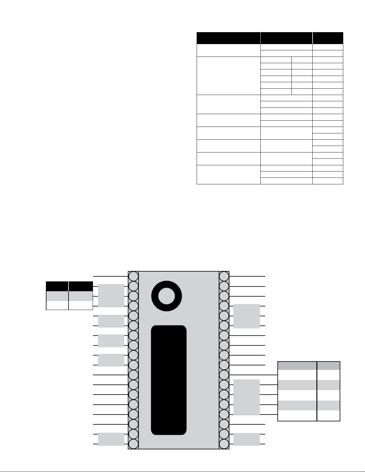
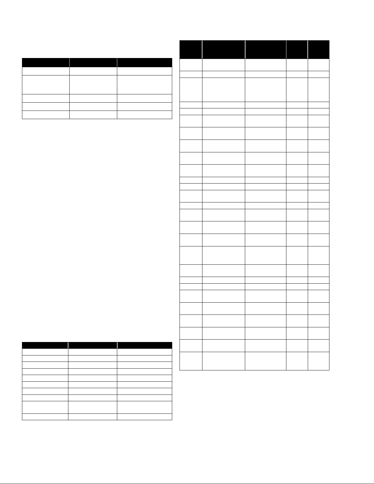
2. Kelvin II Connections
The Kelvin II has screw terminals on the each side of the
controller. The controller should be wired as follows and as
shown in Figure 1.
Figure 1
Item Wire (line)
Power
Valve
RS-485
Liquid Line Solenoid
Auxiliary Temperature Sensor
(Displayed menu item: S-3)
Room Temperature Sensor
(Displayed menu item: CtP)
Coil Out Temperature Sensor
(Display option: tout)
Pressure Transducer
(Displayed menu item: SucP)
24VAC 1
24 VAC 2
SEI, SER, SEH ESX —
N/C Gray 4
Black Orange 5
White Yellow 6
Green Red 7
Red Black 8
Ground 13
A+ 14
B- 15
Line 19
Load 20
T3
T2
T1
Sense (WHITE) 33
Ground (GREEN) 34
+5 VDC (BLACK) 35
Kelvin II
connect point
27
28
29
30
31
32
3. Kelvin II Display
Upon the rst power-up from Sporlan, the Kelvin II will enter the setup menu. This menu allows the user to set some
critical setpoint values, seen in Table 1, before the controller
will operate. These critical values can be set via the local or
remote displays, MODBUS, or Network Master. (Note: Only
the Valve Type and Refrigerant have to be set via MODBUS
or Network Master for the controller to operate) Once these
values are entered the Kelvin II will then begin its control. If
the setup menu is displayed on the local or remote displays
Page 3
Page 2
and the user sets these values via MODBUS then the Kelvin
II will automatically leave the setup menu.
Table 1 Setup Menu
Displayed Menu Item Description Selections
StEP
rEFr
PtYP
un_T
un_P
Valve Type 1596, 3192, 2500, 6384, 400
Refrigerant
Pressure Sensor Type gAUg, AbSL
Temperature Units FAHR, CELS
Pressure Units PSI, BAR
r22, 134A, 402A, 404A,
407A, 407C, 410A, 417A,
r507, 422d, r744, 245F
After setup, the Kelvin II defaults to showing the Superheat
value. The user can then turn the knob to view the other process values of their system. The screen will alternate between
the process values identity and value alternating every 3 seconds. For ease of use, the value that is displayed for a process
value may come in the form of text to eliminate the need of
‘looking up the meaning’. The menu text and meanings for
process values are described in Table 2.
The user may also view/edit the setpoints by pressing the knob
and holding it down for 5 seconds. The user is then prompted
for a password to verify his credentials. The knob should be
rotated up to ‘111’ for the password. If the password is correct the user may change the setpoints to the value he desires
in order to obtain optimum system performance. The menu
text and meanings for setpoint values are described in Table 3.
Setpoints are saved to the controller when the user leaves the
Setpoint menu by pressing the knob when “ESC” is shown.
The setpoint menu has a timeout of 60 seconds for inactivity. When this timeout is reached the controller goes back to
showing the process values and does not save any setpoints
that might have been changed. If the user is in the Manual
Valve Position setpoint then this timeout length is 60 minutes.
As long as the controller does not time out the 60 minutes,
Setpoints are saved to the controller when the user leaves the
Setpoint menu by pressing the knob when “ESC” is shown.
All process values and setpoints are accessible1 through the
local and remote displays.
Table 2 Process Value Menus
Displayed Menu Item Description Range
SuPH
SucP
tSAt
tout
CtP
PoSn
S-3
rELA
StAt
ALS
Superheat 0 to 165°F, 0 to 91.6°C
Suction Pressure
Saturation Temperature -60 to 150°F, -51.1 to 65.6°C
Suction Temperature -60 to 150°F, -51.1 to 65.6°C
System Temperature -60 to 150°F, -51.1 to 65.6°C
Valve Position 0 to 100% Open
Auxiliary Temperature
Solenoid Status dEng, Eng
System Cycle Status
Alarm Status
4
0 to 150 PSI, 0 to 10.34 Bar
2
-60 to 150°F, -51.1 to 65.6°C
Current cycle and manual
3
valve position state
noAL or all active alarms
Table 3 Setpoint Menu
Displayed
Menu
Item
ESC
SHSP
rEFr
d_On
dOFF
d_St
CtSP
H_oP
C_in
Cout
HiCP
SUPS
-P-
-I-
-d-
StEP
SPoS
nEt
Addr
un_P
un_T
PtYP
CaLP
CLt1
CLt2
CLt3
CAdr
Description Range
Escape and save
settings
Superheat Setpoint 0 to 45°F, 0 to 25°C 8
Refrigerant
Delay On 0 to 60 seconds 0
Delay Off 0 to 60 seconds 0
Delay Percent Open
of Valve
Cut-out Suction
Pressure
Maximum Operating
Pressure
Cut-in Temperature
Cut-out Temperature
Max Valve Capacity 20 to 100% 100
Supermarket Setting OFF, ON OFF
Proportional
Coefficient
Integral Coefficient 0 to 100 25
Derivative
Coefficient
Valve Type
Manual Valve
Position
Network Type
(MODBUS or
Network Master)
MODBUS/Network
Master Address
Pressure Units PSI, BAR PSI
Temperature Units FAHR, CELS FAHR
Pressure Sensor
Type
Pressure Sensor
calibration value
Tout calibration
value
Ctp calibration value
S-3 calibration value
Controller Display
Address
— —
r22, 134A, 402A,
404A, 407A, 407C,
410A, 417A, r507,
422d, r744, 245F
0 to 100 percent 0
4
PSI,
0 to 150
4
4
4
Bar
PSI,
Bar
0 to 10.3
0 to 150
0 to 10.3
-60 to 125°F,
-51.1 to 51.6°C
-60 to 124°F,
-51.1 to 51.1°C
0 to 100 40
0 to 100 5
1596, 3192, 2500,
6384, 400
0 to 100% Open
nbUS (MODBUS)
or ProP (Network
Master)
1 to 255 1
AbSL, gAUg gAUg
-5 to 5 PSI,
-0.34 to 0.34 Bar
-5 to 5°F, -2.7 to
2.7°C
-5 to 5°F, -2.7 to
2.7°C
-5 to 5°F, -2.7 to
2.7°C
0 to 99
Default
Setting
404A
0
150
-59
-60
1596
Present
Position
nbUS
0
0
0
0
0 or 1
for local
display
User
Setpoints
4. Kelvin II MODBUS
The Kelvin II can communicate with a MODBUS master.
The Kelvin II will transfer process values and setpoints via
MODBUS.
1 Setpoints can only be viewed and edited when the proper password is entered.
2 The Auxiliary Temperature sensor input has a special Pumpdown feature. If a “short” or switch closure is placed across these terminals, the valve will
shut for pumpdown. The full details of this feature are described in Section 5.
3 The Alarm Status process value is described in Section 6.
4 The maximum value varies based on which refrigerant is selected. (R-410A is 300 PSI, R-744 is 500 PSI and all others are 150 PSI).
Page 4

Page 3
The Kelvin II only supports the RTU transmission mode. The
serial settings are as follows:
n 9600 baud
n 8 data bits
n 1 stop bit
n Even parity
The Kelvin II supports the ‘Read Input Registers’, ‘Read
Holding Register’, ‘Write Single Register’, ‘Read Multiple
Coils’ and ‘Write Single Coil’ function codes. Any other request will result in an exception response. The Kelvin II will
allow a full and partial block read of the Input and Holding
registers and Coils.
4.1. Scaling
In order to preserve precision, scaling was implemented when
using Bar or Celsius for units. PSI and Fahrenheit units are
both in whole numbers and have no scaling. The tables of the
MODBUS memory map below reect this implementation.
The Celsius values that are transferred via MODBUS are 10X.
For example, if Celsius is chosen for the temperature units
then 45°C is transferred for the Superheat. The actual Superheat is 4.5°C. If the user desired to change a setpoint they
should keep this in mind when they enter a value.
The Bar values that are transferred via MODBUS are 100X.
For example, if Bar is chosen for the pressure units then 1034
Bar is transferred for the Maximum Operating Pressure. The
actual Maximum Operating Pressure is 10.34 Bar. If the user
desired to change a setpoint they should keep this in mind
when they enter a value.
4.2. MODBUS Memory Map
Table 4 Memory Map
MODBUS
Function
Code
Read Coils
(0x01)
Read Holding
Register
(0x03)
Mapped
Data
Manual
Valve
Control
Setpoints
Data Map Range
Bit 0 = Manual Valve
Enabled Flag
Bit 1 = Manual Valve
Duration Enabled
Flag
0. Superheat
Setpoint
1. Refrigerant Type
2. Delay On Relay 0 to 60 seconds
3. Delay Off Relay 0 to 60 seconds
4. Delay Steps 0 to 100 % Open
5. Cut-out Suction
Pressure
0 = Disabled,
1 = Enabled.
0 to 45°F, 0 to 250°C
(0.0 to 25.0°C)
0 = r22 1 = 134A
2 = 402A 3 = 404A
4 = 407A 5 = 407C
6 = 410A 7 = 417A
8 = 422A 9 = 422d
10 = r507 11 = r744
12= 245F
5
PSI, 0 to 1034
0 to 150
Bar (0 to 10.34 Bar)
MODBUS
Function
Code
Read Holding
Register
(0x03)
Read Input
Registers
(0x04)
Mapped
Data
Setpoints
Process
Variables
Data Map Range
6. Max Operation
Pressure
7. Temperature
Cut-in
8. Temperature
Cut-out
9. Valve Maximum 20 to 100 %
10. Supermarket
Mode
11. P 0 to 100
12. I 0 to 100
13. D 0 to 100
14. Valve Type
15. Manual Valve
Position
16. Network Type
17. Unit Address 1 to 255
18. Pressure Units 0 = PSI, 1 = BAR
19. Temperature
Units
20. Pressure Sensor
Type
21. Pressure
Calibration Offset
22. Suction
Temperature
Calibration Offset
23. Room
Temperature
Calibration Offset
24. Auxiliary
Temperature
Calibration Offset
0. Superheat
1. Suction
Pressure
2. Saturation
Temperature
3. Suction
Temperature
4. Room
Temperature
5. Valve Capacity
6. Auxiliary
Temperature
7. Relay Status
6
6
0 to 150
Bar (0 to 10.34 Bar)
-60 to 125°F,
-511 to 516 °C
(-51.1 to 51.6 °C)
-60 to 124°F,
-511 to 511 °C
(-51.1 to 51.1 °C)
0 = OFF 1 = ON
0 = 1596 1 = 3192
2 = 2500 3 = 6384
4 = 400
0 to 100 % Open
0 = MODBUS
1 = Network Master
0 = FAHR, 1 = CELS
0 = GauG, 1 = ABSL
-5 to 5°F,
-34 to 34 Bar
(-0.34 to 0.34 Bar)
-5 to 5°F,
-27 to 27°C
(-2.7 to 2.7°C)
-5 to 5°F,
-27 to 27°C
(-2.7 to 2.7°C)
-5 to 5°F,
-27 to 27°C
(-2.7 to 2.7°C)
0 to 165°F,
0 to 916°C
(0 to 91.6°C)
0 to 150 PSI,
0 to 1034 Bar
(0 to 10.34 Bar)
-60 to 150°F,
-511 to 656°C
(-51.1 to 65.6°C)
-60 to 125°F,
-511 to 656°C
(-51.1 to 65.6°C)
-60 to 125°F,
-511 to 656°C
(-51.1 to 65.6°C)
0.0 to 100.0% Open
(0.0 to 100.0)
-60 to 125°F,
-511 to 656°C
(-51.1 to 65.6°C)
0 = Deenergized,
1 = Energized
PSI, 0 to 1034
5 The maximum value varies based on which refrigerant is selected. (410A is 300 PSI, r744 is 500 PSI and all others are 150 PSI).
6 The maximum value varies based on which refrigerant is selected. (410A is 300 PSI, r744 is 500 PSI and all others are 150 PSI).
Page 5

Page 4
MODBUS
Function
Code
Read Input
Registers
(0x04)
Write Single
Coil (0x05)
Write Single
Register
(0x06)
Mapped
Data
Process
Variables
Manual
Valve
Control
Setpoints Same as above.
Data Map Range
8. Alarm Status
9. System Cycle
Status
Bit 0 = Manual Valve
Enabled Flag
If Bit set then alarm is
active:
Bit 0 = Suction
Transducer Failure
Bit 1 = Tout Sensor
Failure
Bit 2 = High Superheat
Bit 3 = Low Superheat
If Bit set then mode is
active:
Bit 1 = Setup Mode
Bit 2 = Off Cycle
Bit 3 = Cooling Cycle
Bit 4 = Pump-down Cycle
Bit 5 = Manual Valve
Override Mode
0 = Disabled,
1 = Enabled.
The Manual Valve
duration Bit is read-only.
The max number of
registers written at a
time is
1. The limits can be
seen above in the
‘Read Holding
Register’ definition.
5. Kelvin II Features
5.1. Pumpdown Feature
The Kelvin II will initiate a pumpdown when Auxiliary Temperature sensor terminals are shorted. If desired, this temperature connection could be set up as a dry contact. When a
pumpdown is desired the contact should be closed. The pumpdown will be ended when the short is removed provided that
there are no sensor alarms.
Normally, on the process value screens, the process value
text alternates with its value. When an alarm is activated the
alarm status “-AL-“screen is added to the rotation to make the
user aware that an alarm has been activated. The Alarm Status
menu display item ALS, will show the active alarms shown
in Table 5.
7. Kelvin II Display Networking
The Kelvin II displays can be set up to access other Kelvin II
controllers on the network. The controller’s current ‘CAdr’
value can be determined by pressing down the button on the
display while viewing a process value. To enable the display
network the ‘CAdr’ setting MUST be set to a unique nonzero
value with the RJ-45 connector on the side of the controller
DISCONNECTED.
After ‘CAdr’ has been set, an ‘End’ screen is added just before the ‘SuPH’ process value. Pressing the button on the
display while viewing the ‘End’ screen brings up a menu allowing the selection of other Kelvin II controllers connected
to the display network. Turning the knob allows the selection of other Kelvin II controllers based on their appropriate
‘CAdr’ address. The local controller is listed as ‘LocL’ by a
local display. Note: the remote display always includes the
‘End’ screen since it must be able to view any controller on the
display network.
8. Kelvin II Factory Reset
A factory reset can be performed by holding the button down
on the local or remote displays for 5 seconds when power is
rst applied. If using a local display the display will show
‘FrSt’ while the factory reset is being performed and then
automatically connect to the local controller.
5.2. Manual Valve Position Feature
The Kelvin II has the ability to manually control the valve.
To enable this manual control via the local or remote displays
simply open the setpoint menu and edit the ‘SPoS’ setpoint.
When the value is displayed for this setpoint the user is manually controlling the valve. The valve position can be changed
by rotating the knob clockwise or counterclockwise. There is
an inactivity timer of 60 minutes while in manual control. The
timer is reset each time the user moves the valve. The manual
control of the valve is ended when the user presses the knob to
go back to displaying ‘SPoS’ or a timeout has been reached.
6. Kelvin II Alarms
The Kelvin II has 4 alarms. The following table lists the
possible alarms and the text that is seen on the controller.
The controller’s alarm status can be viewed via MODBUS,
Network Master, and local and remote displays.
Table 5 Alarms
Alarm Text Meaning
NoAL
PSAL
TSAL
HSAL
LSAL
No Alarms active
Pressure Sensor alarm
Tout Sensor alarm
High Superheat alarm
Low Superheat alarm
If using a remote display the display will show ‘FrSt’ and
switch to a menu that allows the selection of the controller
to reset. To perform a factory reset, select the controller with
the appropriate ‘CAdr’ value. The display should show ‘----‘
while the reset is being performed. When nished performing factory resets turn the knob counterclockwise until ‘ESC’
is shown on the display. Pressing the button while ‘ESC’ is
shown on the display exits the factory reset menu and should
automatically connect to a controller on the display network.
Table 6 Replacement Parts
Part Number Description
952560 Kelvin II without display
952561 Kelvin II with local display
952562 Kelvin II Remote panel display
952662 Temperature Sensor Assembly
952795 Well Sensor Kit
953091 Pressure Transducer 150 psig with cable
952995 Pressure Transducer 150 psia with cable
952740
952504
Pressure Transducer 300 psig with cable for
R-410A applications only
Pressure Transducer 500 psig with cable for
R-477 applications only
Page 6

Parker Hannifin Corporation
Sporlan Division
206 Lange Drive • Washington, MO 63090 USA
phone 636 239 1111 • fax 636 239 9130
www.sporlan.com
112009 / SD-324
 Loading...