

Page 1
INSTALLATION & SERVICE MANUAL
Quik Load doors and frames
May 2008
Page 2

Table of contents
3-5. Warranty
6. Serial plates
7. Frame inst allation
8. Door Installation
9. Door removal
10. Reversing the door swing
11. Replacing the door heater
12. Removing and replacing the torque rod
13. Gasket and handle replacement
14. Replacing a frame heater
15. Anti-sweat heater information
16. Blank
17. Replacing light fixtures
18-19. Ballast/power su pply replacement and lighting schematics
20. Exploded View – Door
21. Exploded Vie w – Fr ame T8
22. Exploded Vie w – Fr ame Gelcore
23. Exploded View – Frame Crossfire
24. Care and cleaning information
Page 3

6/25/08 - Rev. A Page 3
SCHOTT Gemtron Food Display
WARRANTIES AND GENERAL TERMS AND CONDITIONS
CONDITIONAL ACCEPTANCE OF ORDER: SCHOTT Gemtron Corporation’s (“SCHOTT
Gemtron”) acceptance of customer’s order and therefore, the formation of a valid contract for
sale, is EXPRESSLY CONDITIONED on Customer’s acceptance of the general terms and
conditions as set forth herein and any additional terms and conditions indicated on the face of
SCHOTT Gemtron’s Conditional Acceptance of Order or quotation. Customer will be deemed to
have accepted these general terms and conditions and any general terms an d conditions
indicated on the face of SCHOTT Gemtron’s Conditional Acceptance of Order or quotation unless
customer shall object thereto in writing within five days from receipt of SCHOTT Gemtron’s
Conditional Acceptance of Order or quotation or upon acceptance of all or any parts of the goods
ordered, whichever occurs first.
ADDITIONAL TERMS AND CONDITIONS: The terms and conditions as set forth on SCHOTT
Gemtron’s Conditional Acceptance of Order, quotation, or price lists shall be considered
additional terms and conditions of this sale. SCHOTT Gemtron and the purchaser acknowledge
that all of the terms and conditions applicable to this sale reflect an acceptable allocation of the
rights and obligations of the parties to this sale.
SHIPMENT OF GOODS / RETURN OF GOODS: Every effort will be made to ship the goods on
the scheduled shipment date and to maintain production schedules consistent therewith.
SCHOTT Gemtron will not be liable, however, for any claims arising from the failure to meet any
scheduled shipping dates. If Buyer refuses shipment of any standard catalog products under an
acknowledged order and those products are consistent with that order and are not delivered
damaged or defective, then Buyer will be responsible for:
1. Return shipment of the products to SCHOTT Gemtron in original shipping containers;
2. Return freight to SCHOTT Gemtron prepaid by Buyer; and
3. A restocking charge to be determined by SCHOTT Gemtron of not less than twenty-five
percent (25%) of the sales price. Buyer assumes the risk of any return shipment damage or loss,
the cost of which will be assessed by SCHOTT Gemtron and added to the restocking charge. No
custom products or custom sizes of catalog items may be returned to SCHOTT Gemtron fo r
credit unless those products are not consistent with an acknowledged order or they are defective.
If they are defective, SCHOTT Gemtron reserves the right to correct the defect at the ship-to
location.
TERMS OF CREDIT: All credit terms are net 30 days from date of invoice. Any deductions from
the net invoice amount must be approved by an authorized representative of SCHOTT Gemtron.
If credit is extended to Buyer, SCHOTT Gemtron reserves the right to revoke such credit if Buyer
fails to make timely payment for any goods delivered. SCHOTT Gemtron reserves the right to
require payment or other assurances which it deems necessary prior to the shipment of any
goods, if, in SCHOTT Gemtron's opinion, exercised in SCHOTT Gemtron's subjective, good faith
judgment, the Buyer's financial condition has deteriorated or the risk of non-payment has
otherwise increased. Credit is subject to approval upon receipt of completed credit application.
Any goods shipped prior to credit approval shall be shipped "Cashiers Check", or pre-payment. A
$50.00 charge will be applied for each returned check. Goods may not be returned for credit
unless prior authorization and an authorization number have been granted by SCHOTT G emtron.
A 1-1/2% per month charge will be assessed on past due amounts.
SCHOTT Gemtron Food Display • 2840 Nebo Road, Madisonville, KY 42431
Toll Free: 800.326.2717 • Phone: 270.821.2864 • Fax: 270.326.3624
FWTC1011
Page 1 of 4
Page 4

6/25/08 - Rev. A Page 4
LIMIT ON REMEDIES IN EVENT OF FAILURE: In the event any SCHOTT Gemtron product fails
to perform as warranted, SCHOTT Gemtron’s sole responsibility and PURCHASER’S SOLE AND
EXCLUSIVE REMEDY under any warranty, contract, negligence or other claim of liability shall be
limited to a refund of SCHOTT Gemtron’s original selling price or, at SCHOTT Gemtron’s option,
furnishing the purchaser with another product without charge F.O.B. Madisonville, Kentucky. In
no event shall SCHOTT Gemtron be liable for cost incurred in the removal of failed products, the
installation of replacement products, OR ANY INCIDENTAL OR CONSEQUENTIAL DAMAGES
INCURRED AS NON-PERSONAL INJURY LOSSES. In the event a product is replaced pursuant
to any applicable SCHOTT Gemtron warranty, the replacement product is warranted only for the
remainder of the warranty period applicable to the original product. SCHOTT Gemtron shall not
be liable for any allegedly defective product unless SCHOTT Gemtron first has the right to inspect
such product and verify the defective condition.
CLAIMS BY BUYER: All claims by Buyer against SCHOTT Gemtron, including claims for alleged
shortages, must be made in writing and delivered to SCHOTT Gemtron within 30 days of receipt
of the goods. SCHOTT Gemtron shall thereupon be afforded a reasonable opportunity to inspect
the goods. All claims not made in the time period and manner specified above shall be deemed
waived. All actions, claims or defenses by Buyer shall be deemed waived unless commenced or
asserted within 6 months of receipt of the goods.
WARRANTY: The following shall be the sole and exclusive warranty for products sold by
SCHOTT Gemtron Food Display with the exception of the SCHOTT Gemtron Food Display
Limited Warranty (Form No. W1010): SCHOTT Gemtron warrants to Customer that all Products
will conform to and perform in accordance with the applicable current specifications issued by
SCHOTT Gemtron. This warranty shall not apply to any Product that shall have been subject to
misuse, abuse, accident, disaster, or which has been used co ntrary to current instructions.
THE FOREGOING WARRANTIES ARE THE SOLE WARRANTIES, EXPRESS OR IMPLIED,
GIVEN BY SCHOTT GEMTRON IN CONNECTION WITH THE PRODUCTS, AND SCHOTT
GEMTRON DISCLAIMS ALL OTHER WARRANTIES, INCLUDING WARRANTIES OF
MERCHANTABILITY, FITNESS FOR A PARTICULAR PURPOSE AND NON-INFRINGEMENT
OF THIRD PARTY RIGHTS.
SCHOTT Gemtron assumes no liability for consequential damages, anticipated or lost profits,
incidental damages, loss of time, or other losses incurred by Customer or any third party in
connection with the Products.
SUITABILITY OF PRODUCTS: Purchaser shall be solely responsible for determining the
suitability for use of the products purchased from SCHOTT Gemtron. Representations by
employees or agents of SCHOTT Gemtron (other than the warranties specified herein)
concerning the suitability of SCHOTT Gemtron’s products are not authorized by SCHOTT
Gemtron and may not be relied upon by the purchaser.
PERMISSIBLE VARIATIONS, STANDARDS AND TOLERANCES: Except in the particulars
specified by purchaser and expressly agreed to in writing by SCHOTT Gemtron, all material shall
be produced in accordance with SCHOTT Gemtron’s standard practices. All material, including
that produced to meet an exact specification, shall be subject to tolerances and variations
consistent with usages of the trade and regular factory practices concerning dimensi on, weight,
straightness, section, composition and mechanical properties, normal variations in surface,
internal conditions and quality, and deviations from tolerances and variations consistent with
practical testing and inspection methods.
SCHOTT Gemtron Food Display • 2840 Nebo Road, Madisonville, KY 42431
Toll Free: 800.326.2717 • Phone: 270.821.2864 • Fax: 270.326.3624
FWTC1011
Page 2 of 4
Page 5

6/25/08 - Rev. A Page 5
CHANGES IN ORDER: SCHOTT Gemtron reserves the right to void any quotation for price or
terms in the event the customer to whom such quotation is made changes his order with respect
to any factor reflected in price or other terms originally ordered or quoted.
CHANGES BY SCHOTT GEMTRON: SCHOTT Gemtron reserves the right to change design,
colors and specifications of any goods without notice to Buyer.
DEFAULT: If Buyer defaults on the purchase of any goods or if a petition in bankruptcy is filed by
or against Buyer, SCHOTT Gemtron, in addition to other remedies, may repossess any goods
which were previously delivered and for which payment has not been received and may refuse to
make further shipment of goods. Buyer agrees to pay SCHOTT Gemtron's costs and expenses of
collection or repossession including the maximum attorney's fee permitted by law.
WE ASSUME NO RESPONSIBILITY FOR BREAKAGE IN TRANSIT: Breakage on arrival
should be noted on Bill of Lading and a claim filed PROMPTLY with carrier.
PREVAILING PRICE: Unless specifically indicated otherwise in writing, all orders are deemed to
be at the price prevailing at the date of shipment.
FINAL ACCEPTANCE OF ORDERS: All orders are subject to final acceptance at SCHOTT
Gemtron’s office in Madisonville, Kentucky. Conditional acceptance is evidenced by SCHOTT
Gemtron’s Conditional Acceptance of Order or shipment of the ordered products and final
acceptance is effective according to the provisions herein.
CHANGE OF TERMS: Prices, terms and conditions of sale are subject to change without notice.
PRICE QUOTATIONS: All prices are quoted in U.S. dollars.
PAYMENT OF TAXES: Any federal, state or municipal tax imposed by virtue of the sale
hereunder shall be added to the invoice and paid by the purchaser without discount.
FORCE MAJEURE. Except for the payment of money, neither party shall be held responsible for
any delay or failure in performance of any part of this Agreement to the extent that delay or failure
is caused by causes beyond its control (“Force Majeure Conditions”), including, but not limited to,
fire, flood, explosion, war, strike, embargo, government requirement, civil or military authority, act
of God, act or omission of carriers or other similar causes. If any Force Majeure Condition occurs,
the party delayed or unable to perform (“Delayed Party”) shall give immediate notice to the other
party (“Affected Party”), and the Affected Party, upon giving prompt notice to the Delayed Party,
shall be excused from performance under this Agreement for the duration of the Force Majeure
Condition, provided, however, that the Affected Party shall take all reasonable steps and
cooperate with the Delayed Party to avoid or remove the cause of non-performance and shall
resume performance hereunder with dispatch when the cause is removed; and provided further
that if the Delayed Party cannot within sixty (60) days remove the cause of non-performance, the
Affected Party may terminate this Agreement.
NON-WAIVER:Waiver by SCHOTT Gemtron of a breach of any of the terms and conditions of
this sale shall not be construed as a waiver of any other breach. The mere passage of time shall
not constitute a waiver under the terms and provisions of this sale.
WAREHOUSING: Prices in our price lists are for quantities ordered for production and shipment
at one time. The warehousing charge of 1-1/2% per month will be applied to invoices covering
material which has not been picked up or released for shipment within thirty days after notification
that the order is ready.
SCHOTT Gemtron Food Display • 2840 Nebo Road, Madisonville, KY 42431
Toll Free: 800.326.2717 • Phone: 270.821.2864 • Fax: 270.326.3624
FWTC1011
Page 3 of 4
Page 6

6/25/08 - Rev. A Page 6
CANCELLATIONS: Cancellation of any acknowledged order from SCHOTT Gemtron must be
approved in writing by SCHOTT Gemtron Food Display in Madisonville, Kentucky. SCHOTT
Gemtron shall be entitled to receive, upon demand, liquidated damages of not less than 10
percent (10%) of the purchase price of the order, plus the cost of all materials and work furnished
or done upon time of the cancellation by the purchaser.
SEVERABILITY: If any provision of the terms and conditions specified herein shall be deemed
invalid or unenforceable, the remaining terms and conditions shall be construed as though such
provision does not appear herein and shall be otherwise fully enforceable.
MODIFICATION: No distributor, representative, agent or employee has the authority to alter or
change any product warranty, either orally or in writing.
SCHOTT Gemtron Food Display • 2840 Nebo Road, Madisonville, KY 42431
Toll Free: 800.326.2717 • Phone: 270.821.2864 • Fax: 270.326.3624
Email: info@gemtronfooddisplay.com
FWTC1011
Page 4 of 4
• www.gemtronfooddisplay.com
Page 7
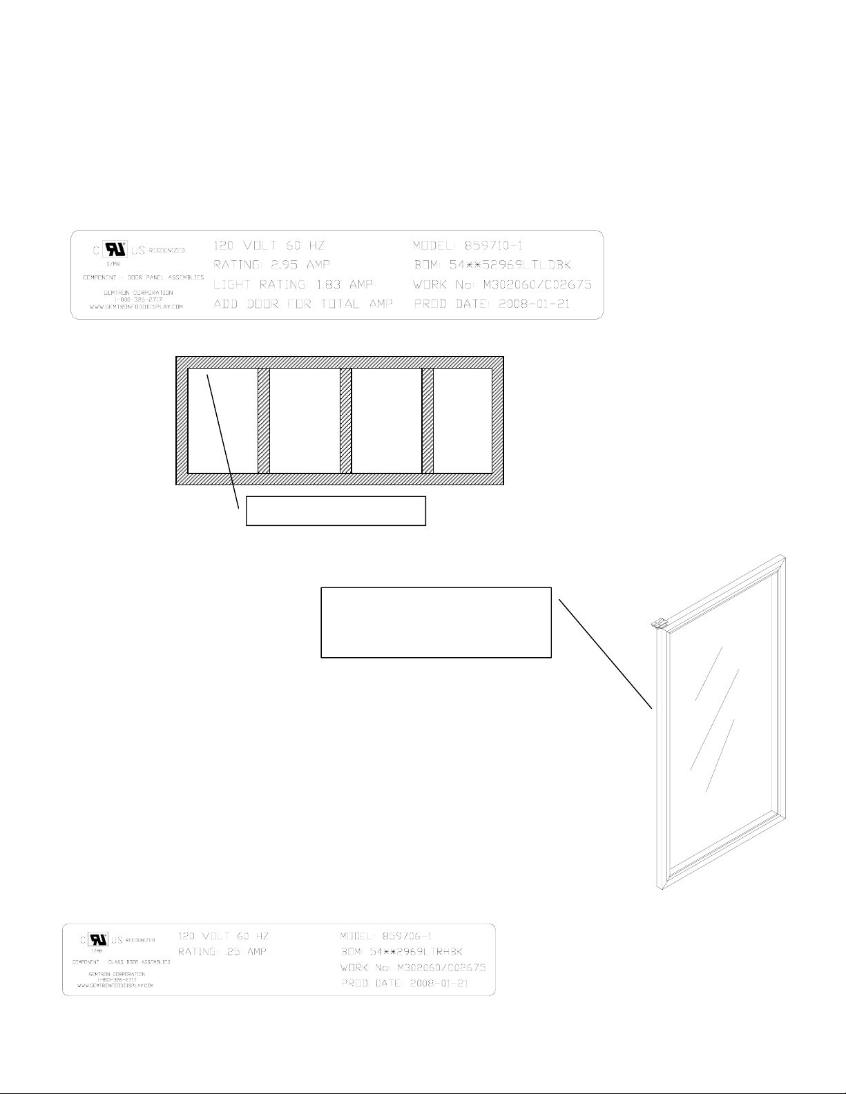
Serial plate
To assist our customer with technical information or ordering spare parts, frames and doors
have a serial plate which informs about Type number, manufacture date, order number and
electric ratings.
Frame Serial Plate
Door Serial Plate
Frame Seri al Plate
Door serial plate is located on
the top or on the hinge side of
door
Page 8
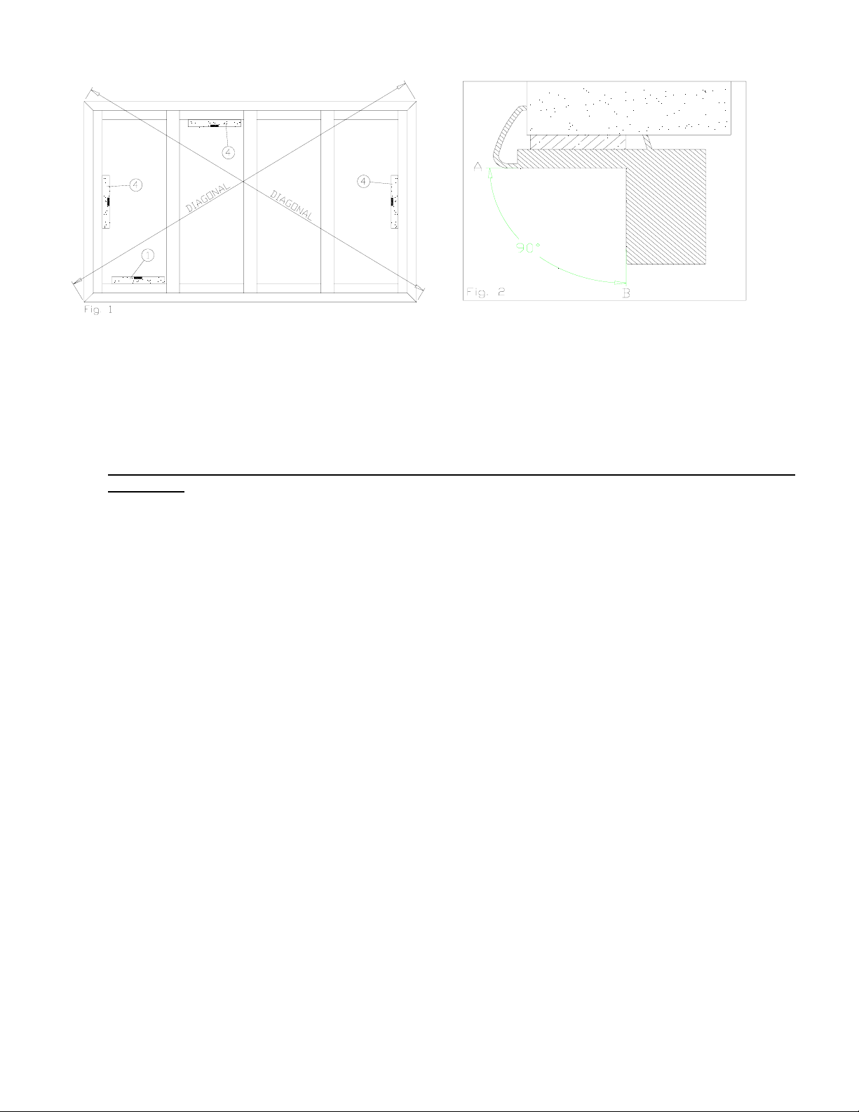
Frame Installation
6/25/08 - Rev. A Page 8
1. Place frame into opening in the panel. Clamp top of frame. Check horizontal alignment with a level (1), then
fasten bottom of frame with mounting screws.
2. Use spacer at the upper horizontal to prevent distortion of frame (Fig 2).
Attention! Make sure that the gap is filled, to keep the profile from bending out. Surface “A” and “B” must be
keep at 90◦.
3. Make sure both diagonals are equally long.
4. Check vertical and horizontal sides with a level (4). Fasten the side profiles and the upper vertical with
mounting screws. Any gaps between the frame and cooler/freezer wall needs to be insulated with sealant to
prevent air leaks.
Page 9

Installing a Door
1. Handling each door carefully, install them into the frame, one at a time by inserting the torque rod-end
into the cavity of the torque adjuster.
2. Tilt the top of the door up and toward the frame, inserting the hinge pin into the Gib, located in the top of
the door frame making sure that the spring clip engages into the upper frame rail.
3. Insert the hold-open bolt through the elongated hold-open slot and into the frame mounting hole. Tighten
with a Phillips-head screwdriver.
4. Adjust the door swing and door squareness by adjusting the torque adjuster. (see Torque and Sag
Adjustment)
NOTE: Do not use power tools to adjust the torque adjuster.
NOTE: Do not over-tighten the hold-open bolt (torque to 45-51 inch pounds). Be certain that the hold-open does
not bind while sliding along the hold-open bolt and adjust as necessary.
1. 2. 3.
Torque and Sag Adjustment
The torque adjuster regulates the door squareness and tension of the door swing.
1. Use the flathead screwdriver, adjust the torque rod tension
by turning the outside screw on the torque adjuster.
• Turn counter-clockwise to increase tension.
• Turn clock-wise to decrease the tension.
2. Adjust the door sag to square it in the frame by turning the screw
that is marked SAG ADJ. (sag adjustment), on the end of the
torque adjuster, until the door slowly closes itself.
• Turn the screw clockwise to lower the handle side of the door.
• Turn the screw counter-clockwise to raise the door’s handle side.
NOTE: Do not use power tools when adjusting the torque adjuster. To check for proper door closing tension, open
the door approximately 1 inch and release the door. The door should self close without any assistance.
Page 10

Removing a Door
6/25/08 - Rev. A Page 10
1. Using a flat-head screwdriver, turn the
adjustment screw on the front of the torque
adjuster clockwise until the door no longer
self-closes.
2. Open the door to access the hold-open
device and remove the mounting bolt from
the frame using a Phillips-head
screwdriver.
3. With the door in a nearly closed position,
insert the top half of the needle-nose pliers
into the grip hole in the hinge pin spring
clip and the bottom half of the pliers
beneath the hinge pin shroud.
4. Squeeze the pliers to pull down the spring
clip, while simultaneously pulling the top
of the door away from the frame and pull
the top of the door out.
5. Lift and remove the door from the torque
adjuster.
NOTE: Exercise caution when handling the door.
Page 11

Reversing the Door Swing
6/25/08 - Rev. A Page 11
1. Using a flat-head screwdriver, loosen the torque adjuster from its mount by turning the center mounting
screw counter-clockwise less than one-half (1/2) of a turn.
2. Remove the torque adjuster, exposing the mounting hole in the bottom frame rail.
3. Locate the mounting hole at the opposite side of the door opening.
4. Using the flat-head screwdriver, carefully pry underneath the plug cap and remove it.
5. Place the torque adjuster on the newly opened mounting hole, aligning the flanged corners of the mounting
tabs.
6. Insert the torque adjuster mounting tabs onto the mounting hole with the hollow end of the torque adjuster
against the door frame.
7. Confirm that the mounting flanges on the bottom of the torque adjuster align with the corner mounting slots
of the mounting hole in the frame.
8. Using a flat-head screwdriver, turn the torque adjuster mounting set-screw clockwise, for 1/2 a turn, to
tighten the mount and lock it in place. Confirm that the torque adjuster mounting is flush with the door
frame.
9. Using a Phillips head screwdriver, loosen and remove the hold-open bolt from the top frame rail.
10. Relocate and install the hold-open shoulder bolts into the opposite hold-open mount of the same door
frame.
11. Open the vertical side access to the hinge pin wire connections in the rail on the hinge side of the door
assembly.
12. Disconnect the Hot, Neutral and Ground wires of the hinge pin from the heater wire circuit and the ground
terminal.
13. Completely remove the hinge pin assembly from the top door rail.
14. Using a plastic mallet and a flat-head screwdriver, remove the torque rod from the bottom of the door
assembly.
15. Swap placement of the Hinge Pin and Torque Rod to the other’s original mounting hole in the door
assembly hinge side rail.
16. Reinstall the hinge pin and the torque rod completely into the ends of the door assembly hinge rail.
17. If necessary, lightly tap on the hinge pin and torque rod with a plastic or rubber mallet until each is fully
seated into the top and bottom of the door.
18. Reconnect the hinge in wires and confirm that all connections are secure.
19. Check and confirm torque rod and hinge pin are correctly and completely installed.
20. Reinstall the door into the frame.
1. 8. 12.
13. 14. 17.
Page 12

6/25/08 - Rev. A Page 12
Door heater replacement
1. Disconnect frame from power source. Remove the
door. Remove the magnetic gasket (A) by starting
on the upper corner and work your way down.
Carefully remove plastic (B) cover with a
screwdriver, starting at the upper corner (Fig. 1). If
plastic cover becomes damaged it has to be
replaced.
2. Refer to Fig. 2 for heater wire location. Remove the
heater from the door rail, and cut the leads at the
hinge pin power connection.
3. Starting at the upper hinge side corner, run the new
heater around the door, pressing the heater into the
aluminum channel the old one was removed from.
4. Connect the new heater to the hinge pin leads as
shown in Fig. 3.
5. Carefully replace the plastic back molding.
Reinstall the gasket (see gasket replacement
instructions). Reinstall the door (see door
installation instructions).
Page 13

Removing and Replacing the Torque Rod
6/25/08 - Rev. A Page 13
1. Carefully place a flathead screwdriver between the door rail and the washer beneath the torque rod. (A)
2. Dislodge the torque rod from the door by pushing on the torque rod or tap it loose using a plastic or rubber
Mallet. (B)
3. Once dislodged pull the torque rod completely out of the door.
4. Reinstall a new torque rod by inserting it into the same hole fully seating it with a plastic or rubber mallet. (C)
A
B C
Page 14

Gasket replacement
6/25/08 - Rev. A Page 14
1. Remove the magnetic gasket (A) by starting on the upper corner and work your way down (Fig. 1).
2. To install a gasket, insert the lip around the inner edge of the gasket into the groove in the plastic on the back of the door
(B), then press the dart on the back of the gasket into the plastic on the back of the door (C) (Fig. 2).
Handle replacement
1. Remove the gasket (A) as much as necessary to access
the cut-outs (B) in the plastic, this will allow access to
the handle mounting screws (C) (Fig. 1).
2. Reinstall gasket (see gasket replacement instructions).
Page 15

Replacing a frame heater
6/25/08 - Rev. A Page 15
1. Disconnect the frame from its power source. Remove the doors, following
the instructions in the “Door removal” section of this book. Refer to
section 7, “Anti-sweat heater wiring diagram” for information on electrical
connection locations and heater part numbers.
2. Remove the plastic profiles covering the defective heater by first removing
the horizontal pieces, then the vertical pieces. Use a screwdriver to
carefully release the profiles (Fig. 2). Caution:
during removal.
3. Cut the defective heater approximately 8 inches from its end, and remove
it from the frame (Fig. 3).
4. Press the new heater into place using your finger. Be careful not to
damage the insulation on the heater. Splice the heaters using line-to-line
connectors (Fig. 4). WARNING! Only an authorized technician should
perform heating cable replacement.
5. To replace the plastic profiles (covers), begin with the vertical covers then
move on to the horizontal ones. To replace the plastic profile s on the
mullions, begin by hooking the plastic cover on the right side of the
mullion (Fig. 5A). Replace the metal cover, ensuring that it fits properly
under the plastic cover (Fig. 5B). Then install the left plastic cover on to
the mullion, using a rubber mallet to get it into position (Fig. 5C). If
getting the cover into position is difficult, try hammering on both sides of
the mullion. Be careful not to damage the plastic.
6. To replace the vertical and horizontal covers, begin by installing the
plastic cover on to the metal cover (Fig. 6A). Install the metal cover on to
the frame (Fig. 6B). Use a rubber mallet to position the plastic cover on to
the frame (Fig. 6C). For the covers to lock to the frame properly, the metal
must be inserted into the plastic correctly (Fig. 7)
7. Reinstall the doors following the “Door installation” instructions, and
reconnect the frame to its power source.
Do not damage the plastic
Fig.2
Fig. 3
Fig. 4
Fig. 5
Fig. 6 Fig. 7
Page 16

Blank – Page 16
Page 17

Replacing Lighting
6/25/08 - Rev. A Page 17
T8 lighting
1. Disconnect the frame from its power source.
2. Press together lamp cover and twist outwards.
3. Twist light tube 90◦ clockwise or counter
clockwise and remove it.
4. Install new light tube and reinstall lamp cover.
Attention! It is important that the lamp cover fits
tightly against the frame. If air leaks in, light tube
efficiency decreases.
Gelcore LED lighting
1. Disconnect the frame from its power source.
2. Use your thumb to press down on one side of
the mounting clip.
3. Twist the LED fixture out of the mounting clip.
4. The new LED fixture will snap into the existing
mounting clip.
Crossfire LED lighting
1. Disconnect the frame from its power source.
2. Remove the mounting screws at the top and
bottom of the LED fixture.
3. The new LED fixture will mount using existing
screws and mounting holes.
Page 18

Replacing a T8 ballast or
6/25/08 - Rev. A Page 18
Gelcore LED power supply
1. Disconnect the frame from its power source.
2. Remove the ballast/power supply cover (A)
located on the side of the mullion. Then
remove the ballast/power supply (B).
3. If quick connect plugs (C) are present, use
them to disconnect the wiring and replace the
ballast/power supply. If the plugs are not
provided, the wires must be cut at a length you
can comfortably connect the new power
supply. (see LED and T8 wiring diagrams for
detailed information on ballast/power supply
wiring)
4. Reinstall the ballast/power supply (B) and
cover (A). Reconnect the frame to its power
source.
Note: The power supply for Crossfire LED lighting is
built into the LED light fixture.
Page 19

6/25/08 - Rev. A Page 19
Note: The power supply for Crossfire LED lighting is built into the LED light fixture.
Page 20

Exploded view – Quik Load Door
6/25/08 - Rev. A Page 20
1. Corner Block
2. Door Rail
3. Heater Wire
4. Insulated Glass Unit
5. Plastic Back Molding
6. Hinge Pin
7. Cable Bushing
8. Torque Rod Assembly
9. Access Cover
10. Handle
11. Hold Open
12. Spacer
13. Screw
14. Backer Plate
15. Shoulder Bolt
16. Gasket
Note: For specific part numbers,
provide serial plate information.
Page 21

Exploded view – T8 frame
6/25/08 - Rev. A Page 21
• 1 Top lamp bracket
• 2 Lamp socket
• 3 Tube guard end cap
• 4 Tube guard
• 5 Lens
• 6 9 pin electrical connector
• 7 Width vinyl
• 8 Width contact plate
• 9 Quik Load torque adjuster
• 10 Ballast cover plate
• 11 Cover Plate Screw
• 12 Mounting hole plug
• 13 Ballast
• 14 Mullion contact plate
• 15 Mullion side vinyl
• 16 Vertical vinyl
• 17 Vertical contact plate
• 18 Light switch
• 19 Receptacle (NTH & LT only)
• 20 Gib
• 21 Hole plug (torque adjuster)
• 22 Lamp
• 23 Bottom lamp bracket
• 24 Lens spring clip
• 25 Lamp bracket mounting screw
Note: For specific part numbers, provide
serial plate information.
Page 22

Exploded view – Gelcore LED frame
6/25/08 - Rev. A Page 22
• 1 End LED light fixture
• 2 Mullion LED light fixture
• 3 End LED light bracket
• 4 Mullion LED light bracket
• 5 Lamp bracket mounting screw
• 6 9 pin electrical connector
• 7 Width vinyl
• 8 Width contact plate
• 9 Quik Load torque adjuster
• 10 Power supply cover plate
• 11 Cover Plate Screw
• 12 Mounting hole plug
• 13 Power supply
• 14 Mullion contact plate
• 15 Mullion side vinyl
• 16 Vertical vinyl
• 17 Vertical contact plate
• 18 Light switch
• 19 Receptacle (NTH & LT only)
• 20 Gib
• 21 Hole plug (torque adjuster)
Note: For specific part numbers, provide
serial plate information.
Page 23

Exploded view – Crossfire LED
6/25/08 - Rev. A Page 23
• 1 Left LED light fixture
• 2 Mullion LED light fixture
• 3 Right LED light bracket
• 4 -
• 5 -
• 6 9 pin electrical connector
• 7 Width vinyl
• 8 Width contact plate
• 9 Quik Load torque adjuster
• 10 -
• 11 -
• 12 Mounting hole plug
• 13 -
• 14 Mullion contact plate
• 15 Mullion side vinyl
• 16 Vertical vinyl
• 17 Vertical contact plate
• 18 Light switch
• 19 Receptacle (NTH & LT only)
• 20 Gib
• 21 Hole plug (torque adjuster)
Note: For specific part numbers, provide
serial plate information.
Page 24

Care & Cleaning:
6/25/08 - Rev. A Page 24
Gemtron Doors and Frames
Cleaning—Inside
The interiors of doors and frames should be cleaned at least once a year. Unplug the doors and
frames before cleaning. If this is not practical, wring excess moisture out of sponge or cloth when
cleaning around switches, lights, and controls.
Use a warm water and baking soda solution—about a tablespoon (15 ml) of baking soda to a quart
(1 L) of water. This both cleans and neutralizes odors. Rinse thoroughly with water and wipe dry.
When cleaning other parts of the doors and frames—including gaskets and all plastic parts—use the
same solution. After cleaning door gaskets, apply a thin layer of petroleum jelly to the door gaskets at
the hinge side. This helps to keep the gaskets from sticking and bending out of shape. Do not use
cleansing powders or other abrasive cleaners.
Cleaning—Outside
The exteriors of doors and frames can be cleaned with a cloth dampened with a solution of mild
liquid dishwashing detergent and water. Dry with a soft cloth.
Use a household wax, such as Pledge brand or Jubilee brand, to coat the handles. Soil will then easily
wash off with dish detergent and water or a non-abrasive all-purpose cleaner. Glass can be cleaned
with off-the-shelf glass cleaner.
Do not use scouring pads, powdered cleansers, bleach, or cleaners containing bleach because these
products can scratch and weaken the finish.
Gemtron ANTI-FOG/ANTI-FROST
COATED GLASS RECOMMENDED CLEANING
Gemtron’s Anti-Fog/Anti-Frost coating can sometimes become contaminated which degrades the Anti-Fog
performance. The result can be splotchy areas of fog or frost. Even certain cleaners can leave a residue that
blocks the Anti-Fog performance. The solution is to clean the undesirable residue off of the coating. The
best products for cleaning the Anti-Fog coating are degreasers. The preferred degreasing cleaner is
“Greased Lightning”.
Recommended cleaning procedures for Gemtron Anti-Fog/Anti-Frost coating:
Don’ts
• Do not use sealants, gaskets, or other materials containing silicone that can contaminate the coating.
• Do not use tape, glue, stickers, attachments, or magic markers on the anti-fog coating.
• Do not use razor blades or any other mechanical device to remove foreign residue or objects directly
• Do not use abrasive cleaners or materials on the coated glass. Examples of these cleaners or materials
• Do not use cleaners or materials on the coated glass that hinder the anti-fog performance by leaving
Do’s
• Recommended cleaners include: Greased Lightning, Formula 409 Grease & Grime, Formula 409 Grease
• Recommended cleaning is with a soft dry or slightly damp towel, or with one of the degreasing cleaners
from the coated glass.
include Ajax, Brillo, Comet, Scotch Brite, Steel Wool, and Soft Scrub.
residue or damaging the surface. Examples of these cleaners include: Armor All, Tilex, Bleach, Windex
No-Drip, Windex Wipes, Pledge, or any product containing silicone oils or waxes.
& Surface, Fantastic, Mr. Clean, Windex Vinegar, Windex Original, Now, or Mean Green (degreasing
cleaners). Isopropyl alcohol and acetone are also good degreasing cleaners. If you have any question
about the use of a particular cleaner, please contact AFG.
listed above.
Gemtron Food D isplay • 2840 Nebo Road, Madisonville, KY 42431 • To ll-Free: 800.32 6.2717 • Phone:
270.821.2864 • Fax: 270.326.3624
E-mail: info@gemtrondoors.com • www.gemtrondoors
.com
 Loading...