

Page 1
SMCP26FL Series
SMCP26PC Series
elf-Contained
Coolers
ZERO ZONE
Zero Zone, Inc. • 110 N. Oakridge Dr. • North Prairie, WI 53153-9792
1-800-247-4496 • FAX: 1-414-392-6450 • www.zero-zone.com
C
CRMA
Certified
S
S
SMCP26 Series
INSTALLATION
and
OPERATING INSTRUCTIONS
for
06995M21000129
Page 2

TABLE OF CONTENTS
SUBJECT
GENERAL INFORMATION…......................................................................... 1
INTRODUCTION.......................................................................................................... 1
INSPECTION................................................................................................................ 1
LOCATION.................................................................................................................. 1
INSTALLATION.............................................................................................. 1
ELECTRICAL................................................................................................................ 1
START-UP.............................................................................................................……. 1
USER INFORMATION................................................................................................ 2
CLEANING………………...……………….................................................................. 2
SHELF LOCATION....................................................................................................... 2
LANE DIVIDERS – (SHELF ACCESSORIES)................................................................. 2
SHELF GLIDES – (SHELF ACCESSORIES)...........…..................................................... 2
PRE CUT SALAD RACK – (SHELF ACCESSORIES)..................................................... 2-3
FLORAL SHELVES – (SHELF ACCESSORIES).........……….......................................... 3
TEMPERATURE CONTROL.......................................................................................... 3
LOADING THE COOLER............................................................................................ 3
LIGHT SWITCH………….............................................................................................. 3
COIL DE-ICING...…….............................................................................................. 3
SERVICE..................................................................................................…..................... 3
EVAPORATOR.................................................................................................................. 3-4
EXPANSION VALVE......................................................................................................... 4
EVAPORATOR FANS….………………...…................................................................ 4
LIGHTS………………................................................................................................... 4
ALTERNATE LIGHTING – T-8....................................................................................... 4
COMPRESSOR ACCESS PANEL (GRILL)................................................................... 4
COMPRESSOR…………………………...................................................................... 4
LIGHT BALLAST……………......................................................................................... 5
SIGNAGE…………………….…..……….................................................................... 5
CIRCUIT PROTECTION…………..……………..…….................................................. 5
PREVENTATIVE MAINTENANCE..........................................................….................. 5
SPECIFICATION SHEET………..........................................................…..................... 6
WIRING DIAGRAMS..………............................................................…..................... 7-8
WARRANTY……….…..………..........................................................…..................... 9
SMCP26
Page 3
GENERAL INFORMATION
Introduction
rays of the sun or near a source of radiant heat.
Locate on a floor with sufficient strength because if the
building floor sags, the cooler doors could bind. The
cooler must be level and plumb for proper operation.
The information contained in this manual pertains to
Zero Zone 2- and 3-door self-contained coolers used
for refrigerated food, pre-cut salads, or floral merchandising. Zero Zone has made every effort to
produce refrigeration equipment of the highest quality
using state of the art components and modern manufacturing techniques. Read these instructions carefully
and completely before attempting to install Zero Zone
equipment. Refer to all National, State, and local
electrical, health and HVACR code requirements
before installation. These display coolers are designed to operate in an air-conditioned environment
where the air temperature is maintained at 75°F or
lower and the relative humidity does not exceed 55%.
Inspection
These display coolers were factory-tested, inspected
and properly packed to ensure delivery in the best
possible condition. The equipment should be checked
for damage before and after unloading. It should be
uncrated immediately after unloading and further
checked for damage.
ALL CLAIMS FOR DAMAGES MUST BE FILED WITH
THE TRANSPORTATION COMPANY – NOT WITH
ZERO ZONE. THE CARRIER WILL SUPPLY NECESSARY
REPORT AND CLAIM FORMS.
Once uncrated, verify that the available electrical
supply corresponds with that specified on the cooler’s
rating plate. The rating plate can be found on the
ceiling of the cooler above the left-hand door.
Location
A minimum of a 4” space between the back of the
cooler and surrounding wall and shelving must be
maintained for proper case airflow.
INSTALLATION
Electrical
The cooler lights, fans, door heaters, and compressor
operate on 115 volt, 1 phase, 60 Hz. Wiring should be
sized according to the amperage rating stamped on
the nameplate, which is located on the ceiling of the
left-hand door. The standard amperage rating is 20
amps for a 2-door and 25 amps for a 3-door.
All internal wiring has been completed at the factory.
Two-door cases have a three-prong 20-amp 115-volt
appliance cord. Three-door units have a three-prong
25-amp 115-volt power connection that is made to the
leads in the back of the ballast box located in the right
side of the compressor compartment. A three prong
20-amp appliance cord is optional on 3-door cases.
The cord connected units should be plugged into a
dedicated 20-amp outlet.
The 3-door units’ fans, lights and anti-condensate
heaters are protected by a 20-amp circuit breaker.
The breaker is mounted in the electric box located in
the front of the case behind the grill. When a cord is
supplied, the unit does not have a 20-amp circuit
breaker.
Note: All wiring installations must comply with the
National Electrical Code and all local codes.
The Zero Zone upright reach-in coolers are ideal for
remodels, end cap displays or wherever space is at a
premium. These coolers must not be installed in a
location where they would be exposed to the direct
Start-Up
For the 2-door cord connected units the on/off switch
must be switched on after the cord is connected. The
on/off switch is mounted on the
SMCP26
Page 4
electric box located in the front of the case behind the
grill. For the 3-door cooler, energizing the electric
circuit will start the case.
USER INFORMATION
Cleaning
The cooler should be thoroughly cleaned before startup and routinely thereafter to maintain a sanitary
appearance. Use mild detergent and warm water
(never an abrasive cleaner) to wipe out the inside of
the cooler. Wash down all glass doors with a quality
glass cleaner. The cooler will remain bright and
sparkling with just a few minutes of cleaning each
week.
Note: Do not use high-pressure water or steam to
clean the interior.
Shelf Glides – (Shelf Accessories)
Figure 1. Lane Divider
Shelf glides are available for use with lane dividers.
This helps the product gravity feed to the front of the
case.
Shelf Location (See Specifications)
The shelves are adjustable in ½ inch increments and
may be located in any position for best display. Due to
the air discharge arrangement, it is suggested that the
uppermost shelf be placed 10 to 11 inches down from
the ceiling and the remaining shelves approximately
10-1/2 inches apart at the front of the cooler.
BE SURE SHELF CLIPS OR BRACKETS ARE COMPLETELY SEATED BEFORE INSTALLING THE SHELF.
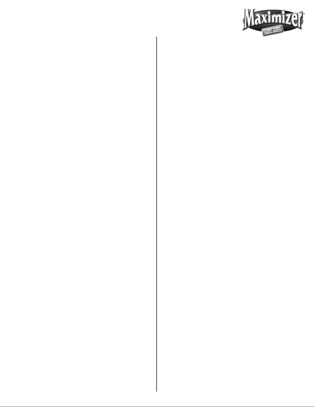
Lane Dividers – (Shelf Accessories)
Lane Dividers with 2-7/8 inch or 3-1/4 inch wide lanes
are available for use on the shelves. The rear of the
lane divider has the shelf hooks inset from the end.
The rear of the shelf should be set lower than the front
so that the shelf slants downward at the rear. The
lane divider is installed by hooking the rear hooks
under the large shelf wire. Flex the lane divider and
hook the wire under the large front shelf wire (See
Figure 1).
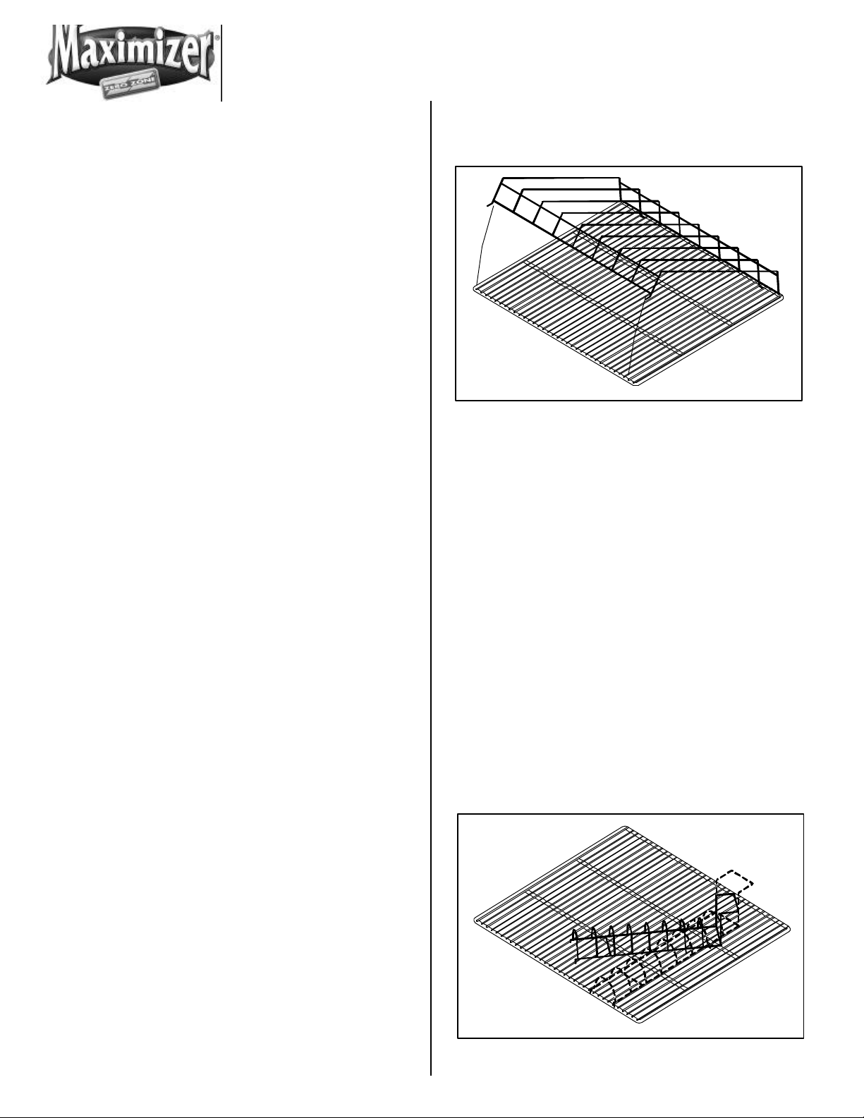
Pre Cut Salad Rack – (Shelf Accessories)
The rear of the rack has two feet that slip under the
shelf wires. The rear of the rack also has a raised wire
stop. The stop is used to provide an air gap between
the product and rear wall.
The rack is installed as follows:
• Set the rack on top of the shelf
• Rotate the rack 45 degrees to the side
• Slide both rear feet under the shelf wires
Figure 2. Salad Rack
SMCP26
Page 5

• Rotate the salad rack back to the original position
while keeping the rear feet under the wires
• Gently squeeze the front of the rack and slide the
two feet between the shelf wires (See Figure 2)
remove the product from the cooler easily. Leave a
1½-inch air gap at the rear of the case. This allows
cool air to travel down the back of the product and
return to the evaporator at the front of the case.
Floral Shelves – (Shelf Accessories)
Glass cantilever floral shelves are available. The
shelves rest on special extra wide shelf brackets.
Cantilever floral bucket shelves are also available. The
bucket shelf bracket is adjustable to allow for shelf
tilting. Before attempting to adjust the shelf bracket,
follow these steps:
• Remove the shelf
• Remove the set screw from the side of the bracket
• Rotate the bracket to the new position
• Install the set screw
• Cantilever shelf standards are factory installed and
must be ordered with a new case
Temperature Control
The cooler temperature is controlled by a low-pressure
control, located in the compressor compartment. The
control is factory-set to maintain a cooler air temperature of 36°F to 41°F. An adjustment knob on top of the
low-pressure control permits fine-tuning of the cooler
temperature.
Products should be placed on the shelves in an orderly
fashion. Whenever possible, leave some room between rows of packages so that chilled air can filter
over and around products.
For proper display, the products should be placed on
edge and slanted to the back so the customer can see
the faces of the packages. Rotate inventory on a
regular basis.
Light Switch
The light switch is located inside the cooler in the
upper right corner of the frame or on the mullion of the
right door. Always turn the lights off when replacing
bulbs.
Coil De-Icing
Periodic de-icing to keep the coil free of excessive frost
for top efficiency is accomplished automatically during
the unit off cycle.
! CAUTION !
To raise the case temperature, turn the adjusting knob
to a higher number. To lower the case temperature,
turn the knob to a lower number. The factory-set
position is at “5”. Maximum cold is “1”.
When properly adjusted the unit should not run continuously. Off cycle time allows the coil to de-ice
automatically. If a coil freeze-up occurs, unsatisfactory
cooler temperatures will result.
Loading The Cooler
The cooler may be loaded with merchandise after the
desired case temperature has been achieved. When
loading the shelves, leave at least 1-1/2 inches between the top of the merchandise and the shelf immediately above it. This allows customers to
ADJUSTING THE CASE TEMPERATURE TO AN EXTREMELY LOW SETTING WILL CAUSE THE UNIT TO
RUN CONTINUOUSLY. IF THIS OCCURS, THE OFFCYCLE DEFROST STAGE WILL NOT OCCUR, RESULTING IN UNSATISFACTORY COOLER OPERATION AND
COIL ICING.
SERVICE
! CAUTION !
DISCONNECT POWER TO THE CASE BEFORE
SERVICING ELECTRICAL COMPONENTS.
SMCP26
Page 6

Evaporator
Lights
The evaporator coil, located at the rear ceiling of the
cooler, is factory assembled with an expansion valve.
To inspect the coil, the coil cover can be removed as
follows. Loosen screws on the underside of the coil
cover until forward edge drops down exposing the
evaporator coil and fan assemblies. While supporting
the cover, unplug the fan electrical connection from
main coil housing. The coil cover can then be removed from the case.
Expansion Valve
A thermostatic expansion valve with adjustable superheat and thermal bulb is mounted to the evaporator
coil. Under certain conditions, it may be necessary to
adjust the super-heat setting for maximum coil effectiveness. To adjust the expansion valve, remove the
coil cover as described for evaporator inspection.
Remove the cap from the bottom of the valve. When
looking up the valve stem, turn the valve stem counterclockwise to open the valve. Turn the valve stem
clockwise to close the valve. Measure the suction line
temperature at the expansion valve-sensing bulb and
compare it to the suction temperature corresponding
to the saturated pressure.
800 milliamp T-12 lamps are standard with these
coolers. There are three lamps in the 2-door coolers
and four lamps in the 3-door coolers. The full height
lamps provide even illumination of the entire case
contents for a better presentation. To ensure maximum component life, always replace with 800
milliamp lamps. Use retainer clips and lamp shields.
To change a lamp, turn off the light switch and remove
the retainer clip located between the socket and end
cap. Carefully push the lamp upward into the springloaded lamp socket to allow the lamp to be removed
Turn the valve stem only ¼ turn at a time and allow
sufficient time for the valve to settle before making any
further adjustments. Replace the valve stem cap after
the valve super-heat has been adjusted.
Evaporator Fans
Air is circulated throughout the cooler with shaft down,
115-volt medium temperature fan motors. These
motors must be operating at all times. The fans are
mounted on the evaporator coil cover. To service the
fans, they are accessed by removal of the coil cover as
described under SERVICE/EVAPORATOR.
Figure 3. Changing A Light Bulb
from the bottom socket. (See Figure 3.) Remove the
end caps and lamp shield for use on the new lamp.
Alternate Lighting – T8
These systems use a lens to direct lamp light output
evenly across the shelves. The bulb used is an Osram
FO32W/41K (4ft). The lens must be removed to access
the lamp. With the lens removed, reach into the fixture
and remove the mylar warning cover. Remove the
lamp socket assembly by carefully pulling away from
the top and bottom retaining
SMCP26
Page 7

clips. Move the foam center seals away from the
electrical connectors. Disconnect the electrical connectors on the top and bottom sockets by depressing
the locking tab and pulling away from the socket.
Detailed information is contained in the door instruction booklet.
check to make sure the circuit breaker is switched to
the “on” position. A red bar below the word “off”
indicates the circuit breaker has tripped. To reset the
breaker, switch it off and then on. If the circuit breaker
continues to trip, contact a technician to repair the
case.
Note: The ballast for this system is located in the door
mullion.
Compressor Access Panel (Grill)
Remove the compressor access panel located at the
front bottom of the cooler by removing the screws at
the bottom ends of the panel. Drop the panel down
and pull out. The panel must be removed before any
service work can be done to the compressor, light
ballasts and pressure control.
Compressor
A 115 volt, 1 phase, 60 Hz, compressor is mounted
below the cooler. The condensing unit is equipped
with liquid line and suction service valves for refrigeration technician service.
Light Ballast
PREVENTIVE MAINTENANCE
1. Clean condenser fins at least once every 6 months
in order to achieve maximum cooling efficiency.
More often if cooler is in a particularly dirty or dusty
location or near an entrance or check out.
2. Keep floor drain pan and condensate drain tube
clear of debris.
The 2-door cooler has one (1) three-lamp ballast.
The 3-door cooler has two (2) two-lamp ballasts. They
are located in the galvanized electric box located at
the right side of the compressor compartment at the
back.
To remove the electric box cover, remove the sheet
metal screws from the bottom of the ballast box and
slide the cover upwards to disengage the top flange.
The cover can then be removed for ballast inspection
or replacement.
Circuit Protection
The 3-door unit is equipped with one 20-amp circuit
breaker. The circuit breaker is located in the front of
the electric box. The circuit breaker protects the fan,
door and light circuits. If these circuits fail to work,
SMCP26
Page 8

SMCP26 SPECIFICATION SHEET
(INCHES)
(INCHES)
FEET
AMPS
RLA
Front Elevation
Front Elevation
2SMCP26
3SMCP26
Top View
Shown in Section
Side View
2SMCP26
Top View
Shown in Section
3SMCP26
OUTSIDE DIMENSIONS
MODEL WEIGHT
(w/shelves) W H D W H D CAPACITY AREA SQ. FT.
2SMCP26 640 60 78 5/8 33 1/4 55 59 7/8 29 1/2 43.6 43.5
3SMCP26 856 87 78 5/8 33 1/4 82 59 7/8 29 1/2 61.4 65.3
ELECTRICAL (OPTIONAL)
MODEL INCOMING SUPPLY
2SMCP26 115-1 PHASE-60 HZ. 20 14.02 1/2 R22 2 1/2
3SMCP26 115-1 PHASE-60 HZ. 25 17.6 1/2 R22 2 1/2
INSIDE DIMENSIONS
MIN
CIRCUIT
AMPS
NET CUBIC
NET SHELF
CHARGE
H.P. REF.
Zero Zone Inc. l 110 N. Oakridge Dr.
North Prairie, WI 53153-9792
1-800-247-4496 l FAX: 1-262-392-6450
www.zero-zone.com
All specifications are subject to change without notice.
(LBS.)
SMCP26
Page 9

SMCP26
Page 10

SMCP26
Page 11

1. Limited Warranty. ZERO ZONE, INC. (“Seller”) hereby warrants that any products manufactured by it and sold under this Warranty shall be free for a period of one year from the date
of shipment, from defects in material and workmanship which, under normal use and
service would render such products unusable or unserviceable. The obligation of Seller
under this Warranty shall be limited to the repair or replacement of any parts that the Seller
determines are defective. This Limited Warranty does not cover labor, freight, transportation
or other charges incidental to replacement or repair. Parts returned to Seller must be returned freight prepaid and replacements will be returned to the Buyer freight collect.
2. Motor Compressor Extended Warranty. Seller hereby warrants with respect to any motor
compressor sold under this Warranty, exclusive of any and all parts of the condensing unit
assembly thereof, that such motor compressor shall be free from defects in material and
workmanship for a period of four (4) years from the date of the expiration of the one year
Warranty provided by the manufacturer of such motor compressor, if the Buyer purchases
said Warranty at the time of equipment purchase. In the event the motor compressor is
not free from defects in material and/or workmanship during such four year period, Buyer
must purchase a replacement for the defective motor compressor and obtain whatever
salvage credit may be available from the manufacturer thereof. Upon receipt by Seller or
written notice from Buyer of compressor, Seller will issue a purchase or a refund, at Seller’s
option, for an amount of the salvage credit. All labor and shipping charges incurred in
connection with such replacement shall be the sole obligation of the Buyer.
3. Product Not Manufactured by Seller. The written Warranty, if any, provided by the manufacturer of any part of the refrigeration unit sold by Seller to Buyer, but not manufactured by
Seller, is hereby assigned to Buyer. However, Seller makes no representation or Warranty
regarding the existence, validity or enforceability of any such written Warranty.
4. LIMITATION AND EXCLUSION OF WARRANTIES. THE WARRANTIES SET FORTH HEREIN ARE
EXCLUSIVE AND IN LIEU OF ALL OTHER WARRANTIES AND REMEDIES WHATSOEVER, INCLUDING BUT NOT LIMITED TO, IMPLIED WARRANTIES OF MERCHANTABILITY AND/OR FITNESS FOR
A PARTICULAR PURPOSE.
5. Consequential Damages. Notwithstanding anything to the contrary set forth in this Warranty Certificate, Seller shall not be liable for any incidental or consequential damages
arising out of, or directly or indirectly caused by a defective part sold by Seller, including but
not limited to, costs arising from the replacement of the part, loss of gas or product, or any
damage to person or property, whether as a result of Seller’s negligence, breach of contract, breach of Warranty or otherwise.
Model No._________________________ Serial No.______________________
SMCP26
 Loading...