

Page 1
U
D
y
F
INSTALLATION
AND OPERATING INSTR
CTIONS
ispla
reezers
Zero Zone, Inc. 110 N. Oakridge Dr. North Prairie, WI 53153-9792
1-800-247-4496 FAX: 1-262-392-6450 www.zero-zone.com
Page 2

TABLE OF CONTENTS
SUBJECT
GENERAL INFORMATION 2
INTRODUCTION 2
INSPECTION 2
LOCATION 2
INSTALLATION 2-6
LEVELING 2-3
JOINING FREEZERS 4
DRAIN LINE 5-6
CART BUMPER 6
REFRIGERATION 7-8
GENERAL 7
REFRIGERANT PIPING 7
TEMPERATURE CONTROL 8
TEMPERATURE CONTROL ADJUSTMENT 8
LEAK CHECK-EVACUATION-CHARGING 8
ELECTRICAL 8-9
DEFROSTING 9-11
GENERAL 9
ELECTRIC DEFROST 9
GAS DEFROST 10
LIMIT THERMOSTAT 10-11
USER INFORMATION 11-12
CLEANING 11
SHELF LOCATION 11
LOADING THE FREEZER 11
LIGHT SWITCH 12
LIGHTING 12
SERVICE 12-13
CART BUMPER 12
EVAPORATOR 12
EXPANSION VALVE 12
DEFROST HEATER ELEMENT 13
RMZC30XL HEATER ELEMENT REMOVAL 13
EVAPORATOR FANS 13
RMZC30XL FAN REMOVAL 13
ELECTRICAL SCHEMATICS 14
- 1 -
REVISION A
10/30/02
Page 3

GENERAL INFORMATION
Introduction
The information contained in this manual pertains to
the following Maximizer display freezer: RMZC30XL.
This case is used for merchandising frozen food or ice
cream. The RMZC30XL has 30-inch wide doors and
utilizes the revolutionary new S-coil. Zero Zone, Inc.
of level conditions will result in reduced performance,
and will make the installation more difficult.
When located next to a wall, or backed up to another
case line-up, the cases should be positioned to allow
a minimum (4) inch space behind the back of a unit.
This will allow necessary air to circulate behind the
unit.
has made every effort to produce refrigeration
equipment of the highest quality using state-of-the-art
components.
This display freezer was designed to operate in an air-
conditioned store where the temperature is
maintained at 75°F or lower and the relative humidity
is 55% or lower.
Inspection
This display freezer was carefully factory tested,
inspected and properly packaged to ensure delivery in
the best possible condition. The equipment should be
uncrated and checked for damage immediately upon
delivery.
ALL CLAIMS REGARDING SHIPPING DAMAGES MUST
BE FILED WITH THE CARRIER/TRANSPORT COMPANY.
DO NOT FILE CLAIMS WITH ZERO ZONE, INC.
(The carrier/transport company will supply the
necessary report and claim forms.
Location
This freezer must not be installed where it will be
exposed to direct sunlight or near a source of radiant
heat.
INSTALLATION
DISCLAIMER,
Installation of the case; including proper footings &
stable support, leveling, drain plumbing,
refrigeration and electrical tie-ins, application of
local building codes, etc. are in whole the
responsibility of the store and the contractor/s
performing these jobs. Zero Zone, Inc. will not
accept responsibility for improper installations.
Leveling
Refrigeration equipment must be installed level and
plumb to allow efficient operation of the refrigeration
coils and complete drainage of defrost condensate
(water). Since a level area is seldom available, the
following steps are recommended to insure a level
installation.
1. Carefully, measure off and mark on floor with the
dimensions of the case line-up. (Check blueprints
– See Figure 1A)
2. Snap a chalk line at the locations for the front and
back positions of the base rails.
Be certain that the floor under the installation is of
sufficient strength to support a fully loaded case. Out
- 2 -
REVISION A
10/30/02
Page 4
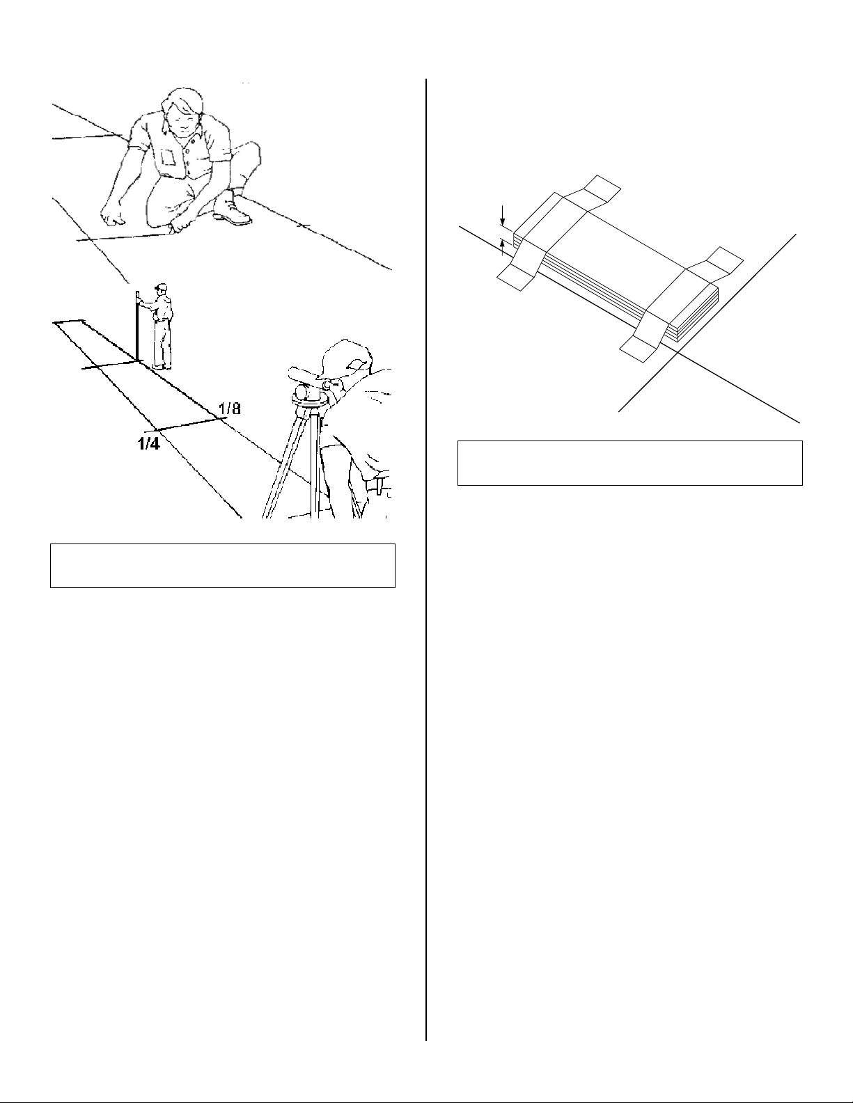
7. Place the required number of shims (supplied) at
each joint (front and back) to equal the highest
FIGURE 1A
MARKING AND LAYOUT
3. Mark locations of all joints (front and back).
4. Using a transit or laser, find the highest point
along both base rail position lines. Using the high
point as a reference, mark the difference directly
on the floor to each joint (front and back).
5.
If a transit or laser is not available, a water level
can be used to mark reference elevation points.
Water levels can be purchased from a contractor
supply house or hardware store for a minimal
cost.
6. A string level can also be used to mark elevation
points. The string level should only be used on
short line-ups to avoid problems with string sag.
point. Tape all shims in
place (See Figure 1B).
3/8"
FIGURE 1B
LEVELING AND SHIMMING
8. Be sure to place shims under all the bases where
required. Do not leave a base unsupported.
9. Using a spirit (bubble) or laser level check the
installation as you go. The case
from front to back and side to side. Install
case
at the highest point first, if part of a line-up.
should be level
the
- 3 -
REVISION A
10/30/02
Page 5
Joining Freezers
This reach-In freezer has been engineered for
continuous line-up. This means that any number of
cases can be joined together to create the desired
length. Reach-In freezers are built on permanent steel
skids to promote easy installation. The cases can be
moved by using case jacks, with a fork truck
(Telehandler) or with Johnson Bars.
To install Reach-Ins, perform the following steps:
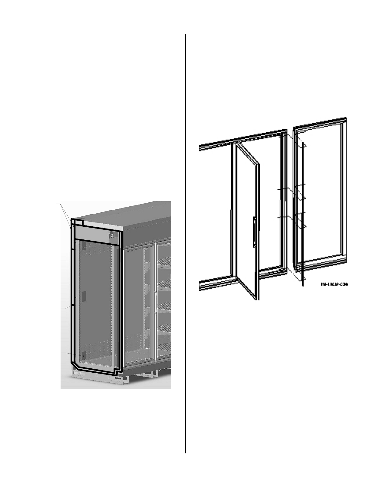
1. Set the first Reach-In into the desired position and
level it. Run two (2) 3/8 inch diameter beads of
Butyl caulk 1/2 inch in from both the inner and
outer surfaces of the case end. (See Figure 2A)
2. Push the second Reach-In against the end of the
first. Level the second Reach-In. Remove the left
and right end floor covers and the rectangular
pocket hole covers, accessing the holes in the end
panels of each freezer as shown (Figure 2A).
Install tee strips between the doorframes at case
joints (See Figure 2B) Use the special screws and
nuts provided.
APPLY TWO (2)
CONTINUOUS 3/8"
DIAMETER BEADS
OF BUTYL CAULK
ALONG THE
PERIMETER OF BOTH
MATING ENDS
(AS SHOWN)
THOUGH SHOWN IN
BLACK, THE COLOR OF
THE BUTYL CAULK
MAY BE WHITE OR
CREAM DEPENDING
UPON THE COLOR OF
THE CASES TO BE
ALSO APPLY A SHORT
BEAD OF CAULK TO
EACH JOINT WHERE
THE INSULATED
PANELS MEET AT A
SEAM. THREE (3)
POCKET COVERS,
THREE (3) PER END
JOINED
PLACES
FIGURE 2B
INSTALLING TEE STRIPS
3. Start the joining bolts, but do not tighten them.
Begin tightening the bolts at the top rear, working
down the back of the case and up the front
FIGURE 2A
CAULKING THE CASES
making sure that the front faces of the cases are
flush (See Figure 2C). Pay attention to the
alignment of the doorframes.
- 4 -
REVISION A
10/30/02
Page 6
1-1/2" LONG HEX HD CAP
SCREWS AT REAR
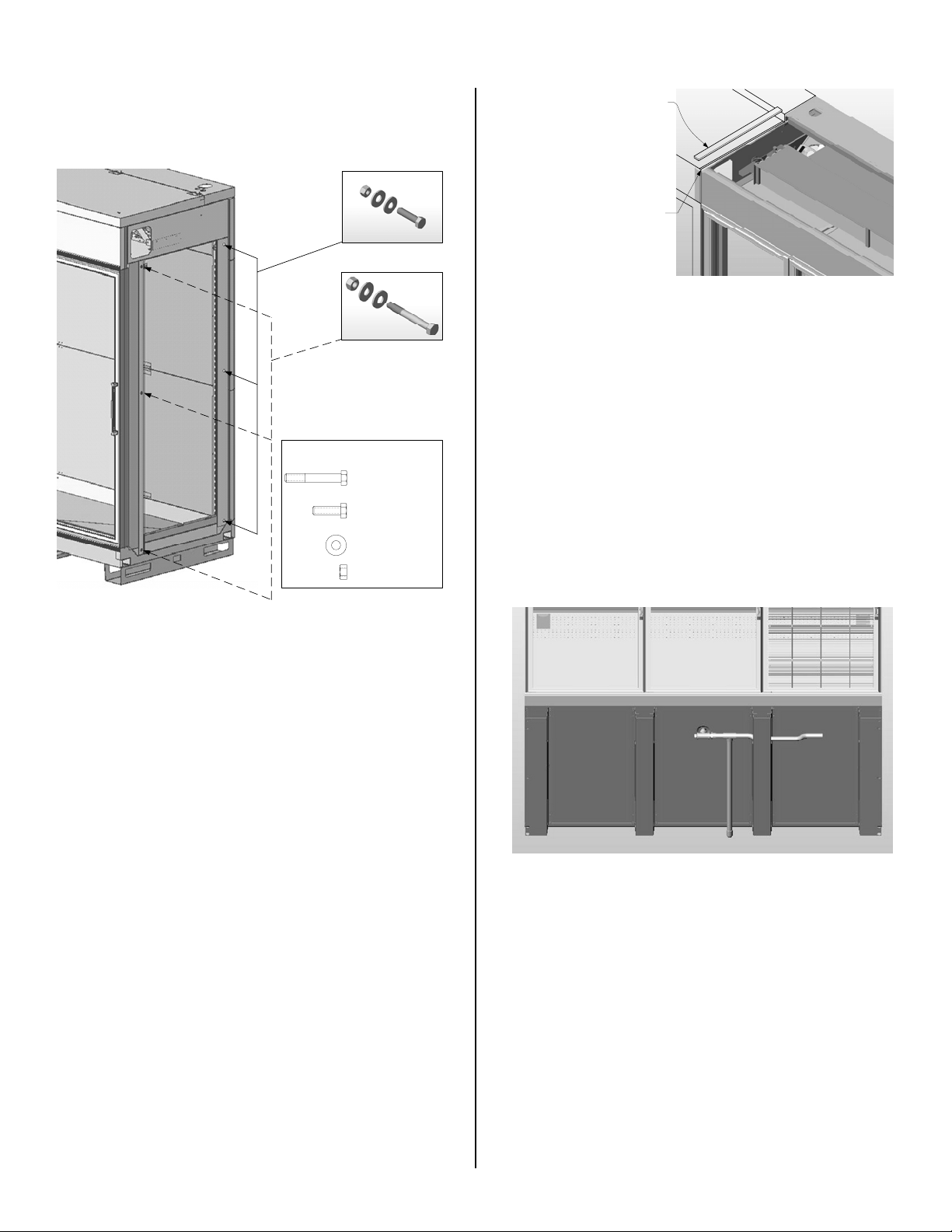
ROOF GASKET MATERIAL (WHITE OR BLACK)
PEEL THE DOUBLE STRIP OFF THE BACK OF
THE GASKET AND APPLY IT SUCH THAT AN
EQUAL AMOUNT OF GASKET IS LOCATED
ON BOTH CASES. START THE GASKET AT
THE JOINT WHER E THE ROOF PANEL MEETS
THE HINGE PANEL AND RUN IT FORWARD
TO THE FRONT OF THE CASE.
1-1/2" WIDE x 3/16" THICK
APPLY THE GASKET SUCH THAT IT
COVERS THE SEAM COMPLETELY
BETWEEN THE TWO CASES
(DO NOT RUN THE GASKET DOWN THE
FRONT PANEL)
FIGURE 2D
3" LONG HEX HD CAP SCREWS
AT FRONT
INSTALLING ROOF GASKET
Drain Line
FASTENERS REQ'D TO JOIN A
ZERO ZONE® RMZCXL CASE
(3) 3/8"UNC x 3" LONG
HEX HD CAP SCREW.
PART No. 64-0025
(3) 3/8"UNC x 1-1/2" LONG
HEX HD CAP SCREW.
PART No. 64-0080
(12) 3/8" FLAT WASHERS
PART No. 64-0034
(6) 3/8"UNC HEX NUTS
PART No. 64-0064
The drain is located at the center of the freezer in the
floor pan. The drain can be reached by removing the
center floor covers. The 1 inch PVC drain outlet is
located at the center front of the freezer behind the
kick plate. Figure 3A shows this location (the case is
tilted backward to clearly illustrate).
FIGURE 2C
INSTALLING JOINING BOLTS
4. Each case joint at the top requires a 1-1/2 inch
wide roof gasket to merge the seam between the
two (2) cases. Installation of this gasket is very
important. Place the gasket back to where the
hinge panel begins and run it all the way forward
to the edge of the front panel. Cut it flush with the
front panel. (See Figure 2D)
FIGURE 3A
DRAIN LOCATION
Install a tee to the outlet pipe. Next, connect the line
that returns to the rear of the case to connect the
defrost drain line. Then connect PVC drain trap to the
tee. The drain line must be pitched a minimum of (1)
inch per lineal foot. Connect the flexible defrost drain
- 5 -
line to the barbed end of the lower drain assembly.
Using the hose clamp, secure the flexible tubing to the
barbed fitting. The tee, drain trap, and plug are
REVISION A
10/30/02
Page 7

supplied standard with the case. The drain assembly
is supplied such that it can be routed to either the right
or left of the case. Dry fit all your drain parts first to
ensure they are located properly. (See Figure 3B)
DO NOT FORGET TO GLUE THE SLIP FIT PVC PARTS
TOGETHER USING PVC CEMENT.
MAKE SURE ALL PVC SLIP
FIT JOINTS ARE GLUED,
USING PVC CEMENT
THIS PORTION OF THE
DRAIN IS FIXED WITHIN
THE FLOOR OF THE CASE
THIS GROUP OF DRAIN
PARTS CAN BE FLIPPED
TO THE OPPOSITE SIDE TO
FACILITATE A LEFT-HAND
DRAIN IF NECESSARY
FIGURE 3B
DRAIN ASSEMBLY
Cart Bumper
The cart bumper should be installed at the bottom
front of the case. (See Figure 4A) The assembly is
BUMPER
SPLICE
CART BUMPER
& BUMPER
SUPPORT RAIL
KICK RAIL
FIGURE 4A
BUMPER JOINING STRIP
USING THE HOLE
PROVIDED, RIVET
THE SPLICE TO THE
TOP EDGE OF THE
FRONT PANEL USE
THIS TO COVER THE
UPPER SEAM
BETWEEN THE TWO
(2 ) CASES.
adjustable to compensate for uneven floors.
Center and hook the bumper assembly on the
hangers provided.
In continuous line-ups, place a kick plate joint strip at
each joint. On case ends, lineup an end kick plate
with the front mounting holes. Fasten the rear of the
end kick plate to the case using TEK screws.
A bumper and top splice joint strip can be installed
over the bumper and the seam between the cases.
(See Figures 4 A and 4B for details)
UPPER SPLICE
APPLY (3) DABS OF
CAULK/ADHESIVE
TO THE FACE (NEAR
THE EDGE) OF THE
UPPER PANEL
FIGURE 4B
UPPER JOINING STRIP
- 6 -
REVISION A
10/30/02
Page 8

REFRIGERATION
General
Unless otherwise specified, the liquid and suction line
connections are made on the outside of the case at
the top/rear of the case. If the case is an electric
defrost, the connections will be on the left end of the
case. If the case is hot gas defrost, the connections
will be on the right end of the case.
Alternate locations are available depending on how
the case was ordered from the factory. After all the
connections have been made, all refrigeration egress
holes (through the case) must be sealed completely.
The holes should be filled using expanding urethane
foam (i.e. Great Stuff®); and then covered with a layer
of Perma-gum Strip Caulk to prevent moisture
infiltration.
Refrigerant Piping
Correct refrigeration line sizing and installation is
essential for proper system operation. The following
tables (Table 1) list R502, R404A, R507, and R-22 line
sizes for different combinations of frozen food and ice
cream freezers. This information is also available by
contacting Zero Zone, Inc. A P-trap must be installed
at the bottom of all vertical suction risers.
When two or more freezer sections are connected to
The compressor should be installed as close as
possible to the freezers to reduce pressure drop. If the
compressor is located above the freezer, check the
refrigerant line size tables (Table 1) of this manual to
determine the riser line size. Or contact Zero Zone,
Inc. directly for correct sizing information. Install a trap
at the bottom of the riser. Use a flexible connection
(vibration eliminator) between the suction line and
compressor.
The suction and liquid lines may be joined together to
form an external heat exchanger. Insulate the
refrigerant tubing for at least 20 feet from the freezer
outlet.
The best location for the liquid line drier is inside the
freezing compartment. However, it may be installed
near the compressor for easy maintenance. Install a
moisture indicating sight glass at the outlet
drier.
end of the
one compressor, the main liquid and suction line for
the group should be run through the freezers and
brought out through the refrigeration outlet of one
freezer only. Standard installation procedures
recommend one riser per circuit, per system, for hot
gas defrost setup. This is available as a factory
installed option. A piping chase allows the refrigerant
lines to be run case to case out of the upper left or
right of the end frames.
- 7 -
Temperature Control
REVISION A
10/30/02
Page 9

A low pressure or temperature control can be used to
The sensing bulb/probe is located under the coil cover
control freezer
temperature. The control should be
selected with adequate contact capacity for the
switching load. In rack systems, an evaporator
pressure-regulating valve may be used to control the
evaporating temperature.
CONDENSING UNIT PRESSURE SETTINGS
FROZEN FOOD
PRESSURE (psig)
R-22 R502 R404A R507
CUT IN 21 23 30 31 -2
CUT OUT 11 16 18 18 -8
ICE CREAM
PRESSURE (psig)
R-22 R502 R404A R507
CUT IN 15 21 22 23 -10
CUT OUT 6 11 12 13 -16
RETURN AIR
TEMPERATURE (ºF)
RETURN AIR
TEMPERATURE (ºF)
FIGURE 5A
TEMPERATURE CONTROL
RACK EPR SETTINGS
(SATURATED COIL TEMPERATURE)
MODEL NUMBER FROZEN FOOD ICE CREAM
RMZC30XL -15º F -23º F
FIGURE 5B
RACK EPR SETTINGS
The settings (See Figures 5A and 5B) are approximate
due to variations in gauge accuracy, differences in
compressor efficiency, line pressure drop and super
heat settings. Before making adjustments for store or
stocking conditions, NOTE: (make sure the
heat
is set between 6º F and 10º F).
super-
Temperature Control Adjustment
When factory installed, the temperature control is
located toward the top right end of the freezer inside
the freezer compartment and in front of the
honeycomb (discharge air) case (in front of the coil).
- 8 -
inside the cabinet. It should be wired in series with the
low-pressure (L.P.) control. The wiring diagram (Figure
NN) shows use
of the thermostat in a pump down
system. (Figure NN) shows a standard type of
temperature control
.
Leak Check-Evacuation-Charging
After all of the refrigeration piping and system
components have been assembled, the entire system
must be pressurized and checked for leaks. Use
nitrogen and refrigerant vapor to check for leaks. A
Halide leak detector or an electronic leak detector is
recommended.
If the system is sealed, evacuate with a deep
vacuum pump. Triple evacuation to a
minimum of 500 microns and nitrogen sweep
is recommended. After the system has been
thoroughly evacuated of all moisture and noncondensable gas, charge the system with the
proper refrigerant, using “ hi-side/low-side”
charging techniques.
ELECTRICAL
Figure 13 shows the typical wiring diagram for a
freezer equipped with electric defrost. Figure 14
shows the typical wiring diagram for a freezer
equipped with hot gas defrost. Each case is provided
with a wiring diagram located near the electric box
that shows the exact wiring of the case.
There are many control options available for multiple
case defrost systems. Wiring diagrams and
instructions can be obtained by calling Zero Zone`s
Service Department.
REVISION A
10/30/02
Page 10

External wiring should be sized according to the
generally have the pressure switch built into the time
amperage rating stamped on the serial plate. The
serial plate is located on the ceiling inside the left-
hand door. All internal wiring has been done at the
factory. It has been terminated in the electrical box
located
at the top and rear on the right end of the
case. A terminal block has been used to simplify field
connections.
The line side of the contactor/relay is energized with
115 volts at all times. The 115-volt loads in the freezer
are energized at all times except during defrost and
during post-defrost pulldown. For electric defrost the
208/230 volt defrost element is OFF at all times except
during defrost. The time clock is in operation at all
times. The drain line heater is wired at 115-volt and is
on at all times. If a Hot Gas Solenoid and/or a roof
mounted anti-sweat kit are installed, these too will run
clock. A time clock can be purchased from Zero Zone
or from a local refrigeration supply house.
Temperature termination of defrost is strongly
recommended on Zero Zone cases.
BLUE
YELLOW
OPEN ON FALL
OPEN ON RISE
YELLOW
BLUE
RED
RED
DEFROST
TERMINATION
STAT (50-55ºF)
SETTINGS
RED/YELLOW CLOSE ON RISE
RED/BLUE CLOSE ON FALL
DIFFERENCIAL SLIDER CONTROL
(LOCATED BEHIND COVER)
LINE TO PROBE
at all times on 115-volt.
Note: All wiring must comply with the National
Electrical Code and all local codes.
DEFROSTING
General
Periodic defrosting to keep the coil free of frost is
accomplished automatically by a time clock used in
conjunction with an electric, hot gas, or reduced
temperature gas injection defrost system. The most
reliable and efficient defrost system for a single case
uses a time
termination device. Time clocks can be purchased
that terminate on coil temperature or case coil
pressure. These clocks have the ability to match the
defrost time to the frost load on the coil. Coil
temperature is sensed by the defrost temperature
termination thermostat supplied as standard on all
Zero Zone freezers. Pressure terminating clocks
clock that incorporates a defrost
FIGURE 6
JOHNSON TYPE CONTROL
Electric Defrost
When the pin in the 24 hour dial reaches the TIME
arrow, the clock will trip and the defrost cycle will start.
At that time, the clock will stop the compressor,
energize the 208/230 volt defrost heater, and
energize the normally closed 208/230 volt contactor
or relay. This de-energizes the 115-volt fans, lights,
and door set anti-sweat heaters.
After the defrost period, the compressor will operate.
When the coil temperature drops below +5°F, the fan,
light and anti-sweat heater limit thermostats will close,
starting the fans, lights and anti-sweat heaters.
- 9 -
REVISION A
10/30/02
Page 11

Gas Defrost
Several types of gas defrost methods in conjunction
with time actuated, time or temperature terminated
defrost timers can be used to defrost the evaporator.
The refrigeration system designer and installer are
responsible for correct line sizing for effective gas
defrost and liquid return from the freezers. Sizing and
component selection depend on the type of defrost,
size, and location of high side refrigeration system.
Zero Zone freezers equipped for hot gas defrost
consist of a side port, distributor and check valve for
coil defrost, and a check valve and serpentine coil
attached to the bottom of the pan to ensure pan and
drain defrost.
Liquid and suction line connections are made outside
the case, through the refrigeration access hole located
at the top right rear corner of the freezer.
The timer starts the gas defrost cycle by energizing a
solenoid, reversing valve, or directional valve. The gas
is injected from the source into the suction line of the
evaporator to be defrosted. The gas flows into the
serpentine coil attached to the floor of the case and
into the evaporator. Condensed liquid leaves the
evaporator through the side port distributor, through a
check valve into the liquid line.
the serpentine passes through a check valve into the
liquid line. Refer to the defrost frequency and
termination recommendations that follow on (Figure
9).
TEMPERATURE AND PRESSURE TERMINATION
REDUCED
FREQUENCY 1 1 1
TEMPERATURE 55º F 55º F 55º F
TEMPERATURE
GAS DEFROST
Liquid condensed in
HOT
GAS
DEFROST
ELECTRIC
DEFROST
PRESSURE
FAIL-SAFE
TIME (minutes)
DRAIN/DRIP
TIME (minutes)
TIME ONLY TERMINATION (not recommended)
TIME (minutes) 14-22 12-20 40-45
DRAIN/DRIP
TIME (minutes)
SATURATED SUCTION PRESSURE
EQUAL TO 50º F
40 30 60
3-5 3-5 0
3-5 3-5 0
FIGURE 9
DEFROST FREQUENCY & TERMINATION
Temperature Termination Required
Refrigeration technician should recheck coil
condition after one week of operation to be certain
that the frequency and duration of defrost is
adequate for the particular store and locality. For
example, if defrost voltage is below 200 volts,
additional fail-safe time may be required.
When using time terminated defrost, temperature
terminated thermostat should be wired in series
with the defrost heater.
Temperature termination thermostats may be
wired in series for multiple evaporator
installations.
Limit Thermostat
Each freezer has factory set limit thermostats (Klixons)
attached to the return bends of the coil on the right
end of the freezer to regulate the operation of the
evaporator fans, freezer lights, and anti-sweat
heaters.
OPERATION OF THE LIMIT THERMOSTATS CAUSES
THE EVAPORATOR FANS, FREEZER LIGHTS, AND
ANTI-SWEAT HEATERS TO REMAIN OFF UNTIL THE
COMPRESSOR IS OPERATING AND THE COIL
TEMPERATURE IS BROUGHT BELOW THE
- 10 -
THERMOSTAT CUT-IN SETTING (+5ºF). SUPERHEAT
REVISION A
10/30/02
Page 12

MUST BE SET CORRECTLY FOR PROPER THERMOSTAT
case temperature and proper control operation. While
OPERATION
When the freezer first operates, the fans and lights
may cycle on and off a few times until coil temperature
stays below +5ºF.
USER INFORMATION
Cleaning
The freezer should be thoroughly cleaned before start-
up and routinely thereafter to maintain a clean
appearance. Use mild detergent and warm water
(never an abrasive cleaner) to wipe out the inside of
the freezer. Wash down all glass doors with glass
cleaner. Clean interior glass reduces fogging and
increases visibility. The freezer will remain bright and
sparkling with just a few minutes of cleaning each
week. Internal components can be cleaned after
removal of access panels. The case drain should be
loading the shelves, leave at least 1-1/2 inch between
the top of the merchandise and the shelf above it so
the customer can remove the
inch space
allows an air curtain on the top of the
merchandise. The 1-1/2
product. Product should not exceed load limits (see
Figure 10).
GENERAL GUIDELINES FOR STOCKING A ZERO ZONE® RMZCXL CASE
1-1/2" GAP BETWEEN THE PRODUCT
AND THE CEILING (TO ALLOW
CLEAR AIRFLOW TO THE REAR DUCT)
1-1/2" GAP BETWEEN THE PRODUCT
AND THE SHELF ABOVE (TO ALLOW
EASY STOCKING AND
UNSTOCKING OF THE PRODUCT)
DO NOT OVER STOCK
THE SHELF WHEREBY PRODUCT
IS NOT RESTING FULLY ON THE
SHELF.
INDIVIDUAL SHELF LOADS
NOT TO EXCEED 275LBS
(125kg)
regularly cleared of debris and price tags.
Note: Do not use high-pressure water or steam to
clean the interior.
Shelf Location
The shelves are adjustable in 1- 1/2inch increments
and may be located in any position for best display
advantage. The shelves also come with a tilt feature
whereby the outer set of hooks can be used on the
shelf brackets to angle the shelf downward. This may
be a desired feature when product needs to roll /slide
ahead for stocking.
Be sure shelf brackets are completely seated
before installing the shelf.
Loading the Freezer
The freezer may be loaded with merchandise after it
has been operated for at least 24 hours with correct
ENSURE ALL SHELVES ARE
SECURELY LOCATED ON
THEIR RESPECTIVE SHELF
BRACKETS
DO NOT BLOCK RETURN
AIR GRILL
FIGURE 10
LOADING A FREEZER
Light Switch
The light switch is located on the mullion by the hinge
side rightmost door. Turn the light switch off during
the initial freezer temperature pull-down to prevent the
freezer lights from cycling off and on. Always turn the
lights off when replacing lamps.
- 11 -
REVISION A
10/30/02
Page 13

effectiveness.
Typical super heat settings are
Lighting
T8 lighting is standard on the RMZC30XL. These
systems use a lens to direct the light output evenly
across the shelves.
In order to access the lamp the lens cover must be
removed. Details of this can be located in the door
instruction booklet.
SERVICE
Cart Bumper
The cart bumper must be removed to gain access to
the drain clean out. Disassemble the bumper and kick
rail by removing the 2 or 3 metal screws located in the
kick rail. The bumper assembly can be lifted up and
removed from the case. The kick plate can be
removed, exposing the drain. (Figure 4A shows the
bumper assembly)
Evaporator
The evaporator coil, located at the top of the freezer, is
factory assembled with distributor and expansion
valve. Additional items (such as hand valves, air
filter/dryers, sight glass, etc.) may be attached to the
system depending upon the options selected. To
inspect the entire coil, open the roof panel and the
front of the coil should be directly visible.
Expansion Valve
Do not adjust the expansion valve, unless you are
qualified to do so. Except where otherwise specified,
an externally equalized thermostatic expansion valve
with pressure limiting charge adjustable super-heat
and thermal bulb is mounted to the evaporator coil.
between 6°F and 10°F
. To adjust the expansion
valve, open the roof panel. To the far left of the coil,
the valve should be visible. Remove the cap from the
bottom of the valve. When looking at the valve stem
end, turn the valve stem counterclockwise to decrease
super heat. Turn the valve stem clockwise to increase
super heat. Measure the
suction line temperature at
the expansion valve-sensing bulb and compare it to
the suction temperature corresponding to the
saturated pressure at the coil.
CAP
EXPANSION
VALVE
FIGURE 11
EXPANSION VALVE LOCATION
Turn the valve stem only 1/4 turn at a time and allow
sufficient time (20 to 30 minutes)
for the valve to
settle before making any further adjustments. Replace
the valve stem cap after the valve super-heat has
been adjusted. BE CERTAIN THE VALVE STEM CAP IS
WIPED DRY FIRST.
CAUTION!
DISCONNECT POWER TO THE CASE BEFORE
SERVICING ELECTRICAL COMPONENTS
Defrost Heater Element
Adjust the super-heat setting for maximum coil
- 12 -
REVISION A
10/30/02
Page 14

The heater element is located under the coil. The
electric wire leads are connected in the electrical box
on the top right rear of the case.
RMZC30XL Heater Element Removal
Shut off the power to the case.
of the defrost heater wire from the relay/coil inside the
electrical box.
To remove the defrost element, open the roof of the
case and expose the coil area. At either end of the
coil there is a screw that locks the heater bracket,
relative to the coil. Remove these screws. Once
removed, the heater bracket should slide towards the
front of the case. Once clear of the coil, the heater can
be removed by unscrewing the clips that lock the
heater to the heater bracket. Lift the heater free of the
heater bracket and feed the wires back through the
conduit at the top of the case.
Disconnect the leads
Evaporator Fans
Air is circulated throughout the freezer with 115-volt
low temperature fan motors. These motors must be
all operating at all times except during defrost.
RMZC30XL Fan Removal
Shut off the power to the case.
the case and expose the coil area. At the rear of the
coil, there is a fan shroud. This fan shroud may either
show a hinged cover, or may consist of several slip
covers. Remove any screws that hold down the
covers. Once the cover is opened/removed the fan
motors should now be exposed.
Unplug fan from fan power supply plug located on the
rear face of the fan housing.
Remove the two (2) mounting screws on either side of
the fan bracket and remove the fan assembly from the
fan housing.
Open up the roof of
- 13 -
REVISION A
10/30/02
Page 15

FIGURE 13
ELECTRICAL SCHEMATIC – ELECTRIC DEFROST
- 14 -
FIGURE 14
ELECTRICAL SCHEMATIC – HOT GAS DEFROST
REVISION A
10/30/02
Page 16

- 15 -
REVISION A
10/30/02
Page 17

PRELIMINARY
.
RMZC3OKL SPECIFICATION SHEET
CASE
SIZE
2RMZC30XL
3RMZC30XL
4RMZC30XL
5RMZC30XL
MODEL
NUMBER
2RM ZC30XL
3RM ZC30XL
4RM ZC30XL
5RM ZC30XL
CAPACITY
SPEC1 FICATIONS
CAPACITIES
USABLE
CAPACITY
66
99
131
1
64
FAN
AMPS
0.68
1
.36
1.70
2.04
T-8 LIGHTS
CASE
SIZE
2RMZC30XL
3RMZC30XL
SHELF
25
25
.25
DEPTH
4RMZC30XL
5RMZC30XL
*WEIGHT BASED
WITHOUT
ENDS,
SINGLE
25
ELECTRICAL SPECIFICATIONS
ANTHONY
ANTI-SW EAT
HEATERS
AMPS
4.85
7.05
9.25
10.86
AMPS
1.89
2.50
3.13
3.75
ELM
ANTI-SW EAT
HEATER
AM PS
ANTHONY DOORS
2.43
3.34
4.35
5.37
WEIGHT
POUNDS*
945
1,315
1,76
2,244
ON
UNCRATED CASES
AND FULLY SHELVED.
END
WEIGHT:
65 POUNDS
DEFROST
HEATER
AMPS
208V/1/60HZ.
6.73
10.10
13.46
16.83
IN
1
DRAIN
HEATER
AM PS
4.57
6.25
7.93
9.62
MODEL
NUMBER
2RM ZCJOXL
3RM ZC3OXL
4RM ZC30XL
5RMZC30XL
RMZC30XL
WIOPTIONAL
ELM DOORS
Zero Zone,
Inc.
North Prairie,
1
-800-247-4496
BTUIHR
FOOD
3,550
5.325
7,100
8,875
DEDUCT
275
BTUHRIDOOR
.
1
10
W1
531 53-9792
.
FAX:
www.zero-zone.com
'STANDARD FOR CASE IN A LINE-UP
VOLTAGE: 115 VOLTS 1 PHASE 60 HZ.
BTU/HR ENERGY REQUIREMENTS:
BTUIHR
ICE CREAM
3,870
5,805
7,740
9,675
DEDUCT
325
BTUHRIDOOR
N.
Oakridge
262-392-6450
Dr.
BTUIHR RATING BASED ON T-8 LIGHTING AND PARALLEL RACK
SYSTEM. MULTIPLY BY 1.04 FOR CONVENTIONAL SYSTEM.
CASE DESIGNED TO OPERATE IN
AND RELATIVE HUMIDITY OF 55% OR LOWER.
All
specifications are subject to change without notice.
AN
AMBIENT OF 75OF OR LOWER
RMZC30XL
 Loading...