

Page 1
D
D
isplay
Freezers
ZERO ZONE
Zero Zone, Inc. • 110 N. Oakridge Dr. • North Prairie, WI 53153-9792
1-800-247-4496 • FAX: 1-414-392-6450 • www.zero-zone.com
RMZP30 Series
RMZP24 Series
C
CRMA
Certified
RMZC30 Series
INSTALLATION
and
OPERATING INSTRUCTIONS
for
06995M21000129
Page 2

TABLE OF CONTENTS
SUBJECT
GENERAL INFORMATION ............................................................................. 1
INTRODUCTION ........................................................................................................... 1
INSPECTION ................................................................................................................. 1
LOCATION .............................……………................................................................... 1
INSTALLATION .........................................….................................................. 1
LEVELING ...................................................................................................................... 1
JOINING FREEZERS .......................................................…........................................... 3
DRAIN LINE ...............................................…............................................................... 3
CART BUMPER ............................................................................................................ 3
REFRIGERATION ........................................................................................... 3
GENERAL ......................................................…........................................................... 3
REFRIGERANT PIPING .........................................................................….................... 5
TEMPERATURE CONTROL ........................................................................................... 5
TEMPERATURE CONTROL ADJUSTMENT ........................................…................ 5
LEAK CHECK-EVACUATION-CHARGING ..............................................…................ 5
ELECTRICAL ..................................................................................…............. 6
DEFROSTING ................................................................................................. 6
GENERAL ..........................................................................…....................................... 6
ELECTRIC DEFROST ...............................................….................................................. 7
GAS DEFROST ....................................……………....................................................... 7
LIMIT THERMOSTAT ..........................................................…........................................ 7
USER INFORMATION .................................................................................... 8
CLEANING ......................................................…......................................................... 8
SHELF LOCATION ........................................................................................................ 8
LOADING THE FREEZER .............................................................................................. 8
LIGHT SWITCH .............................................................................................................. 8
SERVICE ........................................................................................................ 8
CART BUMPER ............................................................................................................. 8
EVAPORATOR ............................................................................................................. 8
EXPANSION VALVE ..................................................................................................... 8-9
DEFROST HEATER ELEMENT ........................................................................................ 9
RMZC/P30 HEATER ELEMENT REMOVAL .......................................…...................... 9
RMZP24 HEATER ELEMENT REMOVAL ....…………........................…....................... 9
EVAPORATOR FANS ................................................................................................... 9
RMZC/P30 FAN REMOVAL ....................................................................................... 9
RMZP24 FAN REMOVAL ...…..................................…............................................... 9
LIGHTS ..............................................................................................…………………. 9-10
RMZC30, RMZP30, RMZP24
Page 3

BALLASTS ..............................................................…......................…………………… 10
ALTERNATE LIGHTING - T8 ..............................................................…........................ 10
TABLES
TABLE 1 RMZC/P30 LINE SIZE -14 F R502, R404a, R507 ........……........…............... 11
TABLE 2 RMZC/P30 LINE SIZE -20 F R502, R404a, R507 ..................….................... 12
TABLE 3 RMZC/P30 LINE SIZE -14 F R22 ...............…...............….............................. 13
TABLE 4 RMZC/P30 LINE SIZE -20 F R22 ...................….....................….................... 14
TABLE 5 RMZP24 LINE SIZE -14 F R502, R404a, R507 ...................…........................ 15
TABLE 6 RMZP24 LINE SIZE -20 F R502, R404a, R507 .............................….............. 16
TABLE 7 RMZP24 LINE SIZE -14 F R22 ...................................…..............…................ 17
TABLE 8 RMZP24 LINE SIZE -20 F R22 ........................…..............................…........... 18
FIGURES
FIGURE 1 LEVELING CASES PRIOR TO JOINING .........................…..............……... 2
FIGURE 2 CAULKING CASES TO BE JOINED ....……....................…..............……... 2
FIGURE 3 JOINING 24” DOOR REACH-IN FREEZERS .........................….......……... 2
FIGURE 4 JOINING 30” DOOR REACH-IN FREEZERS ...............……..............……... 4
FIGURE 5 INSTALLING TEE STRIPS …………………........................…..............……... 4
FIGURE 6 INSTALLING THE CART BUMPER ………........................…..............……... 4
FIGURE 7 TEMPERATURE CONTROL SETTINGS ….........................…..............……... 5
FIGURE 8 TYPICAL TEMPERATURE CONTROLS ….........................…..............……... 6
FIGURE 9 DEFROST FREQUENCY AND TERMINATION ..................................……... 7
FIGURE 10 RMZC30 SPECIFICATION SHEET ...............................….......................... 19-20
FIGURE 11 RMZP30 SPECIFICATION SHEET ............................................................. 21-22
FIGURE 12 RMZP24 SPECIFICATION SHEET ............................................….............. 23-24
FIGURE 13 RMZC/P30/24 ELECTRIC DEFROST WIRING DIAGRAM .…................. 25
FIGURE 14 RMZC/P30/24 HOT GAS DEFROST WIRING DIAGRAM ...........…........ 26
FIGURE 15 RMZC/P30/24 WIRING DIAGRAM FOR TIME/TEMPERATURE DEFROST 27
FIGURE 16 RMZC/P30 ELECTRIC DEFROST ASSEMBLY ....................…................... 28
FIGURE 17 RMZC/P30 HOT GAS DEFROST ASSEMBLY ........................................... 29
FIGURE 18 RMZP24 ELECTRIC DEFROST ASSEMBLY .................……....................... 30
FIGURE 19 RMZP24 HOT GAS DEFROST ……...........…............................................ 31
WARRANTY ................................……………….............................................. 32
RMZC30, RMZP30, RMZP24
Page 4

GENERAL INFORMATION
1
Introduction
The information contained in this manual pertains to
the following Maximizer display freezers: RMZC30,
RMZP30 and RMZP24. These cases are used for
merchandising frozen food or ice cream. The RMZC30
and RMZP30 cases have 30-inch wide doors and
utilize the revolutionary new S-coil. The RMZP24 has
24” wide doors and utilizes our traditional oversized
coil. Zero Zone has made every effort to produce
refrigeration equipment of the highest quality using
state-of-the-art components.
These display freezers were designed to operate in an
air-conditioned store where the temperature is maintained at 75°F or lower and the relative humidity is
55% or lower.
Inspection
These display freezers were carefully factory-tested,
inspected and properly packed to ensure delivery in
the best possible condition. The equipment should be
uncrated and checked for damage immediately upon
delivery. ALL CLAIMS FOR DAMAGES MUST BE FILED
WITH THE TRANSPORTATION COMPANY - NOT WITH
ZERO ZONE. The carrier will supply necessary report
and claim forms.
Location
INSTALLATION
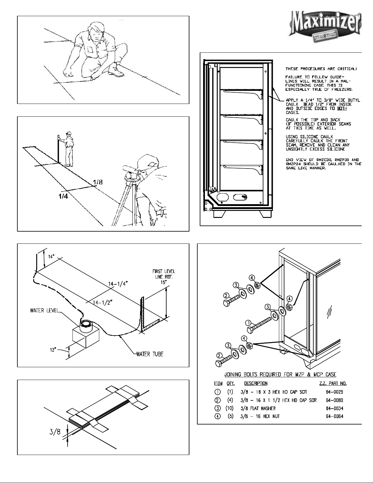
Leveling (See Figure 1)
Refrigeration equipment must be installed perfectly
level to allow efficient operation of the refrigeration
coils and complete drainage of defrost water. Since a
level area is seldom available, the following steps are
recommended to insure a level installation.
1. Measure off and mark on floor the exact dimensions of the case line-up. (Check blueprints).
2. Snap a chalk line at the locations for the front and
back positions of the base rails.
3. Mark locations of all joints (front and back).
4. Using a transit, find the highest point along both
base rail position lines. Using the high point as a
reference, mark the difference directly on the floor
to each joint (front and back).
5. If a transit is not available, a water level can be
used to mark reference elevation points. Water
levels can be purchased from a contractor supply
house for a minimal cost.
6. A string level can also be used to mark elevation
points. The string level should only be used on
short line-ups to avoid string sag.
These freezers must not be installed in the direct rays
of the sun or near a source of radiant heat.
Be certain that the floor under the installation is of
sufficient strength to prevent sagging. Out of level
conditions will result in reduced performance.
Wall cases, and back to back cases, should be positioned to allow a minimum 2 - 4 inch space behind the
back of a unit. This will allow necessary air to circulate
behind the unit.
7. Place the required number of shims (supplied) at
each joint (front and back) to equal the highest
point. Tape all shims in place.
8. Place additional support shims at the center of four
and five door cases base rails (front and back).
9. Use a carpenter’s level to check installation as you
go. The case should be level from front to back
and side to side. Install the case at the highest
point first, if part of a line-up.
RMZC30, RMZP30, RMZP24
Page 5
Shim joints to equal highest points
Measure and mark exact case outline
2
Mark floor level differences
Water level elevation points
Figure 2: Caulking cases to be joined
Figure 3: Joining 24” Door Reach-In Freezers
RMZC30, RMZP30, RMZP24
Page 6

Joining Freezers
These reach-In freezers have been engineered for
continuous display. This means that any number of
cases can be joined together to create a display of any
desired length. Reach-In freezers are built on permanent steel skids to promote easy installation. The
cases can be moved on pipe rollers or with a Johnson
Bar. The ends of the case are protected with a removable steel plate.
To install Reach-Ins, perform the following steps:
Install a tee to the outlet pipe and a PVC drain trap to
the tee. Plug the open end of the tee using the cleanout plug supplied with the drain trap kit. The drain line
must be pitched away from the case a minimum of 1/4
inch per foot. The tee, drain trap, and plug are supplied standard with the case.
Cart Bumper
The cart bumper should be installed at the bottom
front of the case. (See Figure 6) The assembly is
adjustable to compensate for uneven floors.
1. Set the first Reach-In into the desired position and
level it. Run a 3/8-inch diameter bead of Butyl
caulk 1/2 inch in from both the inner and outer
surfaces of the case end. (See Figure 2)
2. Push the second Reach-In against the end of the
first. Level the second Reach-In. Remove the left
and right end coil covers and the rectangular
pocket hole covers, accessing the holes in the end
panels of each freezer as shown. (See Figure 3 for
24” door cases and Figure 4 for 30“ door cases).
Install tee strips between the doorframes at case
joints on 30” door cases. ( See Figure 5) Use
the special screws and nuts provided.
3. Start the joining bolts, but do not tighten them.
Begin tightening the bolts at the top rear, working
down the back of the case and up the front making
sure that the front seams are flush.
Drain Line
The drain is located at the center of the freezer in the
floor pan. On all 30” door cases, the drain can be
reached by removing the center coil covers. A plastic
access cover can then be removed from the fan
housing. On all 24” door cases, a small center cover
can be removed to access the drain. The 1-inch PVC
drain outlet is located at the center front of the freezer
behind the kick plate.
Center and hook the bumper assembly on the hangers provided.
In continuous line-ups, place a kick plate joint strip at
each joint. On case ends, lineup an end kick plate
with the front mounting holes. Fasten the rear of the
end kick plate to the case using TECH screws.
Slide the front kick plate behind the bumper assembly
and in front of the end kick plate or kick plate joint strip.
Install three screws (two screws on 2-door only) to hold
the kick plate and bumper in place. The screws attach
the kickplate to a bracket with a timmerman.
A bumper joint strip can be installed over the bumper
at the joints. This is standard on Euro Style Trim and
optional on Classic Style Trim.
REFRIGERATION
General
Unless otherwise specified, the liquid and suction
connections are made inside the case under the
evaporator fan/coil cover. Refrigerant piping may
enter the case through the front left bottom. (See
Figure 10, 11, and 12) Alternate locations are out the left
rear bottom of case or left rear top of case. After
connections have been made, the refrigeration access
hole in the freezer must be sealed completely with
aerosol-dispensed Urethane insulation or equivalent
(ie: great stuff).
RMZC30, RMZP30, RMZP24
Page 7
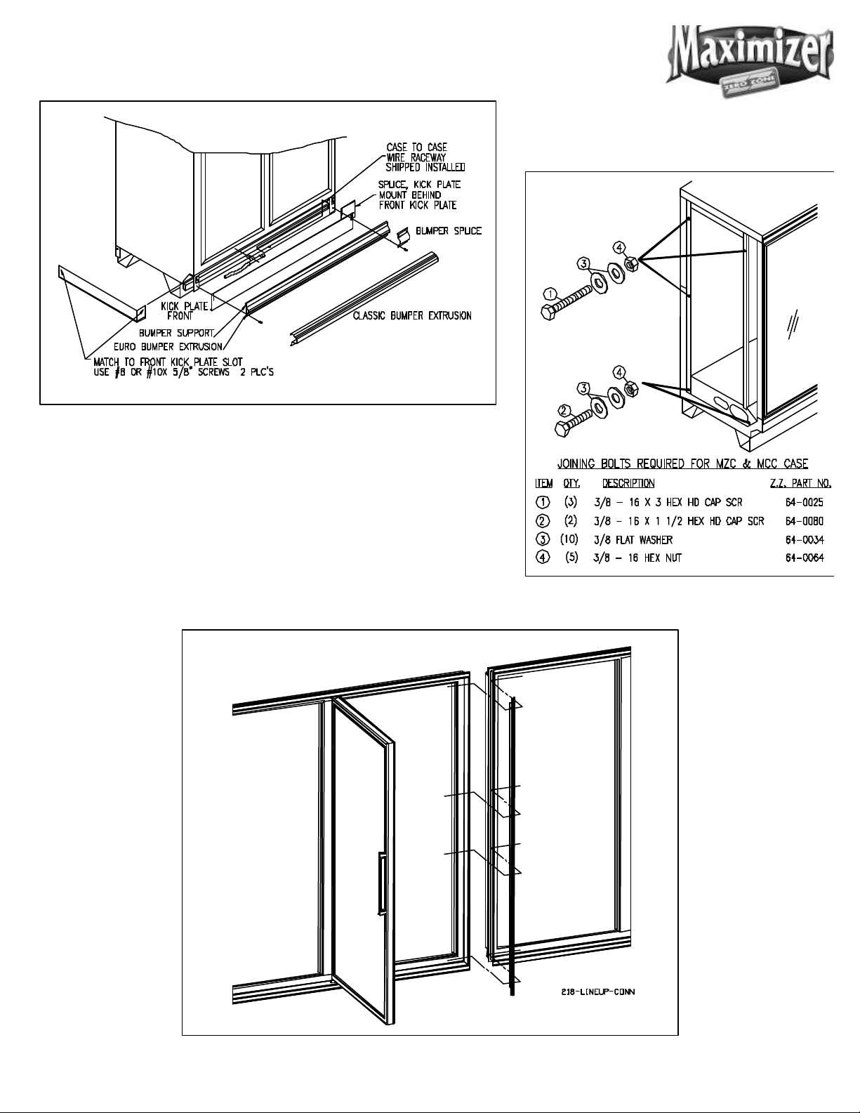
Figure 6: Installing The Cart Bumper
4
Figure 4: Joining 30” Door Reach-In Freezers
Figure 5: Installing Tee Strips
RMZC30, RMZP30, RMZP24
Page 8
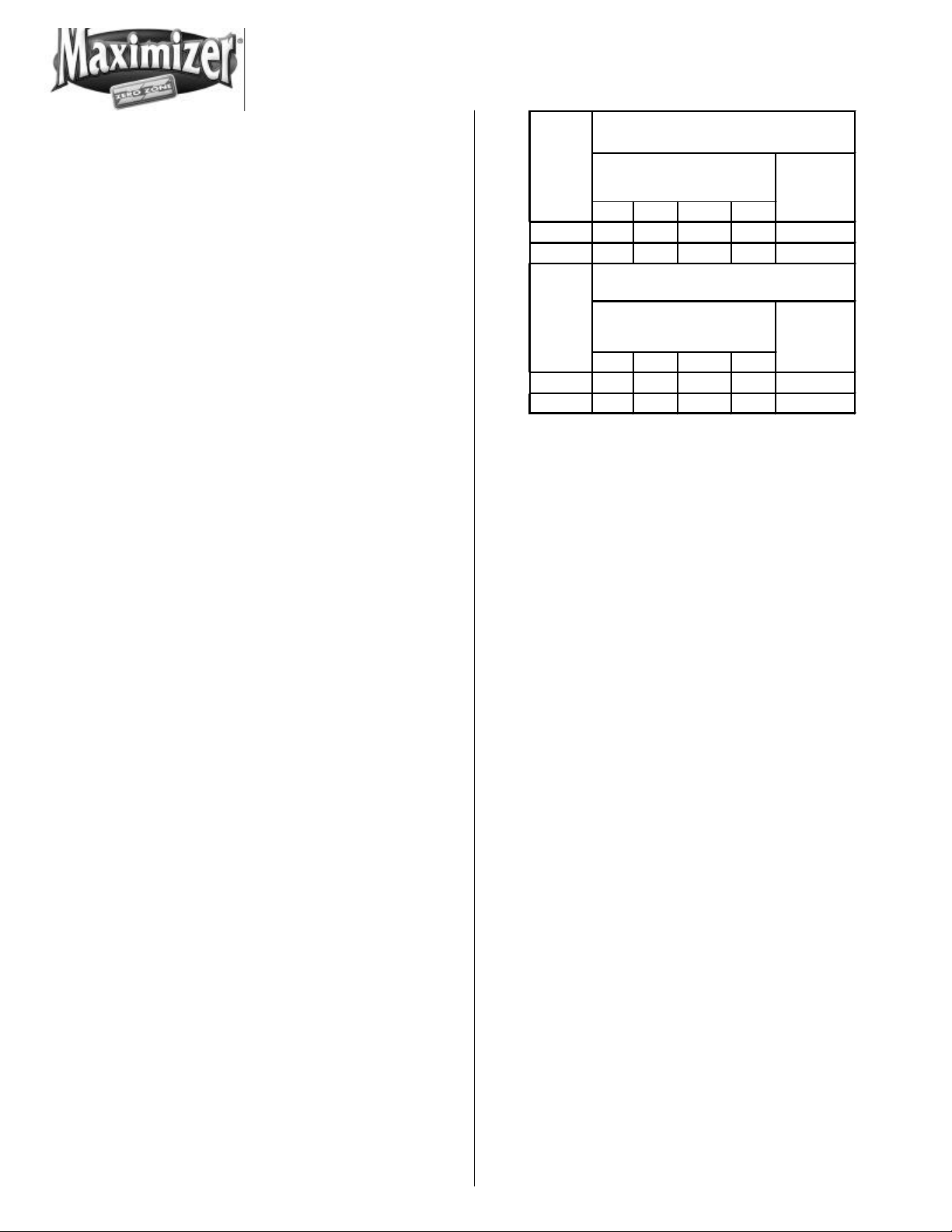
Refrigerant Piping
R-502
TEMP.
TEMP.
5
Frozen Food
Correct refrigeration line sizing and installation is
essential for proper system operation. The following
tables (Tables 1 through 8) list R502, R404A, R507, and
R-22 line sizes for different combinations of frozen
food and ice cream freezers. A P-trap must be installed at the bottom of all vertical suction risers.
When two or more freezer sections are connected to
one compressor, the main liquid and suction line for
the group should be run through the freezers and
brought out through the refrigeration outlet of one
freezer only. A piping chase allows the refrigerant
lines to be run out of the right or left end frame.
The compressor should be installed as close as possible to the freezers to reduce pressure drop. If the
compressor is located above the freezer, check the
refrigerant line size tables (Tables 1 through 8) in the
back of this manual to determine the riser line size.
Install a shallow trap at the bottom of the riser. Use a
flexible connection (vibration eliminator) between the
suction line and compressor.
The suction and liquid lines may be taped together to
form an external heat exchanger. Insulate the tubing
for at least 20 feet from the freezer outlet.
The best location for the liquid line drier is inside the
freezing compartment. However, it may be installed
near the compressor for easy maintenance. Install
moisture indicating sight glass at the outlet end of the
drier.
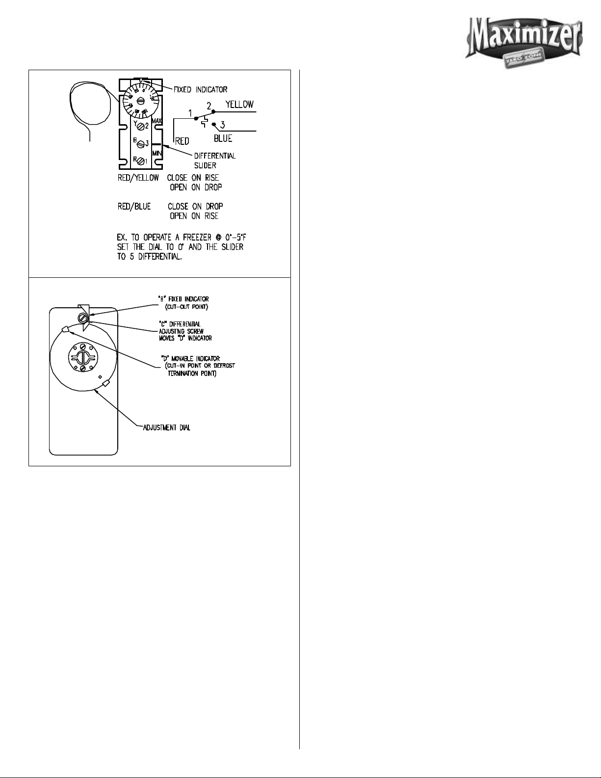
Temperature Control
A low pressure or temperature control can be used to
control freezer temperature. The control should be
selected with adequate contact capacity for the
switching load. In rack systems, an evaporator pressure-regulating valve may be used to control the
evaporating temperature.
The settings (See Figure 7) are approximate due to
variations in gauge accuracy, differences in compressor efficiency, line pressure drop and super
Pressure
(psig)
R-22 R502 R404A R507
Cut In 24 31 33 35 +2°F
Cut Out 14 19 21 22 -4° F
Ice Cream
Pressure
(psig)
R-22
Cut In 19 25 26 28 -5°F
Cut Out 9 14 15 17 -11°F
Figure 7: Temperature Control Settings
R404A R507
RETURN
AIR
RETURN
AIR
heat settings. Before making adjustments for store or
stocking conditions, make sure the super heat is set
between 6°F and 10°F.
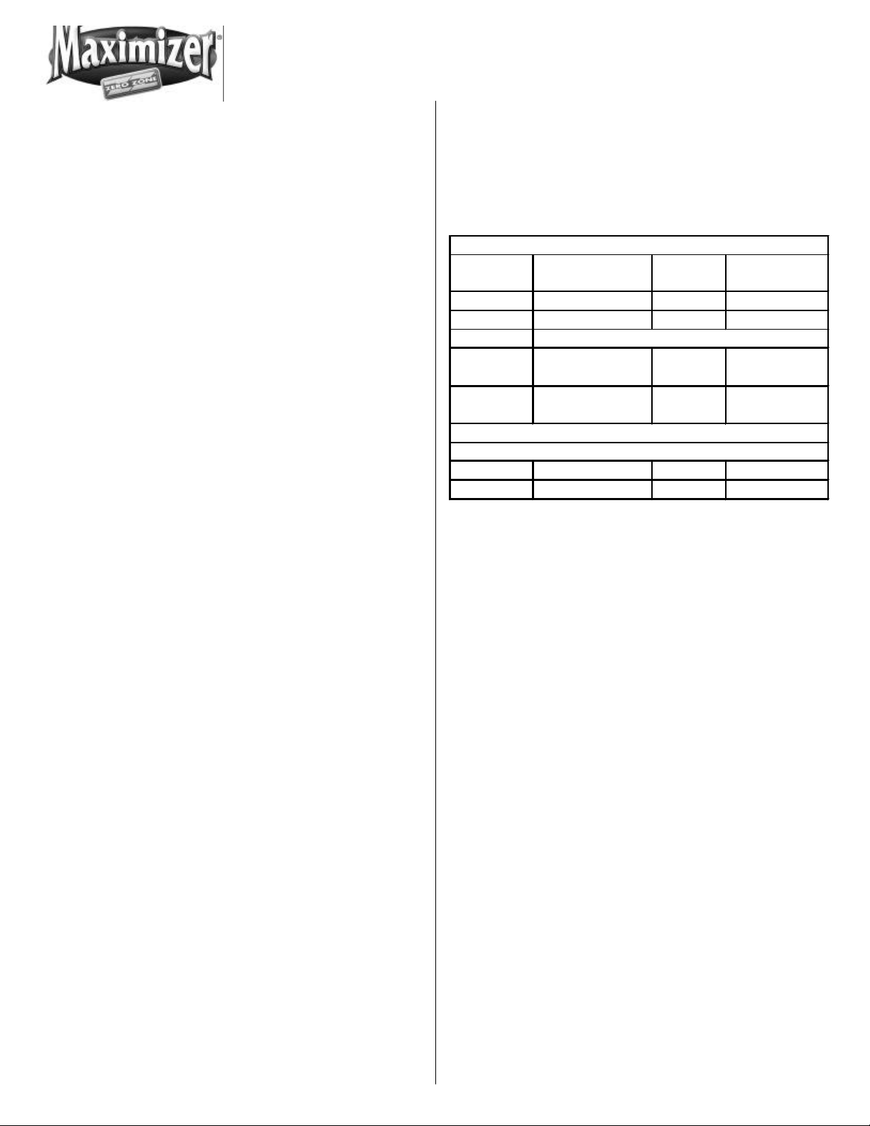
Temperature Control Adjustment
When factory installed, the temperature control is
located toward the right end of the freezer behind the
black kick plate. The sensing bulb is located under the
coil cover inside the cabinet. It should be wired in
series with the low-pressure (L.P.) control. The wiring
diagram (Figure 16) shows use of the thermostat in a
pump down system. (Figure 8) shows two types of
temperature controls.
Leak Check-Evacuation-Charging
After all of the refrigeration piping and system components have been assembled, the entire system must
be pressurized and checked for leaks. Use nitrogen
and refrigerant vapor to check for leaks. A Halide leak
detector or an electronic leak detector is recommended.
If the system is sealed, evacuate with a deep vacuum
pump. Triple evacuation to a minimum of 500 microns
and nitrogen sweep is recommended. After the
system has been thoroughly evacuated of all moisture
and non-condensable gas, charge the system with the
proper refrigerant, using “hi-side/low-side” charging
techniques.
RMZC30, RMZP30, RMZP24
Page 9
Figures 10, 11, and 12. All internal wiring has been
done at the factory. It has been terminated in the
electrical compartment located behind the kick rail at
the right end of the case. A terminal block has been
used to simplify field connections.
The line side of the contactor is energized with 115 volts
at all times. The 115-volt loads in the freezer are
energized at all times except during defrost and
during post-defrost pulldown. The 208/230 volt
defrost element is OFF at all times except during
defrost. The time clock is in operation at all times.
Note: All wiring must comply with the National Electrical Code and all local codes.
DEFROSTING
General
Figure 8: Typical Temperature Controls
Figure 14 shows the typical wiring diagram for a
freezer equipped with electric defrost. Figure 15 shows
the typical wiring diagram for a freezer equipped with
hot gas defrost. Each case is provided with a wiring
diagram located in the electric box that shows the
exact wiring of the case.
Figure 16 shows the typical wiring of one case with the
standard temperature terminating defrost control. The
defrost heaters will de-energize when the defrost
termination control has been satisfied.
Periodic defrosting to keep the coil free of frost is
accomplished automatically by a time clock used in
conjunction with an electric, hot gas, or reduced
temperature gas injection defrost system. The most
reliable and efficient defrost system for a single case
uses a time clock that incorporates a defrost termination device. Time clocks can be purchased that terminate on coil temperature or case coil pressure. These
clocks have the ability to match the defrost time to the
frost load on the coil. Coil temperature is sensed by
the defrost termination thermostat supplied as standard on all Zero Zone freezers. Pressure terminating
clocks generally have the pressure switch built into the
time clock. A time clock can be purchased from Zero
Zone or from a local refrigeration supply house.
There are many control options available for multiple
case defrost systems. Wiring diagrams and instructions can be obtained by calling Zero Zone’s Service
Department.
External wiring should be sized according to the
amperage rating stamped on the serial plate. The
RMZC30, RMZP30, RMZP24
Page 10
Electric Defrost
Saturated Suction Pressure Equal to 50 ° F.
Time (MIn.)
TIME ONLY TERMINATION
7
When the pin in the 24 hour dial reaches the TIME
arrow, the clock will trip and the defrost cycle will start.
At that time, the clock will stop the compressor, energize the 208/230 volt defrost heater, and energize the
normally closed 208/230 volt contactor. This deenergizes the 115-volt fans, lights, and anti-sweat
heaters.
After the defrost period, the compressor will operate.
When the coil temperature reaches +5°F, the fan, light
and anti-sweat heater limit thermostats will close,
starting the fans, lights and anti-sweat heaters.
Gas Defrost
Several types of gas defrost methods in conjunction
with time actuated, time or temperature terminated
defrost timers can be used to defrost the evaporator.
Liquid condensed in the serpentine passes through a
check valve into the liquid line. (See Figure 18 and 20)
Refer to the defrost frequency and termination recommendations that follow on Figure 9.
TEMPERATURE/PRESSURE TERMINATION
Reduced Temp.
Gas Defrost
Frequency
Temp.(°F)** 50 50 50
Pressure
Fail Safe
Time (Min.) 40 30 54
Drain
Time (Min.) 14-22 min. 12-20 min. 40-45 min.
Drain Time 0-3 0-3 0
1 1 1
0-3 0-3 0
Hot Gas Electric
The refrigeration system designer and installer are
responsible for correct line sizing for effective gas
defrost and liquid return from the freezers. Sizing and
component selection depend on the type of defrost,
size, and location of high side refrigeration system.
Zero Zone freezers equipped for gas defrost consist of
a side port, distributor and check valve for coil defrost,
and a check valve and serpentine coil attached to the
bottom of the pan to ensure pan and drain defrost.
Liquid and suction line connections are made inside
the case, through the refrigeration access hole located
in the floor pan on the left side of the freezer.
The timer starts the gas defrost cycle by energizing a
solenoid, reversing valve, or directional valve. The gas
is injected from the source into the suction line of the
evaporator to be defrosted. The gas flows into the
serpentine coil attached to the floor of the case and
into the evaporator. Condensed liquid leaves the
evaporator through the side port distributor, through a
check valve into the liquid line.
Figure 9: Defrost Frequency and Termination
Refrigeration technician should recheck coil condition after one
week of operation to be certain that the frequency and duration
of defrost is adequate for the particular store and locality. For
example, if defrost voltage is below 200 volts, additional failsafe time may be required.
Temp. termination thermostats should be wired in series for
multiple evaporator installations.
Limit Thermostat
Each freezer has factory set limit thermostats attached
to the return bends of the coil on the right end of the
freezer to regulate the operation of the evaporator
fans, freezer lights, and anti-sweat heaters.
OPERATION OF THE LIMIT THERMOSTATS CAUSES THE
EVAPORATOR FANS, FREEZER LIGHTS, AND ANTI-SWEAT
HEATERS TO REMAIN OFF UNTIL THE COMPRESSOR IS
OPERATING AND THE COIL TEMPERATURE IS BROUGHT
BELOW THE THERMOSTAT CUT-IN SETTING (+5°F ).
When the freezer first operates, the fans and lights
may cycle off and on a few times until coil temperature
is below +5 degrees F .
RMZC30, RMZP30, RMZP24
Page 11

USER INFORMATION
8
Light Switch
Cleaning
The freezer should be thoroughly cleaned before startup and routinely thereafter to maintain a clean appearance. Use mild detergent and warm water (never
an abrasive cleaner) to wipe out the inside of the
freezer. Wash down all glass doors with glass
cleaner. The freezer will remain bright and sparkling
with just a few minutes of cleaning each week. The
case drain should be regularly cleared of debris and
price tags.
Note: Do not use high-pressure water or steam to
clean the interior.
Shelf Location
The shelves are adjustable in 1-inch increments on
cantilever shelf cases and 1/2-inch increments on
pilaster cases and may be located in any position for
best display advantage.
Be sure shelf clips or brackets are completely
seated before installing the shelf.
Loading the Freezer
The freezer may be loaded with merchandise after it
has been operated for at least 24 hours with correct
case temperature and proper control operation. While
loading the shelves, leave at least 1 1/2 inch between
the top of the merchandise and the shelf above it so
the customer can remove the merchandise. The 1 1/2inch space allows an air curtain on the top of the
product.
The light switch is located on the mullion by the hinge
side right hand door. Turn the light switch off during
the initial freezer temperature pull-down to prevent the
freezer lights from cycling off and on. Always turn the
lights off when replacing lamps.
SERVICE
See Figures 17 and 18 for the typical component layout
of the 30” door case. See Figures 19 and 20 for the
typical component layout of the 24” door cases.
Cart Bumper
The cart bumper must be removed to gain access to
the drain clean out and electrical connection. Disassemble the bumper and black kick rail by removing
the 2 or 3 metal screws located in the kick rail. The
bumper assembly can be lifted up and removed from
the case. The kick plate can be removed, exposing
the electric tray cover and drain. (Figure 6 shows the
bumper assembly)
Evaporator
The evaporator coil, located at the rear bottom of the
freezer, is factory assembled with distributor, expansion valve, and heat exchanger. To inspect the 30”
door coil, remove the center or left of center coil cover.
A small inspection port is located at the rear of the
case. To inspect the entire 30” coil, remove the remaining coil covers and raise the evaporator cover.
The coil on the 24” door cases accessed by removing
the screws from the coil cover. Rotating it at the rear
integral hinge can raise the cover.
Expansion Valve
Unless otherwise specified, an externally equalized
thermostatic expansion valve with pressure limiting
charge adjustable super-heat and thermal bulb is
mounted to the evaporator coil. Adjust the super-
RMZC30, RMZP30, RMZP24
Page 12

heat setting for maximum coil effectiveness. Typical
9
super heat settings are between 6°F and 10°F. To
adjust the expansion valve, remove the right end coil
cover. Remove the cap from the bottom of the valve.
When looking at the valve stem end, turn the valve
stem counterclockwise to decrease super heat. Turn
the valve stem clockwise to increase super heat.
Measure the suction line temperature at the expansion valve sensing bulb and compare it to the suction
temperature corresponding to the saturated pressure.
Make sure that line pressure drop is taken into account.
metal clips holding the heater pan from both ends of
the coil end plates so they disengage the heater pan.
Then slide out the complete heater pan assembly from
under the coil and under the fan housing. Slowly lift
the heater pan assembly between coil and fan housing, turning it on edge while lifting.
Evaporator Fans
Air is circulated throughout the freezer with 115-volt low
temperature fan motors. These motors must be
operating at all times except during defrost.
Turn the valve stem only 1/4 turn at a time and allow
sufficient time (20 to 30 minutes) for the valve to settle
before making any further adjustments. Replace the
valve stem cap after the valve super-heat has been
adjusted. BE CERTAIN THE VALVE STEM CAP IS WIPED
DRY FIRST.
! CAUTION !
DISCONNECT POWER TO THE CASE BEFORE
SERVICING ELECTRICAL COMPONENTS
Defrost Heater Element
The heater element is located under the coil. The
electric wire leads are connected in the junction box
behind the front kick rail.
30” Door Heater Element Removal
30” Door Fan Removal
Turn off power to fans.
Remove coil cover.
Unplug fan from fan power supply plug located on the
front face of the fan housing.
Remove the two mounting bolts and remove the fan
assembly from the fan housing.
24” Door Fan Removal
Turn off power to fans.
Remove wire fan guard.
Remove fan motor mounting bracket screws.
Set motor fan assembly on floor of case.
To remove the defrost element, remove the coil covers.
Lift the inner coil cover upward and tip the fan housing
forward. This will expose the coil. Remove both fan
housing end brackets and center coil supports, then
slide out the complete heater pan assembly from
under the coil. Slowly lift the heater pan assembly
between the coil and fan housing, turning it on edge
while lifting.
24” Door Heater Element Removal
To remove the defrost element, remove the right, left,
and center coil covers. Next, remove the fan housing
legs and air baffle assembly fastened to the rear edge
of the fan housing with sheet metal screws. Turn the
Unplug power supply plug from fan.
Lift and rotate motor fan assembly from case.
Lights
High output 1500 milliamp T-10 lamps are standard
with 24” door and MZP freezers. These lamps are
optional on MZC freezers. To ensure maximum component life, always replace with 1500 milliamp lamps.
Use retainer clips and lamp shields.
RMZC30, RMZP30, RMZP24
Page 13

To change a lamp, turn off the light switch and remove
10
the retainer clip located between the top socket and
end cap. Carefully push the lamp up into the springloaded lamp socket to allow the lamp to be removed
from the bottom socket. (See Figure 10.) Remove the
end caps and shield. All
T-10 lamps must use end caps and shields.
must be installed over the lamp. Anthony’s lamp is
removed by sliding the end caps off of the lamp.
Detailed information is contained in the door instruction booklet.
Figure 10: Socket Detail
Ballasts
Zero Zone freezer ballasts are located either behind
the kick plate or in the door mullions.
Alternate Lighting -T8
T-8 lighting is standard on the 30” door case and
optional on the 24” door freezers. Many door manufacturers provide premium lighting systems. These
systems use a lens to direct light output evenly across
the shelves. The lens must be removed to access the
lamp. Ardco’s lamp may be removed by turning it 90
degrees and sliding the lamp pins out of the lamp
socket slot. The jacket
RMZC30, RMZP30, RMZP24
Page 14

EVAPORATOR FOR FROZEN FOOD
REMOTE REACH-IN FREEZER W/ 30" X 63" DOORS
BTU/HR
Table 1
11
MODEL RMZC30 & RMZP30
REFRIGERANT R-502, R-404a, R-507 @ -11° F
NO.
OF
DOOR
S
2 (1) 2-DR 5'-7 1/16" 3,141 3/8 3/8 3/8 5/8 5/8 7/8
3 (1) 3-DR 8'-1 1/2" 4,544 3/8 3/8 3/8 5/8 7/8 7/8
4 (1) 4-DR 10'-7 15/16" 5,892 3/8 3/8 3/8 7/8 7/8 7/8
5 (1) 5-DR 13'-2 3/8" 7,340 3/8 3/8 3/8 7/8 7/8 1 1/8
6 (2) 3-DR 15'-10" 8,808 3/8 3/8 3/8 7/8 7/8 1 1/8
7 (1) 3-DR & (1) 4-DR 18'-4 7/16" 10,276 3/8 3/8 3/8 7/8 1 1/8 1 1/8
8 (2) 4-DR 20'-10 7/8" 11,744 3/8 3/8 1/2 7/8 1 1/8 1 1/8
9 (1) 4-DR & (1) 5-DR 23'-5 5/16" 13,212 3/8 3/8 1/2 7/8 1 1/8 1 1/8
10 (2) 5-DR 25'-11 3/4" 14,680 3/8 1/2 1/2 1 1/8 1 1/8 1 1/8
11 (1) 3-DR & (2) 4-DR 28'-7 3/8" 16,148 3/8 1/2 1/2 1 1/8 1 1/8 1 3/8
12 (3) 4-DR 31'-1 13/16" 17,616 3/8 1/2 1/2 1 1/8 1 1/8 1 3/8
13 (2) 4-DR & (1) 5-DR 33'-8 1/4" 19,084 3/8 1/2 1/2 1 1/8 1 1/8 1 3/8
14 (1) 4-DR & (2) 5-DR 36'-2 11/16" 20,552 1/2 1/2 1/2 1 1/8 1 3/8 1 3/8
15 (3) 5-DR 38'-9 1/8" 22,020 1/2 1/2 5/8 1 1/8 1 3/8 1 3/8
16 (4) 4-DR 41'-4 3/4" 23,488 1/2 1/2 5/8 1 1/8 1 3/8 1 3/8
17 (3) 4-DR & (1) 5-DR 43'-11 3/16" 24,956 1/2 1/2 5/8 1 1/8 1 3/8 1 3/8
18 (2) 4-DR & (2) 5-DR 46'-5 5/8" 26,424 1/2 5/8 5/8 1 1/8 1 3/8 1 3/8
19 (1) 4-DR & (3) 5-DR 49'-1 1/16" 27,892 1/2 5/8 5/8 1 1/8 1 3/8 1 5/8
20 (4) 5-DR 51'-6 1/2" 29,360 1/2 5/8 5/8 1 3/8 1 3/8 1 5/8
21 (4) 4-DR & (1) 5-DR 54'-2 1/8" 30,828 1/2 5/8 5/8 1 3/8 1 3/8 1 5/8
22 (3) 4-DR & (2) 5-DR 56'-8 9/16" 32,296 1/2 5/8 5/8 1 3/8 1 3/8 1 5/8
23 (2) 4-DR & (3) 5-DR 59'-3" 33,764 1/2 5/8 5/8 1 3/8 1 3/8 1 5/8
24 (1) 4-DR & (4) 5-DR 61'-9 7/16" 35,232 1/2 5/8 5/8 1 3/8 1 5/8 1 5/8
25 (5) 5-DR 64'-3 7/8" 36,700 1/2 5/8 5/8 1 3/8 1 5/8 1 5/8
26 (4) 4-DR & (2) 5-DR 66'-11 1/2" 38,168 1/2 5/8 5/8 1 3/8 1 5/8 1 5/8
27 (3) 4-DR & (3) 5-DR 69'-5 15/16" 39,636 5/8 5/8 7/8 1 3/8 1 5/8 1 5/8
28 (2) 4-DR & (4) 5-DR 72'-3/8" 41,104 5/8 5/8 7/8 1 3/8 1 5/8 1 5/8
29 (1) 4-DR & (5) 5-DR 74'-6 13/16" 42,572 5/8 5/8 7/8 1 3/8 1 5/8 1 5/8
30 (6) 5-DR 77'-1 1/4" 44,040 5/8 7/8 7/8 1 3/8 1 5/8 2 1/8
FREEZER
COMBINATIONS
TOTAL
LENGTH
W/ENDS
RECOMMENDED
LIQUID LINE SIZES
EQUIVALENT LENGTH, FEET
50 100 150 50 100 150
RECOMMENDED
SUCTION LINE SIZES
EQUIVALENT LENGTH, FEET
NOTE: BTU RATINGS FOR T-8 ELECTRONIC LIGHTING SYSTEM. ADD 30 BTU/DOOR FOR T-10
LIGHTING. DEDUCT 57 BTU/HR PER DOOR FOR PSC FANS. CASES DESIGNED TO OPERATE IN AN
AMBIENT OF 75°F OR LOWER AND RELATIVE HUMIDITY OF 55% OR LOWER. SHADED CELL
INDICATES VERTI
AL SUCTION RISERS NEED TO BE ONE SIZE SMALLER THAN SIZE SHOWN
RMZC30, RMZP30, RMZP24
RMZC30, RMZP30, RMZP24
Page 15

REMOTE REACH-IN FREEZER W/ 30" X 63" DOORS
NO. OF
BTU/HR
Table 2
12
MODEL RMZC30 & RMZP30
REFRIGERANT R-502, R-404a, R-507 @ -18° F
EVAPORATOR FOR ICE CREAM
DOOR
S
2 (1) 2-DR 5'-7 1/16" 3,393 3/8 3/8 3/8 5/8 7/8 7/8
3 (1) 3-DR 8'-1 1/2" 4,922 3/8 3/8 3/8 7/8 7/8 7/8
4 (1) 4-DR 10'-7 15/16" 6,396 3/8 3/8 3/8 7/8 7/8 7/8
5 (1) 5-DR 13'-2 3/8" 7,970 3/8 3/8 3/8 7/8 7/8 1 1/8
6 (2) 3-DR 15'-10" 9,564 3/8 3/8 3/8 7/8 1 1/8 1 1/8
7 (1) 3-DR & (1) 4-DR 18'-4 7/16" 11,158 3/8 3/8 1/2 7/8 1 1/8 1 1/8
8 (2) 4-DR 20'-10 7/8" 12,752 3/8 3/8 1/2 1 1/8 1 1/8 1 1/8
9 (1) 4-DR & (1) 5-DR 23'-5 5/16" 14,346 3/8 1/2 1/2 1 1/8 1 1/8 1 3/8
10 (2) 5-DR 25'-11 3/4" 15,940 3/8 1/2 1/2 1 1/8 1 1/8 1 3/8
11 (1) 3-DR & (2) 4-DR 28'-7 3/8" 17,534 3/8 1/2 1/2 1 1/8 1 3/8 1 3/8
12 (3) 4-DR 31'-1 13/16" 19,128 3/8 1/2 1/2 1 1/8 1 3/8 1 3/8
13 (2) 4-DR & (1) 5-DR 33'-8 1/4" 20,722 1/2 1/2 1/2 1 1/8 1 3/8 1 3/8
14 (1) 4-DR & (2) 5-DR 36'-2 11/16" 22,316 1/2 1/2 5/8 1 1/8 1 3/8 1 3/8
15 (3) 5-DR 38'-9 1/8" 23,910 1/2 1/2 5/8 1 3/8 1 3/8 1 5/8
16 (4) 4-DR 41'-4 3/4" 25,504 1/2 1/2 5/8 1 3/8 1 3/8 1 5/8
17 (3) 4-DR & (1) 5-DR 43'-11 3/16" 27,098 1/2 5/8 5/8 1 3/8 1 3/8 1 5/8
18 (2) 4-DR & (2) 5-DR 46'-5 5/8" 28,692 1/2 5/8 5/8 1 3/8 1 3/8 1 5/8
19 (1) 4-DR & (3) 5-DR 49'-1 1/16" 30,286 1/2 5/8 5/8 1 3/8 1 5/8 1 5/8
20 (4) 5-DR 51'-6 1/2" 31,880 1/2 5/8 5/8 1 3/8 1 5/8 1 5/8
21 (4) 4-DR & (1) 5-DR 54'-2 1/8" 33,474 1/2 5/8 5/8 1 3/8 1 5/8 1 5/8
22 (3) 4-DR & (2) 5-DR 56'-8 9/16" 35,068 1/2 5/8 5/8 1 3/8 1 5/8 1 5/8
23 (2) 4-DR & (3) 5-DR 59'-3" 36,662 1/2 5/8 5/8 1 3/8 1 5/8 1 5/8
24 (1) 4-DR & (4) 5-DR 61'-9 7/16" 38,256 1/2 5/8 5/8 1 3/8 1 5/8 2 1/8
25 (5) 5-DR 64'-3 7/8" 39,850 5/8 5/8 7/8 1 3/8 1 5/8 2 1/8
26 (4) 4-DR & (2) 5-DR 66'-11 1/2" 41,444 5/8 5/8 7/8 1 3/8 1 5/8 2 1/8
27 (3) 4-DR & (3) 5-DR 69'-5 15/16" 43,038 5/8 5/8 7/8 1 5/8 1 5/8 2 1/8
28 (2) 4-DR & (4) 5-DR 72'-3/8" 44,632 5/8 5/8 7/8 1 5/8 1 5/8 2 1/8
29 (1) 4-DR & (5) 5-DR 74'-6 13/16" 46,226 5/8 5/8 7/8 1 5/8 2 1/8 2 1/8
30 (6) 5-DR 77'-1 1/4" 47,820 5/8 5/8 7/8 1 5/8 2 1/8 2 1/8
FREEZER
COMBINATIONS
TOTAL
LENGTH
W/ENDS
RECOMMENDED
LIQUID LINE SIZES
EQUIVALENT LENGTH, FEET
50 100 150 50 100 150
RECOMMENDED
SUCTION LINE SIZES
EQUIVALENT LENGTH, FEET
NOTE: BTU RATINGS FOR T-8 ELECTRONIC LIGHTING SYSTEM. ADD 30 BTU/DOOR FOR T-10
LIGHTING. DEDUCT 57 BTU/HR PER DOOR FOR PSC FANS. CASES DESIGNED TO OPERATE IN AN
AMBIENT OF 75°F OR LOWER AND RELATIVE HUMIDITY OF 55% OR LOWER. SHADED CELL
INDICATES VERTIC
AL SUCTION RISERS NEED TO BE ONE SIZE SMALLER THAN SIZE SHOWN
RMZC30, RMZP30, RMZP24
Page 16

INDICATES VERTIC
EVAPORATOR FOR FROZEN FOOD
BTU/HR
Table 3
13
REMOTE REACH-IN FREEZER W/ 30" X 63" DOORS
MODEL RMZC30 & RMZP30
REFRIGERANT R-22 @ -11° F
NO.
OF
DOOR
S
2 (1) 2-DR 5'-7 1/16" 3,141 3/8 3/8 3/8 5/8 5/8 5/8
3 (1) 3-DR 8'-1 1/2" 4,544 3/8 3/8 3/8 5/8 7/8 7/8
4 (1) 4-DR 10'-7 15/16" 5,892 3/8 3/8 3/8 5/8 7/8 7/8
5 (1) 5-DR 13'-2 3/8" 7,340 3/8 3/8 3/8 7/8 7/8 7/8
6 (2) 3-DR 15'-10" 8,808 3/8 3/8 3/8 7/8 7/8 7/8
7 (1) 3-DR & (1) 4-DR 18'-4 7/16" 10,276 3/8 3/8 3/8 7/8 7/8 1 1/8
8 (2) 4-DR 20'-10 7/8" 11,744 3/8 3/8 3/8 7/8 1 1/8 1 1/8
9 (1) 4-DR & (1) 5-DR 23'-5 5/16" 13,212 3/8 3/8 3/8 7/8 1 1/8 1 1/8
10 (2) 5-DR 25'-11 3/4" 14,680 3/8 3/8 3/8 7/8 1 1/8 1 1/8
11 (1) 3-DR & (2) 4-DR 28'-7 3/8" 16,148 3/8 3/8 3/8 7/8 1 1/8 1 1/8
12 (3) 4-DR 31'-1 13/16" 17,616 3/8 3/8 1/2 1 1/8 1 1/8 1 1/8
13 (2) 4-DR & (1) 5-DR 33'-8 1/4" 19,084 3/8 3/8 1/2 1 1/8 1 1/8 1 3/8
14 (1) 4-DR & (2) 5-DR 36'-2 11/16" 20,552 3/8 3/8 1/2 1 1/8 1 1/8 1 3/8
15 (3) 5-DR 38'-9 1/8" 22,020 3/8 1/2 1/2 1 1/8 1 1/8 1 3/8
16 (4) 4-DR 41'-4 3/4" 23,488 3/8 1/2 1/2 1 1/8 1 3/8 1 3/8
17 (3) 4-DR & (1) 5-DR 43'-11 3/16" 24,956 3/8 1/2 1/2 1 1/8 1 3/8 1 3/8
18 (2) 4-DR & (2) 5-DR 46'-5 5/8" 26,424 3/8 1/2 1/2 1 1/8 1 3/8 1 3/8
19 (1) 4-DR & (3) 5-DR 49'-1 1/16" 27,892 3/8 1/2 1/2 1 1/8 1 3/8 1 3/8
20 (4) 5-DR 51'-6 1/2" 29,360 3/8 1/2 1/2 1 1/8 1 3/8 1 3/8
21 (4) 4-DR & (1) 5-DR 54'-2 1/8" 30,828 1/2 1/2 1/2 1 1/8 1 3/8 1 3/8
22 (3) 4-DR & (2) 5-DR 56'-8 9/16" 32,296 1/2 1/2 5/8 1 1/8 1 3/8 1 3/8
23 (2) 4-DR & (3) 5-DR 59'-3" 33,764 1/2 1/2 5/8 1 1/8 1 3/8 1 5/8
24 (1) 4-DR & (4) 5-DR 61'-9 7/16" 35,232 1/2 1/2 5/8 1 3/8 1 3/8 1 5/8
25 (5) 5-DR 64'-3 7/8" 36,700 1/2 1/2 5/8 1 3/8 1 3/8 1 5/8
26 (4) 4-DR & (2) 5-DR 66'-11 1/2" 38,168 1/2 1/2 5/8 1 3/8 1 3/8 1 5/8
27 (3) 4-DR & (3) 5-DR 69'-5 15/16" 39,636 1/2 5/8 5/8 1 3/8 1 3/8 1 5/8
28 (2) 4-DR & (4) 5-DR 72'-3/8" 41,104 1/2 5/8 5/8 1 3/8 1 3/8 1 5/8
29 (1) 4-DR & (5) 5-DR 74'-6 13/16" 42,572 1/2 5/8 5/8 1 3/8 1 5/8 1 5/8
30 (6) 5-DR 77'-1 1/4" 44,040 1/2 5/8 5/8 1 3/8 1 5/8 1 5/8
FREEZER
COMBINATIONS
TOTAL
LENGTH
W/ENDS
RECOMMENDED
LIQUID LINE SIZES
EQUIVALENT LENGTH, FEET
50 100 150 50 100 150
RECOMMENDED
SUCTION LINE SIZES
EQUIVALENT LENGTH, FEET
NOTE: BTU RATINGS FOR T-8 ELECTRONIC LIGHTING SYSTEM. ADD 30 BTU/DOOR FOR T-10
LIGHTING. DEDUCT 57 BTU/HR PER DOOR FOR PSC FANS. CASES DESIGNED TO OPERATE IN AN
AMBIENT OF 75°F OR LOWER AND RELATIVE HUMIDITY OF 55% OR LOWER. SHADED CELL
AL SUCTION RISERS NEED TO BE ONE SIZE SMALLER THAN SIZE SHOWN
RMZC30, RMZP30, RMZP24
Page 17

NO. OF
EVAPORATOR FOR ICE CREAM
BTU/HR
Table 4
14
REMOTE REACH-IN FREEZER W/ 30" X 63" DOORS
MODEL RMZC30 & RMZP30
REFRIGERANT R-22 @ -18° F
FREEZER
DOORS
10 (2) 5-DR 25'-11 3/4" 15,940 3/8 3/8 3/8 1 1/8 1 1/8 1 3/8
11 (1) 3-DR & (2) 4-DR 28'-7 3/8" 17,534 3/8 3/8 1/2 1 1/8 1 1/8 1 3/8
12 (3) 4-DR 31'-1 13/16" 19,128 3/8 3/8 1/2 1 1/8 1 1/8 1 3/8
13 (2) 4-DR & (1) 5-DR 33'-8 1/4" 20,722 3/8 3/8 1/2 1 1/8 1 3/8 1 3/8
14 (1) 4-DR & (2) 5-DR 36'-2 11/16" 22,316 3/8 1/2 1/2 1 1/8 1 3/8 1 3/8
15 (3) 5-DR 38'-9 1/8" 23,910 3/8 1/2 1/2 1 1/8 1 3/8 1 3/8
16 (4) 4-DR 41'-4 3/4" 25,504 3/8 1/2 1/2 1 1/8 1 3/8 1 3/8
17 (3) 4-DR & (1) 5-DR 43'-11 3/16" 27,098 3/8 1/2 1/2 1 1/8 1 3/8 1 3/8
18 (2) 4-DR & (2) 5-DR 46'-5 5/8" 28,692 3/8 1/2 1/2 1 1/8 1 3/8 1 5/8
19 (1) 4-DR & (3) 5-DR 49'-1 1/16" 30,286 3/8 1/2 1/2 1 3/8 1 3/8 1 5/8
20 (4) 5-DR 51'-6 1/2" 31,880 1/2 1/2 5/8 1 3/8 1 3/8 1 5/8
21 (4) 4-DR & (1) 5-DR 54'-2 1/8" 33,474 1/2 1/2 5/8 1 3/8 1 3/8 1 5/8
22 (3) 4-DR & (2) 5-DR 56'-8 9/16" 35,068 1/2 1/2 5/8 1 3/8 1 3/8 1 5/8
23 (2) 4-DR & (3) 5-DR 59'-3" 36,662 1/2 1/2 5/8 1 3/8 1 5/8 1 5/8
24 (1) 4-DR & (4) 5-DR 61'-9 7/16" 38,256 1/2 1/2 5/8 1 3/8 1 5/8 1 5/8
25 (5) 5-DR 64'-3 7/8" 39,850 1/2 5/8 5/8 1 3/8 1 5/8 1 5/8
26 (4) 4-DR & (2) 5-DR 66'-11 1/2" 41,444 1/2 5/8 5/8 1 3/8 1 5/8 1 5/8
27 (3) 4-DR & (3) 5-DR 69'-5 15/16" 43,038 1/2 5/8 5/8 1 3/8 1 5/8 1 5/8
28 (2) 4-DR & (4) 5-DR 72'-3/8" 44,632 1/2 5/8 5/8 1 3/8 1 5/8 2 1/8
29 (1) 4-DR & (5) 5-DR 74'-6 13/16" 46,226 1/2 5/8 5/8 1 3/8 1 5/8 2 1/8
30 (6) 5-DR 77'-1 1/4" 47,820 1/2 5/8 5/8 1 3/8 1 5/8 2 1/8
COMBINATIONS
2 (1) 2-DR 5'-7 1/16" 3,393 3/8 3/8 3/8 5/8 5/8 7/8
3 (1) 3-DR 8'-1 1/2" 4,922 3/8 3/8 3/8 5/8 7/8 7/8
4 (1) 4-DR 10'-7 15/16" 6,396 3/8 3/8 3/8 7/8 7/8 7/8
5 (1) 5-DR 13'-2 3/8" 7,970 3/8 3/8 3/8 7/8 7/8 1 1/8
6 (2) 3-DR 15'-10" 9,564 3/8 3/8 3/8 7/8 7/8 1 1/8
7 (1) 3-DR & (1) 4-DR 18'-4 7/16" 11,158 3/8 3/8 3/8 7/8 1 1/8 1 1/8
8 (2) 4-DR 20'-10 7/8" 12,752 3/8 3/8 3/8 7/8 1 1/8 1 1/8
9 (1) 4-DR & (1) 5-DR 23'-5 5/16" 14,346 3/8 3/8 3/8 7/8 1 1/8 1 1/8
TOTAL
LENGTH
W/ENDS
RECOMMENDED
LIQUID LINE SIZES
EQUIVALENT LENGTH, FEET
50 100 150 50 100 150
RECOMMENDED
SUCTION LINE SIZES
EQUIVALENT LENGTH, FEET
NOTE: BTU RATINGS FOR T-8 ELECTRONIC LIGHTING SYSTEM. ADD 30 BTU/DOOR FOR T-10
LIGHTING. DEDUCT 57 BTU/HR PER DOOR FOR PSC FANS. CASES DESIGNED TO OPERATE IN AN
AMBIENT OF 75°F OR LOWER AND RELATIVE HUMIDITY OF 55% OR LOWER. SHADED CELL
INDICATES VERTIC
AL SUCTION RISERS NEED TO BE ONE SIZE SMALLER THAN SIZE SHOWN
RMZC30, RMZP30, RMZP24
Page 18

INDICATES VERTIC
EVAPORATOR FOR FROZEN FOOD
NO. OF
BTU/HR
Table 5
15
REMOTE REACH-IN FREEZER W/ 24" X 63" DOORS
MODEL RMZP24
REFRIGERANT R-502, R-404a, R-507 @ -14° F
FREEZER
DOORS
10 (2) 5-DR 20'-11 1/4" 13,250 3/8 1/2 1/2 7/8 1.1/8 1.1/8
11 (1) 3-DR & (2) 4-DR 22'-10 3/8" 14,575 3/8 1/2 1/2 7/8 1.1/8 1.1/8
12 (3) 4-DR 25'-3 1/4" 15,900 3/8 1/2 1/2 1.1/8 1.1/8 1.1/8
13 (2) 4-DR & (1) 5-DR 27'-2 7/8" 17,225 1/2 1/2 1/2 1.1/8 1.1/8 1.3/8
14 (1) 4-DR & (2) 5-DR 29'-2 5/8" 18,550 1/2 1/2 1/2 1.1/8 1.1/8 1.3/8
15 (3) 5-DR 31'-2 3/8" 19,875 1/2 1/2 1/2 1.1/8 1.1/8 1.3/8
16 (4) 4-DR 33'-6 1/2" 21,200 1/2 1/2 1/2 1.1/8 1.3/8 1.3/8
17 (3) 4-DR & (1) 5-DR 35'-6 1/4" 22,525 1/2 1/2 1/2 1.1/8 1.3/8 1.3/8
18 (2) 4-DR & (2) 5-DR 37'-6" 23,850 1/2 1/2 5/8 1.1/8 1.3/8 1.3/8
19 (1) 4-DR & (3) 5-DR 39'-5 3/4" 25,175 1/2 1/2 5/8 1.1/8 1.3/8 1.3/8
20 (4) 5-DR 41'-1/2" 26,500 1/2 1/2 5/8 1.1/8 1.3/8 1.3/8
21 (4) 4-DR & (1) 5-DR 43'-9 5/8" 27,825 1/2 1/2 5/8 1.1/8 1.3/8 1.3/8
22 (3) 4-DR & (2) 5-DR 45'-9 3/8" 29,150 1/2 5/8 5/8 1.3/8 1.3/8 1.5/8
23 (2) 4-DR & (3) 5-DR 47'-9 1/8" 30,475 1/2 5/8 5/8 1.3/8 1.3/8 1.5/8
24 (1) 4-DR & (4) 5-DR 49'-8 7/8" 31,800 1/2 5/8 5/8 1.3/8 1.3/8 1.5/8
25 (5) 5-DR 51'-8 5/8" 33,125 1/2 5/8 5/8 1.3/8 1.3/8 1.5/8
26 (4) 4-DR & (2) 5-DR 54'-3/4" 34,450 1/2 5/8 5/8 1.3/8 1.3/8 1.5/8
27 (3) 4-DR & (3) 5-DR 56'-1/2" 35,775 1/2 5/8 5/8 1.3/8 1.5/8 1.5/8
28 (2) 4-DR & (4) 5-DR 58'-1/4" 37,100 1/2 5/8 5/8 1.3/8 1.5/8 1.5/8
29 (1) 4-DR & (5) 5-DR 60'-0" 38,425 1/2 5/8 5/8 1.3/8 1.5/8 1.5/8
30 (6) 5-DR 61'-11 3/4" 39,750 1/2 5/8 5/8 1.3/8 1.5/8 1.5/8
COMBINATIONS
2 (1) 2-DR 4'-8 7/8" 3,375 3/8 3/8 3/8 5/8 5/8 7/8
3 (1) 3-DR 6'-8 5/8" 4,455 3/8 3/8 3/8 5/8 7/8 7/8
4 (1) 4-DR 8'-8 3/8" 5,530 3/8 3/8 3/8 7/8 7/8 7/8
5 (1) 5-DR 10'-8 1/8" 6,625 3/8 3/8 3/8 7/8 7/8 7/8
6 (2) 3-DR 13'-1/4" 7,950 3/8 3/8 3/8 7/8 7/8 7/8
7 (1) 3-DR & (1) 4-DR 15'-0" 9,275 3/8 3/8 3/8 7/8 7/8 1.1/8
8 (2) 4-DR 16'-11 3/4" 10,600 3/8 1/2 1/2 7/8 1.1/8 1.1/8
9 (1) 4-DR & (1) 5-DR 18'-11 1/2" 11,925 3/8 1/2 1/2 7/8 1.1/8 1.1/8
TOTAL
LENGTH
W/ENDS
RECOMMENDED
LIQUID LINE SIZES
EQUIVALENT LENGTH, FEET
50 100 150 50 100 150
RECOMMENDED
SUCTION LINE SIZES
EQUIVALENT LENGTH, FEET
NOTE: BTU RATINGS FOR T-8 ELECTRONIC LIGHTING SYSTEM. ADD 30 BTU/DOOR FOR T-10
LIGHTING. DEDUCT 57 BTU/HR PER DOOR FOR PSC FANS. CASES DESIGNED TO OPERATE IN AN
AMBIENT OF 75°F OR LOWER AND RELATIVE HUMIDITY OF 55% OR LOWER. SHADED CELL
AL SUCTION RISERS NEED TO BE ONE SIZE SMALLER THAN SIZE SHOWN
RMZC30, RMZP30, RMZP24
Page 19

INDICATES VERTIC
REMOTE REACH-IN FREEZER W/ 24" X 63" DOORS
EVAPORATOR FOR ICE CREAM
NO. OF
BTU/HR
Table 6
16
MODEL RMZP24
REFRIGERANT R-502, R-404a, R-507 @ -20° F
FREEZER
DOORS
COMBINATIONS
2 (1) 2-DR 4'-8 7/8" 3,620 3/8 3/8 3/8 5/8 7/8 7/8
3 (1) 3-DR 6'-8 5/8" 4,775 3/8 3/8 3/8 7/8 7/8 7/8
4 (1) 4-DR 8'-8 3/8" 5,930 3/8 3/8 3/8 7/8 7/8 7/8
5 (1) 5-DR 10'-8 1/8" 7,100 3/8 3/8 3/8 7/8 7/8 1.1/8
6 (2) 3-DR 13'-1/4" 8,520 3/8 3/8 3/8 7/8 1.1/8 1.1/8
7 (1) 3-DR & (1) 4-DR 15'-0" 9,940 3/8 1/2 1/2 7/8 1.1/8 1.1/8
8 (2) 4-DR 16'-11 3/4" 11,360 3/8 1/2 1/2 7/8 1.1/8 1.1/8
9 (1) 4-DR & (1) 5-DR 18'-11 1/2" 12,780 3/8 1/2 1/2 1.1/8 1.1/8 1.1/8
10 (2) 5-DR 20'-11 1/4" 14,200 3/8 1/2 1/2 1.1/8 1.1/8 1.3/8
11 (1) 3-DR & (2) 4-DR 22'-10 3/8" 15,620 3/8 1/2 1/2 1.1/8 1.1/8 1.3/8
12 (3) 4-DR 25'-3 1/4" 17,040 1/2 1/2 1/2 1.1/8 1.3/8 1.3/8
13 (2) 4-DR & (1) 5-DR 27'-2 7/8" 18,460 1/2 1/2 1/2 1.1/8 1.3/8 1.3/8
14 (1) 4-DR & (2) 5-DR 29'-2 5/8" 19,880 1/2 1/2 1/2 1.1/8 1.3/8 1.3/8
15 (3) 5-DR 31'-2 3/8" 21,300 1/2 1/2 1/2 1.1/8 1.3/8 1.3/8
16 (4) 4-DR 33'-6 1/2" 22,720 1/2 1/2 5/8 1.1/8 1.3/8 1.3/8
17 (3) 4-DR & (1) 5-DR 35'-6 1/4" 24,140 1/2 1/2 5/8 1.3/8 1.3/8 1.5/8
18 (2) 4-DR & (2) 5-DR 37'-6" 25,560 1/2 1/2 5/8 1.3/8 1.3/8 1.5/8
19 (1) 4-DR & (3) 5-DR 39'-5 3/4" 26,980 1/2 1/2 5/8 1.3/8 1.3/8 1.5/8
20 (4) 5-DR 41'-1/2" 28,400 1/2 5/8 5/8 1.3/8 1.3/8 1.5/8
21 (4) 4-DR & (1) 5-DR 43'-9 5/8" 29,820 1/2 5/8 5/8 1.3/8 1.5/8 1.5/8
22 (3) 4-DR & (2) 5-DR 45'-9 3/8" 31,240 1/2 5/8 5/8 1.3/8 1.5/8 1.5/8
23 (2) 4-DR & (3) 5-DR 47'-9 1/8" 32,660 1/2 5/8 5/8 1.3/8 1.5/8 1.5/8
24 (1) 4-DR & (4) 5-DR 49'-8 7/8" 34,080 1/2 5/8 5/8 1.3/8 1.5/8 1.5/8
25 (5) 5-DR 51'-8 5/8" 35,500 1/2 5/8 5/8 1.3/8 1.5/8 1.5/8
26 (4) 4-DR & (2) 5-DR 54'-3/4" 36,920 1/2 5/8 5/8 1.3/8 1.5/8 1.5/8
27 (3) 4-DR & (3) 5-DR 56'-1/2" 38,340 1/2 5/8 5/8 1.3/8 1.5/8 2.1/8
28 (2) 4-DR & (4) 5-DR 58'-1/4" 39,760 1/2 5/8 5/8 1.3/8 1.5/8 2.1/8
29 (1) 4-DR & (5) 5-DR 60'-0" 41,180 5/8 5/8 5/8 1.3/8 1.5/8 2.1/8
30 (6) 5-DR 61'-11 3/4" 42,600 5/8 5/8 7/8 1.5/8 1.5/8 2.1/8
TOTAL
LENGTH
W/ENDS
RECOMMENDED
LIQUID LINE SIZES
EQUIVALENT LENGTH, FEET
50 100 150 50 100 150
RECOMMENDED
SUCTION LINE SIZES
EQUIVALENT LENGTH, FEET
NOTE: BTU RATINGS FOR T-8 ELECTRONIC LIGHTING SYSTEM. ADD 30 BTU/DOOR FOR T-10
LIGHTING. DEDUCT 57 BTU/HR PER DOOR FOR PSC FANS. CASES DESIGNED TO OPERATE IN AN
AMBIENT OF 75°F OR LOWER AND RELATIVE HUMIDITY OF 55% OR LOWER. SHADED CELL
AL SUCTION RISERS NEED TO BE ONE SIZE SMALLER THAN SIZE SHOWN
RMZC30, RMZP30, RMZP24
Page 20

EVAPORATOR FOR FROZEN FOOD
REMOTE REACH-IN FREEZER W/ 24" X 63" DOORS
BTU/HR
Table 7
MODEL RMZP24
REFRIGERANT R-22 @ -14° F
NO. OF
DOORS
2 (1) 2-DR 4'-8 7/8" 3,375 3/8 3/8 3/8 5/8 5/8 5/8
3 (1) 3-DR 6'-8 5/8" 4,455 3/8 3/8 3/8 5/8 7/8 7/8
4 (1) 4-DR 8'-8 3/8" 5,530 3/8 3/8 3/8 5/8 7/8 7/8
5 (1) 5-DR 10'-8 1/8" 6,625 3/8 3/8 3/8 7/8 7/8 7/8
6 (2) 3-DR 13'-1/4" 7,950 3/8 3/8 3/8 7/8 7/8 7/8
7 (1) 3-DR & (1) 4-DR 15'-0" 9,275 3/8 3/8 3/8 7/8 7/8 7/8
8 (2) 4-DR 16'-11 3/4" 10,600 3/8 3/8 3/8 7/8 7/8 1.1/8
9 (1) 4-DR & (1) 5-DR 18'-11 1/2" 11,925 3/8 3/8 1/2 7/8 7/8 1.1/8
10 (2) 5-DR 20'-11 1/4" 13,250 3/8 3/8 1/2 7/8 1.1/8 1.1/8
11 (1) 3-DR & (2) 4-DR 22'-10 3/8" 14,575 3/8 1/2 1/2 7/8 1.1/8 1.1/8
12 (3) 4-DR 25'-3 1/4" 15,900 3/8 1/2 1/2 1.1/8 1.1/8 1.1/8
13 (2) 4-DR & (1) 5-DR 27'-2 7/8" 17,225 3/8 1/2 1/2 1.1/8 1.1/8 1.1/8
14 (1) 4-DR & (2) 5-DR 29'-2 5/8" 18,550 3/8 1/2 1/2 1.1/8 1.1/8 1.1/8
15 (3) 5-DR 31'-2 3/8" 19,875 1/2 1/2 1/2 1.1/8 1.1/8 1.3/8
16 (4) 4-DR 33'-6 1/2" 21,200 1/2 1/2 1/2 1.1/8 1.1/8 1.3/8
17 (3) 4-DR & (1) 5-DR 35'-6 1/4" 22,525 1/2 1/2 1/2 1.1/8 1.1/8 1.3/8
18 (2) 4-DR & (2) 5-DR 37'-6" 23,850 1/2 1/2 1/2 1.1/8 1.1/8 1.3/8
19 (1) 4-DR & (3) 5-DR 39'-5 3/4" 25,175 1/2 1/2 1/2 1.1/8 1.3/8 1.3/8
20 (4) 5-DR 41'-1/2" 26,500 1/2 1/2 1/2 1.1/8 1.3/8 1.3/8
21 (4) 4-DR & (1) 5-DR 43'-9 5/8" 27,825 1/2 1/2 1/2 1.1/8 1.3/8 1.3/8
22 (3) 4-DR & (2) 5-DR 45'-9 3/8" 29,150 1/2 1/2 1/2 1.1/8 1.3/8 1.3/8
23 (2) 4-DR & (3) 5-DR 47'-9 1/8" 30,475 1/2 1/2 1/2 1.3/8 1.3/8 1.3/8
24 (1) 4-DR & (4) 5-DR 49'-8 7/8" 31,800 1/2 1/2 1/2 1.3/8 1.3/8 1.3/8
25 (5) 5-DR 51'-8 5/8" 33,125 1/2 1/2 1/2 1.3/8 1.3/8 1.3/8
26 (4) 4-DR & (2) 5-DR 54'-3/4" 34,450 1/2 1/2 1/2 1.3/8 1.3/8 1.3/8
27 (3) 4-DR & (3) 5-DR 56'-1/2" 35,775 1/2 1/2 5/8 1.3/8 1.3/8 1.5/8
28 (2) 4-DR & (4) 5-DR 58'-1/4" 37,100 1/2 1/2 5/8 1.3/8 1.3/8 1.5/8
29 (1) 4-DR & (5) 5-DR 60'-0" 38,425 1/2 1/2 5/8 1.3/8 1.3/8 1.5/8
30 (6) 5-DR 61'-11 3/4" 39,750 1/2 1/2 5/8 1.3/8 1.3/8 1.5/8
FREEZER
COMBINATIONS
TOTAL
LENGTH
W/ENDS
RECOMMENDED
LIQUID LINE SIZES
EQUIVALENT LENGTH, FEET
50 100 150 50 100 150
RECOMMENDED
SUCTION LINE SIZES
EQUIVALENT LENGTH, FEET
NOTE: BTU RATINGS FOR T-8 ELECTRONIC LIGHTING SYSTEM. ADD 30 BTU/DOOR FOR T-10
LIGHTING. DEDUCT 57 BTU/HR PER DOOR FOR PSC FANS. CASES DESIGNED TO OPERATE IN AN
AMBIENT OF 75°F OR LOWER AND RELATIVE HUMIDITY OF 55% OR LOWER. SHADED CELL
AL SUCTION RISERS NEED TO BE ONE SIZE SMALLER THAN SIZE SHOWN
RMZC30, RMZP30, RMZP24
Page 21

EVAPORATOR FOR ICE CREAM
REMOTE REACH-IN FREEZER W/ 24" X 63" DOORS
NO. OF
BTU/HR
Table 8
18
MODEL RMZP24
REFRIGERANT R-22 @ -20° F
FREEZER
DOORS
COMBINATIONS
2 (1) 2-DR 4'-8 7/8" 3,620 3/8 3/8 3/8 5/8 7/8 7/8
3 (1) 3-DR 6'-8 5/8" 4,775 3/8 3/8 3/8 5/8 7/8 7/8
4 (1) 4-DR 8'-8 3/8" 5,930 3/8 3/8 3/8 7/8 7/8 7/8
5 (1) 5-DR 10'-8 1/8" 7,100 3/8 3/8 3/8 7/8 7/8 7/8
6 (2) 3-DR 13'-1/4" 8,520 3/8 3/8 3/8 7/8 7/8 1.1/8
7 (1) 3-DR & (1) 4-DR 15'-0" 9,940 3/8 3/8 1/2 7/8 1.1/8 1.1/8
8 (2) 4-DR 16'-11 3/4" 11,360 3/8 3/8 1/2 7/8 1.1/8 1.1/8
9 (1) 4-DR & (1) 5-DR 18'-11 1/2" 12,780 3/8 3/8 1/2 7/8 1.1/8 1.1/8
10 (2) 5-DR 20'-11 1/4" 14,200 3/8 1/2 1/2 7/8 1.1/8 1.1/8
11 (1) 3-DR & (2) 4-DR 22'-10 3/8" 15,620 3/8 1/2 1/2 1.1/8 1.1/8 1.1/8
12 (3) 4-DR 25'-3 1/4" 17,040 3/8 1/2 1/2 1.1/8 1.1/8 1.3/8
13 (2) 4-DR & (1) 5-DR 27'-2 7/8" 18,460 1/2 1/2 1/2 1.1/8 1.1/8 1.3/8
14 (1) 4-DR & (2) 5-DR 29'-2 5/8" 19,880 1/2 1/2 1/2 1.1/8 1.3/8 1.3/8
15 (3) 5-DR 31'-2 3/8" 21,300 1/2 1/2 1/2 1.1/8 1.3/8 1.3/8
16 (4) 4-DR 33'-6 1/2" 22,720 1/2 1/2 1/2 1.1/8 1.3/8 1.3/8
17 (3) 4-DR & (1) 5-DR 35'-6 1/4" 24,140 1/2 1/2 1/2 1.1/8 1.3/8 1.3/8
18 (2) 4-DR & (2) 5-DR 37'-6" 25,560 1/2 1/2 1/2 1.1/8 1.3/8 1.3/8
19 (1) 4-DR & (3) 5-DR 39'-5 3/4" 26,980 1/2 1/2 1/2 1.1/8 1.3/8 1.3/8
20 (4) 5-DR 41'-1/2" 28,400 1/2 1/2 1/2 1.1/8 1.3/8 1.3/8
21 (4) 4-DR & (1) 5-DR 43'-9 5/8" 29,820 1/2 1/2 1/2 1.3/8 1.3/8 1.5/8
22 (3) 4-DR & (2) 5-DR 45'-9 3/8" 31,240 1/2 1/2 1/2 1.3/8 1.3/8 1.5/8
23 (2) 4-DR & (3) 5-DR 47'-9 1/8" 32,660 1/2 1/2 1/2 1.3/8 1.3/8 1.5/8
24 (1) 4-DR & (4) 5-DR 49'-8 7/8" 34,080 1/2 1/2 5/8 1.3/8 1.3/8 1.5/8
25 (5) 5-DR 51'-8 5/8" 35,500 1/2 1/2 5/8 1.3/8 1.3/8 1.5/8
26 (4) 4-DR & (2) 5-DR 54'-3/4" 36,920 1/2 1/2 5/8 1.3/8 1.5/8 1.5/8
27 (3) 4-DR & (3) 5-DR 56'-1/2" 38,340 1/2 1/2 5/8 1.3/8 1.5/8 1.5/8
28 (2) 4-DR & (4) 5-DR 58'-1/4" 39,760 1/2 1/2 5/8 1.3/8 1.5/8 1.5/8
29 (1) 4-DR & (5) 5-DR 60'-0" 41,180 1/2 5/8 5/8 1.3/8 1.5/8 1.5/8
30 (6) 5-DR 61'-11 3/4" 42,600 1/2 5/8 5/8 1.3/8 1.5/8 1.5/8
TOTAL
LENGTH
W/ENDS
RECOMMENDED
LIQUID LINE SIZES
EQUIVALENT LENGTH, FEET
50 100 150 50 100 150
RECOMMENDED
SUCTION LINE SIZES
EQUIVALENT LENGTH, FEET
NOTE: BTU RATINGS FOR T-8 ELECTRONIC LIGHTING SYSTEM. ADD 30 BTU/DOOR FOR T-10
LIGHTING. DEDUCT 57 BTU/HR PER DOOR FOR PSC FANS. CASES DESIGNED TO OPERATE IN AN
AMBIENT OF 75°F OR LOWER AND RELATIVE HUMIDITY OF 55% OR LOWER. SHADED CELL
INDICATES VERTIC
AL SUCTION RISERS NEED TO BE ONE SIZE SMALLER THAN SIZE SHOWN
RMZC30, RMZP30, RMZP24
Page 22

19
Figure 10
RMZC30 SPECIFICATION SHEET
* NOTE: CASE DIMENSIONS SHOWN REFLECT STANDARD 4-1/2” HIGH BASES
DIMENSIONS SHOWN IN (PARENTHESIS) REFLECT 3-1/2” BASES.
Front View
Partial Side View
(Bottom)
Zero Zone, Inc. l 110 N. Oakridge Dr.
North Prairie, WI 53153-9792
1-800-247-4496 l FAX: 1-414-392-6450
www.zero-zone.com
Side View
All specifications are subject to change without notice.
RMZC30, RMZP30, RMZP24
Page 23

NUMBER
LINE O.D.
LINE O.D.
OUT TOP BACK
SIZES FOR ELECTRIC DEFROST
SIZES FOR HOT GAS DEFROST
1.5
2.25
5.52
6.73
7.83
10.09
9.84
13.46
12.05
16.83
ELECTRICAL SPECS. BY DOOR MANUFACTURER
VOLTAGE: 115 VOLTS 1 PHASE 60 HZ.
5RMZC30
1.70
BTU/HR ENERGY REQUIREMENTS: FROZEN FOOD -11°F EVAPORATOR (-5°F AVERAGE PRODUCT TEMPERATURE)
NUMBER
BTU/HR @
-11°F
-18°F
CASE DESIGNED TO OPERATE IN AN AMBIENT OF 75°F OR LOWER
DEDUCT 57 BTU/HR/DOOR FOR PSC FAN MOTORS
SYSTEM. MULTIPLY BY 1.04 FOR CONVENTIONAL SYSTEM.
*WEIGHT BASED ON UNCRATED CASES
SINGLE END WEIGHT: 54 POUNDS
WEIGHT IN
CASE
5RMZC30
2RMZC30
4RMZC30
125
68
5RMZC30
2RMZC30
3RMZC30
4RMZC30
Figure 10
RMZC30 SPECIFICATION SHEET
REFRIGERANT CONNECTIONS
SUCTION
LINE O.D. FOR
MODEL
SUCTION
LIQUID
REFRIGERATION
2RMZC30 7/8 3/8 5/8
3RMZC30 7/8 3/8 5/8
4RMZC30 7/8 3/8 7/8
5RMZC30 7/8 3/8 7/8
MODEL
NUMBER
FANS
AMPS
T-8
LIGHTS
AMPS
T-10
LIGHT
AMPS
ONE
END*
T-10
LIGHT
AMPS
BOTH
ENDS
ANTI-
SWEAT
HEATERS
DEFROST
HEATER
AMPS
208V/1/60HZ.
ANTHONY DOORS
2RMZC30 0.68 1.45 1.5 2.25 4.42 6.73
3RMZC30 1.02 1.94 2.25 3 6.44 10.09
4RMZC30 1.36 2.42 3 3.75 8.32 13.46
5RMZC30 1.70 2.91 3.75 4.5 10.16 16.83
ARDCO DOORS
2RMZC30 0.68
3RMZC30 1.02
4RMZC30 1.36
5RMZC30 1.70
SUBTRACT 0.19 AMPS PER DOOR FOR PSC FAN MOTORS
1.89
2.34 2.25 3
3.06 3 3.75
3.51 3.75 4.5
*STANDARD FOR CASE IN A LINE-UP
REFRIGERANT CONNECTIONS
SUCTION
LINE O.D. FOR
MODEL
NUMBER
SUCTION
LINE O.D.
LIQUID
LINE O.D.
REFRIGERATION
OUT TOP BACK
2RMZC30 7/8 1/2 5/8
3RMZC30 7/8 1/2 5/8
4RMZC30 7/8 1/2 7/8
5RMZC30 7/8 1/2 7/8
CAPACITY
SPECIFICATIONS
CAPACITIES
VERTICAL
SURFACE
CASE
SIZE
CUBIC FEET
SIZE
3RMZC30
USABLE
51 28
76 41
100 55
POUNDS*
SQUARE
FOOTAGE
788
1,096
1,468
1,870
WITHOUT ENDS, AND FULLY SHELVED.
ICE CREAM -18°F EVAPORATOR (-12°F AVERAGE PRODUCT TEMPERATURE)
MODEL
2RMZC30 3,141 3,393
3RMZC30 4,544 4,922
4RMZC30 5,892 6,396 AND RELATIVE HUMIDITY OF 55% OR LOWER.
5RMZC30
7,340 7,970
BTU/HR @
BTU/HR RATING BASED ON T-8 LIGHTING AND PARALLEL RACK
ADD 30 BTU/HR PER DOOR FOR T-10 LIGHTING
Zero Zone, Inc. l 110 N. Oakridge Dr.
North Prairie, WI 53153-9792
1-800-247-4496 l FAX: 1-414-392-6450
www.zero-zone.com
All specifications are subject to change without notice.
RMZC30, RMZP30, RMZP24
Page 24

Figure 11
21
RMZP30 SPECIFICATION SHEET
* NOTE: CASE DIMENSIONS SHOWN REFLECT STANDARD 4-1/2” HIGH BASES
DIMENSIONS SHOWN IN (PARENTHESIS) REFLECT 3-1/2” BASES.
Front View
Partial Side View
(Bottom)
Zero Zone, Inc. l 110 N. Oakridge Dr.
North Prairie, WI 53153-9792
1-800-247-4496 l FAX: 1-262-392-6450
www.zero-zone.com
Side View
All specifications are subject to change without notice.
RMZC30, RMZP30, RMZP24
Page 25

NUMBER
LINE O.D.
LINE O.D.
OUT TOP BACK
SIZES FOR ELECTRIC DEFROST
NUMBER
LINE O.D.
LINE O.D.
OUT TOP BACK
SIZES FOR HOT GAS DEFROST
1.5
2.25
5.52
6.73
7.83
10.09
9.84
13.46
12.05
16.83
ELECTRICAL SPECS. BY DOOR MANUFACTURER
VOLTAGE: 115 VOLTS 1 PHASE 60 HZ.
BTU/HR ENERGY REQUIREMENTS: FROZEN FOOD -11°F EVAPORATOR (-3°F AVERAGE PRODUCT TEMPERATURE)
ICE CREAM -18°F EVAPORATOR (-10°F AVERAGE PRODUCT TEMPERATURE)
NUMBER
BTU/HR @
-11°F
-18°F
CASE DESIGNED TO OPERATE IN AN AMBIENT OF 75°F OR LOWER
DEDUCT 57 BTU/HR/DOOR FOR PSC FAN MOTORS
SYSTEM. MULTIPLY BY 1.04 FOR CONVENTIONAL SYSTEM.
*WEIGHT BASED ON UNCRATED CASES
SINGLE END WEIGHT: 54 POUNDS
WEIGHT IN
CASE
5RMZP30
3RMZP30
4RMZP30
5RMZP30
2RMZP30
3RMZP30
4RMZP30
Figure 11
22
RMZP30 SPECIFICATION SHEET
REFRIGERANT CONNECTIONS
SUCTION
LINE O.D. FOR
MODEL
SUCTION
LIQUID
REFRIGERATION
2RMZP30 7/8 3/8 5/8
3RMZP30 7/8 3/8 5/8
4RMZP30 7/8 3/8 7/8
5RMZP30 7/8 3/8 7/8
MODEL
NUMBER
FANS
AMPS
T-8
LIGHTS
AMPS
T-10
LIGHT
AMPS
ONE
END*
T-10
LIGHT
AMPS
BOTH
ENDS
ANTI-
SWEAT
HEATERS
DEFROST
HEATER
AMPS
208V/1/60HZ.
ANTHONY DOORS
2RMZP30 0.68 1.45 1.5 2.25 4.42 6.73
3RMZP30 1.02 1.94 2.25 3 6.44 10.09
4RMZP30 1.36 2.42 3 3.75 8.32 13.46
5RMZP30 1.70 2.91 3.75 4.5 10.16 16.83
ARDCO DOORS
2RMZP30 0.68
3RMZP30 1.02
4RMZP30 1.36
5RMZP30 1.70
SUBTRACT 0.19 AMPS PER DOOR FOR PSC FAN MOTORS
1.89
2.34 2.25 3
3.06 3 3.75
3.51 3.75 4.5
*STANDARD FOR CASE IN A LINE-UP
REFRIGERANT CONNECTIONS
SUCTION
LINE O.D. FOR
MODEL
SUCTION
LIQUID
REFRIGERATION
2RMZP30 7/8 1/2 5/8
3RMZP30 7/8 1/2 5/8
4RMZP30 7/8 1/2 7/8
5RMZP30 7/8 1/2 7/8
CAPACITY
SPECIFICATIONS
CAPACITIES
VERTICAL
SURFACE
CASE
SIZE
CUBIC FEET
SIZE
2RMZP30
USABLE
54 28
81 41
107 55
134 68
POUNDS*
SQUARE
FOOTAGE
721
1,043
1,406
1,876
WITHOUT ENDS, AND FULLY SHELVED.
MODEL
2RMZP30 3,141 3,393
3RMZP30 4,544 4,922
4RMZP30 5,892 6,396 AND RELATIVE HUMIDITY OF 55% OR LOWER.
5RMZP30 7,340 7,970
BTU/HR @
BTU/HR RATING BASED ON T-8 LIGHTING AND PARALLEL RACK
ADD 30 BTU/HR PER DOOR FOR T-10 LIGHTING
Zero Zone, Inc. l 110 N. Oakridge Dr.
North Prairie, WI 53153-9792
1-800-247-4496 l FAX: 1-262-392-6450
www.zero-zone.com
All specifications are subject to change without notice.
RMZC30, RMZP30, RMZP24
Page 26

Figure 12
RMZP24 SPECIFICATION SHEET
Front View
Top View
Shown in Section
5RMZP24
Zero Zone Inc. l 110 N. Oakridge Dr.
North Prairie, WI 53153-9792
1-800-247-4496 l FAX: 1-262-392-6450
www.zero-zone.com
Side View
All specifications are subject to change without notice.
RMZC30, RMZP30, RMZP24
Page 27

0.62
1.89
1.56
3.99
5.5
2.2531.94
2.22
1.24
2.25
2.34
5.71
8
2.42
1.86
2.65
3.12
7.47
10
2.91
2.48
3.1
3.9
9.28
12.5
1.65
2.4
1.12
1.9
1.7
4.72
5.5
1.68
2.4
2.55
6.63
8
3.3
4.05
3.06
3.4
2.24
2.7
3.4
8.34
10
2.8
3.1
4.25
10.15
12.5
* STANDARD FOR CASE IN A LINE-UP
DOORS
BTU/HR @
-14°F
BTU/HR @
-20°F
CONVENTIONAL SYSTEM
DEDUCT 57 BTU/HR FOR PSC FAN MOTORS
BTU/HR ENERGY REQUIREMENTS: FROZEN FOOD -14°F EVAP. & ICE CREAM -20°F EVAP.
CAPACITY
SQ. FT.
CUBIC FT.
42.9
567
62.5
820
101.7
1477
SINGLE END WEIGHT: 54#
RMZP24 SPECIFICATION SHEET
LINE O.D.
LINE O.D.
LINE O.D.
LINE O.D.
Figure 12
24
REFRIGERANT CONNECTIONS
HOT GAS DEFROST
TOP
MODEL
SUCTION
LINE O.D.
STANDARD
BOTTOM
SUCTION
BOTTOM
& TOP
LIQUID
RMZP24 CAPACITY
SPECIFICATIONS
SHELVING
CASE
SIZE
24 X 23 1/2"
NET
2 47.0
3 70.6
4 94.1 82.1 1073
5 117.6
WEIGHT BASED ON UNCRATED CASES
WITHOUT ENDS, AND FULLY SHELVED
ELECTRICAL SPECIFICATIONS FOR RMZP24 BY DOOR MANUFACTURER
CASE
MODEL
NUMBER
2RMZP24 0.68 1.5 2.25 1.45
3RMZP24 1.02
4RMZP24 1.36
5RMZP24 1.7
2RMZP24
3RMZP24 1.02
4RMZP24 1.36
5RMZP24 1.7
FANS
AMPS
0.68
CUBIC
FEET
NET
(T-10)
LIGHT
AMPS
ONE
END*
3.75 4.5
2.4 3.3 2.34 2.55
4.05 4.8 3.51 4.25
(T-10)
LIGHT
AMPS
BOTH
ENDS
3 3.75
SUBTRACT 0.19 AMPS PER DOOR FOR PSC FAN MOTORS
WEIGHT*
POUNDS
(T-8)
LIGHT
AMPS
1.89 1.7
2RMZP24 5/8 7/8 3/8
3RMZP24 7/8 7/8 3/8
4RMZP24 7/8 7/8 1/2
5RMZP24 1 1/8 1 1/8 1/2
2RMZP24 5/8 7/8 3/8
3RMZP24 7/8 7/8 3/8
4RMZP24 7/8 7/8 3/8
5RMZP24 1 1/8 1 1/8 3/8
STD.
DOOR
MULLION FRAME
ANTHONY DOORS
1.48
2.96
3.7
ARDCO DOORS
MODEL
REFRIGERANT CONNECTIONS
ELECTRIC DEFROST
TOP
SUCTION
LINE O.D.
FRAMELESS
DOOR
STANDARD
BOTTOM
SUCTION
TOTAL
FRAME
MULLION
STD.
DOOR
BOTTOM
DEFROST
HEATER
AMPS
220V/1/60Hz.
& TOP
LIQUID
VOLTAGE: 115 VOLTS 1 PHASE 60 HZ.
BTU/HR RATING BASED ON 1500 MA. T-10 LIGHTING AND
# OF
2 3375 3620
3 4455 4775
4 5530 5930
5 6625 7100
PARALLEL RACK SYSTEM. MULTIPLY BY 1.04 FOR
CASE DESIGNED TO OPERATE IN AN AMBIENT OF 75°F OR
LOWER AND RELATIVE HUMIDITY OF 55% OR LOWER.
Zero Zone Inc. l 110 N. Oakridge Dr.
North Prairie, WI 53153-9792
1-800-247-4496 l FAX: 1-262-392-6450
www.zero-zone.com
All specifications are subject to change without notice.
RMZC30, RMZP30, RMZP24
Page 28

Figure 14
25
RMZC30, RMZP30, RMZP24 ELECTRIC DEFROST WIRING DIAGRAM
RMZC30, RMZP30, RMZP24
Page 29

Figure 15
26
RMZC30, RMZP30, RMZP24 HOT GAS DEFROST WIRING DIAGRAM
RMZC30, RMZP30, RMZP24
Page 30

Figure 16
27
RMZC30, RMZP30, RMZP24 WIRING DIAGRAM FOR TIME/TEMPERATURE DEFROST
RMZC30, RMZP30, RMZP24
Page 31

1. Coil Cover
28
2. Fan
3. Liquid Line
4. Suction Line
5. Fan Housing
6. Drain Access Cover
7. Heat Exchanger
8. Expansion Valve
9. Heating Element
Fan, Lights, and Door
Heater Limit Thermostat
attached to return
bends
RMZC30, RMZP30 Electric Defrost
Figure 17
RMZC30, RMZP30, RMZP24
Page 32

1. Coil Cover
Fan, Lights, and Door
2. Fan Heater limit Thermostat
3.
Check Valve
4. liquid line
5.
Suction Line
6.
Fan Housing
7.
Drain Access Cover
attached to return
bends
8. Heat Exchanger
9.
Serpentine Coil
10. Expansion
Valve
/-
RMZC30, RMZP30, RMZC24 Hot Gas
Defrost
mure 18
Page 33

LIQUID LINE
29
SUCTION LINE
1. Left Coil Cover
2. Drain Access Cover
3. Center Coil Cover
4. Right Coil Cover
5. Hand Valve (Optional)
6. Expansion Valve
Fan, Lights, and Door
Heater Limit Thermostat
attached to return
bends
7. Heat Exchanger
8. Evaporator Coil
9. Fan Guard
10. Fan Housing Access Cover
11. Fan Blade - Fan Motor
12. Fan Housing
13. Heating Element
RMZP24 Electric Defrost
Figure 19
RMZC30, RMZP30, RMZP24
Page 34

LIQUID LINE
30
SUCTION LINE
1. Left Coil Cover
2. Drain Access Cover
3. Center Coil Cover
4. Right Coil Cover
5. Hand Valve (Optional)
6. Expansion Valve
Fan, Lights, and Door
Heater Limit Thermostat
attached to return
bends
7. Heat Exchanger
8. Evaporator Coil
9. Fan Guard
10. Fan Housing Access Cover
11. Fan Blade - Fan Motor
12. Fan Housing
13. Heating Element
RMZP24 Electric Defrost
Figure 19
RMZC30, RMZP30, RMZP24
Page 35

LIQUID LINE
31
SUCTION LINE
1. Left Coil Cover
2. Drain Access Cover
3. Center Coil Cover
4. Right Coil Cover
5. Hand Valve (Optional)
6. Expansion Valve
7. Check Valve (Hot Gas Defrost Only)
8. Heat Exchanger
9. Evaporator Coil
10. Fan Guard
11. Fan Blade - Fan Motor
12. Fan Housing
13. Serpentine Coil - Hot Gas Defrost
14. Fan Housing Access Cover
Fan, Lights, and Door
Heater Limit Thermostat
attached to return
bends
RMZP24 Hot Gas Defrost
Figure 20
RMZC30, RMZP30, RMZP24
Page 36

1. Limited Warranty. ZERO ZONE, INC. (“Seller”) hereby warrants that any products manufac-
32
tured by it and sold under this Warranty shall be free for a period of one year from the date
of shipment, from defects in material and workmanship which, under normal use and
service would render such products unusable or unserviceable. The obligation of Seller
under this Warranty shall be limited to the repair or replacement of any parts that the Seller
determines are defective. This Limited Warranty does not cover labor, freight, transportation
or other charges incidental to replacement or repair. Parts returned to Seller must be returned freight prepaid and replacements will be returned to the Buyer freight collect.
2. Motor Compressor Extended Warranty. Seller hereby warrants with respect to any motor
compressor sold under this Warranty, exclusive of any and all parts of the condensing unit
assembly thereof, that such motor compressor shall be free from defects in material and
workmanship for a period of four (4) years from the date of the expiration of the one year
Warranty provided by the manufacturer of such motor compressor, if the Buyer purchases
said Warranty at the time of equipment purchase. In the event the motor compressor is
not free from defects in material and/or workmanship during such four year period, Buyer
must purchase a replacement for the defective motor compressor and obtain whatever
salvage credit may be available from the manufacturer thereof. Upon receipt by Seller or
written notice from Buyer of compressor, Seller will issue a purchase or a refund, at Seller’s
option, for an amount of the salvage credit. All labor and shipping charges incurred in
connection with such replacement shall be the sole obligation of the Buyer.
3. Product Not Manufactured by Seller. The written Warranty, if any, provided by the manufacturer of any part of the refrigeration unit sold by Seller to Buyer, but not manufactured by
Seller, is hereby assigned to Buyer. However, Seller makes no representation or Warranty
regarding the existence, validity or enforceability of any such written Warranty.
4. LIMITATION AND EXCLUSION OF WARRANTIES. THE WARRANTIES SET FORTH HEREIN ARE
EXCLUSIVE AND IN LIEU OF ALL OTHER WARRANTIES AND REMEDIES WHATSOEVER, INCLUDING BUT NOT LIMITED TO, IMPLIED WARRANTIES OF MERCHANTABILITY AND/OR FITNESS FOR
A PARTICULAR PURPOSE.
5. Consequential Damages. Notwithstanding anything to the contrary set forth in this Warranty Certificate, Seller shall not be liable for any incidental or consequential damages
arising out of, or directly or indirectly caused by a defective part sold by Seller, including but
not limited to, costs arising from the replacement of the part, loss of gas or product, or any
damage to person or property, whether as a result of Seller’s negligence, breach of contract, breach of Warranty or otherwise.
Model No._________________________ Serial No.______________________
RMZC30, RMZP30, RMZP24
 Loading...