

Page 1
ZERO ZONE
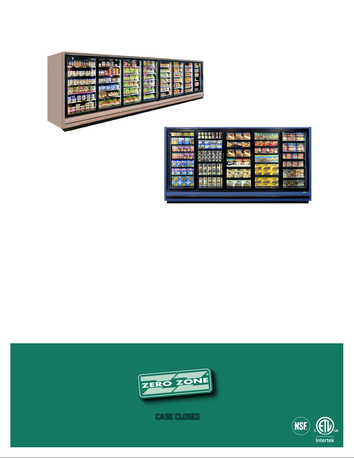
MEDIUM AND LOW TEMPERATURE
DISPLAY CASES
INSTALLATION & OPERATION MANUAL
CASE CLOSED
Rev A 1/7/13
Page 2

Page 3

TABLE OF CONTENTS
ZERO ZONE WARRANTY .................................................................. 1
INTRODUCTION .............................................................................. 2
Important User Information ........................................................ 2
Manufacturer ............................................................................ 2
Intended Use ............................................................................ 2
Display Case Models .................................................................. 2
Delivery Inspection .................................................................... 3
Packaging ................................................................................ 3
Location ................................................................................... 4
INSTALLATION ............................................................................... 5
Leveling ................................................................................... 5
MOVING CASES ............................................................................ 10
LINEUP ASSEMBLY ....................................................................... 12
DRAIN LINE ................................................................................. 16
BUMPER AND KICKPLATE ............................................................. 17
Installing End Kickplate ........................................................... 17
Installing Bumper ................................................................... 17
Under Case Return Air Flow Assembly Instructions ..................... 19
GENERAL INFORMATION .............................................................. 20
Cleaning ................................................................................. 20
Shelf Location ........................................................................ 20
Shelves .................................................................................. 20
Loading the Case .................................................................... 20
Light Switch ........................................................................... 21
Case Thermometer .................................................................. 21
Service ................................................................................... 21
REFRIGERATION ........................................................................... 23
General .................................................................................. 23
Low Temp ............................................................................... 26
Medium Temp ......................................................................... 28
ELECTRICAL ................................................................................. 29
General .................................................................................. 29
Low Temp ............................................................................... 32
Medium Temp ......................................................................... 36
DEFROSTING ................................................................................ 39
Low Temp ............................................................................... 39
Low Temp/Medium Temp ......................................................... 43
Medium Temp ......................................................................... 44
Page 4

Page 5

ZERO ZONE WARRANTY
LIMITED WARRANTY
Zero Zone, Inc. (Seller) hereby warrants that any products manufactured by it and sold are warranted to be free from defects in material
and workmanship, under normal use and service for its intended purpose, for a period of one (1) year from the date of original installation
(not to exceed 15 months from the date of factory shipment). The obligation under this warranty shall be limited to repairing or
exchanging any part, or parts, without charge, FOB Factory, and which is proven to the satisfaction of Zero Zone’s service department to
be defective. Zero Zone reserves the right to inspect the job site, installation, and reason for failure. This limited warranty does not cover
labor, freight, or loss of food or product, including refrigerant loss. This warranty does not apply to motors, switches, controls, lamps,
driers, fuses or other parts manufactured by others and purchased by the seller unless the manufacturer of these items warrants the
same to the seller and then only to the extent of such manufacturer’s warranty to the seller. Any products sold on an “AS IS” basis shall
not be covered by this warranty.
EXTENDED WARRANTIES
In addition to the standard limited warranty, for further consideration, the Company will extend to the original purchaser, a limited
extended warranty on the compressor only, following expiration of the standard warranty. The seller agrees to repair or exchange, at
its option, or provide reimbursement for such exchange as directed, less any credit allowed for return of the original compressor, of a
compressor of like or similar design and capacity, if it is shown to the satisfaction of Zero Zone that the compressor is inoperative due
to defects in factory workmanship or material under normal use and services as outlined by Zero Zone in it’s “Service and Installation”
instructions.
LENGTH OF EXTENDED WARRANTY
Any compressor warranty may be extended for an additional four (4) years but such extension must be purchased prior to shipment to
be effective. In those instances on manufactured systems where factory installed “Zero Zone Oil Management Systems” are purchased
the original limited warranty shall be extended automatically to two (2) years total and purchased extended warranties shall be extended
automatically for a total of six (6) years from the date of factory shipment. This warranty is only for the compressor and not for any other
associated parts of the refrigeration system.
PRODUCT NOT MANUFACTURED BY THE SELLER
The written Warranty, if any, provided by the manufacturer of any part of the refrigeration unit sold by Seller to Buyer, but not
manufactured by Seller, is hereby assigned to the Buyer. However, Seller makes no representation or Warranty regarding the existence,
validity or enforceability of any such written Warranty.
LIMITATION AND EXCLUSION OF WARRANTIES
THE WARRANTIES SET FORTH HEREIN ARE EXCLUSIVE AND IN LIEU OF ALL OTHER WARRANTIES AND REMEDIES WHATSOEVER,
INCLUDING, BUT NOT LIMITED TO, IMPLIED WARRANTIES OF MERCHANTABILITY AND/OR FITNESS FOR A PARTICULAR PURPOSE.
Zero Zone Warranty • 1
Page 6
INTRODUCTION
IMPORTANT USER INFORMATION
Copyright © 2013 Zero Zone, Inc.
All rights reserved. No part of the contents of this manual may be reproduced, copied, or transmitted in any form or by any means
including graphic, electronic, or mechanical methods or photocopying, recording, or information storage and retrieval systems without the
written permission of the publisher, unless it is for the purchaser’s personal use.
The information in this manual is subject to change without notice and does not represent a commitment on the part of Zero Zone. Zero
Zone does not assume any responsibility for any errors that may appear in this manual. In no event will Zero Zone be liable for technical
or editorial omissions made herein, nor for direct, indirect, special, incidental, or consequential damages resulting from the use or defect
of this manual.
The information in this document is not intended to cover all possible conditions and situations that might occur. The end user must
exercise caution and common sense when installing, using, or maintaining Zero Zone products. If any questions or problems arise, call
Zero Zone at 800-247-4496.
Any change to a Zero Zone product made during the installation, startup, or at any other time must be submitted in writing to Zero Zone
for approval and be approved by Zero Zone in writing prior to commission. The product warranty is voided when any unapproved change
is made to a Zero Zone product.
MANUFACTURER
Zero Zone, Inc.
Display Case Division
110 N Oakridge Dr • North Prairie, WI 53153 • 800-247-4496 • www.zero-zone.com
INTENDED USE
Zero Zone products are intended to be installed and used as described in this manual and other related Zero Zone literature,
specications, drawings, and data. Always install Zero Zone products on a level surface.
The information contained in this manual pertains to Zero Zone Display Cases, which include the following:
DISPLAY CASE MODELS
LOW TEMPERATURE DISPLAY CASES MEDIUM TEMPERATURE DISPLAY CASES
RVZC30 RMZC24 RVCC30 RMCC24
RVZC30T2 3RMZC30WA RVCC30T2 3RMCC30WA
RVZC30BB 3RVZC30WAT2 RVCC30BB 3RVCC30WAT2
RVZC30T2BB RVCC30T2BB
2 • Introduction
Page 7

INTRODUCTION
DISPLAY CASE MODELS (CONT.)
Zero Zone produces high quality refrigerated display cases using state-of-the-art components. The cases are built with the thickest
insulation in the industry and a high efciency evaporator coil. Potential case features include:
Brushless D.C. electronic motors, PSC*, or shaded pole fan motors*
T-8 uorescent lamps*
LED lighting
Standard-energy*, low-energy, or no-energy doors
These display cases were designed and tested using the following industry standards:
ASHRAE Standard 72-2005 — Method of Testing Commercial Refrigerators and Freezers (ANSI Approved)
AHRI 1200 — Performance Rating of Commercial Refrigerated Display Merchandisers and Storage Cabinets (ANSI Approved)
UL 471- Commercial Refrigerators and Freezers (ANSI Approved) (equipment certied by ETL)
NSF 7- Commercial Refrigerators and Freezers (ANSI Approved) (equipment certied by NSF)
DOE Compliant (All U.S. Sales)
ASHRAE 72-2005 species the test conditions for the equipment. It includes the ambient conditions of 75°F dry bulb and 55% RH.
It also species the door opening requirements for the performance test. Doors are opened 6 times in 1 hour for 6 seconds. The door
opening test period is for 8 hours during one 24-hour performance test. As an example, a 5-door case will have 240 door openings
during one 24-hour test. Consult the factory if your store exceeds these test conditions.
*Not for U.S. Sales
DELIVERY INSPECTION
These display cases were carefully factory-tested, inspected and properly packed to ensure delivery in the best possible condition.
The equipment should be uncrated and checked for damage immediately upon delivery. DAMAGE MUST BE NOTED AT TIME OF
DELIVERY AND ALL CLAIMS FOR DAMAGES MUST BE FILED WITH THE TRANSPORTATION COMPANY - NOT WITH ZERO ZONE.
The carrier will supply necessary report and claim forms.
PACKAGING
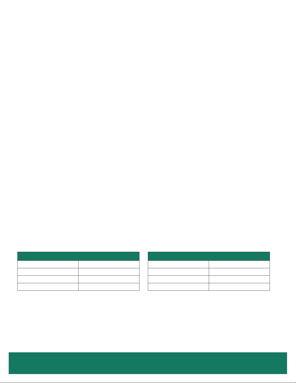
Each case in a lineup is labeled to identify the lineup and joint. The label uses a number and letter designation. The number indicates
the lineup. The letter indicates the case joint. Case joints begin with the letter A at the left most joint in the lineup when looking at the
front of the lineup. The joint for two cases has the same number-letter designation (Figure 1 on page 4). Back-to-Back cases have a
unique designation. The left most joint in the lineup when looking at the front of the case is labeled 1-A. The joint on the back of the case
is 1-A1 (Figure 1 on page 4).
Insulated dividers are factory installed to separate low and medium temperature cases. They are also used to join different case models.
Factory installed plexiglass dividers separate refrigeration circuits.
The rst case in the lineup (with the right side labeled “A”) has a packet attached to the door handle that contains the manual, special
instructions for installing ordered options, and touch-up paint if the cases are custom painted. Every case in the lineup has a packet
attached to the door that contains the specic information for that case. The packing slip is taped to the right-hand door of each case.
Bumpers and kickplates are shipped on top of the case. Shelves for the case are tie-wrapped and blocked into the individual cases. Other
accessories like drain traps, drain pans, condensate evaporation pans, and hat channels are shipped in the case that require the parts.
Materials for joining cases include caulk, joining bolts, splices, and T or J strips. These parts are supplied in cases that have a left-side
insulated divider or no left end. The parts are bagged and taped to the coil covers. The T and J strips are tied to the shelves.
Introduction • 3
Page 8
INTRODUCTION
LOCATION
These cases must not be installed in the direct rays of the sun or near a source of radiant heat.
Be certain that the oor under the installation is of sufcient strength to prevent sagging. Out of level conditions will result in reduced
performance.
Wall cases (cases set with a back to a wall) and cases set back-to-back, should be positioned to allow a minimum 2-4" space behind the
back of the unit(s). This will allow necessary air to circulate behind the display case(s). Higher humidity stores with minimal air circulation
require a 4" gap.
Figure 1: Case Label Information
4 • Introduction - Location
Page 9
INSTALLATION
LEVELING
Cases must be installed perfectly level to allow efcient operation of the
refrigeration coils and complete drainage of defrost water. Since a level
area is seldom available, the following steps are recommended to insure a
level installation.
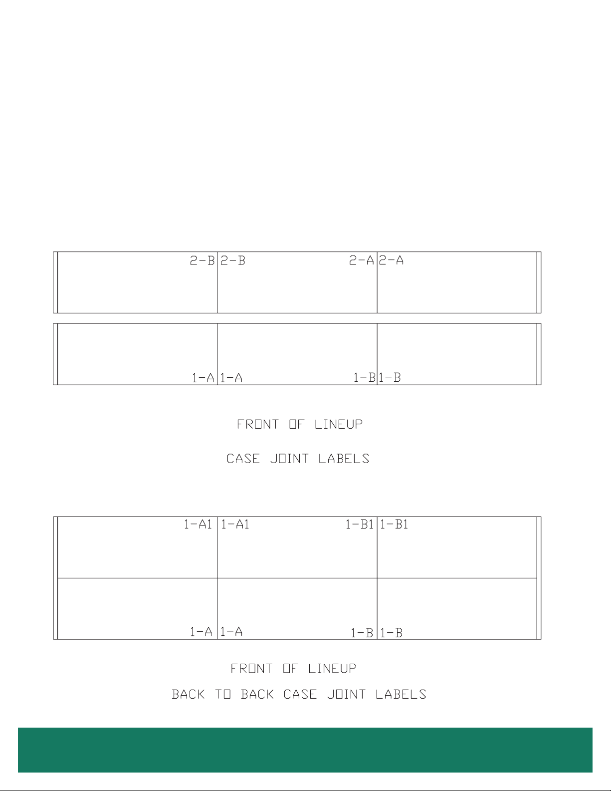
1. Measure off and mark on oor the exact dimensions of the case
lineup (Figure 2A). (Check blueprints).
2. Snap a chalk line at the locations for the front and back positions
of the bases.
3. Mark locations of all joints (front and back).
4. Using a laser or transit, nd the highest point along both base rail
position lines. Using the high point as a reference, mark the difference
directly on the oor to each joint, front and back (Figure 2B).
5. If you plan on using optional hat channels to raise the case height,
place them under each pair of bases. The 3 and 4-door hat channels
will be angled slightly to support the front and rear bases. (Figure 3
on page 6 and Figure 5 starting on page 7).
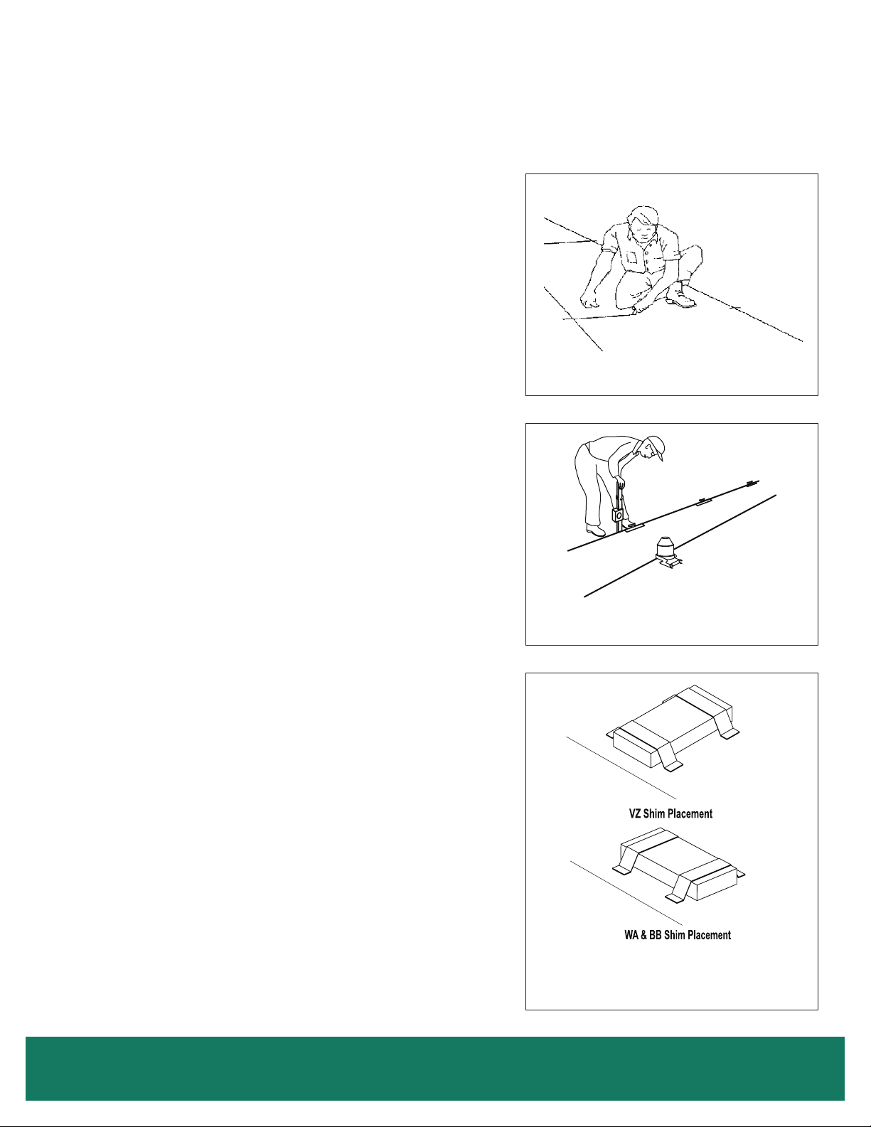
6. Place the required number of shims under each base or optional hat
channel at each joint (front and back) to equal the highest point.
7. The RVZC30, RMZC24, RVCC30 and RMCC24, 2 through 5-door
cases, have segmented bases mounted at the ends and under the
center section of the case. The RVZC30 and RVCC30 1-door and
RVZC30BB and RVCC30BB have full bases that run front to back
and are located at the ends and under the center sections of the case.
The 3RMZC30WA and 3RMCC30WA have segmented bases that run
front to back.
8. Tape all shims in place (Figure 2C). Figure 4 on page 6 shows
the correct orientation of shims under the base or channel.
Figure 2: Leveling Cases Prior to Joining
A. Measure and mark exact case outline
B. Mark oor level differences
9. Place additional support shims under all other bases or hat channels
(Figure 5 starting on page 7).
10. Use a carpenter’s level to check installation as you go. The case
should be level from front to back and side to side. Install the case
at the highest point rst, if part of a lineup. Check the level on the
face of the glass doors and sides of the mullions. Do not use the
ceiling to check level.
11. If you’ve purchased seismic restraints, specic instructions for
attaching those restraints are included in your document package.
These instructions should be read and followed before the lineup
is assembled.
C
a
s
e
F
ro
nt
Case Fro
nt
C. Shim joints to equal highest points
Installation - Leveling • 5
Page 10
RELEASED
INSTALLATION
RELEASED
LEVELING (CONT.)
Figure 3: Typical Hat Channel Locations
Base
Shim
Base
Shim
Hat Channel
Case
Figure 4: Shims Under Bases and Case
Shims
Shims
DWG. NO. SP-6003-1 REV. A
Case
Both corners of the base
must be supported by shims
to prevent base buckling
6 • Installation - Leveling
DWG. NO. SP-6006-1 REV. A
Page 11
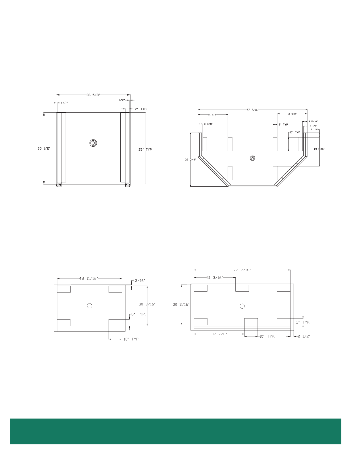
INSTALLATION
LEVELING (CONT.)
Figure 5: All Base Locations
A. 1-Door Case B. Wrap Around Case (WA)
C. 24" 2-Door Case D. 24" 3-Door Case
Installation - Leveling • 7
Page 12
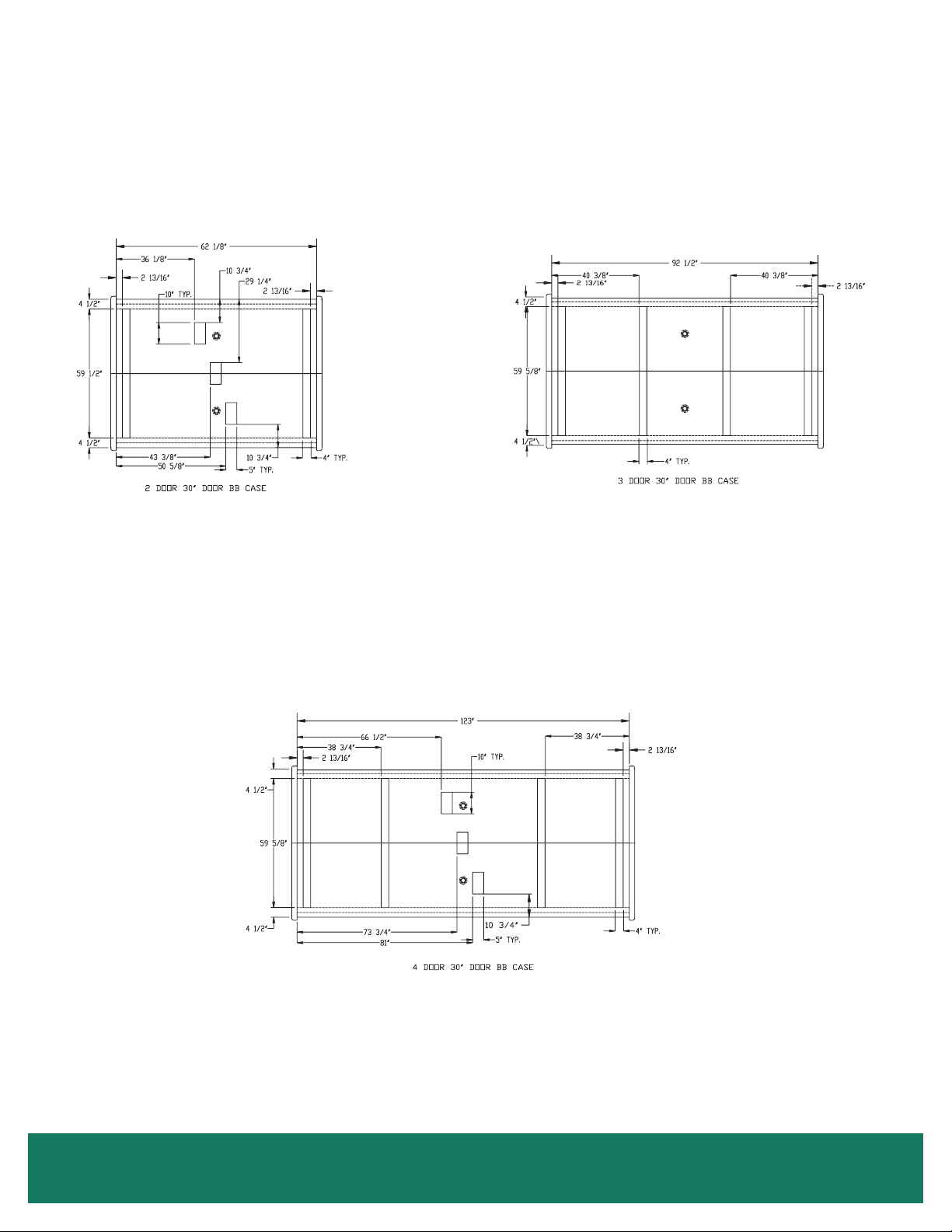
INSTALLATION
LEVELING (CONT.)
E. 30" 2-Door Back-to-Back Case F. 30" 3-Door Back-to-Back Case
Figure 5: All Base Locations (Cont.)
8 • Installation - Leveling
G. 30" 4-Door Back-to-Back Case
Page 13
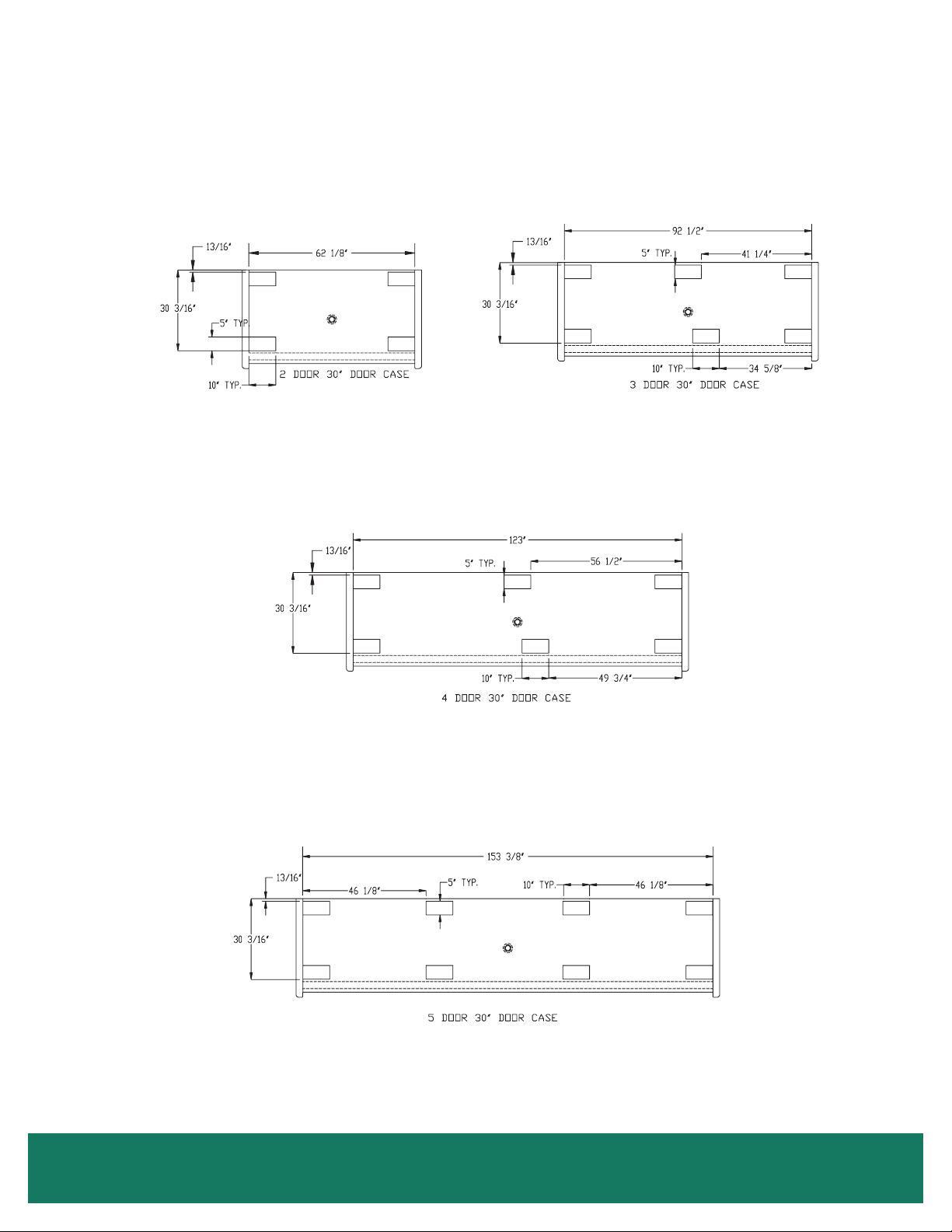
INSTALLATION
LEVELING (CONT.)
Figure 5: All Base Locations (Cont.)
H. 30" 2-Door Case
I. 30" 3-Door Case
J. 30" 4-Door Case
K. 30" 4-Door Case
Installation - Leveling • 9
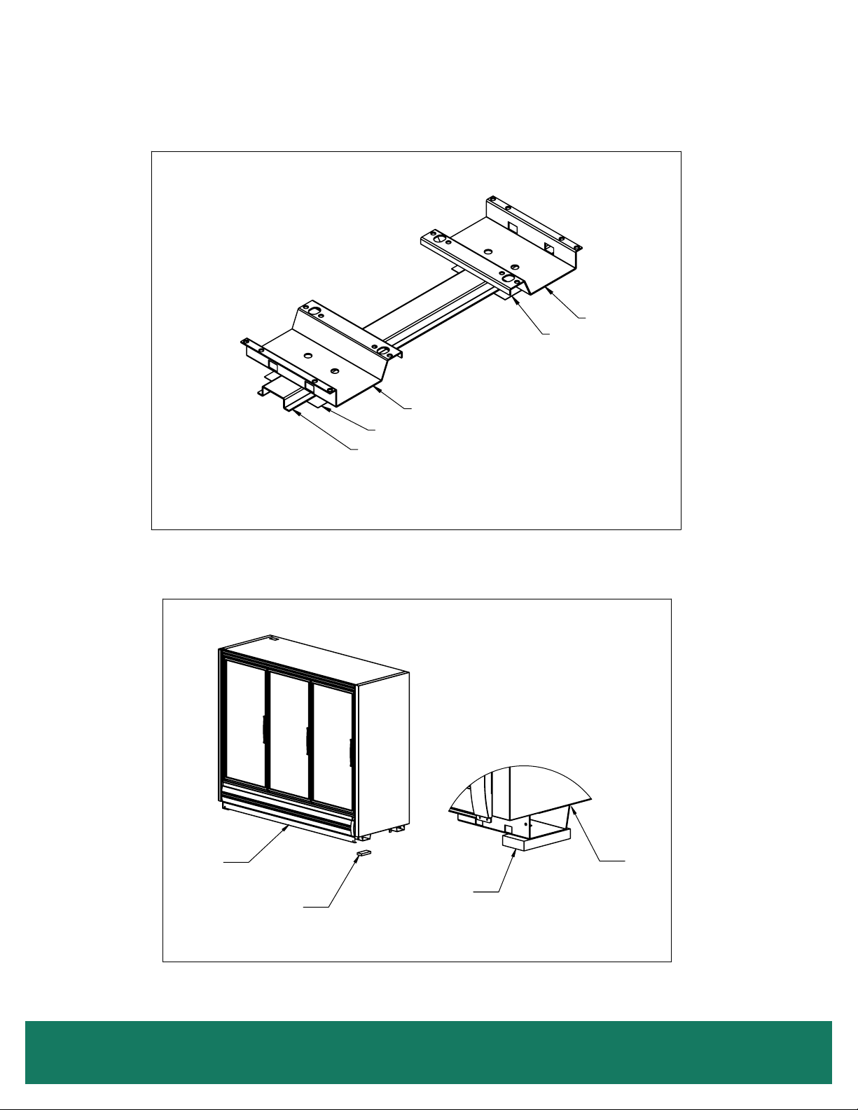
Page 14

MOVING CASES
The Back-to-Back cases are shipped with wood planks that allow the use of pipe rollers. These wood planks should be removed after the
case is moved to its nal location (Figure 6 on page 11).
The RVCZ and RVCC and BB cases have steel protective support plates under the ends (not under insulated dividers). These are
designed to protect the end from Johnson Bar damage.
Use the following methods to move the cases:
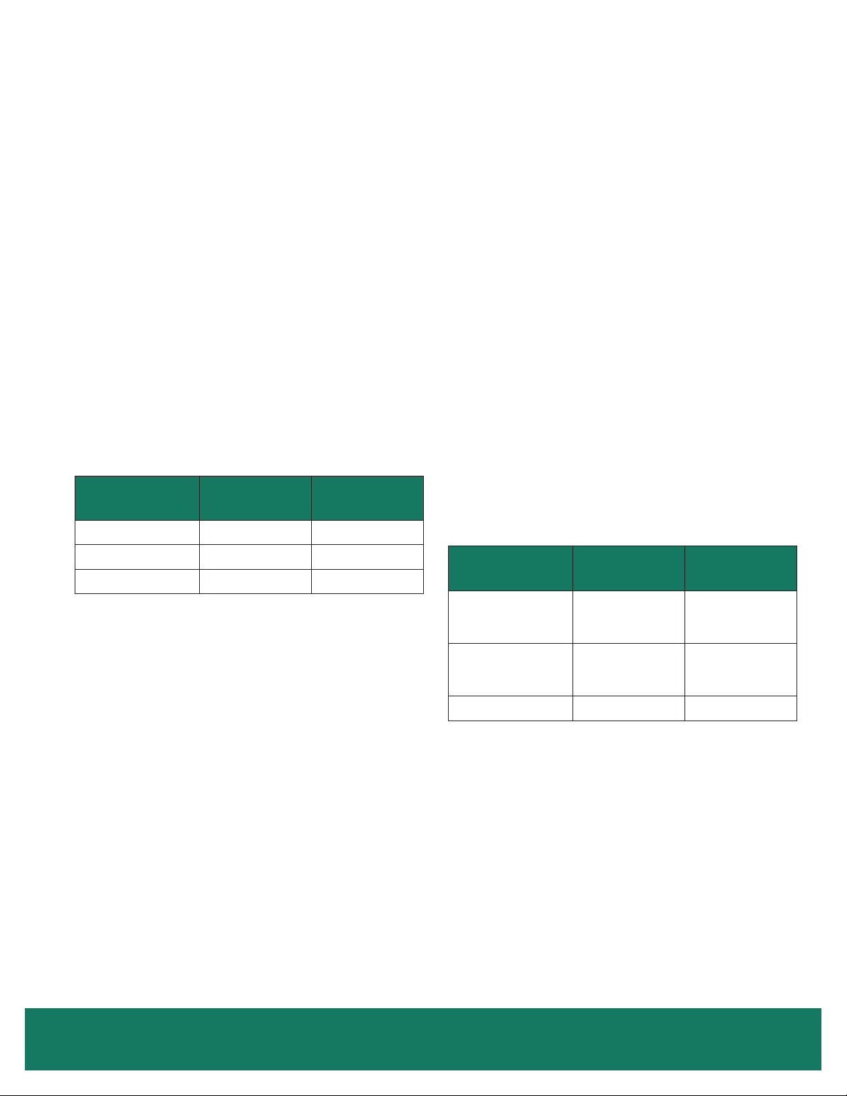
MODEL
RVZC30 & RMZC24
RVZC BB
RVZC WA
1-Door RVZC
RVCC30 & RMCC24
RVCC BB
RMCC WA
1-Door RVCC
* Fork lift from rear
Care should be taken when moving the cases. The doors should be secured so they cannot open while the case is moved.
Only experienced certied fork truck drivers should use fork trucks to move the cases. The case should only be lifted off the oor as high
as necessary for transport. The fork truck should be driven slowly avoiding any abrupt motions or bumps.
The cases have steel protective support plates under the ends (not under insulated dividers). These are designed to protect the end
panel from J-bar damage.
Care should be taken when moving the cases. The doors should be secured so they cannot open while the case is moved.
FORK LIFT
FROM ENDS
*
*
*
JOHNSON
BAR
FURNITURE
DOLLY
PIPE
ROLLERS
SAFE (CASE)
JACKS
Only experienced certied forklift drivers should use forklifts to move the cases. The case should only be lifted off the oor as high as
necessary for transport. The forklift should be driven slowly, avoiding any abrupt motions or bumps.
The following forklift dimensions must be maintained to avoid damaging the case when it is lifted:
2-DOOR CASES
Forks must extend from 26" to no more than 30" under the case.
3-DOOR CASES
Use 48" long forks!
Forks must extend from 39" to no more than 43" under the case.
4 & 5-DOOR CASES
Use 48" long forks!
Fork blades wider than 4" will not t in the bases.
10 • Moving Cases
Page 15
MOVING CASES
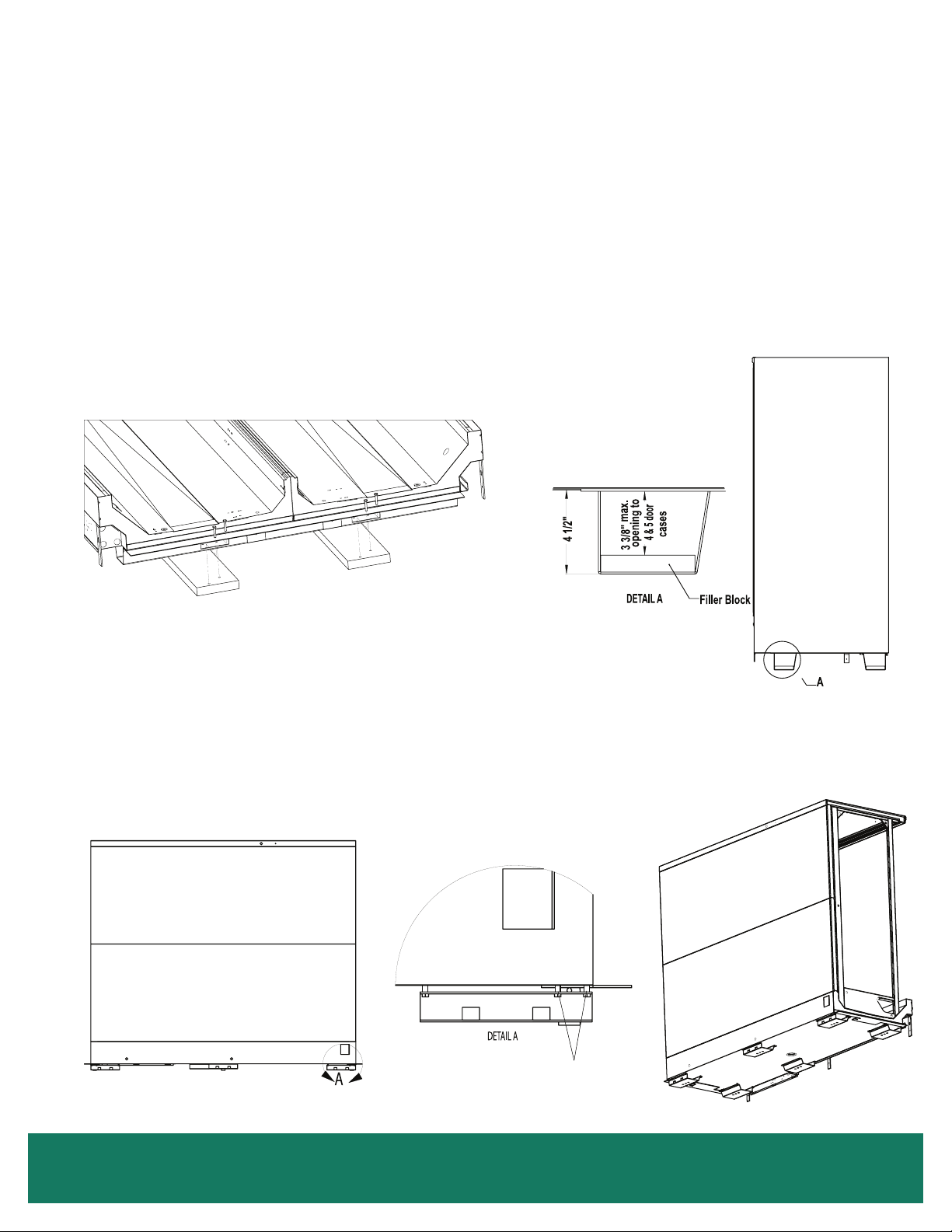
Spacer blocks are factory installed in the end bases of 4 and 5-door cases that use 4 ½" bases (Figure 7). These blocks limit the cases
forward tilt while it is being lifted and must be used when lifting 4 or 5-door cases with 4 ½" bases.
For low shipping height applications, Zero Zone has optional expandable bases. As shipped, the base is 1¾" tall. It is attached with
spacers that allow the base to slide away from the bottom of the case creating a gap that allows the use of a 1½" thick fork truck blade
(Figure 8).
Figure 6: Removing Wood Planks
Figure 7: Wood Block Inside Base
Figure 8: Expandable Base
Spacers
Moving Cases • 11
Page 16

LINEUP ASSEMBLY
RELEASED
Zero Zone display cases have been engineered for continuous display. This means that any number of cases can be joined together to
create a display of any desired length. The bottom of the end panel is protected with a removable steel plate.
The lineup is assembled by sliding one case up to the second case and then bolting the cases together. Bolt holes for the bottom of the
frame can be accessed by removing the right and left coil covers. The front and top bolt holes are visible on the steel end frame. The rear
bolt holes are exposed by removing the lift-out duct on the 30" door cases and by removing pocket covers on the 24" door cases. Figure
12 on page 13 show the bolt hole locations for each case. Bolt kits and instructions are supplied with the case.
Figure 9 gives instructions on applying caulk to the case joint before the cases are slid together. Once the cases have been caulked and
slid together, start the joining bolts, but do not tighten them. Slide the t-strip between the door frames (Figure 11 on page 13). Begin
tightening the bolts at the top rear, working down the back of the case and up the front, making sure that the front seams are ush. Bolts
are not designed to pull the cases together.
Two different model cases or two different temperature cases are connected using an insulated divider. Typically the divider is factory
assembled to one of the cases. Two styles of divider are provided. The rst style has a panel on each side with nut inserts in the panels.
Each side is bolted to the end frame. Instructions for assembly of this style are given in Figure 13 on page 14. The second style
divider uses a thru-bolt design. The divider is attached to one of the cases using short bolts. When the case is installed, the short bolts
are removed and long bolts are reinstalled to bolt both cases together. Instructions for assembly of this style case are given in Figure 14
on page 15. Bolts are not designed to pull the cases together.
For NSF case installation, the interior case seams need to be sealed using NSF approved caulk (not supplied) as shown in Figure 10 on
page 13.
The end panel protector support plates should be removed after the cases are set in their nal position.
Figure 9: Caulking Cases to be Joined
DO NOT APPLY EXCESS AMOUNTS OF BUTYL SEALANT THAT WOULD CAUSE IT TO SQUEEZE ONTO END FRAME
METAL AREAS. Caulk sealant used to join cases and complete the sealing requirements for NSF compliance should not come
in contact with butyl sealant. Apply to clean, dry surfaces free of contaminants that adversely affect adhesion and could change
color of sealant joint areas over time.
B
A
DETAIL A
DETAIL B
Remove (4) Filler Blocks If
Applied To Inside Of Base
Ends Before Joining Cases
1/4" - 3/8" Typ.
Butyl Sealant
Beads
1/4" - 3/8" Typ.
Butyl Sealant
Beads
PROCEDURE FOR JOINING CASES
These procedures are critical! Failure to follow these guidelines
will result in a poorly functioning case. This is especially true of
low temp cases.
1. Apply two ¼" to 3/8" wide beads of butyl sealant, ½" in from
2. When joining ends of cases, caulk sealant should be applied
the inside and outside edges of foamed insulated ceiling, rear
wall, base, and door frame to be joined. Apply to only one
case joint to avoid excessive amounts of butyl sealant that
would squeeze out of the joint. Sealant is not applied to the
structural steel end frames. After cases are joined, caulk the
top and back exterior seams (if possible) at this time.
in the same manner for joints.
12 • Lineup Assembly
DWG NO.SP-6005-1REV. B
Page 17

LINEUP ASSEMBLY
RELEASED
RELEASED
Figure 10: Required Sealing for NSF-Approved Installations
Caulk Here
SURFACE TEMPERATURE SHOULD BE ABOVE
40°F AND FREE OF FROST.
1. Apply nonporous/nonabsorbent good quality NSF
approved silicon caulk sealant or (Manus Bond
75-AM) after end panel is joined to case or when
second case is joined with rst case.
2. Apply silicon caulk-sealant bead to areas shown
to meet sealant requirements for NSF approved
installations.
Caulk Here
3. Apply small beads of sealant smoothly, but do not
thin or feather excessively, because it may affect
adhesion.
Remove End Protection
Plate Located Below End
On Outside Of Case
DWG NO.SP-6005-2REV. B
NOTE: Field caulk is applied continuously.
Figure 11: T-Strips Figure 12: Joining 24" and 30" Door Cases
3
Joining 24" & 30" Cases
2
End frames factory installed.
Exploded for clarity.
DETAIL A
Typ (5) Places
2
1
A
5
4
Joining Frames
Typ (4) Places
Caulk Case Joints
Per I&O Manual
DWG NO. SP-0537 REV.H
Lineup Assembly • 13
Page 18

LINEUP ASSEMBLY
4.250
5.500
4.250
5.500
RELEASED
Figure 13: Joining Insulated Dividers with Nut Inserts
2-1/2" Insulated Divider Joining Kit
Case to be joined
not shown
3
1
Insulated
divider
(factory
attached)
3
2
4
For attaching
frames
Caulk case joints per I&O manual.
DWG NO. SP-0397 REV.H
14 • Lineup Assembly
Page 19

DESCRIPTION
BOLT HEX TAP 1/4-20 x 3-1/2" HEX HD BOLT, GRD 8
NUT HEX 1/4-20 GRD 8
WASHER 9/32" ID 1-1/4" OD .093TK FNDR
SCREW #10 X 1.0" PH FLTHD SMSZP (FRAME)
ADD FOR JOINING KIT
GALV. SHIM 2" X 6" (LEVELING CASE)
QTY
(5 )
(5 )
(10 )
(4 )
(25 )
ITEM
1
2
3
4
5
SP-1097 REV C
ZZ PART NO.
64-0406
64-0308
64-0199
64-0269
ZZ PART NO. BLACK
64-0406-P1
64-0308-P1
64-0199-P1
64-0269-P1
2-1/2" INSULATED DIVIDER JOINING KIT WITH THRU BOLTING
VZ TO VC VC TO VZ VZT2 TO VCT2 OR VCT2 TO VZT2
1) CAULK CASE JOINTS FOLLOWING SP-0420 TECH BULLETIN
CASE JOINING AND SEALING NSF FIELD CAULKING.
2) ALIGN OPPOSITE ENDS OF TWO CASES TO BE JOINED.
3) THERE ARE 5 BOLTS ATTACHING THE DIVIDER TO THE
CASE. REPLACE EACH OF THESE BOLTS ONE AT A TIME.
DO NOT REMOVE DIVIDER FROM CASE.
3a) REMOVE ONE BOLT AND ONE WASHER USED TO
ATTACH 2-1/2" INSULATED DIVIDER PANEL.
3b) INSTALL ONE LONGER (ITEM 1) 1/4-20 X 3-1/2" GRADE
8 BOLT AND ONE (ITEM 3) WASHER IN THE SAME
LOCATION AND ORIENTATION OF THE ORIGINAL BOLT.
3c) TIGHTEN TO SECURE INSULATED DIVIDER. THE BOLT WILL
TIGHTEN TO THE PANEL AND THE END OF THE BOLT WILL
EXTEND THRU INTO THE NEXT CASE.
3d) REPEAT UNTIL FIVE BOLTS HAVE BEEN REPLACED.
4) HAND TIGHTEN ITEM 3) WASHERS AND (ITEM 2) GRADE 8
NUTS ON OPPOSITE CASE.
5) MAKE SURE INSULATED DIVIDER IS ALIGNED WITH CASE.
6) ALTERNATELY TIGHTEN EACH BOLT EQUALLY UNTIL THE
CASES ARE JOINED TOGETHER EVENLY FORMING A TIGHT
SEAL BETWEEN THE DIVIDER AND THE CASE. BOLTS ARE
NOT DESIGNED TO PULL CASES TOGETHER.
7) FINISH ATTACHMENT OF THE SECOND CASE FRAME WITH
FOUR (ITEM 4) SCREWS.
6.500
5.500
3
2
3
1
CASE
DIVIDER
CASE
BOLT DETAIL FOR
RIGHT INSUL DVDR
LEFT OPPOSITE
2-1/2" INSULATED DIVIDER
(RIGHT SHOWN, LEFT OPPOSITE)
(FACTORY INSTALLED)
4
4
CASE
CASE
LINEUP ASSEMBLY
Figure 14: Joining Insulated Dividers with Thru-Bolts
Lineup Assembly • 15
Page 20

DRAIN LINE
RELEASED
The drain is located at the center of the case in the oor pan. The drain can be reached by removing the center coil covers and then
removing a fan motor. The 1" PVC drain outlet is located at the center front of the case behind the kickplate.
Install the tee to the outlet pipe and a drain trap to the tee. Plug the open end of the tee using the clean-out plug supplied with the drain
trap kit. The drain line must be pitched away from the case. The tee, drain trap and plug are supplied with the case. The factory installs
a drain support at the front of the case on all 30" door cases. We supply a trap support that is eld mounted to the case (Figure 15). The
drain trap must be level. The drain trap should be primed with water after installation. The drain line must be pitched away from the case
enough to insure proper drainage. Consult your local codes for minimum requirements.
Figure 15: Trap Support
16 • Drain Line
Drain Trap Support
Drain Support
DWG NO.SP-6000-1REV. B
Page 21

BUMPER AND KICKPLATE
A Zero Zone bumper is standard on all case models and should be installed at the bottom front of the case. Various bumper styles are
available (Figure 16 on page 18). The kickplate assembly is adjustable to compensate for uneven oors. The bumper end cap is
factory installed on bumpers for cases with end panels that do not include Euro trim.
INSTALLING END KICKPLATE
(Figure 17 on page 18)
The end kickplate attaches to the small black bracket attached to each side of the case with an end. The kickplate can be adjusted
vertically to match the height of the oor below it.
1. Attach a Tinnerman clip to the side bumper support.
2. Place the side kickplate against the Tinnerman clip on the side bracket.
3. Install the black ¾" screw through the side kickplate and into the Tinnerman clip. A scratch-awl or similar tool can be used to line up
the holes.
4. The front of the side kickplate is located behind the front kickplate and attached with screws to the front kickplate.
INSTALLING BUMPER
(Figure 17 on page 18)
The front kickplate and bumper attaches using 1½" screws attached to brackets located on the front of the case. The kickplate can be
adjusted up and down to t the height of the oor below it.
1. Starting from the left end of the lineup, attach a Tinnerman clip to each bumper support bracket. Locate them over the hole for the
bumper.
2. Attach the kickplate splice to the right side of the kickplate using the ¾" screw in the lower hole.
3. Lean the kickplate against the bumper support bracket.
4. Hang the bumper on the case. The kickplate should be located behind the bumper.
5. Install the black 1½" screw through the bumper, kickplate, kickplate splice, and into the Tinnerman clip. A scratch-awl or similar tool
can be used to line up the holes.
6. Follow these steps to install the next bumper in the lineup. A bumper splice (provided) should be installed between the two cases.
Center the splice and adjust the height so the decorative tape (if applicable) lines up. Using self-tapping screws (provided), attach
the upper portion of the splice using the predrilled holes in the splice. Then with two more screws, attach the lower half.
Bumper and Kickplate • 17
Page 22

BUMPER AND KICKPLATE
RELEASED
RELEASED
Figure 16: Other Style Bumpers
Bumper Hanger
PVC Bumper
Kick Plate
Zero Zone PVC
Bumper Hanger
Bumper
Support
After Market
Aluminum
Bumper
Support
Support
Bracket
Kick plate
Zero Zone Aluminum Typical After
Bumper
Bracket
Kick plate
Figure 17: Installing Bumper and Kickplate
Bumper
Market BumperBumper
DWG NO.SP-6002-1REV. B
Support
Bracket
End Kick Plate
Kick Plate
Bumper End Cap
Bumper
Bumper Splice
Case
Electrical Box
Bumper End Cap
End Kickplate
DWG NO.SP-6001-1REV. B
18 • Bumper and Kickplate
Page 23

BUMPER AND KICKPLATE
UNDER CASE RETURN AIR FLOW ASSEMBLY INSTRUCTIONS
To assemble the bumper for under case return air ow (if requested), a spacer (provided) must be inserted between the bumper and
kickplate (Figure 18). The spacer is held in place with the standard black assembly screw used to attach the bumper. One 3/8" spacer is
required at each screw location (2 spacers on a 2-door, 3 spacers on a 3-door, etc.).
1. To ease installation, hook the bumper to the case and position the kickplate. Then pull the bottom edge of the bumper forward,
hold the spacer in place, and then insert the assembly screw through the bumper, spacer, kickplate, bumper bracket and into the
Tinnerman clip.
2. With the spacers in place, air will be allowed to ow between the bumper and kickplate and then underneath the case. The target
airow rate under the case should be 50 cfm/door.
Note: An optional louvered kickplate is available.
Figure 18: Bumper Air Flow
Bumper and Kickplate • 19
Page 24

GENERAL INFORMATION
CLEANING
The case and doors are cleaned prior to shipping. However, the case should be thoroughly cleaned before start-up and routinely
thereafter to maintain a clean appearance. Use mild detergent and warm water (never an abrasive cleaner) to wipe out the inside of the
case. Wash down all glass doors with glass cleaner. Do not use any products containing silicon on anti-fog glass coatings. Clean interior
glass reduces fogging and increases visibility. The case will remain bright and sparkling with just a few minutes of cleaning each week.
Internal components can be cleaned after removal of access panels. The case drain should be regularly cleared of debris and price tags.
Coils may be cleaned with a garden hose or pails of water. Cases that use pump, drain pans and condensate evaporators should be
cleaned with a minimum amount of water. The drain should be blocked and the water removed with a shop vacuum.
Do not use high-pressure water or steam to clean the interior.
SHELF LOCATION
The shelves are adjustable in 1" increments on cantilever shelf cases and may be located in any position for best display advantage.
Be sure brackets are completely seated.
Wire shelf brackets are stamped with “R” for Right and “L” for left to aid installation.
SHELVES
Zero Zone manufactures many different styles of shelves, baskets, and product stops. The shelves and baskets are placed on the shelf
brackets for shipping. Solid shelves have three parts. A solid center section and two snap-in brackets. Some of the baskets may be
reversed and used as a typical shelf. The fully assembled shelves are installed in cases prior to shipping.
Solid shelves can be disassembled for cleaning. A screwdriver can be used to spread the snap open to remove the brackets from the
center section.
LOADING THE CASE
The case may be loaded with merchandise after it has been operated for at least 24 hours with correct case temperature and proper
control operation. While loading the shelves, leave an air space between the top of the merchandise and the shelf above it so the
customer can remove the merchandise. The air space allows an air curtain on top of the product. Product should not extend beyond the
front of the shelves or block the return air grill.
The shelf loads are as follows:
ITEM
1 22" and 24" deep 250 lbs.
2 27" deep 400 lbs.
3 Bakery or Meat Brackets
SHELF DESCRIPTION
at 0° 250 lbs.
at 5° 250 lbs.
at 10° 150 lbs.
at 15° 100 lbs.
MAXIMUM LOAD PER SHELF
Some deection may occur under higher loads.
20 • General Information
Page 25

GENERAL INFORMATION
LIGHT SWITCH
The light switch is located inside the right-hand door. Turn the light switch off during the initial case temperature pull down to prevent the
case lights from cycling off and on. Always turn the lights off when replacing lamps.
CASE THERMOMETER
The cases are shipped with 2 thermometers. One thermometer is factory mounted in the discharge air stream. The second thermometer
is shipped loose and should be installed in the warmest product location. Specic instructions are packaged with the shipped loose
thermometer.
SERVICE
See Figure 33 on page 41 and Figure 35 on page 43 for the typical component layout of the 30" door case. See Figure 34 on
page 41 and Figure 36 on page 43 for the typical component layout of the 24" door cases.
The bumper and kickplate must be removed to gain access to the drain clean out and electrical connections. Disassemble the bumper
and kickplate by removing the 2 or 3 metal screws located in the kick rail. The bumper assembly can be lifted up and removed from the
case. The kickplate can be removed, exposing the electric tray cover and drain (Figure 17 on page 18).
EVAPORATOR
The evaporator coil, located at the rear bottom of the case, is factory assembled with distributor, expansion valve, and other refrigeration
components. To inspect the coil, remove the center or left of center coil cover. A small inspection window is located at the rear of the
case. To inspect the entire coil, remove the remaining coil covers and raise the evaporator cover.
EXPANSION VALVE
Unless otherwise specied, a superheat adjustable externally equalized thermostatic expansion valve with a removable strainer and
pressure limiting charge (low temp only) is mounted to the evaporator coil. The valve is not preset. Adjust the superheat setting for
maximum coil effectiveness. Typical superheat settings are between 6°F and 10°F. Close coupled systems should use the higher
superheat setting to minimize the chance of liquid ood back. To adjust the expansion valve, remove the right end coil cover. Remove the
cap from the bottom of the valve. When looking at the valve stem end, turn the valve stem counterclockwise to decrease superheat. Turn
the valve stem clockwise to increase super heat. Measure the suction line temperature at the expansion valve sensing bulb and compare
it to the suction temperature corresponding to the saturated pressure. Make sure that line pressure drop is taken into account.
Turn the valve stem only ¼ turn at a time and allow sufcient time (20 to 30 minutes) for the valve to settle before making any further
adjustments. Replace the valve stem cap after the valve superheat has been adjusted. BE CERTAIN THE VALVE STEM CAP IS WIPED
DRY FIRST.
Caution! DISCONNECT POWER TO THE CASE BEFORE SERVICING ELECTRICAL COMPONENTS TO AVOID
!
PERSONAL INJURY AND DAMAGE TO THE UNIT.
EVAPORATOR FANS
Air is circulated throughout the case with 115 volt low temperature fan motors. These motors must be operating at all times except during
defrost in low temp cases. Fan motors should be replaced with motors having the same characteristics including type, physical size,
lubricant temperature range, wattage and RPM. Fan blades should be replaced with factory original equipment part.
General Information • 21
Page 26

GENERAL INFORMATION
SERVICE (CONT.)
CONDENSATE EVAPORATION SYSTEM
Zero Zone remote cases can be equipped with an automatic condensate evaporation system. The system uses a pump and drain pan
located behind the kickplate and a condensate evaporator pan mounted on the top of the case.
Condensate water and any liquid spilled in the case drains out into the drain pan. The pump is equipped with a oat that turns the
pump on when there is a sufcient liquid level. Liquid is pumped through a plastic hose through a check valve and into the condensate
evaporation pan. The evaporation pan is equipped with a heater and a oat switch to turn on when the heater is submerged in liquid.
When the heater is energized, the pan will be extremely hot and should not be touched. The pump and condensate pan should be
cleaned regularly. Any spilled product should be cleaned to prevent odors.
AIR CURTAIN VELOCITY
Air curtain velocity is affected by stocking levels, coil frost loads, temperature and fan condition. The measurement method also affects
the reading. Zero Zone recommends using an Alnor Velometer Jr., set to the 0-to-800 fpm range. Air velocity should be measured at the
back edge of the discharge air honeycomb, at the center of the middle door in the case (other doors have slightly lower velocity). A typical
low temp velocity reading is 400 to 500 feet per minute in a fully-packed low temp case, after the case has defrosted and pulled down
to operating temperature. Air curtain velocity in a partially-packed display case is signicantly lower because more air exits the back wall
duct holes. In medium temp cases, the velocity should be 300 to 400 feet per minute after the case has defrosted and pulled down to
temperature.
FAN REMOVAL
1. Turn off power to fans. Remove coil cover.
2. Unplug fan from fan power supply plug located on the front face of the fan housing.
3. Remove the fan blade nut and fan blade.
4. Remove the two mounting bolts and remove the fan assembly from the fan housing.
5. Remove the three fan motor mounting screws from the back of the fan motor.
6. Reverse steps 1 - 5 to install.
LED POWER SUPPLIES AND BALLASTS
Most Zero Zone case ballasts or LED power supplies are located in the door mullion. Ballasts for the 1-door and WA, are located behind
the kickplate.
FLUORESCENT LIGHTING
These systems use a lens to direct light output evenly across the shelves. Turn off power before servicing the lamps. The lens must be
removed to access the lamp. The lens must be replaced after servicing for proper operation. Detailed information is contained in the door
instruction booklet.
22 • General Information
Page 27

REFRIGERATION
RELEASED
GENERAL
Unless otherwise specied, the liquid
and suction connections are made
inside the case under the evaporator
fan/coil cover. Refrigerant piping
may enter the case through the front
left bottom, the left rear bottom of
case, or the left rear top of case.
The copper pipe should not touch or
rub on the edges of the sheet metal.
After connections have been made,
the refrigeration access hole in the
case must be sealed completely
with an aerosol-dispensed Urethane
insulation or equivalent (i.e. Great
Stuff). Penetrations made in sheet
metal bafes should also be sealed
(Figure 19).
Fill in area with
foam after
installation
Figure 19: Penetration Sealing
Fill in area with
foam after
installation
DWG. NO. SP-6007-1 REV. A
REFRIGERANT PIPING
Correct refrigeration line sizing and installation is essential for proper system operation. Figure 23 on page 26, Figure 24 on page
27, and Figure 25 on page 28 are for Evolution (V) model cases. Contact the factory for line sizing for the Maximizer (M) model
cases. A P-trap must be installed at the bottom of all vertical suction risers (Figure 20 on page 24). Various risers are available as a
factory installed option.
When two or more case sections are connected to one compressor, the main liquid and suction line for the group should be run through
the cases and be brought out through the refrigeration outlet of one case only. The factory recommends one riser per circuit/system for
hot gas defrost when using top back refrigeration exit. Circuit risers are available as a factory installed option. On 30" wide door cases
with suction lines over 1 3/8" diameter, a P-trap made with 45° elbows is required (Figure 20 on page 24). A piping chase in front of
the fan shroud allows the refrigerant lines to be run through the right or left end frame.
Piping should not be placed near the electric defrost heaters. The defrost heaters on the 30" door cases will grow one inch to the left of
the coil when they reach operating temperature.
The compressor should be installed as close as possible to the cases to reduce pressure drop. Install a shallow trap at the bottom of the
riser.
The best location for the liquid line drier is inside the case compartment. However, it may be installed near the compressor for easy
maintenance. Install moisture indicating sight glass at the outlet end of the drier.
A low pressure or temperature control can be used to control case temperature. The control should be selected with adequate contact
capacity for the switching load. In rack systems, an evaporator pressure-regulating valve may be used to control the evaporating
temperature.
The settings (Figure 21 on page 25) are approximate due to variations in gauge accuracy, differences in compressor efciency, line
pressure drop and superheat settings. Before making adjustments for store or stocking conditions, make sure the superheat is set.
Close coupled systems typically run at the higher end of this range to avoid ood back.
Refrigeration - General • 23
Page 28

REFRIGERATION
GENERAL (CONT.)
TEMPERATURE CONTROL ADJUSTMENT
When factory installed, the temperature control is located toward the right end of the case in the electrical box. The sensing bulb is
located under the coil cover on the back side of the fan shroud. It can be wired in series with the low-pressure (L.P.) control. It can also
be used in a pump down system by wiring it in series with the liquid solenoid valve. A thermostat is shown in Figure 22 on page 25.
Discharge air temperature probes for electronic case controllers may be installed in many different customer specied locations
including, but not limited to, honeycomb, ceiling pocket cover, rear wall, and return air.
LEAK-CHECK/EVACUATION/CHARGING
After all of the refrigeration piping and system components have been assembled, the entire system must be pressurized and checked
for leaks.
When the system is leak free, evacuate with a deep vacuum pump. Triple evacuation to a minimum of 500 microns and nitrogen sweep
is recommended. After the system has been thoroughly evacuated of all moisture and non condensable gas, charge the system with the
proper refrigerant, using “hi-side/low-side” charging techniques.
Figure 20: 45° Elbow Suction Line
24 • Refrigeration - General
Page 29

REFRIGERATION
RELEASED
GENERAL (CONT.)
Figure 21: Temperature Settings
R 404A FROZEN FOOD
RACK SYSTEMS
VZ and VZT 30" door
Evaporator temp -7°F
MZ 24" door and WA
Evaporator temp -11°F
CONDENSING UNIT
VZ and VZT 30" door
Condensing unit cut-in 35 psig
Condensing unit cut-out 24 psig
MZ 24" door and WA
Condensing unit cut-in 33 psig
Condensing unit cut-out 21 psig
RETURN & DISCHARGE
AIR TEMPERATURE
Return air temp cut-in +6°F
Return air temp cut-out 0°F
Discharge air temp cut-in +3°F
Discharge air temp cut-out -3°F
R 404A ICE CREAM R 404A MEDIUM TEMP
RACK SYSTEMS
VZ and VZT 30" door
Evaporator temp -16°F
MZ 24" door and WA
Evaporator temp -18°F
CONDENSING UNIT
VZ and VZT 30" door
Condensing unit cut-in 27 psig
Condensing unit cut-out 16 psig
MZ 24" door and WA
Condensing unit cut-in 26 psig
Condensing unit cut-out 15 psig
RETURN & DISCHARGE
AIR TEMPERATURE
Return air temp cut-in -3°F
Return air temp cut-out -9°F
Discharge air temp cut-in 0°F
Discharge air temp cut-out -12°F
RACK SYSTEMS
VC and VCT2 30" door
Evaporator temp +28°F
MC 24" door and WA
Evaporator temp +25°F
CONDENSING UNIT
VC and VCT2 30" door
Condensing unit cut-in 74 psig
Condensing unit cut-out 62 psig
MC 24" door and WA
Condensing unit cut-in 70 psig
Condensing unit cut-out 58 psig
RETURN & DISCHARGE
AIR TEMPERATURE
Return air temp cut-in 30°F
Return air temp cut-out 34°F
Discharge air temp cut-in 33°F
Discharge air temp cut-out 37°F
Note: These set points may require optimization for your applications to prevent short or delayed cycling.
Figure 22: Temperature control
0
PENN CONTROL
0
4
6
0
0
2
8
0
1
0
0
0
2
-
Y
MAX
2
B
3
R
1
FIXED INDICATOR
1
RED
6
DIFFERENTIAL SLIDER
BULB
EXAMPLE:
TO OPERATE A FREEZER @ 0°-5°
SET THE DIAL TO 0° AND THE SLIDER
TO A 5° DIFFERENTIAL.
RED/YELLOW CLOSE ON RISE
OPEN ON DROP
RED/BLUE CLOSE ON DROP
OPEN ON RISE
2
YELLOW
3
BLUE
DWG. NO. SP-6008-1 REV. A
Refrigeration - General • 25
Page 30

R-404 Line Sizing Tables for Zero Zone VZ Frozen Food Freezer (-7°F Evaporator Temperature)
Liquid Line Sizing - Electric Defrost*
Up to 50 equivalent feet Up to 100 equivalent feet Up to 150 equivalent feet Up to 200 equivalent feet
90°F Liquid, 2°F Pressure Drop
∆
90°F Liquid, 2°F Pressure Drop
∆
90°F Liquid, 2°F Pressure Drop
∆
90°F Liquid, 2°F Pressure Drop
∆
From To Liquid Line From To Liquid Line From To Liquid Line From To Liquid Line
0 7,300
1/4
+
0 4,970
1/4
+
0 3,960
1/4
+
0 3,370
1/4
+
7,310 15,000
5/16
+
4,980 10,300
5/16
+
3,970 8,150
5/16
+
3,380 6,940
5/16
+
15,010 27,300 3/8 10,310 18,700 3/8 8,160 14,900 3/8 6,950 12,700 3/8
27,310 64,600 1/2 18,710 44,300 1/2 14,910 35,500 1/2 12,710 30,300 1/2
64,610 122,000 5/8 44,310 83,200 5/8 35,510 66,700 5/8 30,310 56,900 5/8
* For hot gas defrost, use a liquid line one size larger than shown.
66,710 111,000
7/8
†
56,910 94,800
7/8
†
∆
For 1°F pressure drop, multiply rated Btuh by 1.45 before using the Liquid Line Sizing Table.
+
Larger liquid line size may be used (such as 3/8), if preferred.
†
3/4 liquid line may be used to reduce cost.
For rated Btuh:
For rated Btuh:
For rated Btuh:
For rated Btuh:
40°F 50°F 60°F 70°F 80°F 90°F 100°F 120°F
0.96 0.95 0.95 0.95 0.97 1.00 1.05 1.21
Liquid Correction Factor:
110°F
1.12
Liquid Correction Factors for Liquid Line Sizing Table - Use Maximum Liquid Temperature
For maximum liquid temperatures other than 90°F, multiply rated Btuh by liquid correction factor before using the Liquid Line Sizing Table
Maximum Liquid Temperature:
Suction Horizontal Line Sizing
Up to 50 equivalent feet Up to 100 equivalent feet Up to 150 equivalent feet Up to 200 equivalent feet
90°F Liquid, 2°F Pressure Drop
‡
90°F Liquid, 2°F Pressure Drop
‡
90°F Liquid, 2°F Pressure Drop
‡
90°F Liquid, 2°F Pressure Drop
‡
From To Horizontal From To Horizontal From To Horizontal From To Horizontal
0 1,730
3/8
++
0 1,180
3/8
++
0 940
3/8
++
0 800
3/8
++
1,740 4,100
1/2
++
1,190 2,810
1/2
++
950 2,240
1/2
++
810 1,910
1/2
++
4,110 7,700
5/8
++
2,820 5,280
5/8
++
2,250 4,220
5/8
++
1,920 3,600
5/8
++
7,710 12,800
7/8
†
5,290 8,780
7/8
†
4,230 7,030
7/8
†
3,610 6,000
7/8
†
12,810 20,300 7/8 8,790 14,000 7/8 7,040 11,200 7/8 6,010 9,530 7/8
20,310 41,000 1-1/8 14,010 28,200 1-1/8 11,210 22,700 1-1/8 9,540 19,400 1-1/8
41,010 71,400 1-3/8 28,210 49,200 1-3/8 22,710 39,500 1-3/8 19,410 33,800 1-3/8
71,410 113,000 1-5/8 49,210 77,800 1-5/8 39,510 62,500 1-5/8 33,810 53,500 1-5/8
62,510 130,000 2-1/8 53,510 112,000 2-1/8
‡
For 1°F pressure drop, multiply rated BTU by 1.44 before using the Suction Horizontal Line Sizing Table.
++
Larger suction horizontal line size may be used, if preferred.
†
3/4 horizontal suction line may be used to reduce cost.
For rated Btuh:
For rated Btuh:
For rated Btuh:
For rated Btuh:
40°F 50°F 60°F 70°F 80°F 90°F 100°F 120°F
0.72 0.76 0.81 0.86 0.92 1.00 1.09 1.37
Liquid Correction Factors for Suction Horizontal Line Sizing Table - Use Maximum Liquid Temperature
For maximum liqui d temperatures other than 90°F, multiply rated Btuh by liqui d correction factor before using the Suction Horizontal Line Sizing Table
Maximum Liquid Temperature:
Liquid Correction Factor:
1.21
110°F
Suction Vertical Riser Sizing
Maximum Allowable Riser Size For Adequate Oil Return*
70°F Minimum Liquid Temperature, using 0.35 PSI Per 100 Feet (per 2006 ASHRAE Handbook - Refrigeration).
For rated Btuh:
From To Vertical
1,360 2,550 1/2
2,560 4,270 5/8
4,280 6,790
5/8
†
6,800 13,900 7/8
13,910 24,300 1-1/8
24,310 38,400 1-3/8
38,410 80,000 1-5/8
80,010 142,000 2-1/8
* If horizontal line size is smaller than specified vertical riser size, the smaller size may be used for both.
†
3/4 suction riser may be used to reduce pressure drop.
It may be necessary to make adjustments to compensate for
special situations which cause the actual Btuh to differ from
the rated Btuh of the cases.
All liquid line and suction line sizes are inches, refrigeration O.D.
Subject to change without notice.
Liquid Correction Factors for Suction Vertical Riser Sizing Table - Use Minimum Liquid Temperature
Multiply rated Btuh by liquid correction factor before using the Suction Vertical Riser Sizing Table
40°F 50°F 60°F 70°F 80°F 90°F 100°F
0.84 0.88 0.94 1.00 1.07 1.16 1.27
Minimum Liquid Temperature:
Liquid Correction Factor:
CCR, 4/4/07
SP-0612-01, Rev B
REFRIGERATION
LOW TEMP
Figure 23: Refrigeration Line Sizing - Frozen Foods
26 • Refrigeration - Low Temp
Page 31

REFRIGERATION
R-404 Line Sizing Tables for Zero Zone VZ Ice Cream Freezer (-16°F Evaporator Temperature)
Liquid Line Sizing - Electric Defrost*
Up to 50 equivalent feet Up to 100 equivalent feet Up to 150 equivalent feet Up to 200 equivalent feet
90°F Liquid, 2°F Pressure Drop
∆
90°F Liquid, 2°F Pressure Drop
∆
90°F Liquid, 2°F Pressure Drop
∆
90°F Liquid, 2°F Pressure Drop
∆
From To Liquid Line From To Liquid Line From To Liquid Line From To Liquid Line
0 7,090
1/4
+
0 4,830
1/4
+
0 3,850
1/4
+
0 3,270
1/4
+
7,100 14,600
5/16
+
4,840 9,930
5/16
+
3,860 7,930
5/16
+
3,280 6,750
5/16
+
14,610 26,500 3/8 9,940 18,200 3/8 7,940 14,500 3/8 6,760 12,400 3/8
26,510 62,800 1/2 18,210 43,100 1/2 14,510 34,500 1/2 12,410 29,400 1/2
62,810 117,000 5/8 43,110 80,900 5/8 34,510 64,800 5/8 29,410 55,400 5/8
* For hot gas defrost, use a liquid line one size larger than shown.
64,810 108,000
7/8
†
55,410 92,100
7/8
†
∆
For 1°F pressure drop, multiply rated Btuh by 1.45 before using the Liquid Line Sizing Table.
+
Larger liquid line size may be used (such as 3/8), if preferred.
†
3/4 liquid line may be used to reduce cost.
For rated Btuh:
For rated Btuh:
For rated Btuh:
For rated Btuh:
40°F 50°F 60°F 70°F 80°F 90°F 100°F 120°F
0.95 0.94 0.94 0.95 0.97 1.00 1.05 1.23
Liquid Correction Factors for Liquid Line Sizing Table - Use Maximum Liquid Temperature
For maximum liquid temperatures other than 90°F, multiply rated Btuh by liquid correction factor before using the Liquid Line Sizing Table
Maximum Liquid Temperature:
Liquid Correction Factor:
110°F
1.12
Suction Horizontal Line Sizing
Up to 50 equivalent feet Up to 100 equivalent feet Up to 150 equivalent feet Up to 200 equivalent feet
90°F Liquid, 2°F Pressure Drop
‡
90°F Liquid, 2°F Pressure Drop
‡
90°F Liquid, 2°F Pressure Drop
‡
90°F Liquid, 2°F Pressure Drop
‡
From To Horizontal From To Horizontal From To Horizontal From To Horizontal
0 1,420
3/8
++
0 970
3/8
++
0 770
3/8
++
0 660
3/8
++
1,430 3,360
1/2
++
980 2,290
1/2
++
780 1,840
1/2
++
670 1,560
1/2
++
3,370 6,300
5/8
++
2,300 4,320
5/8
++
1,850 3,450
5/8
++
1,570 2,950
5/8
++
6,310 10,500
7/8
†
4,330 7,180
7/8
†
3,460 5,750
7/8
†
2,960 4,910
7/8
†
10,510 16,600 7/8 7,190 11,400 7/8 5,760 9,120 7/8 4,920 7,790 7/8
16,610 33,600 1-1/8 11,410 23,100 1-1/8 9,130 18,600 1-1/8 7,800 15,900 1-1/8
33,610 58,400 1-3/8 23,110 40,300 1-3/8 18,610 32,400 1-3/8 15,910 27,700 1-3/8
58,410 92,300 1-5/8 40,310 63,700 1-5/8 32,410 51,200 1-5/8 27,710 43,800 1-5/8
63,710 132,000 2-1/8 51,210 107,000 2-1/8 43,810 91,000 2-1/8
‡
For 1°F pressure drop, multiply rated BTU by 1.44 before using the Suction Horizontal Line Sizing Table.
++
Larger suction horizontal line size may be used, if preferred.
†
3/4 horizontal suction line may be used to reduce cost.
For rated Btuh:
For rated Btuh:
For rated Btuh:
For rated Btuh:
40°F 50°F 60°F 70°F 80°F 90°F 100°F 120°F
0.72 0.76 0.80 0.86 0.92 1.00 1.10 1.38
Liquid Correction Factors for Suction Horizontal Line Sizing Table - Use Maximum Liquid Temperature
For maximum liqui d temperatures other than 90°F, multiply rated Btuh by liqui d correction factor before using the Suction Horizontal Line Sizing Table
Maximum Liquid Temperature:
Liquid Correction Factor:
110°F
1.22
Suction Vertical Riser Sizing
Maximum Allowable Riser Size For Adequate Oil Return*
70°F Minimum Liquid Temperature, using 0.35 PSI Per 100 Feet (per 2006 ASHRAE Handbook - Refrigeration).
For rated Btuh:
From To Vertical
1,210 2,280 1/2
2,290 3,810 5/8
3,820 6,050
5/8
†
6,060 12,400 7/8
12,410 21,600 1-1/8
21,610 34,300 1-3/8
34,310 71,300 1-5/8
71,310 127,000 2-1/8
* If horizontal line size is smaller than specified vertical riser size, the smaller size may be used for both.
†
3/4 suction riser may be used to reduce pressure drop.
It may be necessary to make adjustments to compensate for
special situations which cause the actual Btuh to differ from
the rated Btuh of the cases.
All liquid line and suction line sizes are inches, refrigeration O.D.
Subject to change without notice.
Liquid Correction Factors for Suction Vertical Riser Sizing Table - Use Minimum Liquid Temperature
Multiply rated Btuh by liquid correction factor before using the Suction Vertical Riser Sizing Table
40°F 50°F 60°F 70°F 80°F 90°F 100°F
0.83 0.88 0.94 1.00 1.08 1.17 1.28
CCR, 3/29/07
Minimum Liquid Temperature:
Liquid Correction Factor:
SP-0612-02, Rev B
LOW TEMP (CONT.)
Figure 24: Refrigeration Line Sizing - Ice Cream
Refrigeration - Low Temp • 27
Page 32

R-404 Line Sizing Tables for Zero Zone RVCC Cooler (+28°F Evaporator Temperature)
Liquid Line Sizing
Up to 50 equivalent feet Up to 100 equivalent feet Up to 150 equivalent feet Up to 200 equivalent feet
90°F Liquid, 2°F Pressure Drop
∆
90°F Liquid, 2°F Pressure Drop
∆
90°F Liquid, 2°F Pressure Drop
∆
90°F Liquid, 2°F Pressure Drop
∆
From To Liquid Line From To Liquid Line From To Liquid Line From To Liquid Line
0 2,750
3/16
+
0 1,870
3/16
+
0 1,480
3/16
+
0 1,260
3/16
+
2,760 8,050
1/4
+
1,880 5,480
1/4
+
1,490 4,360
1/4
+
1,270 3,710
1/4
+
8,060 16,600
5/16
+
5,490 11,300
5/16
+
4,370 8,990
5/16
+
3,720 7,660
5/16
+
16,610 30,100 3/8 11,310 20,600 3/8 9,000 16,500 3/8 7,670 14,000 3/8
30,110 71,200 1/2 20,610 48,800 1/2 16,510 39,100 1/2 14,010 33,400 1/2
48,810 91,700 5/8 39,110 73,500 5/8 33,410 62,800 5/8
∆
For 1°F pressure drop, multiply rated Btuh by 1.45 before using the Liquid Line Sizing Table.
+
Larger liquid line size may be used (such as 3/8), if preferred.
For rated Btuh:
For rated Btuh:
For rated Btuh:
For rated Btuh:
40°F 50°F 60°F 70°F 80°F 90°F 100°F 120°F
0.98 0.97 0.96 0.97 0.98 1.00 1.04 1.17
Liquid Correction Factors for Liquid Line Sizing Table - Use Maximum Liquid Temperature
For maximum liquid temperatures other than 90°F, multiply rated Btuh by liquid correction factor before using the Liquid Line Sizing Table
Maximum Liquid Temperature:
110°F
Liquid Correction Factor:
1.09
Suction Horizontal Line Sizing
Up to 50 equivalent feet Up to 100 equivalent feet Up to 150 equivalent feet Up to 200 equivalent feet
90°F Liquid, 2°F Pressure Drop
‡
90°F Liquid, 2°F Pressure Drop
‡
90°F Liquid, 2°F Pressure Drop
‡
90°F Liquid, 2°F Pressure Drop
‡
From To Horizontal From To Horizontal From To Horizontal From To Horizontal
0 1,970
5/16
++
0 1,350
5/16
++
0 1,080
5/16
++
0 920
5/16
++
1,980 3,580 3/8 1,360 2,450 3/8 1,090 1,960 3/8 930 1,670 3/8
3,590 8,460 1/2 2,460 5,810 1/2 1,970 4,650 1/2 1,680 3,970 1/2
8,470 15,900 5/8 5,820 10,900 5/8 4,660 8,740 5/8 3,980 7,470 5/8
15,910 26,300
7/8
†
10,910 18,100
7/8
†
8,750 14,600
7/8
†
7,480 12,500
7/8
†
26,310 41,600 7/8 18,110 28,700 7/8 14,610 23,100 7/8 12,510 19,700 7/8
41,610 84,000 1-1/8 28,710 58,000 1-1/8 23,110 46,700 1-1/8 19,710 40,000 1-1/8
46,710 81,300 1-3/8 40,010 69,600 1-3/8
‡
For 1°F pressure drop, multiply rated Btuh by 1.44 before using the Suction Horizontal Line Sizing Table.
++
Larger suction horizontal line size may be used, if preferred.
†
3/4 horizontal suction line may be used to reduce cost.
For rated Btuh:
For rated Btuh:
For rated Btuh:
For rated Btuh:
40°F 50°F 60°F 70°F 80°F 90°F 100°F 120°F
0.74 0.78 0.82 0.87 0.93 1.00 1.08 1.32
Maximum Liquid Temperature:
Liquid Correction Factor:
110°F
1.19
Liquid Correction Factors for Suction Horizontal Line Sizing Table - Use Maximum Liquid Temperature
For maximum liqui d temperatures other than 90°F, multiply rated Btuh by liqui d correction factor before using the Suction Horizontal Line Sizing Table
Suction Vertical Riser Sizing
Maximum Allowable Riser Size For Adequate Oil Return*
70°F Minimum Liquid Temperature, using 0.35 PSI Per 100 Feet (per 2006 ASHRAE Handbook - Refrigeration)
For rated Btuh:
From To Vertical
480 880 5/16
890 2,090 3/8
2,100 3,950 1/2
3,960 6,590 5/8
6,600 10,500
5/8
†
10,510 21,300 7/8
21,310 37,300 1-1/8
37,310 59,100 1-3/8
* If horizontal line size is smaller than specified vertical riser size, the smaller size may be used for both.
†
3/4 suction riser may be used to reduce pressure drop.
It may be necessary to make adjustments to compensate for
special situations which cause the actual Btuh to differ from
the rated Btuh of the cases.
All liquid line and suction line sizes are inches, refrigeration O.D.
Subject to change without notice.
Liquid Correction Factors for Suction Vertical Riser Sizing Table - Use Minimum Liquid Temperature
Multiply rated Btuh by liquid correction factor before using the Suction Vertical Riser Sizing Table
40°F 50°F 60°F 70°F 80°F 90°F 100°F
0.85 0.89 0.94 1.00 1.07 1.15 1.24
Liquid Correction Factor:
CCR, 10/3/07
SP-0612-11, Rev B
Minimum Liquid Temperature:
REFRIGERATION
MEDIUM TEMP
Figure 25: Refrigeration Line Sizing
28 • Refrigeration - Medium Temp
Page 33

ELECTRICAL
GENERAL
Caution!
!
DISCONNECT POWER TO THE CASE BEFORE SERVICING ELECTRICAL COMPONENTS TO AVOID PERSONAL INJURY AND DAMAGE
TO THE UNIT.
Figure 26 on page 32 for 30" and 24" door cases shows the typical wiring diagram for a low temperature case equipped with electric
defrost. Figure 27 on page 33 shows the typical wiring diagram for a low temperature case equipped with hot gas defrost. Figure 30
on page 36 shows the typical wiring diagram for a medium temperature case. Each case is provided with a wiring diagram located in
the electric box that shows the exact wiring of the case.
There are many control options available for multiple case defrost systems. Wiring diagrams and instructions can be obtained by
contacting Zero Zone’s Service Department.
External wiring should be sized according to the amperage rating stamped on the serial plate. The serial plate is located on the ceiling
inside the left-hand door. Typical electrical values are shown on specication sheets for each of these cases in the bag attached to the
case or are available at www.zero-zone.com. All internal wiring has been done at the factory. Cases with standard wiring have their control
wires terminated in the electrical compartment located behind the kick rail at the right end of the case. A terminal block has been used
to simplify eld connections. An electrical box is mounted on the top of the unit for cases equipped with the optional top mount electrical
connections.
All wiring must comply with the National Electrical Code and all local codes. After installation of the equipment, correct operation of the
electrical circuits and controls and defrost operation and termination should be veried. All operating voltages and amperages should be
measured and recorded.
OPTIONAL ELECTRICAL WIRING
Single Point Connection (Low Temp)
The “single point” connection system is designed to reduce the time required to install and wire one display case with one condensing
unit. Figure 28 on page 34 is a typical diagram for this system.
All of the display case controls, including the disconnect switch and the electronic case controls are installed behind the kickplate and
prewired. The liquid line solenoid valve is installed in the liquid line and wired.
The power to operate the display case is connected at the case disconnect switch. The power to operate the condensing unit is
connected in the condensing unit control panel. There are no interconnecting wires between the condensing unit and display case.
The controls operate the system as a pump down defrost. When the display case begins defrost, the liquid line solenoid valve, fans and
anti-sweat heaters are de-energized. The defrost heaters are energized. The compressor continues to run and pumps down the coil. The
compressor cycles off on its low-pressure control. If there is any residual liquid left in the coil, the suction line pressure will rise and the
compressor may turn on and pump down the coil.
The liquid line solenoid is energized at the end of the defrost cycle and the defrost heaters are de-energized. The suction line pressure
rises and the compressor starts. When the low temperature evaporator reaches operating temperature, the fans and anti-condensate door
heaters are energized.
Electrical - General • 29
Page 34

ELECTRICAL
GENERAL (CONT.)
Single Point Connection (Medium Temp)
The “single point” connection system is designed to reduce the time required to install and wire one display case with one condensing
unit. Figure 31 on page 37 is a typical diagram for this system.
All of the display case controls, including the disconnect switch and electronic case controls, are installed behind the kickplate and
prewired. The liquid line solenoid valve is installed in the liquid line and wired.
The power to operate the display case is connected at the case disconnect switch. The power to operate the condensing unit is
connected in the condensing unit control panel. There are no interconnecting wires between the condensing unit and display case.
The controls operate the system as a pump down defrost. When the display case begins defrost, the liquid line solenoid valve is de-
energized. The fans and anti sweat heaters remain energized during defrost. The compressor continues to run and pumps down the coil.
The compressor cycles off on its low-pressure control. If there is any residual liquid left in the coil, the suction line pressure will rise and
the compressor may turn on and pump down the coil.
The liquid line solenoid is energized at the end of the defrost cycle. The suction line pressure rises and the compressor starts.
Master Satellite Connection (Low Temp)
The “master satellite” connection system allows one condensing unit to be connected to multiple cases. Figure 29 on page 35 shows
a typical diagram for this system.
All of the display case controls, including the disconnect switch, time clock, temperature control, and defrost temperature control, are
installed behind the kickplate and prewired. The liquid line solenoid is prewired but is not installed in the liquid line.
The power to operate each display case is connected at each case’s disconnect switch. The power to operate condensing unit is
connected at the condensing unit. There are no interconnecting wires between the condensing unit and display case. There are
interconnecting wires that need to be connected between the cases. The liquid line solenoid valve needs to be installed in the common
liquid line before the liquid is distributed to the cases.
The controls operate the system as a pump down defrost. When the display case begins defrost, the liquid line solenoid valve, fans and
anti-sweat heaters are de-energized. The defrost heaters are energized. The compressor continues to run and pumps down the coil.
The master case contains the time clock. Interconnecting case wiring allows the master case to control the satellite cases. When defrost
is initiated in the master case, it sends an electrical signal to each case to energize the defrost relay and initiate a defrost in all of the
satellite cases. A second set of interconnecting wires is connected in series between each of the cases. Each case defrost heater is de-
energized when the coil reaches the defrost termination temperature. An additional signal is relayed to the next case indicating that the
termination temperature has been reached. When all of the cases have reached termination temperature, the defrost termination circuit
is complete and the defrost is terminated.
The liquid line solenoid is energized at the end of the defrost cycle and the defrost heaters are de-energized. The suction line pressure
rises and the compressor starts. When the evaporator reaches operating temperature, the delay thermostat (klixons) will close, energizing
the fans and anti-sweat door heaters.
30 • Electrical - General
Page 35

ELECTRICAL
GENERAL (CONT.)
Master Satellite Connection (Medium Temp)
The “master satellite” connection system allows one condensing unit to be connected to multiple cases. Figure 32 on page 38 shows
a typical diagram for this system.
All of the display case controls, including the disconnect switch, time clock, and temperature control, are installed behind the kickplate
and prewired. The liquid line solenoid is prewired but is not installed in the liquid line.
The power to operate each display case is connected at each case’s disconnect switch. The power to operate the condensing unit
is connected at the condensing unit. There are no interconnecting wires between the condensing unit and display case. There are
interconnecting wires that need to be connected between the cases. The liquid line solenoid valve needs to be installed in the common
liquid line before the liquid is distributed to the cases.
The controls operate the system as a pump down defrost. When the display case begins defrost, the liquid line solenoid valve is de-
energized. The compressor continues to run and pumps down the coil.
The master case contains the time clock. Interconnecting case wiring allows the master case to control the satellite cases. When defrost
is initiated in the master case, it sends an electrical signal to each case to initiate a defrost in all of the satellite cases. A second set of
interconnecting wires is connected in series between each of the cases.
The liquid line solenoid is energized at the end of the defrost cycle. The suction line pressure rises and the compressor starts.
Electrical - General • 31
Page 36

ELECTRICAL
LOW TEMP
Figure 26: Electric Defrost 30" & 24" Wiring
32 • Electrical - Low Temp
Page 37

ELECTRICAL
LOW TEMP (CONT.)
Figure 27: Hot Gas Wiring
Electrical - Low Temp • 33
Page 38

ELECTRICAL
LOW TEMP (CONT.)
Figure 28: Single Point Wiring
34 • Electrical - Low Temp
Page 39

ELECTRICAL
LOW TEMP (CONT.)
Figure 29: Master Satellite Wiring
Electrical - Low Temp • 35
Page 40

ELECTRICAL
MEDIUM TEMP
Figure 30: RVCC30 and RMCC24 Wiring Diagram
36 • Electrical - Medium Temp
Page 41

ELECTRICAL
MEDIUM TEMP (CONT.)
Figure 31: Single Point Wiring
Electrical - Medium Temp • 37
Page 42

ELECTRICAL
MEDIUM TEMP (CONT.)
Figure 32: Master Satellite Wiring
38 • Electrical - Medium Temp
Page 43
DEFROSTING
LOW TEMP
GENERAL
Periodic defrosting to keep the coil free of frost is accomplished
automatically by a time clock used in conjunction with an electric
or hot gas defrost.
For best results, temperature termination of defrost is strongly
recommended on Zero Zone cases.
DEFROST SETTINGS AND CONTROLS
Electric Defrost
Frequency: One electric defrost per day is recommended.
Time of day: Nighttime defrosting is preferred to avoid periods of
shopping or stocking.
Drip Time: Electric defrost does not require any drip time because
Zero Zone provides a built-in fan delay thermostat.
Electric Defrost Fail-safe Times:
ICE CREAM
VZ 30" Door 1/day at 45 mins 1/day at 45 mins
VZT2 30" Door 1/day at 55 mins 1/day at 55 mins
MZ 24" Door & WA 1/day at 54 mins 1/day at 54 mins
At ASHRAE test conditions and 208 volt defrost heater operation,
the typical observed VZ 30" door defrost durations are 28 minutes
for ice cream and 19 minutes for frozen food. At the same
conditions, the typical observed VZT2 30" door defrost durations
are 39 minutes for ice cream and 26 minutes for frozen food. MZ
24" and WA defrost durations are 43 minutes.
Preferred Termination: For optimal performance, Zero Zone
recommends a temperature-terminated defrost, using a defrost
termination thermostat or probe sensing the coil temperature.
The VZ and VZT2 30" door case has the probe located at the
right-hand side of the coil in the center of the bottom row of tubes.
The MZ 24" door and WA case has the probe located at the righthand side of the coil in the top row of tubes.
If the case is so equipped, the defrost termination temperature is
50°F. Zero Zone provides a defrost termination thermostat unless
a control system defrost probe is requested.
FROZEN
FOOD
Alternate Termination: If it is not possible to terminate the defrost
cycle based on a defrost termination thermostat or probe sensing
the temperature at the coil, and the only available temperature
probe is sensing the discharge air temperature, then the
termination temperature should be set to 65°F, zero minutes drip
time.
Zero Zone electric defrost freezers are delivered with the defrost
thermostat open-on-rise contacts wired in series with the defrost
heaters. Unless the installer rewires the defrost thermostat, the
defrost heater is de-energized when defrosting is complete.
Zero Zone VZ and VZT2 30" door electric defrost freezers are also
equipped with a high-limit, snap-disc thermostat that de-energizes
the defrost heater if the coil temperature exceeds 85°F to provide
a secondary safety termination.
Hot Gas Defrost
Frequency: One hot gas defrost per day is recommended.
Time of day: Nighttime defrosting is preferred to avoid periods of
shopping or stocking.
Drip time: Hot gas defrost requires a 5 minute drip time.
Hot Gas Defrost Fail-safe Times:
ICE CREAM
Hot Gas
Reduced
Temperature Gas
MZ 24" Door & WA 1/day at 54 mins 1/day at 54 mins
Preferred Termination: For optimal performance, Zero Zone
recommends a temperature-terminated defrost, using a defrost
termination thermostat or probe attached to the dump line.
At ASHRAE test conditions, termination ranges from 12-22
minutes.
If the cases are so equipped, the defrost termination is 65°F at the
dump line. Zero Zone provides a defrost termination thermostat
unless a control system defrost probe is requested.
1/day at 30 mins
5 min drip
1/day at 40 mins
5 min drip
FROZEN
FOOD
1/day at 30 mins
5 min drip
1/day at 40 mins
5 min drip
Temperature termination based on coil temperature allows the
length of defrost to vary depending on how much frost is on
the coil and the defrost heater voltage. Coil frost is a function of
shopping patterns, stocking habits, general door maintenance and
ambient temperature and humidity. More frost requires a longer
defrost. A lower defrost heater voltage extends the defrost period.
Defrosting - Low Temp • 39
Page 44

DEFROSTING
LOW TEMP (CONT.)
Electric Defrost Operation
The compressor stops when the defrost is initiated in a non-pump-down system. On pump-down systems, the liquid line solenoid will
be de-energized when the defrost is initiated. The clock will energize the 208/230 volt defrost heater, and energize the normally closed
208/230 volt contactor or relay. This de-energizes the 115-volt fans, lights and anti-sweat heaters. If you don’t have a light circuit limit
thermostat, the lights will not de-energize.
After the defrost period, the compressor will operate. When the coil temperature reaches +5°F, the fan, light and anti-sweat heater limit
thermostats (Klixons) will close, starting the fans, lights and anti-sweat heaters.
Gas Defrost Operation
Several types of gas defrost methods (using time-actuated, time-terminated or temperature-terminated defrost timers) can be used to
defrost the evaporator.
The refrigeration system designer and installer are responsible for correct line sizing for effective gas defrost and liquid return from the
freezers. Sizing and component selection depend on the type of defrost, size, and location of high side refrigeration system.
Zero Zone freezers equipped for gas defrost consist of a side port distributor and a TXV check valve for coil defrost, and a suction line
check valve to bypass hot gas to the serpentine coil. The serpentine coil is attached to the bottom of the pan to ensure pan and drain
defrost.
The timer starts the gas defrost cycle by energizing a solenoid, reversing valve, or directional valve. The gas is injected from the source
into the suction line of the evaporator to be defrosted. The gas ows into the serpentine coil attached to the oor of the case and then
into the evaporator. Condensed liquid leaves the evaporator through the side port distributor, through a check valve into the liquid line.
(Figure 33 and Figure 34 on page 41).
General Notes
The refrigeration technician should recheck coil condition after one week of retail operations to be certain that the frequency and
duration of defrost is adequate for the particular store and locality. For example, if defrost voltage is below 200 volts, additional failsafe time may be required.
When using time terminated defrost, defrost termination thermostat should be wired in series with the defrost heater.
Defrost termination thermostats may be wired in series for multiple evaporator installations.
Defrost termination thermostats may be used as a digital input for electronic controllers.
Limit Thermostat
Each freezer has factory set limit thermostats (Klixons) attached to the return bends of the coil on the right end of the freezer to
regulate the operation of the evaporator fans and anti-sweat door heaters. A limit thermostat is optional for the light circuit. When a limit
thermostat is provided in the lighting circuit, the lights will be off during defrost.
IMPORTANT! OPERATION OF THE LIMIT THERMOSTATS CAUSES THE EVAPORATOR FANS, FREEZER LIGHTS, AND ANTI-SWEAT
DOOR HEATERS TO REMAIN OFF UNTIL THE COMPRESSOR IS OPERATING AND THE COIL TEMPERATURE IS BROUGHT BELOW
THE THERMOSTAT CUT-IN SETTING (+5°F ). SUPERHEAT MUST BE SET CORRECTLY BY THE INSTALLING CONTRACTOR FOR
PROPER THERMOSTAT OPERATION.
When the freezer rst operates, the fans and lights may cycle off and on a few times until coil temperature is below +5°F. The superheat
must be set for proper operation.
The 30" door models have a high limit thermostat installed on the coil return bend, wired in series with the defrost heaters. This
thermostat opens when the temperature reaches 85°F.
40 • Defrosting - Low Temp
Page 45

24" HOT GAS DEFROST
RELEASED
DEFROSTING
30" HOT GAS DEFROST
RELEASED
LOW TEMP (CONT.)
ITEM # PART NAME
1 COIL COVER
Figure 33: Coil 30" Hot Gas
1
2 FAN
3 FAN HOUSING
4 COIL
5 CHECK VALVE
6 SERPENTINE
7 SLHX HEAT EXCHANGER
8 TXV VALVE
9 HAND VALVE (OPTIONAL)
10 DRIER (OPTIONAL)
11 CHECK VALVE
OPTIONAL DEFROST
12
TERMINATION SOLENOID
13 HOT GAS CLIP
DEFROST TERMINATION
14
PROBE LOCATION
ITEM # PART NAME
1 COIL COVER
2 FAN
3 FAN HOUSING
4 COIL
5 CHECK VALVE
6 SERPENTINE
7 SLHX HEAT EXCHANGER
2
3
4
12
5
2
3
4
12
6
1
13
Figure 34: Coil 24" Hot Gas
7
11
14
9
DWG NO.SP-3000 REV. E
8
10
8 TXV VALVE
9 HAND VALVE (OPTIONAL)
10 DRIER (OPTIONAL)
11 CHECK VALVE
OPTIONAL DEFROST
12
TERMINATION SOLENOID
DEFROST TERMINATION
13
PROBE LOCATION
5
6
11
7
9
13
10
DWG NO.SP-6004-1 REV. C
8
Defrosting - Low Temp • 41
Page 46

DEFROSTING
LOW TEMP (CONT.)
DEFROST HEATER ELEMENT
On 30" door cases, one half of the U-shape heater is located on the front of the coil and the other half is located on the rear of the coil
(Figure 35 on page 43). On 24" door cases and wrap-around cases, the heater element is located under the coil (Figure 33 on page
41). The electric wire leads are connected in the junction box behind the front kick rail.
HEATER ELEMENT REMOVAL
Front and rear heater location (VZ and VZT2 30" door)
The U-shape defrost heater has one leg located on the front of the coil and one leg located on the rear of the coil. The front heater is
located approximately 1" off the oor and the rear heater is approximately 2" off the oor. The heater is secured to the coil by a number
of stainless steel heater retaining clips. The heater is fastened to the oor on the right-hand side of the coil. Remove fasteners holding the
heater to the oor.
The U-shape defrost heater can be removed by rst pulling the front leg of the retaining clip away from the coil and sliding the heater out
from under the clip. The rear leg of the heater can then be removed by raising the retaining clips 2 inches at a time, working from right to
left on the coil. Repeat this process until the retaining clips are free of the coil. The heater will slide up with the retaining clip.
Under coil location (MZ 24" and WA door).
To remove the defrost element, remove the coil covers. Lift the inner coil cover upward and tip the fan housing forward. This will expose
the coil. Remove both fan housing end brackets and center coil supports, then slide out the complete heater pan assembly from under
the coil. Slowly lift the heater pan assembly between the coil and fan housing, turning it on edge while lifting.
Heaters are installed in the reverse order of how they were removed.
42 • Defrosting - Low Temp
Page 47

DEFROSTING
24" ELECTRIC DEFROST
RELEASED
30" ELECTRIC DEFROST
RELEASED
LOW TEMP/MEDIUM TEMP
ITEM # PART NAME
1 COIL COVER
Figure 35: 30" Electric
1
2 FAN
3 LIQUID LINE
4 SUCTION LINE
5 FAN HOUSING
6 HEAT EXCHANGER
7 EXPANSION VALVE
*8 HEATING ELEMENT
*9 HEATER CLIP
DEFROST TERMINATION
10
PROBE LOCATION
*Low Temp Only
ITEM # PART NAME
1 COIL COVER
2 FAN
3 LIQUID LINE
2
5
9
8
3
4
6
Figure 36: 24" Electric
1
2
10
7
SP-3010-1.A
4 SUCTION LINE
5 FAN HOUSING
6 HEAT EXCHANGER
7 EXPANSION VALVE
*8 HEATER
*9 HEATER PAN
DEFROST TERMINATION
10
PROBE LOCATION
*Low Temp Only
5
8
9
3
4
6
10
7
DWG NO.SP-6004-2REV. B
Defrosting - Low Temp/Medium Temp • 43
Page 48

DEFROSTING
MEDIUM TEMP
GENERAL
Periodic defrosting to keep the coil free of frost is accomplished automatically by a time clock. Medium temperature cases generally
operate at temperatures that allow for off-cycle defrost. Medium temperature cases that operated at colder temperatures for fresh meat
products may use electric or hot gas defrost.
DEFROST SETTINGS AND CONTROLS
Off-Cycle Defrost
Frequency: Two off-cycle defrosts per day are recommended.
Duration: Generally defrost is terminated on time with the recommended setting of 30 minutes. If temperature termination is selected, the
termination temperature is set for 45°F for discharge air and coil temperature. Stocking or shopping activities during defrost may result in
premature defrost termination.
ELECTRIC AND HOT GAS DEFROST
Follow the setting recommendations found in the Defrosting Low Temp section.
DEFROST OPERATION
Off-Cycle
For off-cycle defrost, refrigeration to the unit is stopped either by stopping the compressor or closing the liquid line solenoid valve and
allowing the compressor to pump down. During an off-cycle defrost, the fans, lights, and anti-sweat heaters remain on.
Electric and Hot Gas
For a description of these defrost types see the Defrosting Low Temp section.
44 • Defrosting - Medium Temp
Page 49

For other technical support, please refer to
Zero Zone Installation and Operation Manuals
available on the Service page at:
WWW.ZERO-ZONE.COM
or contact the Zero Zone Service Department at:
800-247-4496
All specications subject to change without notice.
©2013 Zero Zone, Inc.
MN-05-A
 Loading...