

Page 1

SIRIUS
500 & 250
OPERATOR'S
MANUAL
Page 2

M
Warnings and Disclaimers
Boring but Necessary
M
Temporary Three Phase Supplies
When using a Sirius on portable or
temporary three phase supplies,
ALWAYS
unplug the desk before connecting or
disconnecting the portable or temporary
supply.
M
Cleaning the Sirius 500 / 250
Cleaning the paint finish on the surround of
the desk: DISCONNECT THE MAINS
SUPPLY. For best results use a soft brush
or
moist
sponge or cloth, and concentrated
or lightly thinned detergent. Before cleaning
moisten
the surface evenly. Afterwards
wipe
carefully and sparingly
with water or
solvents to avoid a build-up of remainders of
detergent, which may in time prove difficult
to remove. Anti-static foam cleaner may also
be used.
APPLY WITH EXTREME CARE.
WATER/LIQUID CAUSES IRREPARABLE
DAMAGE IF IT PENETRATES THE
PAINTED SURFACE OF THE LIGHTING
CONTROL DESK, AND IS HARMFUL TO
THE ELECTRONICS. ALWAYS FOLLOW
THE MANUFACTURERS INSTRUCTIONS
ON DETERGENTS AND OTHER
CLEANERS.
M
Floppy disk backups
Make two disks of all important data.
M
Maintenance
Never allow the weight of the desk to rest on
the front panel controls. Place supports
under the surrounding edges.
M
Use
This equipment is designed for use as a
lighting control desk only, and is unsuitable
for any other purpose. It should only be
used by, or under the supervision of, an
appropriately qualified or trained person.
M
Fixture Data
Zero 88 Lighting Ltd. cannot be held
responsible for the accuracy of the fixture
data supplied with this desk, although every
effort has been made to verify the
information. Where possible manufacturers
fixture data has been used.
M
For US Government Users
Embedded BIOS Version 3.1: U.S.
Government Restricted Rights Legend: This
Software is furnished with Restricted Rights.
Use, duplication, or disclosure of the
Software by the U.S. Government is subject
to restrictions as set forth in subparagraph
(c) (1) (ii) of the Rights in Technical Data
and Computer Software clause at
48 C.F.R. Sec. 252.227-7013 or in
subparagraphs (c) (1) and (2) of the
Commercial Computer Software-
Restricted Rights clause at 48 C.F.R.
Sec. 52-227-19, as applicable.
/pi/3
M
Changes and Updates
Zero 88 Lighting Ltd. reserves the right to
make changes to the equipment described
in this manual without prior notice. E & OE.
M
Operators Take Care!
Ergonomic instructions are detailed on
page 1-2. It is important to follow them.
M
Trademarks
Trademarks that are the property of other
organisations are hereby acknowledged.
Sirius 500 & 250
Manual
Third issue - Jan 1998
Manual Stock No. 73-640-00
©
Zero 88 Lighting Ltd. 1997
Software version: E002 October 1997
(Second Release)
Zero 88 Lighting Ltd.
Usk House
Llantarnam Park
Cwmbran
Gwent NP44 3HD
United Kingdom
Tel: +44 (0)1633 838088*
Fax: +44 (0)1633 867880
* = 24 Hr Answer Phone
e-mail: sales@zero88.com
web: www.zero88.com
SIRIUS
500 & 250
OPERATOR’S
MANUAL
Page 3

ii
Page 4

TABLE OF CONTENTS
Section One
Introduction
This Manual 1-1
Ergonomic Instructions 1-2
Overview 1-3
The Desk 1-4
External Connections 1-6
The Desk Controls 1-6
Master Controls 1-7
Section Two
Preset Mode
Introduction 2-1
Preset Controls 2-1
Turning on the Desk 2-2
Entering Presets Only Mode 2-2
Changing the Screen Display 2-2
Outputting a Scene 2-4
Fading Between Scenes 2-4
Timed Crossfades between Scenes 2-4
Flashing a Channel 2-4
Soloing Channels 2-4
Section Three
Program Mode
Introduction 3-1
Memory Controls 3-2
Memory Storage 3-3
Memory Types 3-3
Attribute Selection 3-4
Selecting Memories 3-4
Selecting Memory Numbers 3-5
Editing Times 3-5
Group Buttons 3-5
View Fixture Data 3-6
Find Function 3-6
Programming Memories
Moving Between Brightness Memories 3-7
Moving Between Colour, Beamshape and Position
Memories 3-7
Setting Up the Desk for Programming Brightness 3-7
Programming a Brightness Memory (Scene)
Using Presets 3-7
Programming a Brightness Memory (Scene)
Using 4 Wheel Drive
®
3-8
Reviewing a Brightness Memory 3-9
Submasters 3-10
/Piii/v3
Viewing the Content of any Submaster 3-10
Transferring to a Submaster Fader 3-10
Programming a Colour Memory
(Full Scene) 3-12
Programming a Beamshape Memory (Full Scene) 3-14
Programming a Position Memory (Full Scene) 3-16
Movement Effects 3-17
Modifying Memories
Editing a Brightness Memory 3-18
Setting up for Editing Brightness Memories 3-18
Adding a Channel to a Brightness Memory 3-18
Editing or Removing a Channel in a
Brightness Memory 3-18
Editing a Group of Channels in a
Brightness Memory 3-19
Editing an LTP Memory 3-19
Memory Removal 3-20
Programming a Zero Memory 3-20
Making a Chase Step Zero 3-20
Deleting a Memory 3-20
Blind Operation
Blind 3-21
Activating Blind 3-21
Blind Programming of a Brightness Memory
(Scene) Using Presets 3-21
Copying a Memory
Copying a Memory 3-22
Setting Up the Desk for Copying 3-22
Copying a Memory (Save As) 3-22
Copying a Memory into the Current Memory
(Copy From) 3-22
Copying Part of a Chase Memory (Save As) 3-22
Creating a Chase Memory from Other Memories
(Copy From) 3-23
Insert
Inserting a Memory 3-23
Programming Chases
Introduction 3-24
Chase Controls 3-24
Programming a Brightness Memory Chase. 3-25
Previewing a Brightness Chase 3-26
Adding or Deleting Steps in a Brightness Chase 3-27
Programming a Colour Memory (Full Chase) 3-28
Programming a Colour Memory (Partial Chase) 3-29
Programming a Beamshape Memory (Full Chase) 3-30
Programming a Beamshape Memory (Partial Chase) 3-31
Programming a Position Memory (Full Chase) 3-32
Programming a Position Memory (Partial Chase) 3-33
TABLE OF CONTENTS
7364000/Piii/v3 iii
Page 5

Audio Effects
Audio Effects Programming 3-34
Effects Controls 3-34
Programming an Audio Effect Brightness Memory 3-35
Focus Submasters
Focus Submasters 3-36
Programming Focus Submasters 3-36
Hotlinks 3-36
Programming a Hotlink 3-36
Macro Buttons
Programming Macros 3-37
Programming Auxiliary Control Buttons 3-37
Playing a Macro 3-37
Section Four
CueLine Introduction
What is CueLine®? 4-1
CueLine Overview 4-2
Toolbar Buttons 4-2
CueLine Programming
Setting up to Programming CueLine 4-3
Defining Tracks 4-3
Redefining a Track 4-3
Setting Up Cues 4-4
Adding Cues 4-4
Removing a Cue 4-4
Inserting Memories 4-5
Removing a Memory 4-5
Inserting Fades/Transitions 4-6
Editing CueLine Memory Dwell Times 4-6
Editing Fades 4-6
Inserting a Blackout 4-6
Editing Blackouts 4-6
Auxiliary Track
Auxiliary Track 4-7
Adding an On State 4-7
Changing the Default Time 4-7
Saving and Running CueLine
Saving CueLine Programs 4-8
Why Multiple Tracks? 4-8
Clearing CueLine
Accessing Super User 4-9
Resetting CueLine 4-9
Section Five
Setting Up the Desk
Planning 5-1
/Piv/v3
Internal Memory Structure 5-2
Controls 5-2
Navigating SetUp 5-2
Setup: Files
Selecting SetUp Options 5-3
Saving a Show 5-3
Loading a Show 5-3
Saving Operator Fixture Data 5-4
Loading Operator Fixture Data 5-4
Copying a Disk 5-4
Printing, Saving in ASCII Format, and Loading
in ASCII Format 5-4
Formatting the Disk 5-4
SetUp: Illumination
SetUp: Illumination 5-5
SetUp: Desk SetUp
SetUp: Desk Set-Up 5-6
Assigning Fixtures 5-7
Viewing the Current Set-Up 5-7
Clear DMX Patch 5-7
Load Default Set-Up 5-8
Clear Set-Up 5-8
Modifying the Set-Up 5-9
Auto Patch DMX 5-10
Setting the DMX Address and Controls 5-11
Setting Fixture Controls 5-12
Duplicates 5-13
Adding Duplicate Fixtures 5-13
Continuing After Setting the DMX Address 5-14
Setting the Auxiliary Controls 5-15
Adding Duplicate Auxiliary Controls 5-16
Brightness Defaults 5-17
Colour Defaults 5-18
Beamshape Defaults 5-18
Position Defaults 5-18
Movement Effects 5-19
Saving the Desk Set-Up 5-19
Overview 5-20
Set-Up: Fixture Set-Up
Setting Up Fixtures 5-22
Creating a New Fixture 5-22
Editing an Existing Fixture 5-22
Creating a Variant 5-22
Deleting a User Fixture Type 5-22
Subfixtures 5-22
Entering / Modifying Parameter Data 5-22
TABLE OF CONTENTS
iv
7364000/Piv/v3
Page 6

Entering Parameter Information 5-23
Parameter Details 5-24
Wheel Assignment 5-25
Control Range 5-26
Saving Fixture Data Changes 5-26
SetUp: Stage SetUp 5-26
SetUp: Fixture Control 5-26
Section Six
Run Mode
Introduction 6-1
Run Mode Controls 6-2
Running CueLine
Running CueLine 6-3
Zoom Buttons 6-3
Playback controls
Entering Run Mode 6-4
Playing Back Brightness Memories Using
the Playback Controls 6-4
Replay screen
Replay Screen 6-6
Playback Section
6-6
Brightness Submaster Section 6-6
Colour, Beamshape and Position Sections 6-7
Focus Submaster Section
6-7
Brightness Screen
Brightness Screen 6-8
Pre-viewing a Submasters Output 6-8
Brightness Submasters
Running the Show Manually 6-9
Using a Brightness Submaster Fader 6-9
Accessing a Memory on a Different Page
(Page Overlay) 6-9
Adding a Brightness Memory to a
Brightness Submaster 6-10
Running Chases on Brightness Submasters 6-10
Focus Submasters 6-11
Hotlinks 6-11
Attribute Memories
Introduction 6-12
Live Editing
Overriding a Transition Time 6-13
Modifying Position Live 6-13
Activating Topset 6-13
/Pv/V3
Section Seven
Super User
Introduction 7-1
Accessing Super User 7-1
Clear Memories 7-2
Recovery 7-3
Setting Recovery 7-3
Language Set-Up 7-3
Date and Time 7-3
Exiting Super User 7-3
Appendix Section
Technical Specification
Sirius 250 & Sirius 500
Technical Specifications A-1
Fixture List
Available Fixtures B-1
Glossary
Word List C-1
TABLE OF CONTENTS
7364000/Pv/V3 v
Page 7

/Pvi/V3
TABLE OF CONTENTS
vi
7364000/Pvi/V3
Page 8

Introduction
This Manual
This chapter gives an explanation of
fixtures and how they are used with the
desk, as well as an overview of the
desk, its controls and functions. The
glossary at the end defines some of the
more technical terms used in the
manual. Once the basics have been
mastered, the manual describes in
easy stages how the desk can be used
to run complete, complex shows.
Within the main text of the manual
references to controls and buttons on
the front panel appear in capital letters;
references to wording appearing in the
memory display and wheel display, or
on the monitor screen, is shown in the
text in italics.
/p1-1/3
This manual may be available in other
language options, however, the English
version remains the definitive version.
The floppy disk supplied with the desk
is NOT for general use. It is supplied
in the unlikely even of operating
system problems. Please store it
carefully as your dealer or Zero 88 may
ask you do use it in the extreme
circumstances of the desk not
operating correctly.
n
Figure 1-1:
Sirius 500 Lighting Desk
n
Figure 1-2: Sirius 500 desk set-up
Introduction
1
7364000/p1-1/3 1 - 1
Page 9

Ergonomic Instructions
Research suggests that carrying out
repetitive tasks, possibly associated
with an unfriendly working
environment, can lead to physical
discomfort and even injury, such as
various forms of Repetitive Strain
Injury.
Please read these instructions carefully.
The Sirius 500 & 250 are designed to
be used in a seated position. The
operator must ensure that all pieces of
equipment in the operators position,
including the chair, lighting desk, and
any accessories such as a monitor,
external keyboard and mouse, are
correctly positioned, both individually
and in relation to one another.
Compliance with all local Health and
Safety Regulations must be ensured.
Take sufficient breaks to stop the body
becoming stiff and tense, and to rest
the eyes. Walk around and gently
exercise the muscles particularly in the
hands and shoulders.
N.B. If any pain is felt while using the
equipment, consult a medical
practitioner.
We recommend the following to
improve both comfort and efficiency.
/p1-2/3
Adjust the chair to the correct height,
and ensure that it provides adequate
support to the lower back. The working
surface must also be at the correct
height in relation both to the chair and
to the equipment. Forearms should be
at right angles to upper arms. Feet
should rest flat on the floor. If not, use
a footrest of suitable height for thighs
to be parallel to the floor.
The lighting control desk must be
placed in a comfortable position, as
should the external keyboard and
mouse. Ensure that all are positioned
at the same height. Forearms should
be approximately parallel to the floor.
Consciously relax the hand regularly
when using the wheels and mouse. Do
not grip the mouse too hard. If using a
mouse pad, ensure that the arm still
remains at the correct height.
If using a monitor, ensure that it is
placed at a comfortable viewing
distance, with the top of the display no
higher than eye level when seated.
Glare and bright reflections on the
screen and in the Memory and Wheel
Displays on the front panel of the desk
must be avoided. Frequently focus on
an object in the distance to move the
eyes away from the screen.
Now relax and have fun
using the Sirius Desk!
n
Figure 1-3: Ensure the correct desk set-up
1
Introduction
1 - 2 7364000/p1-2/3
Page 10

Overview
The Sirius 500 is a 512 channel, and
the Sirius 250 is a 256 channel lighting
desk, incorporating many of the
flexible, friendly and robust features of
the original Sirius 24 and 48 models,
but also introducing new techniques
and the latest technology.
The traditional Sirius hallmarks are all
there: Key Switch for changing
between operating modes, two
Presets, Submasters, GO button,
Memory Effects, etc., together with
new features, such as two built-in liquid
crystal displays for operator feedback,
an optional external monitor, external
keyboard and mouse, 4 Wheel Drive
®
for easy control of fixture parameters,
floppy disk backup, and much much
more.
The Sirius 500 & 250 can control all
types of fixture: a single channel fixture
(often referred to as a generic or
conventional), consisting solely of a
lamp; a multichannel fixture, such as a
generic with either a colour scroller or a
gobo rotator; or an intelligent
multichannel fixture, which covers
many types of fixture, such as a
moving mirror fixture (Cyberlight) or a
moving yoke fixture (VL5).
The Sirius 500 & 250 use two types of
control channels to regulate fixtures.
Firstly, Brightness channels control
lamps or dimmers, by means of the
channel Preset faders. The green
output lights on the desk mimic the
DMX Brightness output for that fixture.
/p1-3/3
The second type of channel controls all
non-Brightness attributes (i.e. Colour,
Beamshape, and Position) of
multichannel fixtures, using 4 Wheel
Drive
®
. This makes programming even
the most complex multichannel fixtures
simple and fast. The fixture may have
more than one channel controlling
Colour, Beamshape or Position
attributes. For example, the Colour
attribute could comprise four separate
channels - one each for cyan,
magenta, yellow and a colour wheel.
The Beamshape attribute could have a
gobo wheel, an iris and a shutter. The
individual channels comprising a
Colour, Beamshape or Position
attribute are referred to as parameters.
All fixtures must have a Brightness
channel, which is controlled by the
channel Preset faders. The Desk uses
the Brightness channel numbers as
fixture numbers. Thus the flash buttons
below the Preset faders have two
functions; they can be used both to
flash the Brightness channel, and also
to select fixtures for programming
non-Brightness attributes.
Brightness, Colour, Beamshape and
Position memories are stored in four
separate areas, one for each attribute.
A single memory can record
information about one particular
attribute for all fixtures connected to
the desk.
The desk operating system handles
Brightness and non-Brightness
memories in different ways. Brightness
memories are mixed on the DMX
output on a Highest Takes Precedence
(HTP) basis. This is the traditional way
Two Preset desks mix their outputs to
be interpreted by dimmers. The highest
(or brightest) value is the most
important, and controls the channel. In
HTP a channel value of zero turns the
dimmer off.
Non-Brightness memories are mixed
on the DMX channel on a Latest Takes
Precedence (LTP) basis. This means
that the latest value on a channel is the
most important and controls the
parameters action. In contrast to HTP,
zero is NOT off in LTP, as it is not
possible, for example, to turn a mirror
to an off position. In HTP the highest
(or brightest) value is the most
important, but in LTP all values have
the same importance. Although the
desk manages this for the operator, it
is nevertheless important to
understand this distinction when
running a show.
WARNING
Maintenance
A dimmer or fixture must always be isolated
from the mains supply before proceeding
with any maintenance, even if the channel is
set to zero.
n
Figure 1-4: The Sirius 250 Lighting Control Desk
1
Introduction
7364000/p1-3/3 1 - 3
Page 11

The Desk
The Sirius 500 can control up to 48
individual multichannel fixtures. The
Sirius 250 can control up to 24
Multichannel fixtures.
Throughout this introduction the figures
for the Sirius 250 are shown in
brackets after the figures for the
Sirius 500.
The desk controls the intensity of the
Brightness of the fixtures via the
PRESET faders. Over 400 (over 200
on the Sirius 250) other channels are
available to control the additional
attributes of multichannel fixtures.
These channels are allocated to
fixtures as required.
In addition to using the two traditional
48/24 channel presets, Brightness
memories can be accessed
sequentially by using the GO button, or
randomly via the four pages of twenty
(four pages of twelve on the Sirius 250)
submasters. The GO button and the
submasters can run either scene or
chase memories.
The Sirius 500 & 250 both have
Ninety-nine pages of ten memory
selection buttons for each of the
attributes (Colour, Beamshape and
Position); each memory can record a
scene or chase memory.
Ninety-nine pages of ten Focus
Submaster buttons provide combined,
instant access to Colour, Beamshape
and Position memories. Each Focus
Submaster can hold one of each of the
above. All can be scene or chase
memories.
Five MACRO buttons can be used to
record and replay a series of button
pushes.
Eight AUXILIARY buttons (four on the
Sirius 250) can be used to switch
outputs on and off, for example, house
lights or DMX smoke machines.
Both desks can operate in TWO
PRESET or WIDE mode. WIDE mode
can only be activated when the desk is
in PROGRAM or RUN mode, not in
PRESETS ONLY mode.
/p1-4/3
When in WIDE mode the Sirius 500
can control 96 fixtures and the
Sirius 250 can control 48 fixtures. Only
the first 48 (24) fixtures can be
multichannel; the second 48 (24) are
conventional (generic) only.
Displays
Programming information and the help
facility (where available) can be viewed
in the larger of the two liquid crystal
displays (called the Memory Display)
on the front panel.
The smaller of the two liquid crystal
displays (the Wheel Display) guides
the operator by indicating which
parameter can be adjusted on which
wheel. The function of the wheels is
dependent on the operating mode of
the desk and fixture data. When the
wheels are not in use, the display is
blank.
The desk has an SVGA output for use
with a standard colour computer
monitor. This enables the operator to
view the output levels and
programming information to better
effect. This speeds up the
programming and use of the desk, and
provides the operator with instant
feedback. The majority of functions are
useable without the monitor but some
become a lot easier and quicker with it.
Throughout this manual the procedure
for operating the desk using only the
Memory and Wheel Displays is
described separately from using the
desk with a monitor, which is referred
to in the
MONITOR NOTES.
The arrow keys below the Memory
Display enable the operator to gain
access to a screen, select options and
scroll through the menus.
An external keyboard can be used for
text entry, memory selection and time
entry as well as duplicating the arrow
keys on the desk..
n
Figure 1-5: Sample Brightness screen
1
Introduction
1 - 4 7364000/p1-4/3
Page 12

Running a Show
Generally shows are one of two types.
That is either a theater style show
where most things are repeatable and
run in a fixed order - or a live band type
show, where the lighting is selected
live from a set of Pre-defined memories.
The Sirius 500 & 250 can cater for
either type of show; CueLine
®
is ideal
for running a wholly Pre-defined show.
Whereas the Submasters, Go Button
and Focus Submasters are ideal for a
live band type show.
Submasters and Focus Submasters
can be used simultaneously with
CueLine
®
.
Getting Started
When the desk is delivered, it is set up
for 48 (or 24) single channel fixtures.
Before it can be used with multichannel
fixtures, the operator must tell the desk
the fixture types that are to be used.
This is a simple procedure as the desk
is supplied with data on a range of
fixture types. The operator can also
generate new fixture files for new
fixture types or modify existing fixture
files.
The data for each fixture type is held in
a fixture file. This allows the allocation
of the fixtures various parameters to
the Brightness, Colour, Beamshape or
Position attributes and parameter
channel numbering. New fixture files
will be released as new fixtures types
become available.
Desk Set-Up
On delivery the desk defaults to all
fixtures being single channel (generic)
fixtures, with fixture 1 at DMX
channel 1, fixture 2 at DMX channel 2,
etc. With this set-up the desk operates
as a traditional 48 (24) channel
memory desk.
To modify the set-up, it is necessary for
the operator to know what fixtures are
to be controlled by the desk.
/p1-5/3
Assigning Fixtures
Select an appropriate desk channel(s)
and allocate the fixture type from a list
(see the section on Assigning Fixtures
on page 5-7). The DMX start address
can then be allocated to each fixture.
Once the fixtures have been allocated
to desk channels and a DMX start
address, a certain amount of
modification can be done.
For example, it is possible to invert Pan
and/or Tilt on individual fixtures.
Customising Fixtures
Fixture data files can be customised
allowing for example the grouping of
parameters of 4 Wheel Drive
®
to be
modified. Therefore, if the operator
never wants to use the thumb wheel,
this can be achieved. Or parameter
may be grouped in different orders.
Once customised the new fixture data
file may be allocated to a fixture. For
detailed information please see the
section on Wheel Assignment in
Fixture Set-Up on page 5-25.
CueLine
®
CueLine, is a graphical method of
building and running a complete show,
allowing precise linking of differing
memory types and graphical editing of
all timing information. CueLine works
in either real time or SMPTE time
(where available), or waits for external
triggers to prompt it. The operator is in
total control, with the CueLine display
giving detailed feedback.
The beauty of this method is that it
allows a show with complex timings to
be programmed and edited easily and
quickly.
A monitor and mouse are required to
program and operate CueLine.
n
Figure 1-6: Desk connections
n
Figure 1-7: Part of the desk layout
1
Introduction
7364000/p1-5/3 1 - 5
Page 13

External Connections
The desk has various external
connections (see Figure 1-6), some of
which are mandatory, others optional.
Connections must not be made after
the power is switched on.
Mandatory Connections
DMX Output: Twin 5 pin XLRs carrying
the same DMX data. They are fully and
independently isolated. It is suggested
that one is used for output to dimmers
and the other for output to intelligent
fixtures.
Power In: Switch selectable for working
voltage range. (See the Technical
Specification on page A-2.)
Optional Connections
Power Out: Outputs the same voltage
as received at Power In. For use only
with a computer monitor.
Video: Control cable for optional SVGA
computer monitor. 15 pin D type.
Keyboard: For an external keyboard
(US/UK 101/105 key). 5 pin DIN to
enter memory information.
Serial Mouse: Takes a Microsoft
compatible mouse. Only used in
CueLine®.
Parallel Printer: Allows connection of a
parallel printer to produce a hard copy
of memory and desk information.
Lamps: Two Litlites. Dimmable from
the desk.
NOTE
Unplug the litlite
before replacing a blown bulb
.
MIDI IN/THRU: MIDI connections.
SMPTE: Synchronises CueLine
®
to
external equipment.
Audio Input: For sound to light.
Note
Connecting Up the Desk
Ensure that all external connections are
made to the desk before turning the desk
on. Failure to do so may result in the mouse,
external keyboard or monitor not operating
correctly. If this occurs, turn the desk off,
wait 20 seconds and turn the desk on again.
The Desk Controls
The desk is divided into the following
sections:
MASTER CONTROLS
MEMORY CONTROL FEATURES
4 WHEEL DRIVE®
EFFECTS CONTROL
CHANNEL PRESETS
CHANNEL FLASH BUTTONS
PLAYBACK
BRIGHTNESS SUBMASTERS
ATTRIBUTE MEMORY BUTTONS
FOCUS SUBMASTERS
MACRO BUTTONS
AUXILIARY CONTROL BUTTONS
/p1-6/3
n
The Master Controls provide control
over the desk’s basic operating
functions and over Master Brightness.
n
The MEMORY CONTROLS and
4 Wheel Drive®allow programming of
all Brightness, Colour, Beamshape and
Position memories. The Memory
Display and Wheel Display provide
operator feedback.
n
The EFFECTS CONTROL section
allows the use of chase and audio
effects.
n
The channel PRESETS and flash
buttons allow setting of Brightness
levels. The channel flash buttons are
also used to select fixtures for
programming.
n
Playback operates on a cue list by
means of the GO button, including
crossfade OVERRIDE, STOP and GO
PREVIOUS buttons. The GO button
allows playback of the memories in
sequential order.
n
BRIGHTNESS SUBMASTER faders
allow random access to memories, i.e.
to mix and playback multiple memories
under operator control. Memories may
be transferred with fade times.
n
Attribute memory buttons,
comprising COLOUR, BEAMSHAPE
and POSITION, control moving light
attributes, again allowing random
access to memories.
n
The FOCUS SUBMASTERS allow
single button access to combinations of
Colour, Beamshape and Position
memories.
n
The MACRO buttons provide a fast
way of doing repetitive button pushes
by programming a sequence of button
pushes into one button.
n
AUXILIARY CONTROL buttons
can be used to switch outputs on and
off, for example, smoke machines,
house lights, etc.
1
Introduction
1 - 6 7364000/p1-6/3
Page 14

Master Controls
l
MAINS SWITCH
Controls the supply of power to the
desk and to the monitor connected to
the desk; situated at the rear of the
desk, its location is indicated by
POWER at the back of the front panel
near the Key Switch.
l
KEY SWITCH
Selects PRESETS ONLY, PROGRAM
or RUN mode.
l
GRAND MASTER
Sets the maximum level for Brightness
(HTP). It has no effect on other fixture
parameters (LTP).
l
FLASH FUNCTION
Defines the use of the channel flash
and BRIGHTNESS SUBMASTER
FLASH buttons.
l
FLASH MASTER
Sets the maximum level for Brightness
channels when flashed using channel
or BRIGHTNESS SUBMASTER
FLASH buttons. If set lower than the
channel output, channels will flash
down.
l
BLIND MODE
Allows programming and editing
without affecting outputs. BLIND only
operates in PROGRAM.
l
TOPSET
Allows the operator to force the
maximum output level for a Brightness
channel. TOPSET only operates in
RUN and cannot be used in WIDE
mode.
l
DBO
Dead Black Out. Kills all desk
Brightness outputs. It has no effect on
other fixture parameters (LTP).
When activated, a warning appears on
the Monitor and the Memory Display.
/p1-7/3
Power On/Power Off
It is inadvisable to turn the desk off
immediately after programming a
memory. Turning off the power
immediately after pressing the
PROGRAM button may cause some of
the data to be lost. Instead, wait a few
seconds, then turn off the mains
switch. The desk should not be
re-powered for at least 20 seconds.
This ensures a complete reboot of the
system.
After it is switched on, there is a short
delay before the desk is fully
operational. Once ready, the Please
Wait warning disappears from the
Memory Display, and the monitor
shows the screen appropriate to the
mode indicated by the Key Switch.
Mains Switch
The mains switch is located on the rear
panel, adjacent to the Key Switch, just
above the connector for the litlite. The
switch was deliberately positioned
above the litlite connector so that a 90º
litlite will protect the desk from
accidentally being turned off, which
could happen when trying to eject the
floppy disk.
Key Switch
To enhance the security of the memory
data in the desk, the Key Switch key
can only be removed in PRESETS
ONLY and RUN mode, thus enabling
the operator to leave the desk knowing
that no-one can change the memories.
Wide Mode
The desk can be used in WIDE mode
which turns the Sirius 500 into a single
preset 96 channel desk, and the Sirius
250 into a single preset 48 channel
desk, with channel flash buttons, .
Selection of either WIDE or TWO
PRESET operation is made in
PROGRAM mode, Set-Up: Desk
Set-Up.
In TWO PRESET mode the Sirius 500
has 48 Brightness channels (24 on the
Sirius 250) and can control 48 (24)
multichannel fixtures.
In WIDE mode the desk has 96
Brightness channels (48 on the Sirius
250), of which up to 48 (24 on the
Sirius 250) may be allocated to
multichannel fixtures, and the
remaining 48 (24 on the Sirius 250)
to simple, single channel generic
fixtures.
If WIDE mode is selected, turning the
Key Switch to PRESETS ONLY
temporarily overrides the desk set-up
and the desk returns to TWO PRESET
operation.
For more details please see the
references to WIDE mode in the
chapters on Setting Up the Desk (see
pages 5-6).
Connecting Up the Desk
Ensure that all external connections
are made to the desk before turning
the desk on. Failure to do so may
result in the mouse, external keyboard
or monitor not operating correctly. If
this occurs, turn the desk off, wait
20 seconds and turn the desk on again.
DBO
Pressing the DEAD BLACK OUT
button instantly takes all Brightness
outputs to zero, without affecting any
other outputs. Therefore all mirrors, gel
strings, wheels, etc., do not return to
zero or home positions when the DBO
button is pressed.
1
Introduction
7364000/p1-7/3 1 - 7
Page 15

Page 16

Preset Mode
Introduction
In PRESETS ONLY all effect and
memory functions are disabled,
offering a completely manual two
preset system. The Presets are
patched to the outputs as determined
by the fixture data (see the section on
Assigning Fixtures in Desk Set-Up on
page 5-7). The Brightness channels
are active, each controlling an
individual fixture 48 on the Sirius 500
(or 24 on the Sirius 250).
At turn-on the latest takes precedence
(LTP) channels are static at their home
(default) values, as defined in the
Fixture Data Files. If these fixture
attributes have been changed in RUN
mode, on returning to PRESETS ONLY
the new value is retained.
The desk must have fixtures allocated
to the desk channels. The default is 48
(or 24) single channel generic lamps. If
any other fixture types are to be used,
the Desk Set-Up procedure must be
followed, see the section on Modifying
the Set-Up on page 5-9.
A scene can be set up on PRESET A
or B using the individual channel
faders. The MASTER A and B faders
can then be used to manually
crossfade between scenes whilst still
under the overall control of the GRAND
MASTER, or a timed crossfade can be
made using the PRESET
CROSSFADE.
The green channel lights always show
the actual output of each of the 48 (24)
Brightness channels. WIDE mode is
not available.
Preset Controls
l
PRESET A AND B
Two sets of faders controlling individual
Brightness channels.
l
MASTER A AND B
Set the maximum output level of
PRESET A and B.
l
PRESET CROSSFADE
Sets the speed of a crossfade between
PRESETS, when the crossfade is
made by moving the MASTER A and B
faders.
l
FLASH MASTER
Sets the channel output level of the
channel flash buttons.
l
FLASH FUNCTION BUTTON
Modifies the function of the channel
flash buttons, enabling flashing or
soloing of a channel, as indicated by
the adjacent light. In PRESETS ONLY
mode the TEXT and SELECT functions
are disabled.
l
CHANNEL FLASH BUTTONS
While pressed, individual channels go
to the level set by the FLASH MASTER.
l
GREEN OUTPUT LIGHT
Mimics the output level for that
Brightness channel.
l
VIEW DATA
Press and hold the VIEW DATA button
and select a fixture using channel flash
button, to see its current Patch and
output data.
l
INFO
Press and hold the INFO button and
select a channel flash button to view
the TEXT INFO for that fixture.
/p2-1/3
n
Figure 2-1: Master Controls
Preset MODE
2
7364000/p2-1/3 2 - 1
Page 17

NOTE
MASTER A and B inverted/split dipless
crossfade
The MASTER B fader is permanently
inverted thus allowing easy split dipless
crossfading in PRESETS ONLY mode by
pushing MASTER A and MASTER B faders
up or down in tandem.
Turning on the Desk
1 Connect the DMX cable.
2 Switch on the desk using the
mains switch at the rear.
3 Ensure that the DBO button is off,
i.e. that the red light in the button
is off.
4 Set the GRAND MASTER fader to
zero (down).
5 Set the Master Faders to zero by
moving the MASTER A down and
the MASTER B up, the FLASH
MASTER to full by moving it up,
and set the PRESET
CROSSFADE to the off position
(fully anti clockwise).
6 Set the GRAND MASTER fader
full on (up).
Entering Presets Only Mode
1 Turn the Key Switch to PRESETS
ONLY.
Changing the Screen Display
When the Key Switch is turned to
PRESETS ONLY, the Memory Display
normally shows:
Presets Only
[ DESK OUTPUT ]
If this is not shown, use the [ and ]
keys to move to it, as prompted in the
Memory Display.
/p2-2/3
n
Figure 2-2: Desk Output screen
n
Figure 2-3: DMX Output screen
2
Preset Mode
2 - 2 7364000/p2-2/3
Page 18

MONITOR NOTES
:
PRESETS ONLY
Three types of information can be
accessed in this mode: desk output,
DMX output or DMX patch. The
current option is shown in the
Memory Display. Other options are
selected using the arrow keys.
Information on available options is
given in the Memory Display and the
bottom line on the monitor.
:
The Key Switch Position
Is indicated in the top right-hand
corner of the screen. The three
boxes to the left show desk output,
DMX output and DMX patch.
:
Current screen
The current screen (as indicated in
the top line of the monitor) is
highlighted in red while that area of
the screen is active, and changes to
green when the selected screen
becomes active.
:
The Desk Output (Desk O/P)
Screen
Shows a bar graph representing the
output of the Preset section of the
desk, together with the numeric
value (See Figure 2-2).
:
The DMX Output Screen
Shows each DMX address with the
DMX output value that is currently
being transmitted. (See Figure 2- 3.)
:
The DMX Patch Screen
Shows each DMX address and the
fixture it is patched to (See Figure
2-4).
The information in the DMX Output
and DMX Patch screens has been
subdivided for clarity. Use the } key
to move to the selection range bar.
Use the [ and ] keys to move
between the following ranges:
1 128, 129 256, 257 384,
or 385 512.
In both DMX screens DMX data that
is changing is shown in green.
/p2-3/3
n
Figure 2-4: DMX Patch screen
2
Preset Mode
7364000/p2-3/3 2 - 3
Page 19

Outputting a Scene
1 Set up one scene by setting the
required levels for each channel on
the PRESET A faders, and a
different scene on PRESET B.
2 Move the MASTER A to full and
MASTER B to off, i.e. both to the
top. The effect is live on the DMX
outputs. The green output lights
above the channel flash buttons
correspond to the desks
Brightness output.
Fading Between Scenes
1 Ensure that the PRESET
CROSSFADE is switched off.
2 To crossfade to PRESET B,
simultaneously move the
MASTER A and MASTER B to the
opposite ends of their travel.
3 The operator has direct control
over the speed of the scene
change.
4 As the faders are moved, the
scene on PRESET B fades in
whilst the scene on PRESET A
fades out. The crossfade is dipless.
Timed Crossfades between Scenes
1 Set the PRESET CROSSFADE to,
say 10 seconds.
2 To initiate the crossfade, move
MASTER A and B to the opposite
ends of their travel quickly. The
outputs crossfade between the two
scenes in the selected time,
independent of the speed at which
the faders are moved. The
crossfade is dipless.
Flashing a Channel
1 Ensure that the FLASH
FUNCTION is set to FLASH. (If it
is not on, press the FLASH
FUNCTION button until it is
selected.)
2 Set the FLASH MASTER to full.
3 Press and hold an individual
channel flash button. This channel
is now added into the scene at the
level set by the FLASH MASTER
until the button is released.
4 Vary the level set by the FLASH
MASTER to see the effect.
Soloing Channels
1 Change the FLASH FUNCTION to
SOLO by pressing the FLASH
FUNCTION button until the red
SOLO light comes on.
2 Press and hold an individual
channel flash button. This time the
channel comes on to the level set
by the FLASH MASTER, with all
other outputs reduced to zero.
3 Release the channel flash button
to return the desk to its previous
state.
/p2-4/3
NOTE
Master Fader Levels
For each channel the level of the output is
determined by the channel fader, the
MASTER A or B fader, and the GRAND
MASTER, i.e. with all three set to 50%, the
total effect is 0.5 x 0.5 x 0.5, so that the
channel is output at 12.5%.
Flash Buttons
The flash buttons flash individual channels
to the level set by the FLASH MASTER.
Channels can either be flashed high or low.
Pressing more than one channel flash
button causes those channels to act
simultaneously.
Solo
Solo can be particularly useful for creating a
sudden dramatic change, such as a
lightning flash or explosion effect.
Macros
The MACRO button will not operate flash
buttons as the Macro button push action is
very fast.
MONITOR NOTES
:
Brightness Display
The Brightness channel outputs are
displayed in bar graph and numerical
format (as shown in Figure 2-2, Desk
Output screen).
The numerical format of the DMX
channel output can either be shown
as percent (0-100) or as a decimal
(0-255). This is selected from within
Desk Set-Up (see the section on
Brightness Defaults on page 5-17).
:
DMX patch and Output screen
Each channel is highlighted in yellow
when static, and turns green when
the output changes.
2
Preset Mode
2 - 4 7364000/p2-4/3
Page 20

Program Mode
Introduction
This chapter encompasses all aspects
of programming Brightness, Colour,
Beamshape and Position attributes,
detailing step by step with how to
record memories for individual fixture
parameters.
The desk needs to know what fixtures
are being used and at which DMX
addresses. This must be carried out
following the Desk Set-Up procedure
(Assigning Fixtures) on page 5-7, prior
to commencing programming,
otherwise the desk will only control 48
(or 24 on Sirius 250) single channel
(generic) fixtures or 96 (or 48) in WIDE
mode.
The attribute selection buttons situated
to the right of the wheels (see
Figure 3-4) provide easy access to the
five most frequently used programming
options - Brightness, Colour,
Beamshape and Position attributes,
and CueLine
®
. Set-Up, DMX Output
and DMX Patch are selected using the
arrow keys.
The memories for Brightness, Colour,
Beamshape and Position are
independent of each other. The desk
holds approximately 1,000 memories of
each type. Each memory can be a
chase holding up to 99 steps. The
number of chase memories recorded
may cause the total number of
memories held to be less than 1,000.
Some Brightness channels should be
programmed first as this allows other
attribute changes to be seen.
The Brightness memories can be
programmed from PRESET A or B, or
an existing memory on a submaster.
Any memory programmed is a
combination of current Brightness
outputs.
When an attribute is selected, those
fixtures that have the attribute are
indicated by a yellow light in the
channel flash buttons, and on the
monitor. Adjusting parameters is then
simply a matter of selecting a fixture, or
group of fixtures, and adjusting the
appropriate parameter value using the
correct wheel, as indicated in the
Wheel Display and on the monitor.
/p3-1/3
Up to four parameters can be adjusted
at the same time using the 4 Wheel
Drive
®
. The actual parameter being
controlled by a wheel depends on the
fixture set-up data. The Wheel Display
indicates the name of the parameter
being controlled.
Having selected an attribute (Colour,
Beamshape or Position) and then
selected a fixture (or group of fixtures),
the first four parameters that can be
adjusted are shown on the Wheel
Display. If there are more than four
parameters available, pressing the
WHEEL GROUP button (see Figure
3-1) will display the next group of
parameters.
Each memory has several pieces of
information associated with it: the
memory number, information text typed
in by the operator, fade up and down
times, channel data and levels etc.
n Figure 3-1: Wheel Group button
Program Mode
3
7364000/p3-1/3 3 - 1
Page 21

Memory Controls
l WHEELS
Use to adjust fixture parameter levels.
l WHEEL DISPLAY
Tells the operator what parameter each
wheel controls.
l WHEEL GROUP BUTTON
Selects the parameter groups for
fixtures that have more than four
parameters
.
l BRIGHTNESS, COLOUR,
BEAMSHAPE AND POSITION
BUTTONS
Select the attribute required.
l CUELINE
®
BUTTON
Enters CueLine®where available - a
graphical method of creating a show.
l PROGRAM BUTTON
Commits changes made to previous
lighting states to electronic memory.
l MEMORY DISPLAY
Guides the operator step by step
through the menus.
l ARROW KEYS
Use to scroll through the menus.
Shown as[]{} keys throughout the
manual.
l MEMORY COPY BUTTON
Allows memories to be duplicated, or
chases to be built from existing
memories.
l MEMORY INSERT BUTTON
Adds extra memories between
Brightness memories.
l TRANSFER WITH TIME AND
TRANSFER NO TIME BUTTONS
Transfers a memory to a selected
submaster with or without a fade time,
for later replay.
l ADD BUTTON
Allows more than one memory to be
associated with the same submaster
fader.
l MODIFY BUTTON
Used in RUN mode to allow live editing
of some parameters.
l VIEW DATA BUTTON
Shows associated lighting data.
l INFO BUTTON
Shows information text typed in by the
operator.
l HELP FACILITY
When available press the VIEW and
INFO buttons together to access help
screens.
l FLASH FUNCTION BUTTON
Modifies the function of the channel
flash buttons, enabling text entry and
fixture selection, see Figure 3-3.
/p3-2/3
l CHANNEL FLASH BUTTONS
Have two functions in PROGRAM:
selecting fixtures for programming;
entering text labels to memories etc.
l SHIFT BUTTON
Accesses the second row of the
channel flash buttons, see Figure 3-3.
l GREEN OUTPUT LIGHTS
Show the current level of the
associated channel.
l PRESET A AND B FADERS
Set the individual channel levels for
programming.
l SEQUENCE ADD STEP BUTTON
Adds a step to a chase memory.
l SEQUENCE DELETE STEP
BUTTON
Deletes a selected step from a chase
memory.
n Figure 3-2: Memory Controls
n Figure 3-3: Shift and Flash
Function
3
Program Mode
3 - 2 7364000/p3-2/3
Page 22

Memory Storage
Brightness, Colour, Beamshape and
Position memories are stored in
separate areas allowing up to 990
memories per attribute.
Brightness memories are stored in a
cue list which may be accessed in
sequence or in random fashion.
Colour, Beamshape and Position
memories are accessed via 99 pages
consisting of 10 directly accessible
memories per page.
Memory Types
There are several types of memory
described below.
Full Memory
A full memory records a value for an
attribute for all fixtures, even if the
fixture is inactive in that memory.
Outputting a full memory sets that
attribute for the whole rig.
Partial Memory
A partial memory only records values
for those parameters that have been
adjusted on the selected fixtures. The
only exceptions to this are Pan and Tilt,
which are both recorded if one is
adjusted.
Example:
Memory 1 is a full colour memory with
all three fixtures in red.
Memory 2 is a full colour memory with
all three fixtures in green.
Memory 3 is a partial colour memory
with fixture 2 in blue.
When Memory 1 is output, fixtures 1, 2
and 3 turn red.
If Memory 3 is then output, fixture 2
turns blue, and the others remain
unaffected, i.e. red.
If Memory 2 is then output, all fixtures
turn green.
If Memory 3 is then output, fixture 2
turns blue, and the others remain
unaffected, i.e. green.
Scene Memory
A scene memory contains channel
level information for a fixture or group
of fixtures, together with associated
fade times.
Brightness memories are always full
scene memories.
Colour, Beamshape and Position
memories can be either full or partial
scene memories.
Chase Memory
A chase memory contains multiple
steps of channel level data for a single
fixture or group of fixtures. Effectively
each step of a chase can be regarded
as a scene memory.
Brightness chase memories are always
full chase memories.
Colour, Beamshape and Position
memories can be either full or partial
chase memories.
Sound To Light
Four bands (steps) are programmed,
when replayed, the audio level out from
of each of the four sound filters (bass,
tenor, alto, treble) determines the
Audio memory output for each band.
Ripple Sound
Four bands are programmed when
replayed the volume of the audio input
determines how many of the bands are
output. With no volume Band one is
always output
NOTE
Memory Usage
Use a full memory at the beginning of a new
scene (or when a major change of state is
required).
Use partial memories to build on from there.
/p3-3/3
n Figure 3-4: Attribute selection
buttons
3
Program Mode
7364000/p3-3/3 3 - 3
Page 23

Attribute Selection
The previously selected attribute is
automatically selected when
PROGRAM mode is entered. The
Memory Display shows (for example):
Program Mode.
Attribute Type:
BRIGHTNESS []
Select type & press}
To continue programming Brightness,
press the } key.
Memory No 1 []
User Info/Text
Select Mem & Press }
Press the { key to return to attribute
selection.
Program Mode.
Attribute Type:
BRIGHTNESS []
Select type & press}
Press and [ or ] key to select
Brightness, Colour, Beamshape,
Position, CueLine, SetUp, DMX Output
or DMX Patch.
Press the } key to enter once selected.
Memory No 1 []
User Info/Text
Select Mem & Press }
It is also possible to jump directly into
programming Brightness, Colour,
Beamshape, Position or CueLine
®
by
pressing the associated attribute
selection button situated to the right of
the wheels (see Figure 3-4.) The
Memory Display shows:
Memory No 1 []
Select Mem & Press }
Press the { key to return to attribute
selection.
Selecting Memories
In PROGRAM mode, once a
programmed memory has been
selected for a short time, that memory
becomes live on the DMX output.
When the memory number is changed,
the old memory is immediately
removed from the DMX output.
However, the new memory is not
added to the DMX output until the
memory number has been selected for
a short time. This allows the operator
to step through memories slowly and
see them fade in, or to step through
quickly, and not transmit them on the
DMX output until the memory number
has not been
/p3-4/3
changed for a short time. In Brightness,
this effect is easily seen in the output
lights and on the monitor.
The same fading in of memories
results when using the [ and ] keys to
move between memories for any of the
four attributes.
This feature is very useful for latest
takes precedence (LTP) memories
(Colour, Beamshape and Position).
Whilst the memories are stepped
through quickly, the memory data is not
sent to the DMX outputs.
n Figure 3-5: Memory Display and Arrow buttons
3
n Figure 3-6: Attribute Memory Selection buttons
Program Mode
3 - 4 7364000/p3-4/3
Page 24

/p3-5/3
This stops the fixtures continually
moving whilst the operator tries to find
the correct memory. Due to the nature
of LTP parameters, a different result
may be seen on the stage depending
on whether the memories are stepped
through quickly or slowly. Consistent
results can only be achieved by either
stepping slowly through all memories,
or stepping quickly to the previous full
memory and then continuing slowly to
the desired memory.
If the memory number is changed
before all modifications have been
saved by pressing the PROGRAM
button, a warning appears prompting
the operator either to save the
changes, to abandon them, or to
continue without saving the changes.
All the programming instructions
assume that memories are empty
when starting, i.e. that a memory
number has a star next to it. However
once programmed the star disappears
and either it may have a a capitol M
next to it or nothing.
The star (
*
) indicates the memory is
completely empty and has not been
programmed.
The M next to the memory number
indicates that the memory has been
saved but the controls have been
moved (thus changing the DMX output)
since the program button was last
pushed. Hence the desks DMX output
is not the same as the values held in
the memory (for that attribute).
A memory number with no star or M
implies that the DMX output is the
same as the values held in memory
(for that attribute).
Selecting Memory Numbers
Memory numbers can be selected in a
variety of ways. Initially the memory
number needs selecting using the
arrow keys, once selected the memory
numbers can be selected using the [
] keys. (For colour, beamshape and
position memories the attribute
memory selection buttons can also be
used see figure Figure 3-6: Attribute
Memory Selection buttons ), or
memory numbers can be entered via
the external keyboard.
For a Brightness Memory, with the
memory number selected, simply type
in the required number using the
keyboard (ensure that number lock is
on if using a numeric keypad). Press
return or enter to select the memory.
For a colour, beamshape and position
memory you simply type in the page
number followed by a full stop, and the
memory number. Press enter or return
to select memory. Between page
number and memory number, a minus
sign or decimal point may be used
instead of a full stop.
Editing Times
All fade and transition times have
defaults as set in Desk Set-Up, see
Page 5-17.
When a memory is saved, times are
saved as well, default times are stored,
unless the operator has altered the
time.
Times can be edited by using the arrow
key to select the appropriate window,
and then adjusting the time using the
appropriate wheel - or the time may be
directly entered by using the external
keyboard.
Times can be entered in seconds. e.g.
Type in 200 and press the Enter key -
a time of 200 seconds is entered and
displayed as 03:20:0. Alternatively,
type in 3.20.0 (followed by the Enter
key or PROGRAM), and this would
have the same effect. Type in 2.5"
and press enter, to enter 2.5 seconds
shown as 00:02:5.
Group Buttons
Available only on the Sirius 500 in
Program Mode.
The Sirius 500 has 9 pages of 10
memories to record and replay groups
of fixtures. This allows for example
intricate chase patterns to be
programmed without having to keep
selecting individual fixtures.
To record a group of fixtures, select
them using the channel flash buttons,
then select a group page and press
and hold a group button. While still
pressing the group button, press and
release the PROGRAM button, then
release the group button.
NOTE
Replaying Group Buttons
Replaying group buttons is exactly like
pressing each channel select button.
However, If fixtures are selected and
channels edited and then programmed into
a memory, the next individual fixture or
group button that is pressed will clear the
previous selection before selecting the new
fixtures. So if (for example) Fixture 4 is
selected using a channel button and then a
group button is pressed containing Fixture 4,
the group will be selected but Fixture 4 will
be de-selected, (as it was previously
selected).
3
Program Mode
7364000/p3-5/3 3 - 5
Page 25

/p3-6/3
View Fixture Data
The operator can easily display a
fixtures details, with DMX patch and
current DMX values, on the monitor.
To display current information about
any fixture, press and hold down the
VIEW DATA button, and press the
channel flash button for the relevant
fixture. A Fixture data windows
appears (See Figure3-7) until the
buttons are released.
Find Function
Occasionally when using intelligent
fixtures it becomes difficult to get light
out. This is normally due to a shutter,
iris, or some other parameter not being
at the expected values. If the default
values set in the fixture data file move
the fixture to bright white open, 50%
pan and 50% tilt, or some other values
that allow the fixtures beam to be
visible, the Sirius can transmit those
default values to the fixture directly
from PROGRAM mode.
To send default values to a fixture, hold
the VIEW DATA and MODIFY buttons,
and press the channel flash button for
the required fixture. Then release all
three buttons. The fixture will now
return to its default settings, and the
fixtures beam becomes visible.
Programming can now continue from
the defaults.
n Figure 3-7: Fixture Data
3
Program Mode
3 - 6 7364000/p3-6/3
Page 26

Programming Memories
Moving Between Brightness
Memories
1 Press the attribute selection button
for BRIGHTNESS. The Memory
Display shows:
Memory No 10 []
User Info/Text
Select Mem & Press }
Use the [ and ] keys to select a
memory number, or use the
external keyboard.
Moving Between Colour,
Beamshape and Position Memories
1 Press the attribute selection button
for COLOUR, BEAMSHAPE or
POSITION. The Memory Display
shows:
Memory No 1-1 []
User Info/Text
Select Mem & Press }
Use the [ and ] keys to select
memory number or the memory
selection buttons to select the
correct page and then the memory
of external keyboard.
Setting Up the Desk for
Programming Brightness
1 Set ALL faders to zero (except the
GRAND MASTER). This applies
to submaster faders, as their
output will be included in the new
memory if the fader is not at zero.
2 Turn the Key Switch to PROGRAM
mode Use the [ and ] keys to
enter Brightness. The Memory
Display shows:
Program Mode.
Attribute Type:
BRIGHTNESS []
Select type & press}
Press } to enter Brightness
3 Push the MASTER B fader to full,
and ensure that BLIND is off,
i.e. the red light in the button is off.
Programming a Brightness Memory
(Scene) Using Presets
Ensure that the desk is set up for
programming Brightness.
1 Use the } key to move to the
Memory Number
. The Memory
Display shows:
Memory No 1* []
User Info/Text
Select Mem & Press }
Use the [ and ] keys to select a
memory number. A star by the
memory number indicates that it is
unprogrammed.
2 Press the } key to select a
suitable memory type (see the
section on Memory Types on
page 3-3).
3 Use the [ and ] keys to select
Scene
.
4 Press the } key once.
Memory Data (Levels)
Set Channel Levels
and Press }
/p3-7/3
Move MASTER B to full. Set up a
scene using PRESET B. The
green output lights come on.
5 Press the } key once. The FLASH
FUNCTION automatically changes
to TEXT. Enter a description of the
memory using the channel flash
buttons, or using the external
keyboard.
6 Press the } key again to alter the
Fade In Time
from its default
.
7 Press the } key once to alter the
Fade Out Time
from its default.
Use the wheels to adjust the fade
times. The Wheel Display prompts
the operator as to which wheel to
use.
8 Press the } key.
Memory Data
Press Program to
Save Memory
9 Press the PROGRAM button to
save the memory.
The star by the memory number
disappears and the lights in the
channel flash buttons turn yellow,
indicating that the data has been
stored in memory.
NOTE
Current Memory
As programmed memories are selected,
desk outputs will change.
Quick Programming
Not all programming steps need to be
completed. If no Info/Text is to be entered
and fade times are to be left at defaults,
press the PROGRAM button after setting
the channel levels - the desk returns to the
memory number.
Text entry
On the Sirius 250 when using the Channel
flash buttons for text entry the second row of
characters can be accessed by means of
the SHIFT button,
Programming Brightness
The above example uses the B preset, in
normal mode the A preset could be used
instead. In wide mode all presets are used.
3
Programming Memories
7364000/p3-7/3 3 - 7
Page 27

Programming a Brightness Memory
(Scene) Using 4 Wheel Drive
®
Ensure that the desk is set up for
programming Brightness.
1 Use the } key to move to the
Memory Number
. The Memory
Display shows:
Memory No 1* []
User Info/Text
Select Mem & Press }
Use the [ and ] keys to select a
memory number. A star by the
memory number indicates that it is
unprogrammed.
2 Press the } key to select a
suitable memory type (see the
section on Memory Types on
page 3-3).
3 Use the [ and ] keys to select
Scene
.
4 Press the } key once.
Memory Data (Levels)
Set Channel Levels
and Press }
Press the channel flash buttons for
the fixtures required, at which point
the red lights in the buttons come
on. Multiple fixtures can be
selected until the channel level
wheel is moved.
Use the channel level wheel to
adjust the level of those fixtures.
Once these have been adjusted,
press a channel flash button to
start a new selection of fixtures.
5 Continue selecting fixtures and
editing until the scene is correct.
6 Press the } key once. The FLASH
FUNCTION automatically changes
to TEXT. Enter a description of the
memory using the channel flash
buttons, or using the external
keyboard.
7 Press the } key again to alter the
Fade In Time
from its default.
8 Press the } key once to alter the
Fade Out Time
from its default
.
Use the wheels to adjust the fade
times. The Wheel Display prompts
the operator as to which wheel to
use.
9 Press the } key.
Memory Data
Press Program to
Save Memory
Press the PROGRAM button to
save the memory. The star by the
memory number disappears and
the lights in the channel flash
buttons turn yellow, indicating that
the data has been stored in
memory.
/p3-8/3
NOTE
Fade Times
Times all have defaults which are set in
Desk Set-Up. Fade times for individual
memories can be adjusted to suit the
memory.
Memory Output
To stop the current memory being output,
turn on BLIND.
BLIND Mode
In BLIND mode DO NOT use attribute
memory buttons to select memories for
programming, as this causes the memory to
be output.
Programming Order
It is advisable to program Brightness first, as
it is difficult to program the other parameters
with the lamps off.
Quick Programming
Not all programming steps need to be
completed. If no Info/Text is to be entered
and fade times are to be left at defaults,
press the PROGRAM button after setting
the channel levels - the desk returns to the
memory number.
Times
Can also be entered using the External
Keyboard.
n Figure 3-8: Brightness screen (modified - not saved)
3
Programming Memories
3 - 8 7364000/p3-8/3
Page 28

MONITOR NOTES
:
Top row on the monitor
the key switch position (Program) is
indicated in the top right-hand corner
of the screen. The boxes to the left
showing Brightness, Colour,
Beamshape, Position, CueLine,
Setup, DMX Output and DMX Patch.
Indicating which screen is active by
highlighting it in red as screens are
changed, and in green when active.
Normally Set-Up, DMX Output and
DMX Patch are shown in a different
green as they are only accessible via
the arrow keys, The other have
selection buttons by the wheels
:
Setting Up a Scene
The results of the preceding
instructions to set up a scene are
shown on the bar graph. Selected
fixtures are highlighted in red.
:
Programming
The PROGRAM button can be
pressed at any time to save the
current memory settings.
:
Channel Output
The bar graph showing channel
output is split vertically in two.
The green left half shows actual
output (see Figure 3-8), the yellow
right half shows levels programmed
into the current memory (see
Figure 3-9). Channels programmed
with PRESET faders cannot be
edited below the current fader level.
:
Inputting Text
Press the FLASH FUNCTION button
until TEXT is selected. The active bar
moves to Info. Input the text using
the channel flash buttons or the
external keyboard. Press the FLASH
FUNCTION button when finished to
return the active bar to the memory
number.
:
Level Adjustments
Level adjustments can be made at
any time.
:
Fade Times
Fade times can be adjusted at any
time and are displayed on the
monitor.
:
Output Level
Below each fader bar a small box
shows the current output level in
figures. This Box is yellow when the
output is the same as the stored
memory and changes to green if the
output is different to the stored
memory
:
Information
The bottom of the monitor screen
shows information and limited help
text.
:
Unlatched Channels
Brightness channels that are not
patched to the DMX outputs produce
a dark green bar graph display, and
the fixture number is gray not yellow.
Unpatched Brightness channels are
not recorded into memories,
therefore the yellow bars do not
appear when the PROGRAM button
is pressed.
/p3-9/3
Reviewing a Brightness Memory
1 Lower all submasters and
MASTER A and B to zero. Any
resulting DMX output (for
Brightness) emanates from the
current memory.
2 Use the [ and ] keys to change
the memory number to review
memory outputs.
3 Use the BLIND feature to remove
the current memory and Presets
from the DMX outputs, see the
section on Activating BLIND on
page 3-21. Any remaining
Brightness DMX signals are from
memories transferred to the
submasters.
n Figure 3-9: Brightness screen (after saving)
3
Programming Memories
7364000/p3-9/3 3 - 9
Page 29

Submasters
It is possible to transfer any
programmed Brightness memory to
any of the four pages of submaster
faders for later use. A memory can be
transferred to a submaster with its fade
in and fade out times, or with no time. If
transferred with time, the actual fader
movement does not directly control the
output level. The fader movement
initiates the fade time, which controls
the output level.
Viewing the Content of any
Submaster
1 To see which memory has been
transferred to a submaster, press
and hold the INFO button and
press the relevant SUBMASTER
FLASH button.
Submaster Info:
User Info/Text
2 Release both buttons.
Transferring to a Submaster Fader
1 Decide whether the memory needs
to be transferred with time or
without time.
2 Press and hold the TRANSFER
WITH TIME or TRANSFER NO
TIME button, as appropriate. When
transferring with time, the Memory
Display shows:
Trans Mem 9 T []
User Info/Text
Push Submaster Flash
Or when transferring without time:
Trans Mem 9 []
User Info/Text
Push Submaster Flash
Use the [ and ] keys to select the
correct memory (see Figure 3-10).
3 Once the correct memory is
displayed, press PAGE button 1, 2,
3 or 4 to select the correct
submaster page, and press and
release the SUBMASTER fader
FLASH button.
4 Release the TRANSFER button.
/p3-10/3
NOTE
Edited Memories
Memories that are edited after transferring
to a submaster must be re-transferred for
the changes to take effect.
Fade Times
Are generally accurate to XXX percent
WARNING
Overwriting a Submaster
Care must be taken as if a memory is
already assigned to the selected
SUBMASTER, it will be overwritten
permanently. No warning is given.
n Figure 3-10: Transfer to submaster
3
Programming Memories
3 - 10 7364000/p3-10/3
Page 30

/p3-11/3
7364000/p3-11/3 3 - 11
Page 31

Programming a Colour Memory
(Full Scene)
1 Press the attribute selection button
for COLOUR. The Memory Display
shows:
Memory No 1-1 []
User Info/Text
Select Mem & Press }
(See Figure 3-12 for monitor
display.)
The
Memory Number
is displayed
as page number - memory
number, and corresponds to the
COLOUR memory buttons.
Select the
Memory Number
by
using either the [ and ] keys, the
attribute memory buttons, or
directly from an external keyboard.
A star by the memory number
indicates that it is unprogrammed.
2 Press the } key.
Memory Type.
Full scene []
Select Type & Press}
Use [ and] to select
Full scene
.
3 Press the } key.
Memory Data(Colours)
Select Fixtures and
Adjust Colours on
Wheels and Press }
To set the parameters, press the
channel flash buttons to select
individual or multiple fixtures to be
edited. Those available to be
modified have a yellow light in the
button, which turns red once
selected. The Wheel Display
indicates how the various fixture
parameters have been mapped
onto the 4 Wheel Drive
®
, see
Figure 3-11.
If the selected fixtures have more
than four Colour parameters, use
the WHEEL GROUP button to
move between the groups. Adjust
the settings of the parameters by
moving the wheels. Changes are
seen live on the outputs.
4 Continue selecting fixtures and
adjusting Colours until the whole
scene has been set.
5 Press the } key.
Memory Info/Text
Enter Text & Press }
/p3-12/3
Enter a description of the memory
using the channel flash buttons, or
using the external keyboard.
6 Press the } key.
Memory Data (Trans)
TRANSITION xx:xx:x
Set Tran. Time on
Wheels and Press }
Alter the transition time using the
wheel indicated in the Wheel
Display.
7 Press the } key.
Memory Data
Press Program
to Save Memory
Press the PROGRAM button to
save the memory and return to the
Memory Number
window.
Or press { to revert to
Transition
.
n Figure 3-11: Wheel Display
example
3
Programming Memories
3 - 12 7364000/p3-12/3
Page 32

NOTE
Brightness
It is much easier to set up Colour
parameters when the lamp is on. If it is off,
use the PRESETS to turn it on, or transfer a
Brightness memory to a submaster using
the TRANSFER buttons (see the section on
Transferring a Brightness Memory to a
Submaster on page 3-10). Brightness
transfer operates in any mode.
Memory Numbers
Memory numbers are displayed as page
number - memory number, e.g. 2-4, which is
Page 2, button 4, and can be selected by
using either the [ and ] keys,the PAGE
and the memory buttons or by an external
keyboard. If the memory number shows
1-1*, the star indicates that it is
unprogrammed. If the memory number
shows 1-1M, this indicates that the data has
been modified for 1-1 but not saved. Each of
the ten buttons on page 00 contains the
same thing: the default value for all
parameters for all fixtures. These 0-0
memories can be selected when recording
FOCUS SUBMASTERS, if a programmed
memory for a particular attribute is not
required.
Quick Programming
Not all programming steps need to be
completed. If no Info/Text is to be entered
and transition times are to be left at defaults,
press the PROGRAM button after setting
the channel levels - the desk returns to the
memory number.
Transition Time
The time it takes to move from the current
state to the new state. Can be set per
memory (by using wheels or an external
keyboard) or left at a default value.
Default Times
Times all have defaults which are set in
Desk Set-Up.
Skipping the Required Point
If the } key is pressed too many times and
the point aimed for is passed, press
the { key to move back.
Programming
Before saving the memory, all parameters
on all wheel groups should be set up. The
memory records all parameters, not just
those displayed on the screen.
Group Selection
MACRO buttons can be used to pick up
groups of fixtures (see the section on
Programming Macros on page 3-37). Or on
a Sirius 500 the Group buttons may be used
(see Group buttons on page 3-5)
/p3-13/3
MONITOR NOTES
:
Fixtures Available
The fixture bar displays the 48
(or 24) fixtures with those highlighted
in yellow having Colour parameters
available for programming.
:
Programming
Changing the data for a fixture
causes the box below the fixture
number to turn green. When the
PROGRAM button is pressed, that
data is saved and the box turns
yellow, indicating that the stored data
is now the same as the screen data.
Fixtures with saved data have a
yellow box below the fixture number,
and a green box if the fixture has
data different to that in the memory.
:
Fixtures Selected
Individual or multiple fixtures
selected for editing by pressing the
channel flash buttons are highlighted
in red.
:
Wheel Mapping
The screen indicates how the various
fixture parameters have been
mapped onto the 4 Wheel Drive
®
.
n Figure 3-12: Colour screen
3
Programming Memories
7364000/p3-13/3 3 - 13
Page 33

Programming a Beamshape Memory
(Full Scene)
1 Press the attribute selection button
for BEAMSHAPE. The Memory
Display shows:
Memory No 1-1* []
User Info/Text
Select Mem & Press }
(See Figure 3-13 for monitor
display.)
The
Memory Number
is displayed
as
page number - memory
number
, and corresponds to the
BEAMSHAPE memory buttons.
Select the
Memory Number
by
using either the [ and ] keys, the
attribute memory buttons, or
directly from an external keyboard.
A star by the memory number
indicates that it is unprogrammed.
2 Press the } key.
Memory Type.
Full scene []
Select Type & Press }
Use[and ] to select
Full scene
.
3 Press the } key.
Memory Data (Beams)
Select Fixtures and
Adjust Beam on
Wheels and Press }
To set the parameters, press the
channel flash buttons to select
individual or multiple fixtures to be
edited. Those available to be
modified have a yellow light in the
button, which turns red once
selected. The Wheel Display
indicates how the various fixture
parameters have been mapped
onto the 4 Wheel Drive
®
.
If the selected fixtures have more
than four Beamshape parameters,
use the WHEEL GROUP button to
move between the groups. Adjust
the settings of the parameters by
moving the wheels. This can be
seen live on the outputs.
4 Continue selecting fixtures and
adjusting Beamshape parameters
until the whole scene has been set.
5 Press the } key.
Memory Text/Info
Enter Text & Press }
/p3-14/3
Enter a description of the memory
using the channel flash buttons, or
using the external keyboard.
6 Press the } key.
Memory Data (Trans)
TRANSITION xx:xx:x
Set Trans. Time on
Wheels and Press }
Alter the transition time using the
wheel indicated in the Wheel
Display.
7 Press the } key.
Memory Data
Press Program
to Save Memory
Press the PROGRAM button to
save the memory and return to the
Memory Number
window.
Or press { to revert to
Transition
.
3
Programming Memories
3 - 14 7364000/p3-14/3
Page 34

NOTE
Brightness
It is much easier to set up Beamshape
parameters when the lamp is on. If it is off,
use the PRESETS to turn it on, or transfer a
Brightness memory to a submaster using
the TRANSFER buttons, see the section on
Transferring a Brightness Memory to a
Submaster on page 3-10. Brightness
transfer operates in any mode.
Memory Numbers
Memory numbers are displayed as page
number - memory number, e.g. 2-4, which is
Page 2, button 4, and can be selected by
using either the [ and ] keys,the PAGE
and the memory buttons or by an external
keyboard. If the memory number shows
1-1*, the star indicates that it is
unprogrammed. If the memory number
shows 1-1M, this indicates that the data has
been modified for 1-1 but not saved. Each of
the ten buttons on page 00 contains the
same thing: the default value for all
parameters for all fixtures. These 0-0
memories can be selected when recording
FOCUS SUBMASTERS, if a programmed
memory for a particular attribute is not
required.
Quick Programming
Not all programming steps need to be
completed. If no Info/Text is to be entered
and transition times are to be left at defaults,
press the PROGRAM button after setting
the channel levels - the desk returns to the
memory number.
Transition Time
The time it takes to move from the current
state to the new state. Can be set per
memory (by using wheels or an external
keyboard) or left at a default value.
Default Times
Times all have defaults which are set in
Desk Set-Up.
Skipping the Required Point
If the } key is pressed too many times and
the point aimed for is passed, press
the { key to move back.
Programming
Before saving the memory, all parameters
on all wheel groups must be set up. The
memory records all parameters, not just
those displayed on the screen.
Group Selection
MACRO buttons can be used to pick up
groups of fixtures (see the section on
Programming Macros on page 3-37). Or on
a Sirius 500 the Group buttons may be used
(see Group buttons on page 3-5)
/p3-15/3
MONITOR NOTES
:
Fixtures Available
The fixture bar displays the 48
(or 24) fixtures with those highlighted
in yellow having Beamshape
parameters available for
programming.
:
Programming
Changing the data for a fixture
causes the box below the fixture
number to turn green. When the
PROGRAM button is pressed, that
data is saved and the box turns
yellow, indicating that the stored data
is now the same as the screen data.
Fixtures with saved data have a
yellow box below the fixture number,
and a green box if the fixture has
data different to that in the memory.
:
Fixtures Selected
Individual or multiple fixtures
selected for editing by pressing the
channel flash buttons are highlighted
in red.
:
Wheel Mapping
The screen indicates how the various
fixture parameters have been
mapped onto the 4 Wheel Drive®.
n Figure 3-13: Beamshape screen
3
Programming Memories
7364000/p3-15/3 3 - 15
Page 35

Programming a Position Memory
(Full Scene)
1 Press the attribute selection button
for POSITION. The Memory
Display shows:
Memory No 1-1* []
User Info/Text
Select Mem & Press }
(See Figure 3-15 for monitor
display
.
)
The
Memory Number
is displayed
as
page number - memory
number
, and corresponds to the
POSITION memory buttons.
Select the
Memory Number
by
using either the [ and ] keys, the
attribute memory buttons, or
directly from an external keyboard.
A star by the memory number
indicates that it is unprogrammed.
2 Press the } key.
Memory Type.
Full scene []
Select Type & Press}
Use [ and ] to select
Full scene
.
3 Press the } key.
Memory Data(Position)
Select Fixtures and
Set Pos. with Wheels
and Press }
To set the parameters, press the
channel flash buttons to select
individual or multiple fixtures to be
edited. Those available to be
modified have a yellow light in the
button, which turns red once
selected.
Use the wheels to adjust the
Position on the selected fixture or
fixtures. The thumb wheel is
mapped to control Pan and the
index finger wheel to control Tilt,
see Figure 3-14.
Movement Effects can now be
selected (see the relevant section
on page 3-17).
Other Position parameters (if the
fixture has any, such as motor
speed) are accessed by pressing
the WHEEL GROUP button. Use
the wheels to adjust these
parameters.
/p3-16/3
4 Continue selecting fixtures and
adjusting Positions until the whole
scene has been set.
5 Press the } key.
Enter a description of the memory
using the channel flash buttons, or
using the external keyboard.
6 Press the } key.
Alter the transition time using the
wheel indicated in the Wheel
Display.
7 Press the } key.
Memory Data
Press Program
to Save Memory
Press the PROGRAM button to
save the memory and return to the
Memory Number
window.
Pressing { reverts to
Transition
.
n Figure 3-14: The 4 Wheel Drive®
Thumb Index Middle Third
finger finger finger
3
Programming Memories
3 - 16 7364000/p3-16/3
Page 36

Movement Effects
Movement effects offer complete
movement patterns, in a single
memory, with one single button push,
saving the operator much time and
programming effort.
When the fixture has been selected,
press one of the MOVEMENT EFFECT
buttons (see Figure 3-18) to put an
automatic movement effect on the
fixture.
Several effects are available, such as a
circle, diamond or triangle. (These are
displayed on the monitor.) Try each
button to view the different results.
More than one movement effect may
be running at the same time (see
Figure 3-15)
Use the wheels indicated in the Wheel
Display to adjust the size of the effect
and speed of rotation. Speed also
incorporates direction. If the speed is
too fast for the fixture, the correct effect
may not be achieved. In that case,
slow down the effect using the wheel.
These effects can be seen live on the
outputs, and are also clearly shown on
the monitor (see Figure 3-15).
MONITOR NOTES
:
Fixtures Available
The fixture bar displays the 48
(or 24) fixtures with those highlighted
in yellow having Position parameters
available for programming.
:
Programming
Changing the data for a fixture
causes the box below the fixture
number to turn green. When the
PROGRAM button is pressed, that
data is saved and the box turns
yellow, indicating that the stored data
is now the same as the screen data.
Fixtures with saved data have a
yellow box below the fixture number,
and a green box if the fixture has
data different to that in the memory.
:
Fixtures Selected
Individual or multiple fixtures
selected for editing by pressing the
channel flash buttons are highlighted
in red.
:
Wheel Mapping
The screen indicates how the various
fixture parameters have been
mapped onto the 4 Wheel Drive
®
.
/p3-17/3
NOTE
Brightness
It is much easier to set up Position
parameters when the lamp is on. If it is off,
use the PRESETS to turn it on, or transfer a
Brightness memory to a submaster using
the TRANSFER buttons, see the section on
Transferring a Brightness Memory to a
Submaster on page 3-10. Brightness
transfer operates in any mode.
Memory Numbers
Memory numbers are displayed as page
number - memory number, e.g. 2-4, which is
Page 2, button 4, and can be selected by
using either the [ and ] keys,the PAGE
and the memory buttons or by an external
keyboard. If the memory number shows
1-1*, the star indicates that it is
unprogrammed. If the memory number
shows 1-1M, this indicates that the data has
been modified for 1-1 but not saved. Each of
the ten buttons on page 00 contains the
same thing: the default value for all
parameters for all fixtures. These 0-0
memories can be selected when recording
FOCUS SUBMASTERS, if a programmed
memory for a particular attribute is not
required.
Quick Programming
Not all programming steps need to be
completed. If no Info/Text is to be entered
and transition times are to be left at defaults,
press the PROGRAM button after setting
the channel levels - the desk returns to the
memory number.
Speed/Direction
The speed wheel adjusts movement effects
for both speed and direction on the same
wheel. Fast and slow movement is available
in either direction.
Transition Time
The time it takes to move from the current
state to the new state. Can be set per
memory (by using wheels or an external
keyboard) or left at a default value.
Default Times
Times all have defaults which are set in
Desk Set-Up.
Skipping the Required Point
If the } key is pressed too many times and
the point aimed for is passed, press
the { key to move back.
Programming
Before saving the memory, all parameters
on all wheel groups must be set up. The
memory records all parameters, not just
those displayed on the screen.
Movement Effects
Swapping Pan and Tilt does not change the
orientation of the movement effects.
n Figure 3-15: Position screen
3
Programming Memories
7364000/p3-17/3 3 - 17
Page 37

Modifying Memories
Editing a Brightness Memory
Adjustments to a memory can prove
necessary after it has been
programmed. This can be done in two
ways. Channels can be adjusted using
a wheel or if every channel has
changed substantially, record the
memory with all channels at zero by
lowering the GRAND MASTER and
pressing the PROGRAM button (see
the section on Programming a Zero
Memory on page 3-20). Then raise the
GRAND MASTER, set up the memory
on the PRESETS, and record as
detailed in the section on Programming
a Brightness Memory (Scene) Using
PRESETS on page 3-7.
If using the wheels, the operator can
easily and quickly either add an extra
channel, move levels up or down, or
increase the whole memory by a few
extra percent (or decrease it).
Setting up for Editing Brightness
Memories
Ensure that the desk holds at least one
programmed scene memory.
1 Set ALL faders to zero except the
GRAND MASTER, which should
be left at full.
2 Turn the Key Switch to PROGRAM
mode.
3 Press the Brightness attribute
button, to the Right of the wheels
Adding a Channel to a Brightness
Memory
1 Use the [ and ] keys to select a
memory number, or enter it directly
form the external keyboard.
2 Press the } key twice. The
Memory Display shows:
Memory Data (Levels)
Set Channel Levels
and Press }
The current scene is live on the
outputs.
3 To add an extra channel, raise the
appropriate PRESET fader and its
MASTER, and adjust the level until
the desired effect is seen on the
stage. The yellow light in the
channel flash buttons indicates
those channels that are currently
programmed. The extra channel
does not have a yellow light in the
channel flash button.
4 Press the PROGRAM button to
add the extra channel to the
memory, at which point the yellow
light comes on.
5 When the PRESET fader is
lowered, the stage lighting remains
the same.
6 Once all the correct levels have
been set, press the PROGRAM
button to save the changes to
memory.
Editing or Removing a Channel in a
Brightness Memory
1 Follow points 1 and 2 in the
previous section on Adding a
Channel to a Brightness Memory.
2 Press the flash button of the
appropriate channel. The yellow
light in the channel flash button
turns red. Ensure that the PRESET
fader is at zero.
3 Use the channel level wheel
(indicated in the Wheel Display) to
control the DMX output of the
selected channel. The channel
level can be increased or
decreased, and the effect seen
directly in the green output lights
and on the output.
4 Once all the correct levels have
been set, press the PROGRAM
button to save the changes to
memory. Channel levels set to
zero are removed from the
memory.
/p3-18/3
MONITOR NOTES
:
DMX Output
Live Brightness DMX outputs are
shown as green bars with the
numeric value displayed below the
bar.
:
Channel Selection
Selected channels have red lights in
the channel flash buttons and are
highlighted in red on the monitor.
Selected channels can have the
DMX output directly modified by the
channel level wheel.
:
Programmed Brightness
When all the green bars have
corresponding yellow bars of the
same height, The saved memory is
the same as the DMX output.
:
Saving a Memory
The PROGRAM button can be
pressed at any time to save the
current memory settings.
3
Modifying Memories
3 - 18 7364000/p3-18/3
Page 38

Editing a Group of Channels in a
Brightness Memory
1 Use the } key to move to the
Memory Number
. Use the [ and ]
keys to select a memory number
or by using an external keyboard.
2 Press the } key twice. The
Memory Display shows:
Memory Data (Levels)
Set Channel Levels
and Press }
The current scene is live on the
outputs.
3 Use the channel flash buttons to
select a group of channels. The
red light in the channel flash button
comes on once selected. Ensure
the PRESET faders are at zero.
4 Use the channel level wheel
(indicated in the Wheel Display) to
move all the levels of the group up
and down together, without
changing the difference between
individual channels. This is live on
the outputs.
5 Once all the correct levels have
been set, press the PROGRAM
button to save the changes to
memory.
Editing an LTP Memory
The procedure for editing an LTP
memory (Colour, Beamshape or
Position) is the same as that for an
HTP (Brightness) memory with a few
minor exceptions.
Changing a channel level is done in the
same way as for an HTP memory, by
selecting the fixture and adjusting
parameter values using the wheels.
Bringing a channel value to zero is
easy. However, it must be borne in
mind that in HTP bringing a channel to
zero turns the lamp off completely,
whereas in LTP zero does not equal
off. For example, zero in a mirror
position cannot be off. The same
principle applies to colour parameters
in that off in colour is black (the lamp
would normally be turned off to achieve
this). Therefore removing parameter
from a memory by bringing the
channel to zero does not work.
In full scene or full chase all channels
are recorded in any case, therefore
only the level in the memory can be
edited.
A partial scene or partial chase
memory must be used if a memory is
required without a fixture in it. Once a
fixture has been added to a partial
memory, it is not possible to edit it out.
The only way to achieve this is to
delete the memory, see the section on
Deleting a Memory on page 3-20, and
to reprogramthe memory without the
fixture.
/p3-19/3
NOTE
Editing More than One Fixture
The difference in levels between channels is
not changed even if a channel reaches full
or zero. The original difference can be
preserved until program is pressed.
Transferred Memories
If a brightness memory has been transferred
to a submaster, and that memory is edited, it
needs re-transferring to the submaster for
that change to take effect.
3
Modifying Memories
7364000/p3-19/3 3 - 19
Page 39

Memory Removal
This section is based on a Brightness
memory. It is not possible to program a
Zero Memory in Colour, Beamshape or
Position, however, a memory can be
deleted. A zero memory does not work
for LTP parameters as there is no off
or zero.
Programming a Zero Memory
A zero memory is one which has all
channel levels set to zero (zero = off).
This can be used in a show as a
blackout without using the DBO
feature, or as an intermediate stage
when completely changing channel
levels in an existing memory, but
keeping all other memory information.
1 Press the BRIGHTNESS button.
The Memory Display shows:
Memory No 10 []
User Info/Text
Select Mem & Press }
Use the [ and ] keys to select a
memory number or use the
external keyboard.
2 Lower the GRAND MASTER to
zero.
3 Press the PROGRAM button. The
memory now has level data at
zero. The rest of the memory is
unaffected.
/p3-20/3
Making a Chase Step Zero
1 Press the BRIGHTNESS button.
The Memory Display shows:
Memory No 10 []
User Info/Text
Select Mem & Press }
Use the [ and ] keys to select a
memory number.
2 Press the } key twice.
Memory Data (Step)
STEP 1 []
Press Add Step
or } if last step
Use the [ and ] keys to select the
step to be zeroed.
3 Lower the GRAND MASTER to
zero.
4 Press the PROGRAM button. The
step now has level data at zero.
The rest of the memory is
unaffected.
Deleting a Memory
1 Use the arrow keys to select the
memory to be deleted.
2 Bring the GRAND MASTER to
zero. Press the PROGRAM button
and keep it pressed for one
second, then release it.
A prompt appears in the Memory
Display and on the monitor:
**WARNING**
Delete Memory 1?
Press Prog to Delete
or [ to Abort
3 Press the PROGRAM button.
A star by the memory number
appears indicating that the
memory has been deleted.
MONITOR NOTES
:
Deleted memories
The output level display returns to
zero and a star by the memory
number appears, indicating that the
memory has been deleted.
n Figure 3-16: Grand Master fader
3
Modifying Memories
3 - 20 7364000/p3-20/3
Page 40

Blind Operation
Blind
The BLIND feature only has effect in
PROGRAM mode where memories
may be programmed either live or
blind. In BLIND the PRESET levels
and the current memory do not affect
the desk outputs, allowing memories to
be updated during desk use. Memories
on submasters do affect the desk
outputs. Active chases also run.
Activating Blind
1 Press the BLIND button. The red
light in the button comes on.
2 The outputs from PRESETS A and
B and the current memory are no
longer connected to the DMX
output, and any associated green
output lights go out. The operator
can now run a show using
memories on submasters, whilst
programming other memories blind
using the PRESETS, and editing
by means of the wheels.
Blind Programming of a Brightness
Memory (Scene) Using Presets
The following example uses
Brightness, however, the same
principles apply in Colour, Beamshape
and Position.
Follow the procedure for setting up the
desk for programming Brightness (see
page 3-7), and ensure that the BLIND
button is on.
1 Press the BRIGHTNESS button.
The Memory Display shows:
Memory No 1* []
User Info/Text
Select Mem & Press }
Use the [ and ] keys to select a
memory number. A star by the
memory number indicates that it is
unprogrammed.
2 Press the } key to select a
suitable memory type (see the
section on Memory Types on
page 3-3).
Memory Type.
Scene []
Select Type & Press}
Use the [ and ] keys to select
Scene.
3 Press the } key once.
Memory Data (Levels)
Set Channel Levels
and Press }
Move MASTER B to full. Set up a
scene using PRESET B. .
NOTE
These levels are not live on the outputs and
the green output lights DO NOT come on.
4 Press the } key once. The FLASH
FUNCTION automatically changes
to TEXT. Enter a description of the
memory using the channel flash
buttons, or using the external
keyboard.
5 Press the } key again to alter the
Fade In Time
from its default.
6 Press the } key once to alter the
Fade Out Time
from its default.
Use the wheels to adjust the time.
The Wheel Display prompts the
operator as to which wheel to use.
7 Press the } key.
Memory Data
Press Program to
Save Memory
Press the PROGRAM button to
save the memory. The star by the
memory number disappears and
the lights in the channel flash
buttons turn yellow, indicating that
the data has been stored in
memory.
/p3-21/3
8 To transfer the memory to a
submaster so that it can be seen
live on the outputs, press and hold
the TRANSFER NO TIME button,
and press and release the
SUBMASTER required button.
Release the TRANSFER NO TIME
button.
9 Raise the submaster to see the
memory live on the outputs and in
the green output lights.
MONITOR NOTES
:
BLIND Mode
When in BLIND mode the monitor
shows live DMX output from the
submasters in the green, left-hand
bar of the bar graph. The yellow,
right-hand bar gives levels in the
current memory. If the right-hand bar
is blue instead of yellow, the current
level is different to that held in the
memory.
:
Programming
Pressing the PROGRAM button
updates the current memory, at
which point all blue bars turn yellow
as confirmation.
:
DMX Value
In BLIND the current DMX value is
highlighted in blue.
:
Selecting a Channel
When a channel is selected using the
channel flash button, the fixture
number square turns from yellow to
red. The channel level wheel can
then be used to adjust the level.
:
Editing a Level
A level cannot be adjusted to below
the current fader level with a wheel.
So lower the fader to zero and then
adjust the level.
NOTE
Chaser Memories
Do not normally run in program mode, as
this would make programming difficult. With
Blind Mode on selected chases will run.
3
Blind Operation
7364000/p3-21/3 3 - 21
Page 41

Copying a Memory
Copying a Memory
The MEMORY COPY button has two
separate functions, depending on
whether the current memory is
programmed or not. If the current
memory is programmed, MEMORY
COPY prompts the operator to save
that memory as another memory. This
can be used when the operator wants
to base the next memory to be
programmed on the current one.
If the current memory is not
programmed, MEMORY COPY
prompts the operator to select an
existing memory to copy into the
current memory. The memory that has
been copied can then be edited as
required. This can also be used to build
a chase based on existing memories.
NOTE
Examples
Whilst examples are given using Brightness
memories, the procedure is the same for
Colour, Beamshape and Position memories.
Setting Up the Desk for Copying
Ensure that the desk holds two
programmed Brightness memories,
one of which must be a chase.
1 Set up the PRESETS with ALL
faders at zero (except the GRAND
MASTER).
2 Turn the Key Switch to PROGRAM
mode.
3 Push the MASTER B fader to full,
and ensure that BLIND is off,
i.e. that the red light in the button is
off.
4 Press the Brightness button. The
Memory Display shows:
Memory No 27 []
User Info/Text
Select Mem & Press }
Use the [ and ] keys to select a
memory (or use an external
keyboard) that has already been
programmed.
Copying a Memory (Save As)
1 Set up the desk for copying as
described left.
2 Press the MEMORY COPY button.
The Memory Display and the
monitor show:
Save As Mem 24 []
User Info/Text
Press Prog to Save
Use the [ and ] keys to select a
memory.
3 Press the PROGRAM button. The
current memory is now duplicated
in the selected memory.
4 Review the newly copied memory
to double check that the action has
been effected.
Copying a Memory into the Current
Memory (Copy From)
1 Set up the desk for copying as
described left.
2 Use the [ and ] keys to select an
empty memory. A star by the
memory number indicates that it is
unprogrammed.
3 Press the MEMORY COPY button.
The Memory Display and the
monitor show:
Copy Frm Mem 10 []
User Info/Text
Press Prog to Copy
Use the [ and ] keys to select a
memory. (Only programmed
memories are shown.)
4 Press the PROGRAM button. The
current memory is now a duplicate
of the selected memory.
/p3-22/3
Copying Part of a Chase Memory
(Save As)
1 Set up the desk for copying as
described above.
2 Use the [ and ] keys to select a
chase memory that has already
been programmed.
3 Use the { and } keys to move to
the
Step Number
. The Memory
Display shows:
Memory Data (Step)
STEP []
Set Levels
and Press Program
Note from ND check above text
4
Use the [ and ] keys to select the
step to be copied.
5 Press the MEMORY COPY button.
The Memory Display and the
monitor show:
Save As Mem 25 []
User Info/Text
Press Prog to Save
Use the [ and ] keys to select a
memory.
6 Press the PROGRAM button.
7 If a programmed memory is
selected, the following warning is
displayed:
**WARNING**
Memory No 3
Already Programmed
Program to Overwrite
Pressing the PROGRAM button
overwrites the memory selected.
To abandon the copying operation,
press the[ key and return to
point 4.
8 The current memory step is now
duplicated in the selected memory
as a scene memory.
9 Review the newly copied memory
to double check that the action has
been effected.
3
Copying a Memory
3 - 22 7364000/p3-22/3
Page 42

Creating a Chase Memory from
Other Memories (Copy From)
1 Set up the desk for copying as
described above.
2 Use the [ and ] keys to select an
empty memory. A star by the
memory number indicates that it is
empty.
3 Use the } key to move to the
Memory Type
.
4 Use the [ and ] keys to select
Chase
.
5 Use the } key to move to the
Step
Number.Step 1
is shown.
Memory Data (Step)
STEP 1* []
Set Levels
and Press Program
6 Press the MEMORY COPY button.
The Memory Display and the
monitor show:
Copy Frm Mem 12 []
User Info/Text
Press Prog to Copy
Use the [ and ] keys to select a
memory. (Only programmed
memories are shown.)
7 If a scene memory is selected,
when the PROGRAM button is
pressed that scene memory is
copied into the current step, but all
timing data associated with the
memory being copied is ignored.
If a chase memory is selected, a
warning appears: Unable to copy,
scene memories only, indicating a
chase memory cannot be copied.
Copy Frm Mem 9 []
User Info/Text
Press Prog to Copy
8 Press the PROGRAM button to
save the step.
9 Either press the SEQUENCE ADD
STEP button to create another
step and repeat points 6 to 8, or
press the PROGRAM button to
save the memory.
/p3-23/3
NOTE
Copying a Memory
Any type of chase memory can be copied in
this way.
If the copy function is entered by mistake,
press the MEMORY COPY button again to
exit.
Adding a Step in a Chase
DO NOT press the SEQUENCE ADD STEP
button at the end of the last step unless an
empty step is needed at the end of chase.
Copying Multiple Memories
Multiple memories cannot be copied directly
into one memory. To create a new memory
based on multiple existing memories,
transfer the existing memories to
submasters. Mix the desired output of
memories using the submasters, select an
empty memory and press the PROGRAM
button to save the DMX outputs, see the
section on Setting Up the Desk for
Programming Brightness on page 3-7 . This
can now be edited, see the section on
Editing a Brightness Memory on page 3-18.
Insert
The Insert feature allows the addition
of nine extra memories after the
currently viewed memory. This feature
only works for Brightness memories.
Example:
If the current memory is No. 5, the new
memories added (between No. 5 and
No. 6) will be numbered 5.1, 5.2 and so
on, up to 5.9.
You can only add Insert memories
between whole number memories.
Inserting a Memory
1 Press the attribute selection button
for BRIGHTNESS. The Memory
Display shows:
Memory No 3 []
User Info/Text
Select Mem & Press }
Use the [ and ] keys to select the
memory.
2 Press the MEMORY INSERT
button.
3 Use the [ and ] keys to view the
new memories.
4 Program the Insert memories as
normal Brightness Memories.
n Figure 3-17: Memory Control
3
Copying a Memory
7364000/p3-23/3 3 - 23
Page 43

Programming Chases
Introduction
In the Sirius 500 & 250 a chase
memory can hold up to 99 steps. Each
step is programmed as if it was a
memory in its own right.
The following sections describe how to
program chases in Brightness, Colour,
Beamshape and Position. The
procedures for Colour, Beamshape
and Position refer to full chase
memories. Full relates to the memory
type, see the section on Memory Types
on page 3-3. A full memory records the
state of all fixtures.
It is also possible to program a partial
chase for Colour, Beamshape and
/p3-24/3
Position (but not Brightness), where
only the state of those fixtures that
have been edited is recorded.
Programming a partial chase is
performed in the same manner as a full
chase except that the memory type
must be set to
Partial Chase
- see the
section on Programming a Partial
Chase on page 3-29.
Chase Controls
l SEQUENCE ADD STEP BUTTON
Adds a step to a chase memory.
l SEQUENCE DELETE STEP
BUTTON
Deletes the selected step from a chase
memory.
l ONESHOT BUTTON
When selected , when the chase is run
it will run once through all its steps and
stop on the last step. Re-selecting the
chase will start it again from step one.
l DIRECTION BUTTON
Modifies the direction of the step
sequence within the chase.
l ATTACK BUTTON
Determines the type of crossfade that
occurs between steps of a chase or
Audio Effect.
l DRIVE BUTTON
Selects how the chase sequences
through its steps.
l BEAT BUTTON
Repeated pressing allows a chase
speed to be tapped in, so that it runs
with the same beat as the music.
DRIVE must be set to BEAT.
NOTE
It is recommended that the Beat button and
crossfade modifier are not used together, as
strange results can occur. the snap on /
snap off attack is recommended
l STEP BUTTON
Steps through a stopped chase.
n Figure 3-18: Effects Control
panel
Programming Chases
3 - 24 7364000/p3-24/3
Page 44

l MOVEMENT EFFECT BUTTONS
Allow preprogrammed movement
effects to be added to a position
memory by pressing a single button.
l CHASE MODIFIERS
DIRECTION
A chase sequence may be run in
sequential step order > , reverse step
order <, or repeatedly forwards, then
backwards < >.
ATTACK
Four types of crossfade are available:
~ Snap on/snap off
# Snap on/fade off
| Fade on/snap off
Crossfade
DRIVE
Auto chase requires no sound input,
with the chase speed determined
directly by the speed control.
Varispeed speeds up and slows down
the chase according to the tempo of
the music on the audio input, with the
speed control used to set a basic
speed.
Bass chase steps through the pattern
on a bass beat.
Beat allows the beat rate to be input,
using the BEAT button, which the
effect will follow.
Programming a Brightness Memory
Chase.
1 Press the attribute selection button
for BRIGHTNESS. The Memory
Display shows:
Memory No xx []
User Info/Text
Select Mem & Press }
Select the memory number using
the [ and ] keys.
2 Press the } key to move to the
Memory Type
.
3 Use the [ and ] keys to select
Chase. See Figure 3-19.
4 Press the } key once to enter
Step 1
.
Memory Data (Step)
STEP 1* []
Set Levels
and Press Program
Set the levels for the step, using
the PRESETS, wheels or
submasters, following the
techniques described in the
sections on Programming a
Brightness Memory (Scene) Using
PRESETS, see page 3-7, and
Programming a Brightness
Memory (Scene) using 4 Wheel
Drive
®
, see page 3-8.
5 Once all the levels have been set,
press the PROGRAM button to
save that step.
6 Press the SEQUENCE ADD STEP
button to insert Step 2.
Memory Data (Step)
STEP 2* []
Set levels
& press Program
Program the fixture levels for
Step 2 as described for Step 1
above, and press the PROGRAM
button to save.
/p3-25/3
Continue adding steps and
programming until the end of the
chase. Do not add an extra step at
the end unless an empty step is
required.
7 Press the } key to finish adding
steps.
Memory Data (Drives)
Speed xxx:xx BPM
START ON Transfer []
Set Modifiers Press}
The chase will now run live on the
outputs. Use the wheel indicated in
the Wheel Display to adjust the
chase speed from its default
setting. The live output will change.
Use the ONE-SHOT, DIRECTION,
ATTACK, DRIVE and BEAT
buttons to set other modifiers, see
Figure 3-18. These can also be
seen live. If ONE-SHOT is set, the
chase still runs continuously so
that adjustments can be made.
8 Use the [ and ] keys to set the
Start Stop option (see the Note on
Start Stop Options later in this
section).
9 Press the } key.
Memory Text/Info
Enter Text & Press }
Enter text using the channel flash
buttons, or using the external
keyboard.
10 Press the } key.
Memory Data (XFade)
Fade-In xx:xx:x
Set Fade-In Time on
Wheel and Press }
Alter the
Fade In Time
from its
default using the wheel to adjust
the time. The Wheel Display
prompts the operator as to which
wheel to use.
3
Programming Chases
7364000/p3-25/3 3 - 25
Page 45

11 Press the } key.
Memory Data (XFade)
Fade-Out xx:xx:x
Set Fade-Out Time on
Wheel and Press }
Alter the
Fade Out Time
from its
default using the wheel to adjust
the time. The Wheel Display
prompts the operator as to which
wheel to use.
12 Press the } key.
Memory Data
Press Program to
Save Memory
Press the PROGRAM button to
save the whole memory. The star
by the memory number disappears
indicating that the data has been
stored in memory.
Previewing a Brightness Chase
1 Press the attribute selection button
for BRIGHTNESS.
Memory No 1 []
User Info/Text
Select Mem & Press }
Select the
Memory Number,
using
the [ and ] keys to select the
Chase Memory to be previewed.
2 Press the } key.
Memory Type.
Chase []
Select Type & Press }
3 Press the } key twice.
Memory Data (Drives)
SPEED xx.xx BPM
START ON Transfer[]
Set Modifiers Press }
/p3-26/3
The chase now runs live. (Press
the BLIND button to stop the live
output if required.)
Modifiers (e.g. direction, speed,
etc.) can now be adjusted if
required.
4 Press the } key four times.
Memory Data
Press Program to
Save Memory
Press the PROGRAM button to
save the memory. Press { to
return to Fade out..
n Figure 3-19: Brightness screen
3
Programming Chases
3 - 26 7364000/p3-26/3
Page 46

Adding or Deleting Steps in a
Brightness Chase
1 Press the attribute selection button
for BRIGHTNESS.
Memory No 1 []
User Info/Text
Select Mem & Press }
Select the
Memory Number,
using
the [ and ] keys to select the
Chase Memory to be previewed.
2 Press the } key twice.
Memory Data (Step)
STEP 2 []
Press Add Step
or } if last step
3 To add a step, use the [ and ]
keys to work through the steps
until the one prior to the new step
is reached.
Press the SEQUENCE ADD STEP
button and the new step number is
displayed.
Example:
To add a step after No. 4, work
through to step 4, press the
SEQUENCE ADD STEP button,
and the step number display now
shows Step 5.
4 Select and edit fixture levels as
required.
5 Press the PROGRAM button to
save the new step.
6 To delete a step, work through the
steps until the one to be deleted is
reached, and press the
SEQUENCE DELETE STEP
button.
7 Press the PROGRAM button to
save the changes.
8 Use the [ and ] keys to step
through the chase to ensure that
modifications have been made
correctly.
9 Press the } key five times.
Memory Data
Press Program to
Save Memory
Press the PROGRAM button to
save the memory. Press{ to return
to Fade out.
/p3-27/3
NOTE
START STOP OPTIONS
When a Brightness chase memory is
transferred to a submaster fader, it is
possible to define when the chase starts to
run. There are three options: FLASH Button,
Fader Level and Transfer.
FLASH Button:
A chase on a submaster is always at Step 1
until the associated submaster FLASH
button is pressed. Subsequent button
presses stop and start the chase.
Fader Level:
The chase starts when the fader reaches
the default trigger level. The level, Start
Effects @, is changed in Desk Set-Up, see
the section on Brightness Defaults on page
5-17. If the memory has been transferred
with time, the fade time is taken into account
in the fader level.
Transfer:
As soon as the chase is transferred, it starts
to step. It is not possible to tell which step is
current.
Focus Submaster
If a memory chase is transferred to a
FOCUS SUBMASTER, the chase starts
when the FOCUS SUBMASTER button is
pressed. Subsequent button presses restart
the chase.
GO Button
If a memory chase is transferred to the GO
button, the chase starts when the GO button
is pressed.
MONITOR NOTES
:
Fixtures Available
Those fixtures highlighted in yellow in
the fixture bar are available for
modification.
:
Programming
The PROGRAM button can be
pressed at any time to save the
current memory settings.
The bar graph shows the levels
programmed into each step
(see Figure 3-19).
:
Output Level
The box showing the output level
changes to yellow, indicating that the
data has been stored in memory
(see Figure 3-19).
3
Programming Chases
7364000/p3-27/3 3 - 27
Page 47

Programming a Colour Memory
(Full Chase)
1 Press the attribute selection button
for COLOUR.
Memory No 1-1 []
User Info/Text
Select Mem & Press }
Select the
Memory Number,
using
the [ and ] keys or the attribute
memory buttons, to select the
Chase Memory to be programmed.
A star by the memory number
indicates that it is unprogrammed.
2 Press the } key to select the
Memory Type
.
Memory Type.
Full Scene []
Select Type & Press}
Use the [ and ] keys to select
Full Chase
,
see Figure 3-19.
3 Press the } key once to enter
Step 1
.
Memory Data (Step)
STEP 1*
Set Colour on Wheels
and Press Program
Press the channel flash buttons to
select the fixtures required. Those
available to be modified have a
yellow light in the flash button,
which turns red once selected.
Edit the parameter levels using the
wheels indicated in the Wheel
Display. If a fixture has more than
four parameters for Colour, press
the WHEEL GROUP button to
show them, and edit with the
wheels as normal.
4 Press the PROGRAM button to
save the step.
Memory Data (Step)
STEP 1 []
Press Add Step
or } if Last Step
5 To create another step, press the
SEQUENCE ADD STEP button.
Memory Data (Step)
STEP 2*
Set Colour on Wheels
and Press Program
6 Select fixtures using the channel
flash buttons.
7 Edit the parameter levels using the
wheels indicated in the Wheel
Display.
8 Continue adding steps and
programming until the end of the
chase. Do not add an extra step at
the end unless an empty step is
required.
/p3-28/3
9 Press the } key to finish adding
steps.
Memory Data (Drives)
SPEED xxx:xx BPM
Set Speed & Select
Modifiers etc Press}
The chase now runs to enable the
speed to be set up using the
wheel, together with the other
modifiers: ONE-SHOT,
DIRECTION, ATTACK, DRIVE and
BEAT.
10 Once the desired effect has been
achieved, press the } key.
Memory Info/Text
Enter Text & Press }
Enter a description of the memory
using the channel flash buttons, or
using the external keyboard.
n Figure 3-20: Colour Memory screen (Full Chase)
3
Programming Chases
3 - 28 7364000/p3-28/3
Page 48

11 Press the } key.
Memory Data (Trans)
TRANSITION xx:xx:x
Set Tran. Time on
Wheels and Press }
Alter the transition time using the
wheel indicated in the Wheel
Display.
12 Press the } key.
Memory Data
Press Program
to Save Memory
Press the PROGRAM button to
save the whole memory. The star
by the memory number disappears
indicating that the data has been
stored in memory.
Programming a Colour Memory
(Partial Chase)
Colour, Beamshape and Position
chase memories can be either full or
partial chases. The procedure for
programming a partial chase is exactly
the same as described for a full chase
section with the addition of one step as
follows.
Press the } key to select the
Memory
Type
. The Memory Display shows:
Memory Type.
FULL SCENE []
Select Type & Press}
Use the [ and ] keys to select
Partial
Chase.
Memory Type.
PARTIAL CHASE []
Select Type & Press}
Programming the rest of the chase is
identical.
/p3-29/3
3
Programming Chases
7364000/p3-29/3 3 - 29
Page 49

Programming a Beamshape Memory
(Full Chase)
1 Press the attribute selection button
for BEAMSHAPE.
Memory No 1-1 []
User Info/Text
Select Mem & Press }
Select the
Memory Number,
using
the [ and ] keys or the attribute
memory buttons to select the
Chase Memory to be programmed.
A star by the memory number
indicates that it is unprogrammed.
2 Press the } key to select the
Memory Type
.
Memory Type.
Full Scene []
Select Type & Press}
Use the [ and ] keys to select
Full Chase,
see Figure 3-21.
3 Press the } key once to enter
Step 1
.
Memory Data (Steps)
STEP 1* []
Set Levels on wheels
and Press Program
Press the channel flash buttons to
select the fixtures required. Those
available to be modified have a
yellow light in the button, which
turns red once selected.
Edit the parameter levels using the
wheels indicated in the Wheel
Display. If a fixture has more than
four parameters for Beamshape,
press the WHEEL GROUP button
to show them, and edit with the
wheels as normal.
4 Press the PROGRAM button to
save the step.
Memory Data (Steps)
STEP 1 []
Press Add Step
or } if Last Step
5 To create another step, press the
SEQUENCE ADD STEP button.
Memory Data (Steps)
STEP 2* []
Set Levels on wheels
and Press Program
6 Select fixtures using the channel
flash buttons.
7 Edit the parameter levels using the
wheels indicated in the Wheel
Display.
8 Continue adding steps and
programming until the end of the
chase. Do not add an extra step at
the end unless an empty step is
required.
/p3-30/3
9 Press the } key to finish adding
steps.
Defaults.
SPEED xxx:xx BPM
Set speed, select
Modifiers & Press}
The chase now runs to enable the
speed to be set up using the
wheel, together with the other
modifiers: ONE-SHOT,
DIRECTION, ATTACK, DRIVE and
BEAT.
10 Once the desired effect has been
achieved, press the } key.
Memory Text/Info
Enter Text & Press }
Enter a description of the memory
using the channel flash buttons, or
using the external keyboard.
n Figure 3-21: Beamshape Memory screen (Full Chase)
3
Programming Chases
3 - 30 7364000/p3-30/3
Page 50

11 Press the } key.
Memory Data (Trans)
TRANSITION xx:xx:x
Set Trans. Time on
Wheels and Press }
Alter the transition time using the
wheel indicated in the Wheel
Display.
12 Press the } key.
Memory Data
Press Program
to Save Memory
Press the PROGRAM button to
save the whole memory. The star
by the memory number disappears
indicating that the data has been
stored in memory.
Programming a Beamshape Memory
(Partial Chase)
Colour, Beamshape and Position
chase memories can be either full or
partial chases. The procedure for
programming a partial chase is exactly
the same as described for a full chase
section with the addition of one step as
follows.
Press the } key to select the
Memory
Type
. The Memory Display shows:
Memory Type.
FULL SCENE []
Select Type & Press}
Use the [ and ] keys to select
Partial
Chase.
Memory Type.
PARTIAL CHASE []
Select Type & Press}
Programming the rest of the chase is
identical.
/p3-31/3
3
Programming Chases
7364000/p3-31/3 3 - 31
Page 51

Programming a Position Memory
(Full Chase)
1 Press the attribute selection button
for POSITION.
Memory No 1-1* []
User Info/Text
Select Mem & Press }
Select the
Memory Number
using
the [ and ] keys or the attribute
memory buttons. A star by the
memory number indicates that it is
unprogrammed.
2 Press the } key.
Memory Type.
Full Scene []
Select Type & Press}
Use the [ and ] keys to select
Full Chase,
see Figure 3-22.
3 Press the } key once to enter
Step 1
.
Memory Data (Step)
STEP 1*
Set levels with Wheels
and Press Program
Press the channel flash buttons to
select the fixtures required. Those
available to be modified have a
yellow light in the button, which
turns red once selected.
Edit the parameter level using the
wheels indicated in the Wheel
Display.
4 Press the PROGRAM button to
save the step.
Memory Data (Step)
STEP 1 []
Press Add Step
or } if Last Step
To create another step, press the
SEQUENCE ADD STEP button
and select fixtures by using the
channel flash buttons. Use the
wheels indicated in the Wheel
Display to adjust the parameters.
5 Press the PROGRAM button to
save the step.
6 Continue adding steps using the
SEQUENCE ADD STEP button
and programming until the end of
the chase. Do not add an extra
step at the end unless an empty
step is required.
7 Press the } key to finish adding
steps.
Memory Data (Drives)
SPEED xxx:xx BPM
Start/Stop on Select
Set Modifiers Press}
The chase now runs to enable the
speed to be set up using the
wheel, together with the other
modifiers: ONE-SHOT,
DIRECTION, ATTACK, DRIVE and
BEAT.
8 Once the desired effect has been
achieved, press the } key.
Memory Info/Text
Enter Text & Press }
/p3-32/3
Enter a description of the memory
using the channel flash buttons, or
using the external keyboard.
9 Press the } key.
Memory Data (Trans)
TRANSITION xx:xx:x
Set Tran. Time on
Wheels and Press }
Alter the transition time using the
wheel indicated in the Wheel
Display.
10 Press the } key.
Memory Data
Press Program
to Save Memory
Press the PROGRAM button to
save the whole memory. The star
by the memory number disappears
indicating that the data has been
stored in memory.
n Figure 3-22: Position Memory screen (Full Chase)
3
Programming Chases
3 - 32 7364000/p3-32/3
Page 52

Programming a Position Memory
(Partial Chase)
Colour, Beamshape and Position
chase memories can be either full or
partial chases. The procedure for
programming a partial chase is exactly
the same as described for a full chase
section with the addition of one step as
follows.
Press the } key to select the
Memory
Type
. The Memory Display shows:
Memory Type.
FULL SCENE []
Select Type & Press}
Use the [ and ] keys to select
Partial
Chase.
Memory Type.
PARTIAL CHASE []
Select Type & Press}
Programming the rest of the chase is
identical.
/p3-33/3
3
Programming Chases
7364000/p3-33/3 3 - 33
Page 53

Audio Effects
Audio Effects Programming
The Audio Effects Section of the desk
comprises sound to light and ripple
sound effects. Each of these can
accept various modifiers, including
DIRECTION, ATTACK, DRIVE. Audio
Effects are only available in Brightness.
The sound to light effect is generated
by four filters on the sound input. The
outputs of the four filters (bass, tenor,
alto, treble) effectively each drive an
internal submaster fader which are all
combined to generate the sound to
light effect output. So in programming
the sound to light effect, four virtual
submasters are programmed within
one single memory. When this is
played back, the output of the desk is
determined by the level of the filters.
Ripple sound is programmed in a
similar way, except that the output is
governed by the intensity and the
speed control, and not by the
frequency of the music.
/p3-34/3
Effects Controls
l ONE-SHOT BUTTON
Allows a chase to run through all its
steps once and stop.
l DIRECTION BUTTON
Modifies the direction of the step
sequence within the chase.
l ATTACK BUTTON
Determines the type of crossfade
between steps of a chase or Audio
Effect.
l DRIVE BUTTON
Determines the method of
incrementing to the next chase step.
l BEAT BUTTON
Allows manual inputting of chase
speed.
l STEP BUTTON
Steps through a stopped chase
sequence or Audio Effect.
l MOVEMENT EFFECT BUTTONS
Allow preprogrammed movement
effects to be added to a position
memory by pressing a single button.
3
n Figure 3-23: Effects
Controls
Audio Effects
3 - 34 7364000/p3-34/3
Page 54

Programming an Audio Effect
Brightness Memory
1 Press the attribute selection button
for BRIGHTNESS.
Memory No 1* []
User Info/Text
Select Mem & Press }
Use the [ and ] keys to select a
memory number. A star by the
memory number indicates that it is
unprogrammed.
2 Press the } key.
Memory Type.
Scene []
Select Type & Press}
Use the [ and ] keys to select
sound to light
.
Memory Type.
SOUND TO LIGHT []
Select Type & Press}
/p3-35/3
3 Press the } key once.
Memory Data (Step)
FREQ BAND BASS
Select Band [] Set
Levels.Press Program
Select those fixtures to be
activated by the bass filter and edit
the level using the wheel, as
indicated in the Wheel Display, or
the PRESETS. Press the
PROGRAM button to save those
levels into the bass filter.
Press the ] key. The tenor filter is
now selected. Select and edit
fixture levels and press the
PROGRAM button to save.
Press the ] key. The alto filter is
now selected. Select and edit
fixture levels and press the
PROGRAM button to save.
Press the ] key. The treble filter is
now selected. Select and edit
fixture levels and press the
PROGRAM button to save.
4 Press the } key.
Memory Data (Drives)
RESPONCE xx
Set Attack & Press }
The Audio Effect can now be seen
live on the outputs (if a sound
source is plugged in)
5 Set the
responce
using the wheel
indicated in the WHEEL DISPLAY
Select the Attack drive using the
ATTACK button in the EFFECTS
CONTROL section. .
6 Press the } key. Enter a
description of the memory using
the channel flash buttons, or using
the external keyboard.
7 Press the } key again to alter the
Fade In Time
from its default.
8 Press the } key once to alter the
Fade Out Time
from its default.
Use the wheels to adjust the times.
The Wheel Display prompts the
operator as to which wheel to use.
9 Press the } key.
10 Press the PROGRAM button to
save the whole memory. The star
by the memory number disappears
indicating that the data has been
stored in memory.
Note
Responce
The level may be set to 1 to 16.......?????
Ripple Sound
Is programmed the same as Sound to Light
except the four frequencies band are
replaced with 4 levels, band 1, band 2,
band 3 and band 4. When run these bands
are incrementally added to the output
depending on input volume.
MONITOR NOTES
:
Filter Outputs
The screen shows the full outputs on
the bar graph as the effect is stepped
through.
:
Running
When in Memory Data (Drives), the
Audio Effect runs live. The actual
output can be seen in the bar graph
display.
3
Audio Effects
7364000/p3-35/3 3 - 35
Page 55

Focus Submasters
Focus Submasters
FOCUS SUBMASTERS can contain a
Colour, Beamshape and Position
memory allowing single button access
to a complex predefined lighting state.
The desk has 99 pages of 10 buttons,
only one of which may be active at any
given time.
Programming Focus Submasters
1 Select COLOUR, BEAMSHAPE
and POSITION memories:- to build
the required outputs.
2 Select the appropriate FOCUS
SUBMASTER PAGE.
3 Press and hold the FOCUS
SUBMASTER button to be
programmed.
4 Press and release the PROGRAM
button.
5 Release the FOCUS
SUBMASTER button.
/p3-36/3
Note
Preview Contents
Focus Submasters can be interrogated to
see which memories are programmed into
them , without activating them by, holding
the INFO button while pressing the Focus
Submaster.
Hotlinks
A BRIGHTNESS SUBMASTER fader
can be hotlinked to a FOCUS
SUBMASTER button.
As the fader is moved above the effect
level, the Hotlink is activated. The
software then activates the operator
defined FOCUS SUBMASTER.
This allows the operator to activate a
complete scene comprising
Brightness, Colour, Beamshape and
Position memories with one action.
Programming a Hotlink
1
The Hotlink is set up in PROGRAM
mode.
2
The FOCUS SUBMASTERS must
be programmed and memories
transferred to the BRIGHTNESS
SUBMASTER faders.
3
Press and hold the ADD Button.
4
The Memory Display shows:
Hotlinks
Submaster
Focus Submaster
select Sub to Hotlink
5
Press the FLASH button above the
BRIGHTNESS SUBMASTER
fader.
Any current Hotlink is
displayed.
6
To create a Hotlink, press the
FOCUS SUBMASTER button.
7
Any previous Hotlink will be
replaced Also Transferring a new
memory to a Submaster will
removes any Hotlink.
MONITOR NOTES
:
Focus Submaster Section
This shows the current memories
copied into the Focus Submasters,
see Figure 6-11. The Focus
Submaster currently selected is
highlighted in red and flashes if it is
not on the current page.
:
Page Overlay
In the Replay screen the number of a
BRIGHTNESS SUBMASTER that is
outputting a memory that is not on
the current page is highlighted in red.
3
n Figure 3-24: Focus & Brightness Submasters
Focus Submasters
3 - 36 7364000/p3-36/3
Page 56

Macro Buttons /p37/3
Programming Macros
The five MACRO buttons can record a
sequence of button pushes from
anywhere in the desk, thus providing
the operator with a way of consistently
performing the series of button pushes.
Macros are replayed instantaneously
as there is no timing element stored
within a macro.
1 Press and hold the MACRO button
until the red light in the button
flashes .
2 Press those buttons to be recorded
(except a MACRO button) in the
correct sequence. (A MACRO
button cannot record a MACRO
button push.)
3 Once finished, press and hold the
MACRO button until the light goes
out. The macro is now recorded.
4 If the macro has been incorrectly
recorded or requires
reprogramming, follow
points 1 to 3.
Programming Auxiliary Control
Buttons
Each of the eight buttons on the Sirius
500 and four buttons on the Sirius 250
may be programmed to flash or toggle
one or more DMX channels to a
programmed level.
For more details please refer to the
section on setting the Auxiliary controls
in Desk Set-Up, see page 5-15. The
buttons may also be remotely activated
from within CueLine
.
Playing a Macro
Once recorded macros can be played
back at any time and in any mode.
However, care must be exercised.
For example, a macro that achieves
the desired effect using submaster
FLASH buttons in RUN will not
generate the same result in PRESETS
ONLY as the submasters are not active
in PRESETS ONLY mode.
NOTE
Wheel Movements
The internal electronics treat wheel
movements as button pushes, hence wheel
movement is recorded into a macro.
However, replay may seem erratic, and this
method is therefore not recommended as a
means of control.
Saving Macros
MACRO buttons are primarily programming
aides, and hence are not saved onto floppy
disk during backup. Consequently they are
not reloaded from the floppy disk. Macros
are retained after the power has been
switched off and back on.
n Figure 3-25: Macro buttons
n Figure 3-26: Auxiliary Control
buttons
3
Macro Buttons
7364000/p37/3 3 - 37
Page 57

Page 58
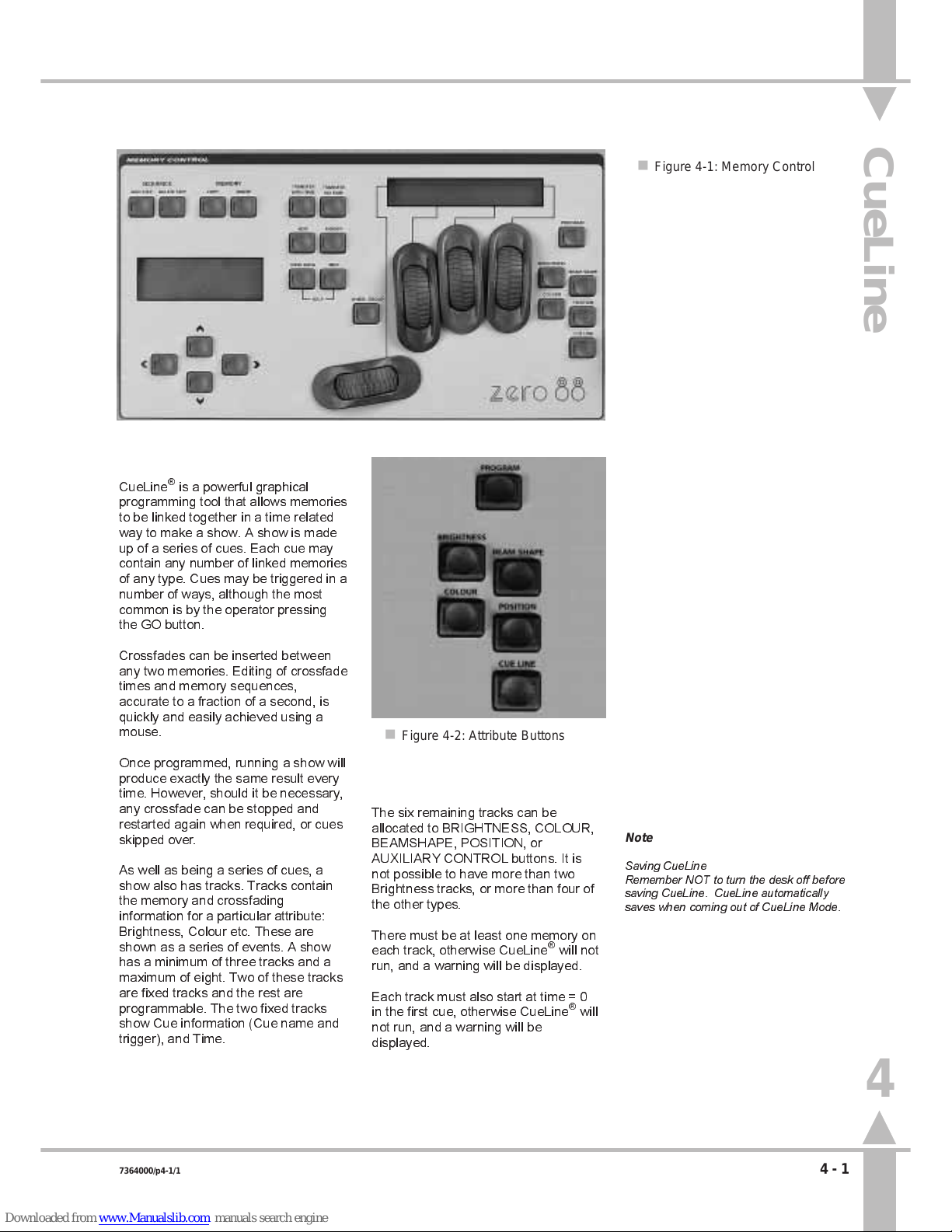
CueLine Introduction
What is CueLine®?
CueLine®is a powerful graphical
programming tool that allows memories
to be linked together in a time related
way to make a show. A show is made
up of a series of cues. Each cue may
contain any number of linked memories
of any type. Cues may be triggered in a
number of ways, although the most
common is by the operator pressing
the GO button.
Crossfades can be inserted between
any two memories. Editing of crossfade
times and memory sequences,
accurate to a fraction of a second, is
quickly and easily achieved using a
mouse.
Once programmed, running a show will
produce exactly the same result every
time. However, should it be necessary,
any crossfade can be stopped and
restarted again when required, or cues
skipped over.
As well as being a series of cues, a
show also has tracks. Tracks contain
the memory and crossfading
information for a particular attribute:
Brightness, Colour etc. These are
shown as a series of events. A show
has a minimum of three tracks and a
maximum of eight. Two of these tracks
are fixed tracks and the rest are
programmable. The two fixed tracks
show Cue information (Cue name and
trigger), and Time.
/p4-1/1
The six remaining tracks can be
allocated to BRIGHTNESS, COLOUR,
BEAMSHAPE, POSITION, or
AUXILIARY CONTROL buttons. It is
not possible to have more than two
Brightness tracks, or more than four of
the other types.
There must be at least one memory on
each track, otherwise CueLine
®
will not
run, and a warning will be displayed.
Each track must also start at time = 0
in the first cue, otherwise CueLine
®
will
not run, and a warning will be
displayed.
Note
Saving CueLine
Remember NOT to turn the desk off before
saving CueLine. CueLine automatically
saves when coming out of CueLine Mode.
n Figure 4-1: Memory Control
n Figure 4-2: Attribute Buttons
CueLine
4
7364000/p4-1/1 4 - 1
Page 59

CueLine Overview
The
CueLine
screen on the monitor is
split into a number of sections, as
follows: (see Figure 4-3)
l Menu Bar (PROGRAM mode only)
Common to all PROGRAM mode
screens and shows which section is
currently active.
l Toolbar (PROGRAM mode only)
Contains buttons that are selected
using the mouse, which define the
mouse action when clicked in the event
and track name areas of the screen.
l Track Name Area
Shows those tracks currently being
used and what memory type they
contain.
Cue information and time tracks are
always present.
l Zoom Buttons
Allow the operator to zoom in and out,
to see more details.
l Scroll Bar
After zooming in, this is used to move
to view a different section of the show.
l Event Area
The area where actions and memories
are shown and edited.
l THE CueLine (RUN mode only)
A vertical red line across the event
area of the screen. As an event passes
THE CueLine
, the event is triggered.
l Info Bar (PROGRAM mode only)
Provides hints on those actions
available.
/p4-2/1
Toolbar Buttons
Edit
This allows the timing of
memories, blackouts and
crossfades to be modified in
the event area.
Insert Memory/Cue
Another cue or memory may
be inserted in the event area
by placing the cursor in a track
and clicking. Clicking in the cue
track inserts a cue; clicking in another
track inserts the appropriate type of
memory. Cues and memories are
initially inserted as boxes with a default
duration which may be subsequently
edited if necessary. Memories may be
added anywhere in the sequence along
the track. Clicking in the second half of
a memory box will add a memory after
that memory; clicking in the first half of
a memory box will add another
memory before that memory.
Insert Blackout
Allows a blackout to be
inserted in a Brightness track,
thus eliminating the need to
program blackout memories.
Insert Fade/Transition
A crossfade may be inserted
by clicking in the Brightness
track between two memories,
e.g. fade Memory 1 out, whilst
Memory 2 fades up (fades are inserted
with default times for subsequent
editing).
Clicking in any other track will insert a
transition time (with default times).
Remove
With this button active, any
crossfade, memory or cue may
be removed from CueLine by
clicking on it. This does not
delete the memory, but removes that
particular occurrence of the memory
from CueLine.
Menu Bar
Toolbar
Zoom Buttons
Info Bar
Track Name Area
Event Area
THE CueLine
Edit Info
(Run Mode only)
Scroll Bar
Selected Tool
n Figure 4-3: CueLine screen
4
CueLine Introduction
4 - 2 7364000/p4-2/1
Page 60

CueLine Programming
Setting up to Programming CueLine
To use CueLine, Sirius 250/500 must
have a monitor and mouse connected,
and preferably a keyboard.
It is necessary to have already
programmed all the required
Brightness, Colour, Beamshape and
Position memories before starting to
program CueLine.
1 Turn the Key Switch to PROGRAM
mode.
2 Press the CUELINE button or use
the arrow keys to select CueLine.
3 On first entering the
CueLine
screen in PROGRAM mode, or
after a Super User Clear All, or
Clear CueLine, the CueLine
system needs to be set up.
/p4-3/1
Defining Tracks
1 When CueLine is entered for the
first time, press the } key to open
the
Edit Track Types
window, with
the active bar on Track 1. (See
Figure 4-4.)
2 Click on the track description box
to scroll through the list of track
types available, which are:
Not Defined
Brightness A
Colour A
Beamshape A
Position A
Auxiliary 1
Auxiliary 2
Auxiliary 3
Auxiliary 4
Auxiliary 5
Auxiliary 6
Auxiliary 7
Auxiliary 8
(only 4 Auxiliary on Sirius 250)
Once a track type has been
defined, that track can only control
the associated memory type (or
AUXILIARY CONTROL button).
3 Select Brightness A for Track 1.
4 Click on Track 2. Brightness B
appears.
5 Continue down the list defining
those tracks required to complete
the show, and click on
Confirm
.
Redefining a Track
1 If a track needs to be redefined
once cues and memories have
been inserted select the
Insert
Memory/Cue
button.
2 Click in the track name area to
bring up the
Edit Track Types
window.
3 Click on the appropriate track
description box to change type. If
necessary, use
Not defined
to
remove the track from use.
NOTE
Track Notes
A maximum of two Brightness tracks are
available (A and B), and a maximum of six
tracks for Colour, Beamshape and Position
(A, B, C, D, E and F).
Redefining a track removes all inserted
memories and crossfades.
Some tracks may be left not defined.
If no memories are inserted in a defined
track, CueLine will not run, therefore only
define those tracks to be used.
The [ and ] keys can also be used to cycle
through the track types available.
n Figure 4-4: Edit Track Types
4
CueLine Programming
7364000/p4-3/1 4 - 3
Page 61

Setting Up Cues
1 On confirming track descriptions
for the first time, the
New Cue
window opens (see Figure 4-5).
Click on the trigger window. The
choice is
Go button
, or
Automatic
. Click on
Go button
.
2 Click in the
Info
line and type in the
cue information.
3 Click on
Insert
. The first cue is
displayed on the screen.
Adding Cues
1 Select the
Insert Memory/Cue
button.
2 To add further cues, click in the
cue track on the dark gray
background to the right of the last
cue.
3 To add a new cue between
existing ones, click near the join of
the two cues. Clicking on the
left-hand side of a cue inserts a
cue before it, and on the right-hand
side inserts a cue after it.
/p4-4/1
Once the CueLine tracks have been
defined and at least one cue inserted,
memories can be added. This is
demonstrated next, but first insert three
more cues following the instructions in
the section on Adding Cues above.
Removing a Cue
WARNING
Removing a cue removes all memories
and events from the associated tracks.
1 Select the
Remove
button and
click on the cue. A warning is
displayed. (See Figure 4-6).
2 Press the PROGRAM button to
delete a cue, or the[ key to cancel.
n Figure 4-5: New Cue window
n Figure 4-6: Remove Cue window
4
CueLine Programming
4 - 4 7364000/p4-4/1
Page 62

Inserting Memories
1 Select the
Insert Memory/Cue
buttons.
2 Click on the Brightness track
(Track 1) in Cue 1.
3 Select a memory to add onto the
track from the list in the
Select
Brightness Memory
window, and
click on
Insert
.
The memory is added to the
Brightness track for a default
duration of 5 seconds. The time
track shows real time in seconds.
4 Now add a second memory in
Cue 3 (Memory 2). (Click on the
brightness track in Cue 3 and
select a memory.) See Figure 4-7.
The first and second memories are
joined by a gray bar, indicating that
the output from the first memory
will be held, even through cues,
until the second memory is
triggered.
THE CueLine
will
trigger a memory, and its output is
then held until another
memory/event is triggered.
5 Extra memories can now be added
in the same cue, or in different
cues. To add an extra memory
before an existing memory, click
on the left-hand side, or on the
right-hand side for a memory after.
Removing a Memory
1 Select the
Remove
button and
click on the memory.
The memory is removed without
any warning being displayed.
NOTE
Turning Off
To turn off a Brightness Track (stop all
brightness output), insert a blackout.
/p4-5/1
n Figure 4-7: Inserting Brightness Memories
n Figure 4-8: Selected Brightness Memory
n Figure 4-9: Selected Cross Fade
4
CueLine Programming
7364000/p4-5/1 4 - 5
Page 63

Inserting Fades/Transitions
1 To insert a fade between
memories, select the
Insert
Fade/Transition
button.
2 Click on the left-hand side of a
memory to add a fade/transition
before the memory, and on the
right-hand side for one after.
Crossfades with a default time of
5 seconds are added to the
Brightness track (i.e. fading the
current memory down in
5 seconds, whilst fading the next
memory to full in the 5 seconds).
Simple transition fades are added
to any other track (i.e. going from
the current memory to the next
memory in 5 seconds).
Editing CueLine Memory Dwell
Times
Once a memory has been inserted into
a cue, its default duration and start
time can be changed.
1 Select the
Edit
button.
2 Click on the memory to be edited.
A red border appears. See
Figure 4-8.
3 To change the duration of the
memory, click and drag the small
red square in the border.
To alter the memorys start time
without affecting the duration,
whilst maintaining the same
running order, click inside the
memory (but not on the small red
square), and drag the whole
memory.
/p4-6/1
Editing Fades
1 Select the
Edit
button.
2 Click on the fade to be edited. For
a brightness crossfade, a red
border appears with five red
squares, each of which may be
dragged using the mouse - See
Figure 4-9.
The fade in and out attacks can
be changed to slow or fast, And a
blackout between if required. The
fade up and down times are
indicated during editing in the
bottom corner.
Transition fades only have one red
square, therefore only their
duration can be changed.
A fade can also be moved relative
to other events by clicking inside
the fade (but not on a small red
square) and dragging the whole
fade.
A fade added before the first
memory on a Brightness track is a
fade up. A fade added between a
memory and a blackout is a fade
down or fade up (whichever is
appropriate).
Inserting a Blackout
Blackouts can only be added to
Brightness tracks.
1 To insert a blackout between
memories, select the
Insert
Blackout
button.
2 Click on the left-hand side of a
memory to insert a blackout before
the memory, and on the right-hand
side for one after.
Editing Blackouts
1 Select the
Edit
button.
2 Click on the blackout to be edited.
A red border appears.
3 Click on the small red square and
drag the duration of the blackout to
the desired length. Or to move the
blackout relative to other events,
click within the border, and drag
the whole blackout.
NOTE
Canceling an Option
Cancel is always available alongside the
Insert and Confirm options.
Mouse Use
Click on always refers to a single click on
the left-hand mouse button.
Info Bar
This contains hints on other ways of
completing an operation using the arrow
keys.
4
CueLine Programming
4 - 6 7364000/p4-6/1
Page 64

Auxiliary Track
Auxiliary Track
CueLine can also action the front panel
AUXILIARY CONTROL buttons. A
track must be inserted for each button
to be controlled.
Once that has been done, the button
on the front panel automatically
becomes a momentary button,
irrespective of its programming.
1 Select
Insert Memory/Cue
button.
2 Click in the appropriate Auxiliary
track. The
Select Auxiliary Memory
window opens (see Figure4 -10 ).
3 Select Auxiliary off and click on
Insert
(see Figure 4-10.) The track
now has a default off state of
5 seconds.
Adding an On State
1 Select
Insert Memory/Cue
button,
and click on the appropriate
Auxiliary track. The
Select
Auxiliary Memory
window opens.
Select Auxiliary on and click on
Insert
.
A 5 second on state appears, the
timing of which can be adjusted.
Changing the Default Time
1 Select the
Edit
button.
2 To change a states duration, click
in the state and click and drag the
small red square in the border.
To alter the start time of the state
without affecting the duration,
whilst maintaining the same
running order, click inside the state
(but not on the small red square),
and drag the whole square.
/p4-7/1
NOTE
In the example shown in Figure 4-11 when
Memory 3 changes to Memory 2, the
AUXILIARY CONTROL button will stay on,
as the on was the last event.
For the Auxiliary to be on for a fixed time,
add an off state as in Figure 4-12.
n Figure 4-10: Select Auxiliary Memory Window
n Figure 4-11: Example 'Auxiliary on' for ever
n Figure 4-12: Example 'Auxiliary on' for 9 seconds
4
Auxiliary Track
7364000/p4-7/1 4 - 7
Page 65

Saving and Running CueLine
Saving CueLine Programs
Programmed information is
automatically saved when moving out
of CueLine. DO NOT turn the desk off
before CueLine is saved otherwise
data may be lost
/p4-8/1
Why Multiple Tracks?
A track holds a sequential list of events.
For example, a track may contain the
following:
Start
Blackout for 5 seconds.
Snap to the first memory for
10 seconds.
Fade to blackout in 3 seconds.
Blackout for 2 seconds.
Fade the second memory in over
3 seconds.
Hold the second memory for 5 seconds.
Fade to blackout in 4 seconds.
Figure 4-13 shows how this is
displayed.
It is apparent from Figure 4-13 that
only one action can occur at a time
Therefore if 5 seconds into the first
memory, the third memory needs to be
added to the output of the first memory
(for 3 seconds), the problem posed can
be resolved in two ways. Either create
a fourth memory, which is a
combination of the first and third
memories, and reprogram CueLine as
shown in Figure 4-14, or use two tracks
as shown in Figure 4-15.
But remember that although extra
tracks can be defined after CueLine
has been programmed, changing the
definition of a track will remove all
memories from that track.
n Figure 4-13: Original Track
n Figure 4-14: Original with extra memory
n Figure 4-15: Using Two Tracks
4
Saving and Running CueLine
4 - 8 7364000/p4-8/1
Page 66

Clearing CueLine
Accessing Super User
Press the [ and ] keys together,
whilst simultaneously turning the Key
Switch to PROGRAM mode.
The following options are available:
Clear Memories
Recovery
Language SetUp
Date & Time
Use the { and } keys to select the
option.
Once selected, use the ] key either to
enter the option or to change it.
To exit Super User turn the keyswitch
out of Program Mode.
MONITOR NOTES
:
Software Versions
The software versions are
continuously shown and therefore
there is no option to select.
/p4-9/1
Resetting CueLine
The
CLEAR MEMORIES
feature,
allows the resetting of all memories or
one type of memory to factory defaults.
1 Use the { and } keys to Select
CLEAR MEMORIES
Super User:
CLEAR MEMORIES ]
Press ] to select
or } for next Option
2 Press the ] key to enter
Clear
Memory
. The Memory Display
shows:
Clear Memories
BRIGHTNESS ONLY {}
Press ] to Clear
Or [ to Abort
3 Use the { and } keys to select
CueLine
from the following
options:
Brightness only
Colour only
Beamshape only
Position only
CueLine
Brightness Submasters
Focus Submasters
Clear All Memories
4 Once selected, press the ] key to
clear.
The Memory Display shows:
**WARNING**
CUELINE MEMORIES
Press Prog to Clear
Or [ to Abort
5 Press the PROGRAM button to
clear or the [ key to abort the
operation.
WARNING
Clearing Memories
Care must be exercised as this
operation clears all memories of the
type selected.
n Figure 4-16: Clearing Memories
4
Clearing CueLine
7364000/p4-9/1 4 - 9
Page 67

/p4-10/1
Page 68

Setting Up the Desk
Planning
It is virtually impossible to busk a
show with moving lights in the same
way that can be done with conventional
luminaires - they are just too
complicated. Planning is essential.
Busking it with moving lights means
selecting from preprogrammed effects
to create something, rather than
making it all up in an impromptu
fashion.
Any show has to be designed to create
the lighting effects required. Work out
what fixtures, intelligent or generic, are
required, where they have to be
positioned in the rig, and how they are
to be grouped. This can be entirely to
suit the operator - the desk does not
care. What is important is how the
operator best likes to work.
Some fixtures have technical
limitations, for example, the start
address may have a specific address
or range of addresses, rather than
being able to be patched to any of the
available 512 channels. Some
dimmers have channels grouped,
rather than patched individually.
/p5-1/3
Therefore work out what the technical
limitations of the equipment are in
terms of control. All the dimmers
usually have to be grouped together as
they have to be addressed
consecutively, as a block. Some
fixtures only work on particular DMX
addresses. Allocate DMX addresses to
make sure there are no conflicts.
HINT
Make it logical in some way; group fixtures
either by type or by position within the rig, or
both.
The desk can also deal with composite
fixtures, where one fixture consists of
two separate parts and requires two
DMX addresses, e.g. a Par Can and a
scroller, VL5s - head and dimmer.
Duplicate fixtures are also easily
accommodated. This is where multiple
fixtures on multiple DMX addresses are
controlled from one desk channel, and
is useful for cyc lights and light
curtains, etc.
Optimise cable runs, particularly
control cables. Check the DMX
loading. Ensure that there are enough
DMX splitters, isolators and terminators
to hand. Set up fixture switches, etc.,
whilst they are still on the ground.
n Figure 5-1: Setting up the Desk
Setting Up the Desk
5
7364000/p5-1/3 5 - 1
Page 69

Internal Memory Structure
During the course of normal operation,
there is no need for the operator to be
aware of the different types of memory
and data in the desk. Nor does
anything need to be done to protect
data, apart from the operator making
normal backups to floppy disk as a
precaution against the desk being
stolen, for example.
However, for information, there follows
an overview of how the data is handled
and stored by the desk.
The desk holds several types of data:
desk operating system software, fixture
data files (Zero 88 fixture and user
fixture files), desk set-up data, lighting
data (memories) and CueLine data.
The above types of data are stored in
four areas: volatile dynamic RAM,
battery backed static RAM, flash RAM
and floppy disk.
A floppy disk is only used to back up
existing data or to introduce new data
to the desk.
Volatile dynamic RAM is only used by
the desk operating system to speed up
the desk operation, not to store lighting
data.
Battery backed static RAM is very
quick to write to and read back from,
but it is not large.
Flash RAM is a very safe electronic
medium for storing data, with very little
chance of any data that is written to it
being lost. However, although it is
quick to read from, it has the
disadvantage of being fairly slow to
write to.
All desk operating software and fixture
data files are held in flash RAM. Desk
set-up data comprises the current
show name, the fixture data files for
those fixture types currently used, the
allocation of fixtures to desk channels
and DMX start address, and other
information, and is also stored in flash
RAM. Memories are stored initially in
battery backed static RAM. If a show is
large enough, it is moved to flash RAM.
Further memories programmed are
then periodically updated to flash RAM
automatically.
When the show is saved to floppy disk,
all desk set-up and lighting data is
saved, together with the fixture data
files used in the show.
If the desk is in an installation where
the rig does not change very much, but
many different shows are performed, it
is advisable to create a show called
Basic Rig with all fixtures and start
addresses allocated and a few basic
memories recorded, and to save it to a
floppy disk. This can then be reloaded
before creating a new show both to
allow rig testing and to provide a
known starting point.
Controls
l WHEELS
Used to adjust fixture parameter levels.
l WHEEL DISPLAY
Guides the operator on which wheel to
use for which parameter.
l PROGRAM BUTTON
Commits the current settings to
electronic memory.
l MEMORY DISPLAY
Guides the operator step by step
through the menus.
l ARROW KEYS
Use to scroll through the menus.
Shown as []{} keys throughout the
manual. If an external keyboard is
used, the cursor keys have the same
function.
l FLASH FUNCTION BUTTON
Modifies the function of the channel
flash buttons, enabling text entry and
fixture selection, as indicated by the
adjacent light. When setting up the
desk, the FLASH and SOLO functions
are disabled.
l CHANNEL FLASH BUTTONS
Have two functions in PROGRAM
mode: selecting fixtures; entering text.
/p5-2/3
l SHIFT BUTTON
Accesses the second row of text
characters on the channel flash buttons
and accessing Fixture 48 to 96 (25 to
48) in Wide Mode.
l AUXILIARY (AUX CONTROL)
BUTTONS
Can be programmed to
activate/deactivate predefined DMX
channels.
Navigating SetUp
The SetUp section of the desk is split
into six areas, as follows:
FILES
Controls saving of data and loading to
floppy disk.
ILLUMINATION
Allows the setting of litlite levels, desk
light (LED) brightness, LCD backlight
brightness and contrast.
DESK SETUP
Sets up the desk default values and
assigns fixtures to channels and DMX
start addresses.
FIXTURE SETUP
Allows the operator to create or modify
fixture files.
STAGE SETUP
(Not yet implemented.)
FIXTURE CONTROL
(Not yet implemented.)
Allows remote lamp on/lamp off and
reset for intelligent fixtures, assuming
the fixture has those functions.
5
Setting Up the Desk
5 - 2 7364000/p5-2/3
Page 70

Setup: Files
Selecting SetUp Options
1 Turn the Key Switch to PROGRAM
mode.
2 Use the [ and ] keys to select
Set-Up
.
3 Press the } key.
Use the [ and ] keys to select an
option from the list below.
Files
Illumination
Desk SetUp
Fixture SetUp
Stage SetUp
Fixture Control
4 Once selected press the } key.
Saving a Show
1 Press the } key. The Memory
Display shows:
Set-Up
FILES []
Select Option &
Press }
2 Press the } key the Memory
Display shows.
Files
Save Show to Floppy
Press ] to Select or
} for More
3 Press the } key
4 The first line displays the
previously entered
Show Name
.
Save: YOUR SHOWNAME
FILE:
Name & Press Program
Press } to Abort
Enter a file name which must be a
maximum of 8 characters with no
spaces, using the channel flash
buttons, or using the external
keyboard.
5 Insert a DOS formatted 3.5 1.44
MB floppy disk and press the
PROGRAM button. If there is
another show with the same file
name already on the disk, a
warning appears asking if the file
should be overwritten (where
available).
/p5-3/3
6 Press the PROGRAM button again
to confirm, or any other key to
abort. Modify the file name if
required. The show is now saved
to disk, during save a message
appears on the Display.
7 When completed the Memory
Display shows:
Files
Save Show to Floppy
Press ] to Select or
} for More
8 Press the } key to move to
Load
Show
.
Loading a Show
1 Move to
Load Show
. The Memory
Display shows:
Files
LOAD SHOW FRM FLOPPY
Press ] to Select or
} for More
2 Insert a floppy disk containing
previously saved shows into the
disk drive.
3 Press the ] key to open the
Load
Show
dialogue box, there may be
a short delay while the disk is read.
Shows to Load {}
Show Name
Press Prog to Load
or [ to Abort
The first show name is displayed in
the Memory Display use the
{ and} keys to select a show.
4 Press the PROGRAM button to
load the show.
If the desk is empty, the show
loads immediately. If there is a
show currently in the desk, a
warning appears asking for
confirmation before overwriting the
existing show (where available).
5 Press the PROGRAM button again
to confirm, or the [ key to return to
Load Show.
6 Press the } key to move to
Save
Operator Fixture Data
NOTE
HINT
Backups
Follow the safe option and make two copies
of all-important shows on separate disks.
Show Disk Compatibility
A show created and saved on a Sirius 250
can be loaded into a Sirius 500. A show
created on a 500 can NOT be loaded on to
a Sirius 250.
Disk Errors
If the desk encounters any disk error while
reading from a floppy disk, the show held on
internal memory will be rebuilt and checked
to ensure that it is not corrupt.
Date and Time
When the show is saved to a floppy disk, the
current time and date are saved to disk.
Monitor Note
:
Load Shows
When Loading Shows from Floppy
the monitor displays a list of available
shows to choose from..
5
Setup: Files
7364000/p5-3/3 5 - 3
Page 71

Saving Operator Fixture Data
1 The next option is
Save User
Fixture Data
. The ] key opens the
Save User Fixture Data
dialogue
box. The
Save User Fixture Data
window appears. Enter a file name
using a maximum of eight
characters (any combination of
letters or numbers can be used).
2 Ensure that a formatted disk is in
the floppy drive. Press the
PROGRAM button to continue, or
the } key to abort if required.
All fixture data files created by the
operator are saved to the floppy
disk in a single file,
Loading Operator Fixture Data
1 The next option is
Load User
Fixture Data
. Ensure that a
formatted disk is in the floppy drive
and press the ] key to open the
dialogue box. After a short delay a
list of the operator fixture data files
on the disk is displayed.
2 Use the { and } keys to select
which file to load.
3 Press the PROGRAM button to
load the new file, or [ key to abort.
Copying a Disk
Not yet implemented.
1 The next option is
Copy
disk.
Press the ] key to open the
Copy
dialogue box. The box contains a
list of files on the disk.
All Files
is
an option (default).
2 Use { and } keys to select which
file(s) to copy.
3 Press the PROGRAM button. The
desk reads the file and requests
the operator to remove the read
(source) disk and insert another
(destination) disk on which to copy
the file(s).
4 Two option boxes appear:
Copy
and
Cancel.Copy
is highlighted.
Press the PROGRAM button to
copy the file data to the disk. The
desk then checks data integrity
and puts up a message if correct.
The box closes automatically on
successful completion after a short
delay.
5 Use the ] key to select
Cancel
if
required.
.
/p5-4/3
Printing, Saving in ASCII Format,
and Loading in ASCII Format
Print,Save in ASCII Format
, and
Load
in ASCII Format
not yet implemented.
Formatting the Disk
Not yet implemented.
1 The final choice in this section is
Format
disk. Press the ] key to
open the dialogue box with
instructions for formatting the disk.
The box closes on successful
completion.
5
Setup: Files
5 - 4 7364000/p5-4/3
Page 72

SetUp: Illumination
SetUp: Illumination
The next stage is to adjust the setting
of the desk lamp brightness, LED
Brightness, LCD backlight brightness
and contrast.
Move to
Set-Up: Illumination
,as
described in the section on Selecting
Set-Up Options on page 5-3, the
Memory display shows
Set-Up
ILLUMINATION []
Select Option &
Press }
1 Use the } key to move to
Desk
Lamp Brightness
. The index finger
wheel now controls the Brightness
of the desk lamps. The level of the
lamps is shown in the window.
2 Use the } key to move to
LED
Brightness
. The index finger wheel
now controls the Brightness of the
lights (LEDS) on the desk. The
level of the lights is shown in the
window (NOT Output Lights).
3 Use the } key to move to
Memory
LCD
. The index finger wheel
controls the Brightness of the
backlighting on the Memory
Display, and the middle finger
wheel controls the contrast of the
LCD. These should be adjusted to
give the clearest image in the
Display in the prevailing conditions.
4 Use the } key to move to
Wheel
LCD
(Wheel Display). These
should be adjusted in the same
way as for the Memory Display.
5 Press the } key once to return to
Desk Lamp Brightness.
6 Press the { key to exit to
Set-Up.
Set-Up
ILLUMINATION []
Select Option &
Press }
/p5-5/3
n Figure 5-2: Set-Up: Illumination screen
n Figure 5-3: Control Wheel Layout
Thumb Index Middle Third
finger finger finger
5
SetUp: Illumination
7364000/p5-5/3 5 - 5
Page 73

SetUp: Desk SetUp
SetUp: Desk Set-Up
Having planned the Rig, the next stage
is to set up the desk with fixtures as
required. Most of this can be done
without a monitor, however, it is much
easier with one.
1 Press the } key to enter
Desk
Set-Up.
Set Up: Show Name
Your Show Name Here
Enter Name & Press }
To Cont { to Exit
Enter the show name using the
channel flash buttons, or using the
external keyboard.
2 Press the } key.
Set Up: Wide/Normal
Set to: Normal
Use [] to Select
Normal/Wide. Press }
Use the [ and ] keys to select
NormalorWide
mode.
3 Press the } key.
Set Up: Warning
Set to: Beep off
Use [] to Select
Beep On/Off & Press }
Use the [ and ] keys to select
whether or not the desk gives an
audible warning if the operator
attempts to do something
inappropriate.
4 Press the } key.
Set-Up: Remote Go
Set to: ENABLED
Use [] to Select
And Press }
Use the [] keys to select whether
or not the desk responds to the
GO button remoted via the MIDI
connectors see Figure 5-5 for
wiring. The Remote Go will only
accept approx one press per
second.
/p5-6/3
5 Press the } key.
Set-up: Brightness
SHOW AS DMX VALUE []
Select DMX or %
Press } to Continue
Use the [ and ] keys to choose
between percentage (shown as
0-100) or DMX value (shown as
0-255).
6 Press the } key.
Set-up: Other
SHOW AS DMX VALUE []
Select DMX or %
Press } to Continue
Use the [ and ] keys to choose
between percentage (shown as
0-100) or DMX value (shown as
0-255).
7 Press the } key to move through
the following areas. (The number
in brackets cites the relevant page
for the section.)
Assign Fixtures
(5-7)
Brightness Defaults
(5-17)
Colour Defaults
(5-18)
Beamshape Defaults
(5-18)
Position Defaults
(5-18)
Movement Effects
(3-17)
Once one of the above has been
selected, press the ] key to move
to the section. On entering the
section, follow the instructions on
the relevant page.
Use the { key to move up the list.
NOTE
WIDE Mode
If WIDE mode is enabled, the extra fixtures
can only be used to control the Brightness of
single channel conventional luminaires
(generics).
Sirius 250 fixtures 24 - 48 generic
conventionals only, and Sirius 500 fixtures
49 - 96 generic conventionals.
n Figure 5-4: Desk Set-Up menu
Midi foot switch wiring
midi in midi out
1
2
3
4
5
1
2
3
4
5
normally open
switch
n Figure 5-5 Midi Remote Go
5
SetUp: Desk SetUp
5 - 6 7364000/p5-6/3
Page 74

Assigning Fixtures
1 Move down to
Assign Fixtures
to
View and edit fixture, channel and
DMX assignments .
2 Press the ] key to open a large
dialogue box with several function
selection windows. The
View
Current Set-Up
window is
highlighted active.
The options available are:
Clear Set-Up
Load Default Set-Up
Clear DMX Patch
View Current Set-Up
Modify Set-Up
Auto Patch Fixtures
Set DMX & Controls
Auxiliary Control
Use the { and } keys to move
around the list, and press the ]
key to make a selection active.
Viewing the Current Set-Up
1 Use the { and } keys to move to
View Current Set-Up
(if not already
selected), and press the ] key.
The
Fixture Assignment
window is
displayed, showing what type of
fixture has been allocated to which
desk channel, and its DMX start
address if assigned (NAmeans
not assigned). See Figure 5-6:
/p5-7/3
2 Use the { and } keys to scroll up
and down the list, or the channel
flash buttons to jump to a fixture.
The data is shown in the Memory
Display and on the monitor. The
Memory Display shows:
Current Fix 48 {}
Cyberlight Mode 1
DMX Address: 100
[ to Return
The currently selected
channel/fixture is indicated by a
red light in the channel flash button.
3 Press the [ key to return to the
View Current Set-Up
window.
Clear DMX Patch
WARNING
This option can change the whole
desk set-up. Read instructions
before use.
The
Clear DMX Patch
option removes
all the start addresses from any fixture
already assigned. The start addresses
are replaced with NA (not assigned).
1 Press the { key.
Assign Fixtures
CLEAR DMX PATCH
Press ] to Clear
Or } to Modify
2 To continue press the ] key.
Press Program to
Clear DMX Patch
Or [ to Abort
Either press the [ key to abort, or
the PROGRAM button to clear the
DMX patch.
After pressing either the [ key or
the PROGRAM button, the screen
returns to the
Clear DMX Patch
display.
Returning to
View Current Set-Up
would show the operator the same
list of fixtures with all DMX
addresses set toNA.
n Figure 5-6: Viewing Current
5
SetUp: Desk SetUp
7364000/p5-7/3 5 - 7
Page 75

Load Default Set-Up
WARNING
This option can change the whole
desk set-up. Read instructions
before use.
The
Load Default Set-Up
option
replaces all existing fixtures with a
generic (single Brightness channel
fixture), and patches Fixture 1 to DMX
Channel 1, Fixture 2 to DMX Channel
2, Fixture 3 to DMX Channel 3, etc.,
up to and including the last fixture. This
is the default setting when the desk is
new.
1 Press the { key.
Assign Fixtures
LOAD DEFAULT SET-UP
Press ] to Load
Or } to Modify
2 Press the ] key to enter
Load
Default Set-Up
. A warning is
displayed:
*This operation may*
*Damage Memory Data*
Press Program toLoad or [ to Abort
See Figure 5-7.
/p5-8/3
3 Press PROGRAM to continue with
Load Default Set-Up
, or the [ key
to abort. Either option returns to
the
Load Default Setup
window.
The result can be seen by Viewing
current setup.
(see section on page 5-7.)
Clear Set-Up
WARNING
This option can change the whole
desk set-up. Read instructions
before use.
The
Clear Set-Up
option changes all
fixtures and all start addresses to Not
Assigned.
1 Press the { key.
Assign Fixtures
CLEAR SET-UP
Press ] to Clear
Or } to Abort
2 Press the ] key to enter
Clear
setup
.
*This operation may*
*Damage Memory Data*
Press Program to
Clear or [ to Abort
Press PROGRAM to confirm the
request to clear, or the [ key to
abort. Either option returns to the
Clear Setup
window.
The result can be seen by Viewing
current setup.
(see section on page 5-7.)
HINTS
If the desk is about to be used with a new
complex, full rig, it is sometimes easier to
clear the set-up before starting.
If a new rig is substantially or wholly generic,
use Load Default Set-Up to make the whole
desk generic, and use Modify Set-Up to
modify individual fixtures.
NOTE
Default Set-Up
The default set-up is all channels set to
Brightness only (generic), the DMX channel
is set to the desk fixture number 1 to 1,
2 to 2, etc.
n Figure 5-7: Fixture Assignments
5
SetUp: Desk SetUp
5 - 8 7364000/p5-8/3
Page 76

Modifying the Set-Up
1 Move down to
Modify Set-Up
and
press the ] key. A warning
appears to the effect that memory
data may be lost, damaged or
become unusable if fixture data is
changed.
*THIS OPERATION MAY*
*DAMAGE MEMORY DATA*
Press ] to continue
or [ to abort
Press the [ key to abort or the]
key to continue. The
Fixture
Assignment
window is opened.
2 Press the channel flash buttons to
select all desk channels to be used
to control a particular type of
fixture. These are highlighted in
the list as the buttons are pressed.
The red light in the buttons also
come on.
3 Press the ] key to open a window
containing a list of fixture
manufacturers.
4 Use the { and } keys to select the
required manufacturer.
Mod Set-Up: Select {}
HIGH END SYSTEM
Press Program to
View Fixture Types
Once selected, press the
PROGRAM button or the ] key to
open a window showing the
available fixture types for that
manufacturer. (See Figure 5-8 for
monitor display.)
Mod Set-Up: Select {}
HIGH END SYSTEMS
Cyberlight Mode 3
Program to SAVE
Use the { and } keys to select the
required fixture type, and press the
PROGRAM button to assign the
fixture type to the desk channel(s).
The fixture type on the list changes
to the type just selected, and all
the DMX addresses change to
NA
(not assigned).
Modify Set-Up:
Select Fixture No
Press ] to Allocate
Or [ to Return
5 Repeat this process until all the
right fixtures have been allocated
to the right desk channels, and
press the [ key to return to the
Modify Set-Up
window.
/p5-9/3
NOTE
Unassiging Fixtures
Follow steps 1 to 3 opposite then select
<Clear> from the fixture manufactures list
and press Program. The selected desk
channels will be cleared and displayed as
Not Assigned in the Fixture Assignment
Window
n Figure 5-8: Fixture Type
5
SetUp: Desk SetUp
7364000/p5-9/3 5 - 9
Page 77
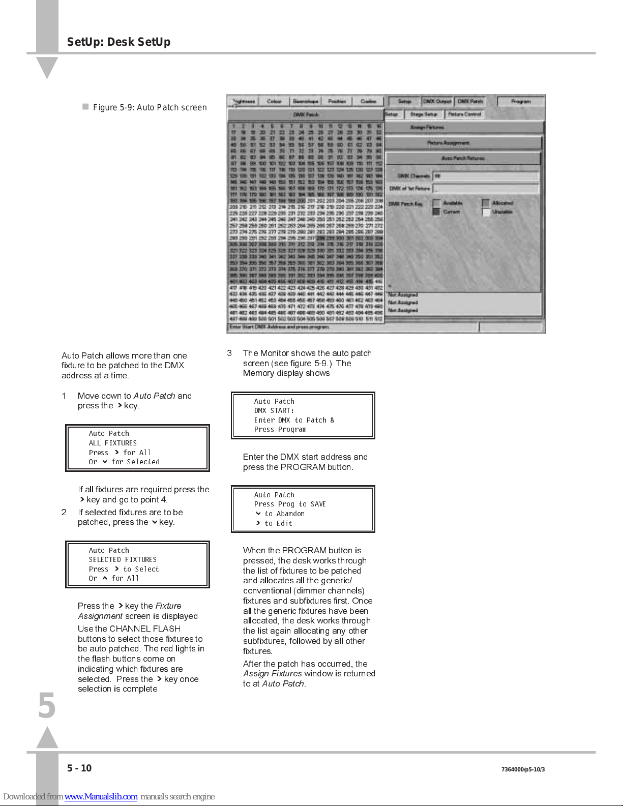
Auto Patch DMX
Auto Patch allows more than one
fixture to be patched to the DMX
address at a time.
1 Move down to
Auto Patch
and
press the ] key.
Auto Patch
ALL FIXTURES
Press ] for All
Or } for Selected
If all fixtures are required press the
] key and go to point 4.
2 If selected fixtures are to be
patched, press the } key.
Auto Patch
SELECTED FIXTURES
Press ] to Select
Or { for All
Press the ] key the
Fixture
Assignment
screen is displayed
Use the CHANNEL FLASH
buttons to select those fixtures to
be auto patched. The red lights in
the flash buttons come on
indicating which fixtures are
selected. Press the ] key once
selection is complete
/p5-10/3
3 The Monitor shows the auto patch
screen (see figure 5-9.) The
Memory display shows
Auto Patch
DMX START:
Enter DMX to Patch &
Press Program
Enter the DMX start address and
press the PROGRAM button.
Auto Patch
Press Prog to SAVE
} to Abandon
]toEdit
When the PROGRAM button is
pressed, the desk works through
the list of fixtures to be patched
and allocates all the generic/
conventional (dimmer channels)
fixtures and subfixtures first. Once
all the generic fixtures have been
allocated, the desk works through
the list again allocating any other
subfixtures, followed by all other
fixtures.
After the patch has occurred, the
Assign Fixtures
window is returned
to at
Auto Patch
.
n Figure 5-9: Auto Patch screen
5
SetUp: Desk SetUp
5 - 10 7364000/p5-10/3
Page 78

Setting the DMX Address and
Controls
1 Move down to
Set DMX and
Controls
. The Memory Display
shows:
Assign Fixtures
Set DMX & Controls
Press ] to setup DMX
or } for Auxiliary
Press the ] key to open the
Fixture Assignment
window again.
Desk channel 1
is highlighted.
2 Use the { and } keys or channel
flash buttons to select a fixture to
view the current fixture type and
DMX start address.
Set DMX: Fixt: 1 {}
Cyberlight Mode 1
DMX Address: 200
Press ] to assign
3 Press the ] key to modify the
current settings and set the DMX
address.
Set-Up Fix 1 DMX
Start Address = 200
Enter DMX Address
and Press Program
/p5-11/3
See Figure 5-10.
Enter the new DMX Start Address
using the channel flash buttons,or
the external keyboard. Any current
value will be overtyped
automatically.
Press Program to save the DMX
address.
If the DMX address entered cannot
be used or overlaps with that of
another fixture, a warning appears:
**ERROR WARNING**
DMX Address
DMX Channels Overlap
Press [ to Continue
4 Press the [ key and enter a Valid
DMX address and press Program.
Having successfully entered a
valid DMX address the Enter
Info
window is displayed
5 Enter a description using the
channel flash buttons or the
external keyboard.
6 Press the } key.
Set-Up Fix: 1
Use [ to Finish
} to Set Controls
] to Add Duplicates
7 Press the [ key to finish, the }
key to set the controls (see the
following section on Setting Fixture
Controls), or the ] key to add
duplicates (see the section on
Duplicates on page 5-13).
NOTE
DMX Address
If a DMX address is entered that causes a
conflict with another fixture, the desk warns
the operator. Either the one being worked
on can be changed, or the one conflicted
with de-allocated and a different DMX
address allocated to that fixture.
MONITOR NOTES
:
DMX Address
When setting the DMX address, a
map is shown giving the current
status of all the 512 DMX channels.
n Figure 5-10: Set DMX Address
5
SetUp: Desk SetUp
7364000/p5-11/3 5 - 11
Page 79

Setting Fixture Controls
See Figure 5-11 for monitor display.
Pan Reverse
1 This allows the control wheels to
work backwards so that if the
fixture is facing forwards in the rig,
the beam still moves to the left
when the control wheel is moved
to the left. The [ and ] keys
toggle between normal and
reverse operation.
2 Press the } key to move to
Tilt
Reverse
.
Tilt Reverse
3 This allows the control wheels to
work backwards so that if the
fixture is facing forwards in the rig,
the beam still moves upwards
when the control wheel is moved
upwards. The [ and ] keys toggle
between normal and reverse
operation.
4 Press the } key to move to
Pan
Tilt Swap
.
Pan Tilt Swap
5 This maintains normal operation,
even when the fixtures are
mounted on the sides of the rig.
The[ and] keys to toggles
between pan and tilt swapped and
normal operation.
/p5-12/3
6 Press the } key followed by the [
key to finish setting the controls
and return to:
Set-Up Fix: 1
Use [ to Finish
} to Set Controls
] to Add Duplicates
NOTE
Movement Effects
Swopping Pan & Tilt does not affect the
orientation of the movement effects.
n Figure 5-11: Setting Fixture
5
SetUp: Desk SetUp
5 - 12 7364000/p5-12/3
Page 80

Duplicates
It is possible to add duplicates to
fixtures and auxiliary controls.
Duplicate fixtures are one or more
occurrences of the original fixture
located at a different DMX start
address. Duplicate fixtures act in
exactly the same way as the original,
by outputting the same data on
different DMX addresses.
Adding Duplicate Fixtures
1 Move down to
Set DMX and
Controls
. The Memory Display
shows:
Assign Fixtures
Set DMX & Controls
Press ] to setup DMX
or } for Auxiliary
Press the ] key to open
Fixture
Assignment
window again.
Desk
channel 1
is highlighted.
2 Use the { and } keys or channel
flash buttons to select a fixture to
view the current fixture type and
DMX start address, see
Figure 5-12.
Set DMX: Fixt: 1 {}
Cyberlight Mode 1
DMX Address: 200
Press ] to assign
3 Press the ] key.
Set-Up Fix 1 DMX
Start Address = 200
Enter DMX Address
and Press Program
4 Press the } key twice.
Set-Up Fix: 1
Use [ to Finish
} to Set Controls
] to Add Duplicates
/p5-13/3
Press the ] key to add duplicates.
Duplicate Fixt 1
No. of Duplicates 0
Enter No Duplicates
and Press Program
See Figure 5-13 for monitor
display. Use the channel flash
buttons or the external keyboard to
enter the number of duplicates
required (for example 3).
5 Press the PROGRAM button.
Set-up Fix: 1 Pri Out
Mac 600 Mod DMX 20
Enter DMX Address
& Press Program
6 Press the PROGRAM button to
confirm the original fixtures DMX
channel.
The top line changes to Duplicate
1 of the fixture.
Set-up Fix: 1 Dup 1
Mac 600 Mod DMX _
Enter DMX Address
& Press Program
Enter the DMX address using the
channel flash buttons, or using the
external keyboard.
7 Press the PROGRAM button. If the
DMX address is accepted, the
Memory Display shows:
Set-up Fix: 1 Dup 1
Mac 600 Mod DMX _
Enter DMX Address
& Press Program
The top line changes to the next
duplicate of the fixture.
n Figure 5-12: Fixture Type and DMX Start address
5
SetUp: Desk SetUp
7364000/p5-13/3 5 - 13
Page 81

If the DMX address is not
accepted, a warning appears.
**ERROR WARNING**
DMX Address Already
Allocated
Press [ to Continue
Press the [ key to continue. The
Memory Display reverts to:
Set-up Fix: 1 Dup 1
Mac 600 Mod DMX _
Enter DMX Address
& Press Program
Enter the correct DMX address.
8 Enter the DMX address for the
second duplicate. Press the
PROGRAM button.
Continue entering DMX addresses
for any remaining duplicates of the
fixture.
9 When the PROGRAM button is
pressed for the last duplicate, the
Memory Display shows:
Finished Adding
Duplicates?
Press [ to Return
or { to Edit
Press the [ key to return to:
Set-Up Fix: 1
Use [ to Finish
} to Set Controls
] to Add Duplicates
10 Press the [ key to select another
fixture.
NOTE
Duplicates
Duplicates can be set up at the same time
as the primary instance of a fixture. The
instructions are detailed separately for ease
of reference.
MONITOR NOTES
:
Fixtures
A list of fixtures together with their
start addresses is shown on the
monitor.
:
Duplicates
Where duplicates have been defined
the Monitor displays show the DMX
address for the original and duplicate
fixtures.
/p5-14/3
Continuing After Setting the DMX
Address
1 When all fixtures have their DMX
addresses set up and their pan
and tilt controls the right way
round, press the [ key to return to
the
Assign Fixtures
menu.
2 Press the } key to move to
Auxiliary Control
.
n Figure 5-13: Duplicate Fixtures screen
5
SetUp: Desk SetUp
5 - 14 7364000/p5-14/3
Page 82

Setting the Auxiliary Controls
1 The final part of
Assig Fixtures
is
programming the auxiliary
controls. Move to
Auxiliary control
.
The Memory Display shows:
Assign Fixtures
AUXILIARY CONTROL
Press ] to Setup Aux
or Press [ to Return
2 Press the ] key to open the
Auxiliary Control
dialogue box.
Auxiliary Control
AUX CONTROL 1 []
Select Aux Control &
Press } to Continue
See Figure 5-14 for monitor
display. Use the [ and ] keys to
select the auxiliary control to be
programmed, or use the AUX
CONTROL buttons on the desk.
3 Press the } key to move to
Info
,
an optional text field to describe
what is being controlled.
Enter a description using the
channel flash buttons,or using the
external keyboard.
4 Press the } key.
Aux Control 1 Action
Set To: MOMENTARY
Set using [] and
Press } to Continue
Use the [ and ] keys to toggle
between
Momentary
and
Push
On/Push Off.
5 Press the } key.
Aux Control 1: On
On Level = 100%
Set Level on Wheel
Press } to Continue
The
On Value
is highlighted. The
default value when the AUX
CONTROL button is selected is
100%, or 255. If a different value is
required, use the index finger
wheel to set the new value.
6 Press the } key to highlight the
Off
Value
box, and adjust as
necessary. The default value for
off is 0%.
/p5-15/3
7 Press the } key twice.
Aux Cntrl 1 DMX
DMX Address 512
Enter Address and
Press Prog for More
Enter the DMX address of the
device to be controlled and press
the PROGRAM button.
8 Press the [ key to return to
Assign
Fixtures
.
5
n Figure 5-14: Adding Duplicates
SetUp: Desk SetUp
7364000/p5-15/3 5 - 15
Page 83

Adding Duplicate Auxiliary Controls
1 Follow points 1 to 6 from the
section on Setting the Auxiliary
Controls.
2 Press the } key once.
Aux Control 1:
Duplicates= 0
Enter No Duplicates
Press } to Continue
Enter the required number of
duplicates (maximum nine).
3 Press the } key once.
Aux Cntrl 1 DMX 500
Primary Output ]
Select Instance
Press } to Continue
Use the [ and ] keys to review
the settings of the Primary Output
and Duplicates.
Return to first duplicate using
the[ and ] keys.
4 Press the } key once.
Aux Cntrl 1 Dup: 1
DMX Address _
Enter Address and
Press Prog for More
Enter the DMX address using the
channel flash buttons, or using the
external keyboard.
5 Press the PROGRAM button to
confirm the above DMX address.
The top line of the Memory display
changes to the next Duplicate of
the
Auxiliary Control
.
Aux Cntrl 1 DMX 2
DMX Address _
Enter Address and
Press Prog for More
6 Enter the DMX address using the
channel flash buttons, or using the
external keyboard.
7 Press the PROGRAM button to
confirm the DMX address.
8 Repeat points 6 and 7 until all
instances have been programmed.
9 When the PROGRAM button is
pressed to confirm the last DMX
address, the Memory Display
shows:
Auxiliary Control
Finished
Press [ to Return
or } to Continue
10 Press the [ key twice to return to
the
Assign Fixtures
screen.
/p5-16/3
NOTE
Auxiliary Controls
Duplicate Auxiliary Controls can be set up at
the same time as the primary instance an
Auxiliary Control. The instructions are
detailed separately for ease of reference.
5
SetUp: Desk SetUp
5 - 16 7364000/p5-16/3
Page 84

Brightness Defaults
1 Move down to
Brightness Defaults
.
Set-Up:
BRIGHTNESS DEFAULTS
Press ] to Select or
} to Continue
2 Press the ] key to bring up the
Brightness Defaults
dialogue box,
see Figure 5-15.
Brightness Defaults
START EFFECTS @ 13
Set Level & Press }
To alter the
Start Effects @
level,
use the wheel indicated in the
Wheel Display to set the fader
level, at which point a chase effect
starts if that is the selected way of
starting it. The value is displayed in
either percentage or DMX value.
See the section on Start Stop
Options in Programming a
Brightness Memory Chase Using
4 Wheel Drive
®
, on page 3-26.
3 Press the } key. Use the wheel to
adjust the
Chase Speed
which is
shown in beats per minute. The
factory default is 60.
4 Press the } key. Use the wheel to
adjust the
Fade In Time
shown in
mins:secs:tenths.
5 Press the } key. Use the wheel to
Adjust the
Fade Out Time
in the
same way.
Fade times can also be entered via
the external keyboard. See Editing
Times on page 3-5.
6 Press the } key, followed by the [
key to return to
Brightness
Defaults
.
7 Press the } key to move to
Colour
Defaults.
NOTE
Times Entered via the Keyboard
415 Return = 415 seconds displayed as
06:55:0, i.e. 6 minutes 55 seconds.
6:55:0 is the same.
6.5 = 6.5 seconds = 00:06:5.
/p5-17/3
n Figure 5-15: Brightness Defaults screen
n Figure 5-16: Colour Defaults screen
5
SetUp: Desk SetUp
7364000/p5-17/3 5 - 17
Page 85

Colour Defaults
1 Move down to
Colour Defaults
.
Set-Up:
COLOUR DEFAULTS
Press ] to Select or
} to Continue
Press the ] key to bring up the
Colour Defaults
dialogue box, see
Figure 5-16.
2 Use the wheel indicated in the
Wheel Display to set the
Chase
Speed
. The factory default is 60
beats per minute.
3 Press the } key to move to
Transition Time
. This is the time
taken to move from one memory to
the next. The factory default is
0:05:0. Use the wheel to adjust
time if required.
Transition times can also be
entered via the external keyboard.
See Editing Times on page 3-5.
4 Press the } key, followed by the [
key to return to
Colour Defaults
.
5 Press the } key to move to
Beamshape Defaults.
/p5-18/3
Beamshape Defaults
1 Move down to
Beamshape
Defaults
. Press the ] key to bring
up the
Beamshape Defaults
dialogue box.
2 Use the wheel indicated in the
Wheel Display to set the
Chase
Speed
. The factory default is 60
beats per minute.
3 Press the } key to move to
Transition Time
. This is the time
taken to move from one memory to
the next. The factory default is
0:05:0. Use the wheel to adjust
time if required.
Transition times can also be
entered via the external keyboard.
See Editing Times on page 3-5.
4 Press the } key, followed by the [
key to return to
Beamshape
Defaults
.
5 Press the } key to move to
Position Defaults.
Position Defaults
1 Move down to
Position Defaults
.
Press the ] key to bring up the
Position Defaults
dialogue box.
2 Use the wheel indicated in the
Wheel Display to set the
Chase
Speed
. The factory default is 60
beats per minute.
3 Press the } key to move to
Transition Time
. This is the time
taken to move from one memory to
the next. The factory default is
0:05:0. Use the wheel to adjust
time if required.
Transition times can also be
entered via the external keyboard.
See Editing Times on page 3-5.
4 Press the } key, followed by the [
key to return to
Position Defaults
.
5 Press the } key to move to
Movement Effects.
NOTE
Times Entered via the Keyboard
415 Return = 415 seconds displayed as
06:55:0, i.e. 6 minutes 55 seconds.
6:55:0 is the same.
6.5 = 6.5 seconds = 00:06:5.
n Figure 5-17:
Warning shown when exiting Desk
Set-Up
5
SetUp: Desk SetUp
5 - 18 7364000/p5-18/3
Page 86

Movement Effects
The editing of
Movement Effects
is not
yet implemented.
/p5-19/3
Saving the Desk Set-Up
Data can be saved either after the
whole desk has been set up, or when a
small part of the set-up has been
modified.
1 From
Movement Effects,
press the
} key once or alternatively the {
key 11 times to return to
Show
Name.
Set Up: Show Name
Your Show Name Here
Enter Name & Press }
To Cont { to Exit
2 If the { key is pressed once from
Show Name,
the Memory Display
shows:
Set-up has been
modified.
Press Prog to Save
[=Abandoned }=Modify
Press the PROGRAM button to
save all changes to memory.
or
Press the [ key to abandon
changes.
or
Press the } key to continue
editing, see Figure 5 -17.
Pressing the } key reverts to
Show Name
for editing to continue.
After pressing the PROGRAM
button or the [ key, there is a
short delay whilst the desk
reconstitutes the data. The
Desk
Set-Up
option then appears.
5
SetUp: Desk SetUp
7364000/p5-19/3 5 - 19
Page 87

Overview
Fixture setup can only be done using a
monitor.
This section describes how the
fixture data files control fixtures, and
explains how to create new files or
modify existing ones.
The desk is designed to control all
fixture types. The way in which the
desk handles individual fixtures is
defined by the data file for that fixture.
If a fixture has several modes of
operation with different numbers of
channels, etc. Each mode is defined in
a separate fixture type data file.
Each desk is supplied with a range of
fixture data files, see the Fixture List in
Appendix B. Every effort has been
made to verify the information
contained in the fixture data files, and
where possible manufacturers fixture
data has been used. However,
Zero 88 Lighting Ltd. cannot be held
responsible for the accuracy of the
fixture data supplied with this desk.
If the need arises, the operator can
create a completely new fixture data
file, modify an existing one, or
customise an existing data file.
Create a New Fixture
This option would most commonly be
used when controlling a New or
obscure fixture type. The operator will
have to provide and enter all the
information on the fixture, including
parameter names, channels address,
channel data types, level and
parameter data. This information
should be available in the manual
supplied with the fixture, or from the
fixture supplier or manufacturer.
Edit an Existing Fixture
A existing fixtures file could be
selected, modified, and saved as a
new fixture type if, for example, a new
version of a fixture was available with
extra facilities, such as rotating gobos,
or a simpler version of a fixture using
less channels. The existing data could
be modified, without the need to
re-enter the data for every channel.
Set-Up: Fixture Set-Up
/p5-20/3
Create a Variant of Existing fixture.
A customised data file (called a variant)
based on an existing fixture can only
be modified in limited ways.
For example, changing the names of
the gobos in a gobo wheel would be
permitted as only the parameter detail
name has changed, no data values
have changed. Changing the number
of gobos in a fixture would not be
permitted as a variant as the data
values would have to change. All
variants of a particular fixture have the
same Manufacturers name and fixture
type but a different variant number is
allocated. (The variant number is an
internal mechanism allowing the
control and programming of different
variants of the same fixture at the
same time.)
The desk differentiates between the
fixture data files supplied with the desk,
and those defined by the operator.
When assigning a fixture to a desk
channel, operator defined files are
shown in white, and those supplied
with the desk are shown in black.
Operator fixture data files should be
backed up onto to a floppy disk (see
the sections on Saving and Loading
Operator Fixture Data on page 5-4).
New fixture data files will be released
as data is supplied to Zero 88 by fixture
manufacturers. The files will be
available either from the local
Zero 88 dealer (from whom the desk
was purchased), or from the
Zero 88 World Wide Web site at
http://www.zero88.com.
All files retrieved from the Internet,
should be virus checked before use.
The information contained in the fixture
data files is detailed below.
MANUFACTURERS NAME
This text field is used to sort and group
fixtures when the desk is allocating
them to channels.
FIXTURE TYPE
This field serves three purposes.
Firstly, it allows the operator to select
the correct fixture and operating mode
for that fixture.
Secondly, the desk compares this field
and Manufacturers Name for multiple
fixtures to check whether fixtures can
be selected and therefore programmed
together.
/p21/3
5
n Figure 5-18: Fixture Set-Up screen
Set-Up: Fixture Set-Up
5 - 20 7364000/p5-20/3
Page 88

Thirdly, the way in which the name is
typed in indicates to the desk the
control mechanism required. For
example, if the fixture is a Par Can with
a colour scroller, which is a composite
type, it must be entered in the format of
ParCan + scroller. The + symbol in
this field enables the control
mechanismto recognize that the fixture
requires two DMX start addresses, and
to allocate one to the Par Can and a
different one to the scroller. (The Par
Can and scroller are both subfixtures.)
VARIANT NUMBER
Currently unused, but will in the future
allow variants of a fixture to be
programmed together.
COMPOSITE FIXTURE
This is a fixture that needs more than
one DMX start address, which is
indicated by the + symbol in the
Fixture Type field. When a fixture type
containing at least one + is entered,
the components of the composite
fixture are set up as subfixtures.
SUBFIXTURE
This is a component part of a
composite fixture.
PARAMETERS
Each parameter in the fixture type has
to be classified under one of the
following attributes:
Brightness, Colour, Beamshape,
Position, Other
It is up to the operator to ensure that
the parameters are sensibly allocated
to the respective attributes, so that they
can be programmed together.
PARAMETER NAME
This text field is used to identify the
parameter (maximum 11 characters).
The text appears in the wheel display
when programming memories.
DATA TYPE
Parameters are usually controlled by
either one or two DMX channels. A
parameter controlled by a single DMX
channel is an eight bit or
Byte
parameter (having a value range of 0
to 255). A parameter controlled by two
DMX channels is a 16 bit or
Word
parameter (having a value range of 0
to 65535). Word parameters are
normally described as having a coarse
(MSB) and a fine (LSB) control. It is
important not to reverse these as this
makes control of the fixture very
confusing.
CHANNEL
This numeric field specifies the DMX
channel which controls the specific
parameter if the DMX start address for
the fixture is one. If the parameter is a
word parameter two channels (MSB
and LSB) must be supplied.
LEVEL DATA
A parameter can be set to either
VariableorFixed
to take account of the
fact that different types of parameters
are controlled in different ways.
The full range of DMX data values,
from 0 to 255 (or 0 to 65535 for a word
parameter) are used, if the parameter
is defined as variable.
With a
Fixed
parameter, only discrete
steps within the range are transmitted
to the output. For example, a colour
wheel with eight different positions can
be set to transmit only the eight DMX
values that select the eight colours. Or
it could be set to 16 positions so that all
whole and half colours are selected
(assuming that the fixture can stop
between colours).
If a parameters level data has been
set to
Fixed
, the Parameter Details can
be entered.
PARAMETER DETAILS
When a parameter is set to
Fixed
Level
Data the operator is able to enter a
detailed breakdown of the DMX range
for the parameter.
Taking a Colour wheel parameter as
an example, if a wheel has ten colours,
the first colour may be visible in a DMX
range of 0 to 25, the second 26 to 51,
the third 52 to 78, and so on to the last
colour and 255. Each range can be
given a separate name and a fixed
point (DMX value).
If the fixed point is defined that DMX
value will be transmitted on the DMX
output if the control input is within the
range, allowing the wheel only to snap
between the fixed points. If the fixed
point value is left empty then that
section of the range becomes variable,
allowing the wheel to stop at any
position within the range.
DEFAULT VALUE
A default value can be set for any
parameter. The default level is
normally set so that when Brightness is
turned up, the beam can be seen on
stage (i.e. iris open; colour to white;
pan and tilt to center position, etc.).
However, the defaults can be set to
any desired value. The Default values
for a fixture can be sent out on the
DMX while programming See find
function on page 3-6
5
n Figure 5-19: Brightness Parameter Data
Set-Up: Fixture Set-Up
7364000/p21/3 5 - 21
Page 89

Setting Up Fixtures
Move to
Set-Up: Fixture Set-Up
,as
described in the section on Selecting
Set-Up Options on page 5-3.
1 Press the } key to move to the
four options available.
2 Use the [ and ] keys to select an
option from the following list
: New
Fixture,Edit Existing Type,Variant
of Existing
and
Delete User types
,
and press the } key. (See the
relevant sections below.)
Creating a New Fixture
Follow the instructions in the previous
section on Setting Up Fixtures to select
a
New Fixture
.
1 Press the } key. Enter the
manufacturers name.
2 Press the } key. Enter the fixture
type (see the paragraph on Fixture
Types page 5-20).
3 Press the } key. If the
Fixture
Type
is a composite, the subfixture
line becomes active (See previous
section on Composite fixtures on
page 5-21).
If the fixture type is not a
composite the Active line jumps to
Brightness
.
4 Enter the parameter data for each
of the subfixtures as described in
the Entering / Modifying Parameter
Data section
5 Modify the Wheel assignments if
required see page 5-25
/p5-22/3
Editing an Existing Fixture
Follow the instructions in the section on
Setting Up Fixtures above to select
Edit Existing Type
.
1 Press the } key. A list of fixture
manufacturers appears on the
monitor. Use the { and } keys to
select a manufacturer and press
PROGRAM.
2 A list of available fixture types from
that manufacturer appears. Use
the { and } keys to select a
fixture and press PROGRAM.
3 The manufacturer and type
selected are displayed on the
monitor.
4 Press the } key. If the fixture type
is a composite, the subfixture line
becomes active. If not, the
active
bar jumps to Brightness.
5 Modify the parameter data as
required.
6 Modify wheel assignment as
required.
Creating a Variant
This feature is not yet available.
Deleting a User Fixture Type
Follow the instructions in the section on
Setting Up Fixtures to select
Delete
User Type
.
1 Press the } key. A list of fixture
manufacturers appears on the
monitor. Use the { and } keys to
select a manufacturer and press
the PROGRAM button.
2 A list of User fixture types from that
manufacture appears. Use the {
and } keys to select a fixture. To
delete the fixture press the
PROGRAM button.
3 A warning is displayed. Press the
PROGRAM button to continue or
[ to abandon the operation.
Subfixtures
It is only possible to enter the
subfixtures section if the fixture type is
a composite (with + appearing in the
fixture type).
1 Use the { and } keys to move to
the subfixtures line. Then use the
[ and ] keys to move between
subfixtures.
2 Once the subfixture has been
selected press } key to enter or
modify parameter data.
3 When the all the parameter data
for that subfixture is complete,
return to subfixtures and select the
next sub fixture using the
[ and ] keys.
Press the } key and enter or
modify parameters for the next
subfixture.
4 Repeat sections 1 to 3 until all
data for all subfixtures is complete.
Entering / Modifying Parameter Data
The Method for entering and modifying
parameter data is the same for each
attribute.
1 Use the { and } keys to select the
required attribute (Brightness,
Colour, Beamshape, Position or
Other)
2 Press the ] key to open the
parameter info window see figure
5-20
3 Enter or modify the parameter data
as described in the following
section Entering Parameter
Information on the following page
4 Repeat steps 1 to 3 for each
parameter to be entered or
modified.
5
Set-Up: Fixture Set-Up
5 - 22 7364000/p5-22/3
Page 90

Entering Parameter Information
1 Having decided which parameter
to enter or modify decide which
attribute it falls in.(Brightness,
Colour, Beamshape, Position, or
Other). Select the attribute and
press the ] key to activate the
Parameter Info
box to enter the
parameters.
Parameter Name
is
highlighted if there are no
parameters already entered the
field shows
<new>.
2 Press the [ and ] keys to select
any other parameter name
previously entered. If none are
available, enter the chosen
parameter name using the channel
flash buttons or the external
keyboard.
3 Press either the } key or the Enter
key on the keyboard.
Data Type
is
entered and is set to
Byte
by
default. Use the [ and ] keys to
change the option.
4 Press the } key to continue.
Channel
is selected. If the data
type is set to
Byte
, enter a single
channel number for this parameter.
If the data type is set to
Word
, two
channel numbers are required.
Ensure that they are entered
correctly. Placing the MSB channel
number in the LSB box can give
strange results.
5 Press the } key, the PROGRAM
button, or the Enter key on the
keyboard to continue.
Level Data
is selected.
6 Press the [ and ] keys to select
VariableorFixed
.If
Fixed
is
selected, press the PROGRAM
button to enter
Parameter Details
(see the section on Parameter
Details on page 5-24.)
7 Press the } key to continue.
Default Value
is selected. Enter
the appropriate value.
8 Press the } key, the highlighted
active
bar moves down.
9 Press the [ key. The store current
new parameter window appears.
Press PROGRAM to store or [ to
abandon.
10 If more parameters need entering
or modifying then repeat
steps 1 to 9.
/p5-23/3
NOTE
Parameter Name Chosen by the Operator
Make the choice of name logical and relative
to the parameter being controlled,
e.g. colour wheel.
Brightness Channel in a Fixture
A fixture can only have one single
Brightness channel, The data type can only
be set to Byte. If this is defined in subfixture
one, Brightness is not available in any other
subfixture.
Correct Set-Up
Editing and creating fixture data files is a
very complex procedure, and even minor
errors can cause substantial difficulties
when programming a fixture. Ensure that
data files are thoroughly checked, and
modifications made if required, prior to
actually using them. It may be advisable to
make a list of parameters first and note
their attribute, Channel No, data type etc.
Position Pan and Tilt
With the fixture facing forwards towards the
stage area, the Pan control moves the
fixture beam from left to right. The Tilt
control moves it from front to back. Ideally,
when the beam is fully left, the fixtures DMX
value of pan should be zero; when it is fully
forward, its DMX value of tilt should be zero.
The desk can be set up to compensate for
these being the opposite way round, but if
fixtures are not set up this way they will work
backwards by default.
Position
If the fixture has movement parameters,
these must be called Pan and Tilt. Further
parameters may also be added, such as
motor speed, etc.
Other
Ensure that the defaults are set for normal
operation (lamp on, not reset, etc.)
5
n Figure 5-20:
Parameter Information Window
Set-Up: Fixture Set-Up
7364000/p5-23/3 5 - 23
Page 91

/p5-24/3
Parameter Details
When
Level Data
is changed from
VariabletoFixed
(using the ] key), the
Parameter Details
dialogue box opens
if the PROGRAM button is pressed.
1 Enter the DMX range (e.g. 0-40)
for the first parameter detail in the
DMX Range
column and press the
] key. If required whilst within the
range, the desk can output a
selected value from within the
range. (This can be used, for
example, to ensure that the entire
gobo or colour is visible on the
stage.)
2 If this is required, enter the
selected value in the second
column. If this is not required,
leave the second column empty.
3 Use the ] key to move to the third
column. Type the detail name for
this range in the
Details
column
and press the PROGRAM button.
4 The highlighted bar moves to the
second line. Enter details of the
second range as before and
continue until all the details about
the Parameter are in place.
5 When the last value of the data is
255 (or 65535 if the parameter
data type is word), the system
checks for integrity. For the data to
be OK, it must cover the complete
DMX range from 0 to 255 (or 0 to
65535) with no omissions or
overlaps. Any errors are
highlighted for correction.
6 Press the [ key to return to the
Parameter Information
window.
NOTE
Fixed Point
If a Fixed Point value is specified , this value
will be output to DMX when moving through
the range. If a Fixed Point is NOT specified
the actual value from the range will be
output on DMX.
5
n Figure 5-21: Parameter Details
Set-Up: Fixture Set-Up
5 - 24 7364000/p5-24/3
Page 92

/p5-25/3
Wheel Assignment
When all the parameter data has been
entered, it is necessary to check the
wheel assignment. The system does
this automatically by parameter type
and in the order in which they are
entered. The first one entered is in the
first wheel group and on the first wheel
(index finger). The second one entered
is in the first wheel group and on the
second wheel. The third is on the third
wheel and the fourth on the thumb
wheel. The fifth is in the second wheel
group and on the first wheel, and so on.
The exception to this is Position. In this
instance, the Pan control is on the
thumb wheel and the Tilt control is on
the index finger wheel. This is repeated
on all position wheel groups. Also the
second and third wheels on the first
wheel group are assigned to the
control of movement effects. Any other
Position parameters are assigned as
normal to the second and third wheels
of subsequent wheel groups.
1 Press the ] key to open the
Wheel
Assignment
s screen. This shows a
list of all the parameters, grouped
by type, with all names and
channel numbers shown, together
with the default values. It is not
possible to change any of this
information in this screen.
2 The fifth column on the screen is
Group
and the current parameter
is highlighted. Use the { and }
keys to select the parameter to
edit. It is possible to change the
wheel group by overtyping the
number.
3 If the Group number is OK press
PROGRAM. To highlight the
Wheel
column and the
Assigned
Wheel. Press the ] key to cycle
the assignment of the wheels.
4 When the parameter is assigned to
the correct wheel, Press the } key
to move the next parameter.
5 When all the data is correct use
the } key to move the active line
to the bottom of the window and
press [ to return to the main menu.
NOTE
Wheel Assignment
If all the wheels in a group are assigned,
moving any one of them will affect the
assignment of all of them.
Wheel Groups
It is not possible to put more than four
parameters in a group - the system will not
permit this and a warning appears. One of
the others must first be moved to create an
empty slot in that group.
n Figure 5-22:
Wheel Assignments Screen
5
Set-Up: Fixture Set-Up
7364000/p5-25/3 5 - 25
Page 93

/p5-26/3
Control Range
Not yet implemented
Saving Fixture Data Changes
Once the fixture data has been entered
or all the required changes have been
made, use the { key to return to
New
Fixture,Edit Existing TypeorVariant of
Existing
. The operator is prompted to
save the new fixture data. The
manufacturer and fixture type must be
unique. If an attempt is made to save
an operator fixture data file with the
same manufacturer and fixture type as
an existing fixture type, an error
message appears prompting the
operator to use a unique name. If an
attempt is made to save it over an
existing operator file, a message
appears giving the option of renaming
the fixture type or overwriting the
existing file.
Operator fixture data files appear on
the fixture lists on the monitor as white
text, as opposed to black text.
SetUp: Stage SetUp
Not yet implemented.
/p5-24/3
SetUp: Fixture Control
Not yet implemented.
5
Set-Up: Fixture Set-Up
5 - 26 7364000/p5-26/3
Page 94

Run Mode
Introduction
At first glance the desk appears to do
little more in RUN mode than in
PROGRAM mode. However, an
element of careful planning is required
to run a complex show smoothly and
features have been specifically
designed to facilitate this process.
RUN mode is split into five areas Brightness, CueLine®, Replay, DMX
output and DMX patch - each of which
has a separate monitor screen display.
Brightness
The Brightness screen shows the state
of the Brightness outputs in bar graph
and numerical format, together with
information about the Next Memory,
current Brightness, Colour,
Beamshape and Position memories.
Switch between Replay and Brightness
screens by using the Brightness
Selection button to the right of the
wheels.
Replay
Replay is the operational function
incorporating use of the PLAYBACK
GO button. It provides Playback control
data, and if a monitor is used, the
status of each submaster can be seen.
CueLine
®
The CueLine screen shows the
previously programmed CueLine, and
when running shows the progress
through the CueLine events
/p6-1/3
DMX Output and DMX Patch
The DMX Output and DMX Patch
screens show live DMX output values
and current DMX patch data.
In RUN mode all programming
functions are disabled.
Shows are replayed using a
combination of four basic sets of
memory controls: the PLAYBACK
controls (including the GO button),
BRIGHTNESS SUBMASTER faders,
attribute memory buttons (COLOUR,
BEAMSHAPE and POSITION), and
FOCUS SUBMASTER buttons.
The controls can be operated in any
combination. The choice of controls
used depends on the technicalities of
the show’s running order and operator
preference. For example, if the show
has a fixed running order, the
PLAYBACK controls, including the GO
button, are likely to be the most
frequently used. However, if the
operator wishes to run the show on a
‘hands-on’ manual basis, the FOCUS
and BRIGHTNESS SUBMASTERS
can be used.
The Memory Display and monitor
screens are tailored to running a show,
as opposed to programming one, for
example, empty Brightness memories
are not shown in the cue stack. Any
monitor screen can be viewed,
irrespective of which set of controls is
in use at the time. Again, the choice of
monitor screen viewed largely depends
on operator preference.
n Figure 6-1: Brightness and
Focus Submasters
Run Mode
6
7364000/p6-1/3 6 - 1
Page 95

Run Mode Controls
l MEMORY MASTER
Sets the maximum channel level for
each memories in the playback
controls.
l STOP BUTTON
Halts a Brightness crossfades on the
playback and CueLine.
l GO BUTTON
Initiates the transfer of the next
Brightness memory from the cue stack
to the outputs.
l GO PREVIOUS BUTTON
Transfers the previous memory to the
outputs, and used to initiate CueLine
events
l OVERRIDE CONTROL
Modifies the speed of the current fades.
l MEMORY DISPLAY
Guides the operator step by step
through the menus.
l ARROW KEYS
Use to scroll through the menus.
Shown as []{} keys throughout the
manual. If an external keyboard is
used, the cursor keys have the same
function.
l TRANSFER WITH TIME AND
TRANSFER NO TIME BUTTON
Associates a memory to a selected
submaster with or without an
associated fade time.
l ADD BUTTON
Allows more than one memory to be
allocated to the same submaster fader.
l MODIFY BUTTON
Allows live editing of some parameters.
l VIEW DATA & INFO BUTTON
Shows associated lighting data.
l HELP FACILITY
When available press the VIEW DATA
and INFO buttons together to access
help screens.
l FLASH FUNCTION BUTTON
Modifies the function of the channel
flash buttons, enabling flashing or
soloing of a channel, as indicated by
the adjacent light. In RUN mode the
TEXT and SELECT functions are
disabled.
l CHANNEL FLASH BUTTONS
While pressed, individual channels go
to the level set by the FLASH MASTER.
l SHIFT BUTTON
Alters the use of the channel flash
buttons. Used in WIDE mode to select
wide fixtures or when entering text on a
Sirius 250..
/p6-2/3
l GREEN OUTPUT LIGHT
Mimics the output level for that
Brightness channel.
l SELECTION BUTTONS
Move between attributes.
NOTE
Blind
Selecting Blind before returning to Program
Mode allows chases to continue running in
Program Mode.
n Figure 6-2: Attribute Memory selection buttons
6
Run Mode
6 - 2 7364000/p6-2/3
Page 96

Running CueLine
Running CueLine
A Monitor is required to Run CueLine.
1 Turn the keyswitch to Run Mode.
2 Press the CUELINE button, or use
the arrow keys to select CueLine.
3 Press the Go button and THE
CUELINE appears to the left of the
event area and begins running
across the screen left to right.
As each event is passed the DMX
outputs are updated.
4 Pressing the STOP button stops
the the event area moving. All
DMX outputs are frozen. To
RESTART press the GO button.
5 In the middle of a cue press the
GO button to ‘Jump’ to the start of
the next cue.
NOTE
GO Button
While in CueLine mode the GO button only
works the CueLine and does not have the
same effect as it would in Replay and
Brightness mode.
/p6-3/3
Zoom Buttons
To get a more detailed view of the
CueLine event area us the mouse and
click on the zoom in button.
To view more Cue’s zoom out by
clicking the zoom out button with the
mouse.
NOTE
Current Limitations
The current revision of software does not
allow the use of the Time Override control or
the Go Previous button with CueLine.
Jumping Cues
Pressing the GO button to Jump Cues
does not accommodate changes to LTP
outputs. To overcome this regularly use
Full Scene memories.
Monitor Note
:
THE CUELINE
When THE CUELINE reaches the
middle of the event area the line
stops and the events moves, behind
THE CUELINE.
n Figure 6-3: Running CueLine
6
Running CueLine
7364000/p6-3/3 6 - 3
Page 97

Playback controls
Entering Run Mode
1 Turn the Key Switch to RUN mode.
2 Use the [ and ] keys to select
one of the five options:
Brightness
CueLine
Replay
DMX Output
DMX Patch
3 Ensure the GRANDMASTER
Fader is at full.
Playing Back Brightness Memories
Using the Playback Controls
Only Brightness memories can be
played back using this method.
Brightness memories can be selected
and transferred to the MEMORY
MASTER fader with the associated
crossfade times.
Once transferred, the crossfade can be
overridden either to increase the fade
rate up to instantaneous or to decrease
it completely until it has stopped, thus
enabling the operator to make
allowances for when an actor might
miss a cue or enter too early.
Move to the Replay option as
described in Entering Run Mode earlier
on this page.
1 The Current Memory is shown
as - - in the Memory Display. Use
the [ and ] keys to select the
Next Memory to be transferred.
2 Set the MEMORY MASTER fader
to the desired level. (If it is at zero,
there is no output.)
3 Press the GO button to transfer the
Next Memory to Current Memory.
The current memory crossfades
live onto the DMX output.
/p6-4/3
4 The Next Memory is
auto-incremented. To transfer it to
the output, press the GO button,
and the current and next memory
are crossfaded at their associated
fade times.
5 Use the OVERRIDE control to
slow down or speed up the
crossfade. The SLOW or FAST
light flashes to indicate that the
crossfade time has been altered
from real time.
6 Pressing the STOP button halts a
crossfade completely. Pressing the
GO button restarts the crossfade
from the place where it stopped.
If the GO button is pressed a
second time by accident, thus
jumping a memory, pressing the
GO PREVIOUS button reverts to
the missed memory. (Pressing the
[ key twice to decrement the next
memory by two and then pressing
the GO button has the same effect,
but the GO PREVIOUS button
does it in one single button push.)
7 Use the [ and ] keys to scroll
through the Brightness Memories
to select the next memory to be
output via the GO button. (Only
programmed memories are
shown.)
NOTE
Brightness Memories
Only programmed memories appear in the
Next Memory.
Returning to the Previous Memory
It is possible to reverse the action of the GO
button by using the GO PREVIOUS button
to move back through the memories.
Viewing the Next Memory
This can only be viewed in the Brightness or
Replay screen on both the Memory Display
and the monitor. Therefore one of these
options must be selected in order to be able
to scroll through cues and jump memories. If
the desk is not in the Brightness or Replay
screen, the GO button sequentially transfers
the next memory. If in CueLine the Go
button Jumps to the next Cue.
GO Button
While in Replay or Brightness the GO button
only works Brightness memories, and does
not have the same effect it would have if
used in CueLine.
n Figure 6-4: Playback
Controls
6
Playback controls
6 - 4 7364000/p6-4/3
Page 98

MONITOR NOTES
:
Run
Run is indicated in the top right-hand
corner of the screen. The boxes to
the left show the five types of
information that can be accessed in
this mode: Brightness (desk output),
CueLine
®
, Replay (Playback control
data), DMX Output and DMX Patch.
The current screen (as indicated in
the top line of the monitor) is
highlighted in red while that area of
the screen is active, and changes to
green when the selected screen
becomes active.
:
The GO Button (Replay Mode)
When the GO button is pressed, the
current memory is faded out and the
next memory faded in. Cross fade
progress is shown in red.
:
Playback
The Playback section of the Replay
screen shows the current memory on
the MEMORY MASTER fader and
allows selection of the next memory.
The rest of the Replay screen shows
which memories are allocated to
which submasters.
/p6-5/3
:
View Fixture Data
A fixtures details can be displayed,
including DMX output values.
To display current data about any
fixture, press and hold down the
VIEW DATA button, and press the
Channel Flash button for the relevant
fixture.
:
The Brightness Screen
The Brightness screen shows a bar
graph representing the DMX output
and a list of current memories.
:
The DMX Output and DMX Patch
Screens
The DMX Output screen shows each
DMX address with the current DMX
output value.
The DMX Patch screen shows each
DMX address and the fixture or
Auxiliary which is patched to it.
The information in the DMX Output
and DMX Patch screens has been
subdivided for clarity. Use the } key
to move to the selection range bar.
Use the [ and ] keys to move
between the following ranges:
1 128, 129 256, 257 384, or
385 512.
In both DMX screens channels that
are changing are shown in green.
n Figure 6-5: Replay screen
6
Playback controls
7364000/p6-5/3 6 - 5
Page 99

Replay screen
Replay Screen
The Replay screen gives access to all
programmed memory information for
all submasters and provides feedback
on the status of the PLAYBACK
controls, see Figure 6-6.
This screen is divided into six sections,
one per control area of the desk:
Playback, Brightness Submasters,
Focus Submasters, and attribute
memory buttons (Colour, Beamshape
and Position).
The Playback and Brightness
Submaster sections, with their
distinctive blue title bars, are
permanently displayed.
The Focus Submasters, Colour,
Beamshape and Position sections
overlay one another in the bottom half
of the screen. Use the } key to access
these sections. The title bar turns from
gray to blue indicating which section is
being accessed.
Playback Section
Whilst in the Replay screen (see Figure
6-5), the Next Memory in the Playback
section (see Figure 6-6) is highlighted
in green. When it is highlighted in
green, it is possible to change the next
memory number using the [ and ]
keys.
When the GO button is pressed, the
Next Memory is transferred to the
Current Memory and crossfaded to the
outputs in the displayed times. The
Fade Out time is highlighted in red and
the red light in the GO button flashes
whilst the fade is in progress.
Brightness Submaster Section
This section shows which memories
are on the current page together with
the associated information text, and
indicates whether a memory was
transferred with time or is Hot Linked
see Figure 6-7. To view memories on
another page, simply change pages.
If the transferred memory is a chase,
how to start the chase running is
indicated in the Start column by F, L or
T. For further details please refer to
the section on Running Chases on
BRIGHTNESS SUBMASTERS later in
this chapter on page 6-10.
/p6-6/3
NOTE
Transferred Memories
If a Brightness memory has been
transferred to a Submaster, if that memory
is edited it needs re-transferring to the
Submaster for the change to take effect.
n Figure 6-6: Playback section
n Figure 6-7: Brightness Submasters section
6
Replay screen
6 - 6 7364000/p6-6/3
Page 100

Colour, Beamshape and Position
Sections
These show the memories on the
current page together with the
associated information text, see Figure
6-8. The current active memory is
highlighted with a yellow bar which
flashes if the current memory is not on
the current page, and stops flashing
once the page number is the same as
that of the current memory. (This is
similar to the Page Overlay feature for
Brightness Submasters, see page 6-9.)
Unprogrammed memories cannot be
selected and the numbers are grayed
out on the monitor, the full stop
appears in the page display on the
desk, if the button is pressed. When
released the previous memory remains
selected.
Focus Submaster Section
This shows the current memories
copied into the Focus Submasters, see
Figure 6-9. The Focus Submaster
currently selected is highlighted in red
and flashes if it is not on the current
page.
/P6-7/3
n Figure 6-8: Colour and Beamshape section
n Figure 6-9: Focus Submasters section
6
Replay screen
7364000/P6-7/3 6 - 7
 Loading...