

Page 1

English 2.0
Quick Start Guide
ORB Series
Page 2

Page 3

1
Introduction
This Manual
This manual describes the operation of the ORB Series of lighting desks. This chapter contains an overview
of the capabilities and controls of the ORB desks.
The Quick Start Tutorial chapter is designed to get you up and running with the desks, but is not a substitute for the
whole manual. For more detail on each function, the full manual is divided into chapters, one for each major area of
control.
The ORB Series are two powerful lighting desks which can be set up in many different ways - experience is the best
way of fully learning the desks. Through time you will develop your own operating style.
Throughout this manual the following conventions are used:
References to front panel controls, buttons and lights appear in capital letters, for example:
GRAND MASTER, COLOUR, <UDK3>.
Soft buttons which appear on the monitor are displayed as follows:
[Desk Setup], [Values].
Syntax keys which appear on the LCD screen above the main keypad are displayed as follows:
{Knockout}, {Close}, {Merge}.
The ORB Series
The ORB Series of lighting control desks come from a heritage of control system development which spans almost
15 years. The software base, ZerOS, is also featured on the Frog 2 and Leap Frog 48 & 96 ranges. The hardware
combines the latest in high tech embedded processing with powerful, ergonomic control interfaces.
The ORB features a traditional theatrical layout, including ten playback faders capable of functioning as playbacks or
submasters. This console is ideal for users who wish to playback in a traditional theatrical format, with a pre-built cue
stack.
The ORB XF replaces these ten playback faders with 60 Multi Function Faders (MFFs) which can function as Channels,
Submasters or Playbacks. This console is more suited to users who require exibility in playback and a simpler
programming approach.
The following section is a summary of the main functions of the ORB Series of lighting desks.
Page 4

2
Introduction
Graphical Interface
The ORB Series of desks operate a graphical interface which is provided by up to two external monitors.
All the setup, programming, playback and output information is displayed graphically on the monitor screens.
Each desk provides two XGA outputs on the rear panel. The monitors are used extensively to display information
and shortcut buttons.
Two touch screens can be connected to each desk via VGA and USB ports as an option to provide you with easier
input facilities.
Keys on the front panel enable quick and direct access to the various monitor screens.
Cursor keys and an internal trackball on the front panel allow you to move around the monitor. These functions may
also be be mimicked using a USB keyboard and mouse.
Command Line
The primary method of programming the ORB Series desk is via a command line, which is displayed on the monitors.
Commands can be entered using the front panel keys, control wheels, external keyboard or by clicking on objects with
the mouse or trackball. Each command must be actioned by the ENTER key.
Above the command line is a 'Suggested Commands' bar which indicates the next available keys in your command syntax.
Control Channels
Both desks have 2048 channels of control. These can be assigned and patched as any number of Fixtures, across the
4 DMX universes available.
Fixtures
Every device controlled by an ORB Series desk is known as a Fixture. Fixtures can be a simple generic dimmer channel,
or a complex DMX device such as a colour scroller, LED xture or moving head (eg VL3000, MAC 700). Any item
controllable via a DMX signal can be assigned as a xture on the desk.
In the ORB Series, dimmer channels are a simple xture with one parameter. Moving heads, moving mirrors, LED and
Video systems controlled by DMX are xtures with multiple parameters.
Within the Fixture Library, the ORB Series desk is told which channels control which parameters of the xture. These are
then grouped into Position, Colour and Beamshape.
Fixtures can be given a user dened name and number, for ease of reference.
Fixtures can be patched to any of the DMX output channels (1- 512) on any of the DMX universes (1- 4).
Fixture parameters can be manipulated from within the Output Window, from where they can be added to cues, palettes,
submasters, user dened keys, or macros.
Cues, Cue Stacks and Playbacks
The ORB Series allows you to record cues, for use in any of the 1000 user programmable cue stacks. Each cue can have
a number, name, trigger, a wait time (auto cues) and a set of delay and fade times. It is possible to give each parameter
of each Fixture their own individual fade and delay times in each cue.
The ORB provides 10 playbacks, which can be switched between 100 pages. The ORB XF also has 1000 cue stacks,
accessible through the bottom 20 MFFs and the Master Playback.
Page 5

3
Groups
The desks provide 1000 user denable groups. Automatic groups for each xture type in the schedule can be generated
from the Setup area if required.
Palettes
The desks provide 1000 user programmable palettes for each of the four attributes (Colour, Beamshape, Position and
Effects).
User Definable Keys (UDKs)
The desks provide 20 pages of 10 User Denable Keys. The UDKs may be assigned to Groups, Fixtures, Palettes,
Effects, Cues, or channel data.
Multi Function Faders (MFFs)
The ORB XF is equipped with 60 Multi Function Faders. These can be used in various ways;
Faders 1- 40 can be used as Channels or Submasters
Faders 41- 60 can be used as Channels, Submasters or Playbacks
In each of these modes there are various settings to dene the behaviour of these faders. These functions are detailed
later in this manual.
Submasters
Submasters are scenes stored onto faders. These are played back by raising the fader and are removed from the
output by lowering the fader.
The ORB provides 20 pages of upto 60 Submasters. The Submasters may be played back via DMX In or by converting
the Playback Masters into Submasters.
The ORB XF provides 20 pages of upto 60 Submasters which are mapped to the Multi Function Faders.
Intensity and Attribute Control on the ORB Series
The desks have two distinct channel types: Intensity channels and Attribute channels (Colour, Beam and Position).
The main difference is that Intensity channels can be ashed, are mixed with their source's Master Fader and the
GRAND MASTER, and can have distinct Fade Up and Fade Down times.
When you play back a cue, park a channel, or manually manipulate a channel in the programmer, you give ownership
of the channel to that specic area of the desk.
When a channel is owned the programmed value (or series of values if it is dened as a chase or effect) is output.
However, the previous owner(s) are not forgotten, and go into a history list.
When an item is released, it loses it's place in the history, whether it currently owns them or not. The most recent
owner in the history will then regain ownership, and hence control the output of that channel.
If a channel is not owned by any source, then it will output zero for an Intensity channel, or it's default value for an
Attribute channel.
You can toggle a Source View for the Output Window by using the syntax VIEW {Source}. This will show you where
the values are coming from.
Page 6

4
Front Panel Controls
ORB
This section of the manual describes the controls and displays on the front panel of the ORB Series desks.
The ORB front panel controls have been divided into the following sections:
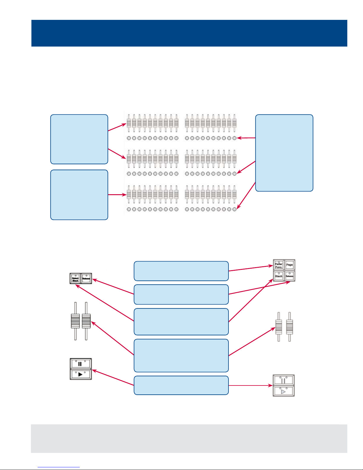
Figure 1 - ORB Front Panel Controls
Grand Master and
Blackout (Page 6)
Playbacks (Page 7)
User Denable Keys
(UDKs) (Page 11)
Control Wheels
(Page 12)
Keypad & Syntax
Keys (Page 10)
Function Keypad
(Page 9)
Master Playbacks
(Page 8)
Page 7

ORB XF
The ORB XF front panel controls have been divided into the following sections:
Figure 2 - ORB XF Front Panel Controls
Grand Master and
Blackout (Page 6)
Multi Function Faders
(Page 8)
User Denable Keys
(UDKs) (Page 11)
Control Wheels
(Page 12)
Keypad & Syntax
Keys (Page 10
Function Keypad
(Page 9)
Master Playbacks
(Page 8)
5
Page 8

6
Grand Master and Blackout
Figure 3 - Grand Master and Blackout
Grand Master and Blackout
The GRAND MASTER fader
allows you to temporarily limit
the output values of all dimmer
channels. The Grand Master
level is displayed on the monitor
screen task bar. In normal
operation the Grand Master
should be at 100%.
The BLACKOUT key enables
you to lock the dimmer outputs
from the desk at 0%, regardless
of the level of the Grand Master
Fader. Pressing the BLACKOUT
key toggles between enabled
and disabled. The red LED in the
BLACKOUT key ashes when
blackout is enabled and BLK is
displayed on the monitor screen.
Page 9

7
Playbacks
Playbacks - ORB
Playbacks are used as the main programming and playback area of ORB. These playbacks can function in one of two
ways - as Cue Lists (also known as Cue Stacks), or as Submasters.
The ORB has 10 playbacks, which can be paged between Page 1 and Page 100. Each page contains a new set of
10 playbacks, giving a total of 1000 playbacks available for programming.
Each playback has a number of controls available:
Figure 4 - Playbacks
A number of additional controls are available for releasing cue stacks and activating cue stacks on the Master Playback.
These are detailed in later sections.
The Master Fader
allows you to
override the
programmed
dimmer level.
A PAUSE key
temporarily stops
a fade whilst in
progress. Double
pressing the PAUSE
key acts as a BACK
function.
The GO key
advances to the next
programmed cue on
that stack.
A SELECT key
allows you to select
the playback for
programming or
manipulation on the
Master Playbacks.
The STACK PAGE
key is used to select
the required page
of playbacks, by
entering the required
number in syntax
(eg STACK PAGE 5
ENTER).
The currently active
page is indicated
on the LCD screen
above each playback, together with
the stack name,
current and next cue
information.
Page 10
Multi Function Faders - ORB XF
Multi Function Faders are used as the main programming and playback area of the ORB XF. These faders can function
in one of three ways - as Channels (Dimmers), Submasters (Scenes) or Cue Stacks (Playbacks).
The ORB XF has 60 MFFs, which can be paged to access all the channels, submasters and cue stacks on the desk.
Each MFF has a number of controls available:
Master Playbacks
The master playbacks allow for more advanced playback control: ORB XF
ORB
Figure 6 - Master Playbacks
8
Multi Function Faders & Master Playbacks
Figure 5 - Multi Function Faders
The bottom bank of
MFFs can also be
used as Playbacks.
In this mode, the
Flash button is used
as a GO button.
The Release key can be used to
release any of the Playbacks.
The (Select) Stack button can be
used for selecting a particular cue
stack for editing.
Two playback faders can be
assigned as A/B crossfade masters
or as an Intensity master and
override fader for the stack.
Large GO and PAUSE keys run and
stop cues on the selected stack.
The Fader Func. button is used to
switch the function of the MFFs.
Each Multi Function
Fader in the top
two banks offers
two possible
functions - Channel
or Submaster.
Below each MFF is
a ash button which
can be used to
ash, select, solo or
otherwise modify a
channel. The exact
behaviour of this
button is dened
by the type of fader
assigned.
Page 11

9
Function Keypad
Function Keypad
Figure 7 - Function Keypad
SETUP is used to enter and
exit SETUP and to congure
programmed items.
CUE ONLY is used when
programming to prevent the
changes in a cue applying to
later cues.
UPDATE allows you to merge
new information into existing
data.
NAME is used to set a name on
any programmed item.
DELETE is used to remove
programmed items.
TIME and DELAY are used to
adjust the fade and delay times.
COPY TO & MOVE TO are used
to relocate and copy data from
one place to another.
The CLEAR key is used to clear
out data from the programmer,
releasing those channels from
control.
TRY CUE lets you try out a
crossfade before programming
the cue.
LOAD allows you to bring back
a programmed item into the
programmer for alteration.
GROUP species a range
of channels to be controlled
together.
CUE and SUB allows you to
specify where you wish to record,
edit and playback information.
RECORD is used to store an
item.
TRACK allows you to record
cues tracking forwards from that
point.
SMART TAG allows you
to engage the Smart Tag
function to automatically tag
required channels.
BLIND allows you to enter and
leave BLIND mode, which can be
used for adjusting cues without
affecting the output of the desk.
VIEW allows you to alter the
monitor screen layouts and recall
programmed views.
Page 12

Keypads and Syntax Keys
Figure 8 - Keypads and Syntax Keys
10
Keypads & Syntax Keys
The syntax keys (and LCD)
follow syntax and provide
additional functions according
to what you've entered.
The + and - keys are used
for relative adjustment of
levels. e.g. 1 @ +10 ENTER
The / key is used for
separating cue & stack
numbers, or fade up/down
times.
The numeric keys (0-9) are
used for entering numeric
data (eg group no, palette no,
cue no, channel levels, DMX
addresses etc).
The UNDO key undoes the
last command entered.
The MACRO key allows you
to record and run macros to
speed up programming.
The SHIFT key alters the
function of most keys on the
desk.
The backspace key (f)
moves the last instruction
entered on the command line.
The . key is used to indicate
decimal points in cue names
and in syntax for setting 0%
intensity.
The ENTER key is used for
conrming of completing
commands.
The AT (@) key is used when
setting intensity levels or
DMX addresses.
The FULL key is used to set
the intensity of the selected
xture(s) to FULL (ie 100%).
The THRU key is used for
selecting a range of items.
The AND key is used for
adding items to a list.
The EXCEPT key is used for
removing items from a list.
Page 13

11
User Definable Keys
User Definable Keys (UDKs)
In addition to playbacks, ORB Series desks feature 10 User Deneable Keys (UDKs) which can be assigned to many
different functions.
Figure 9 - User Definable Keys (UDKs)
The current contents of the UDK
are displayed on the LCD display,
together with the current page
number.
The UDK page (ORB) can be
changed by pressing the UDK
PAGE button and entering the
required number in syntax (eg
UDK PAGE 4 ENTER). On ORB
XF this function uses the PAGE
key and a {UDK} softkey.
Pressing SHIFT and a UDK
opens the UDK Window on the
monitor to display the contents
of the UDKs.
Each key can be assigned a
different function (Macro, Palette,
Scene, etc) and action (Flash,
Latch, Solo, etc).
The HELP key (ORB XF) can be
used to access the online help
on ORB XF. On ORB, the ? in
the top right hand corner of the
monitor screens opens the Help
system.
Page 14
12
Attribute & Cursor Keys & Control Wheels
Attribute & Cursor Keys & Control Wheels
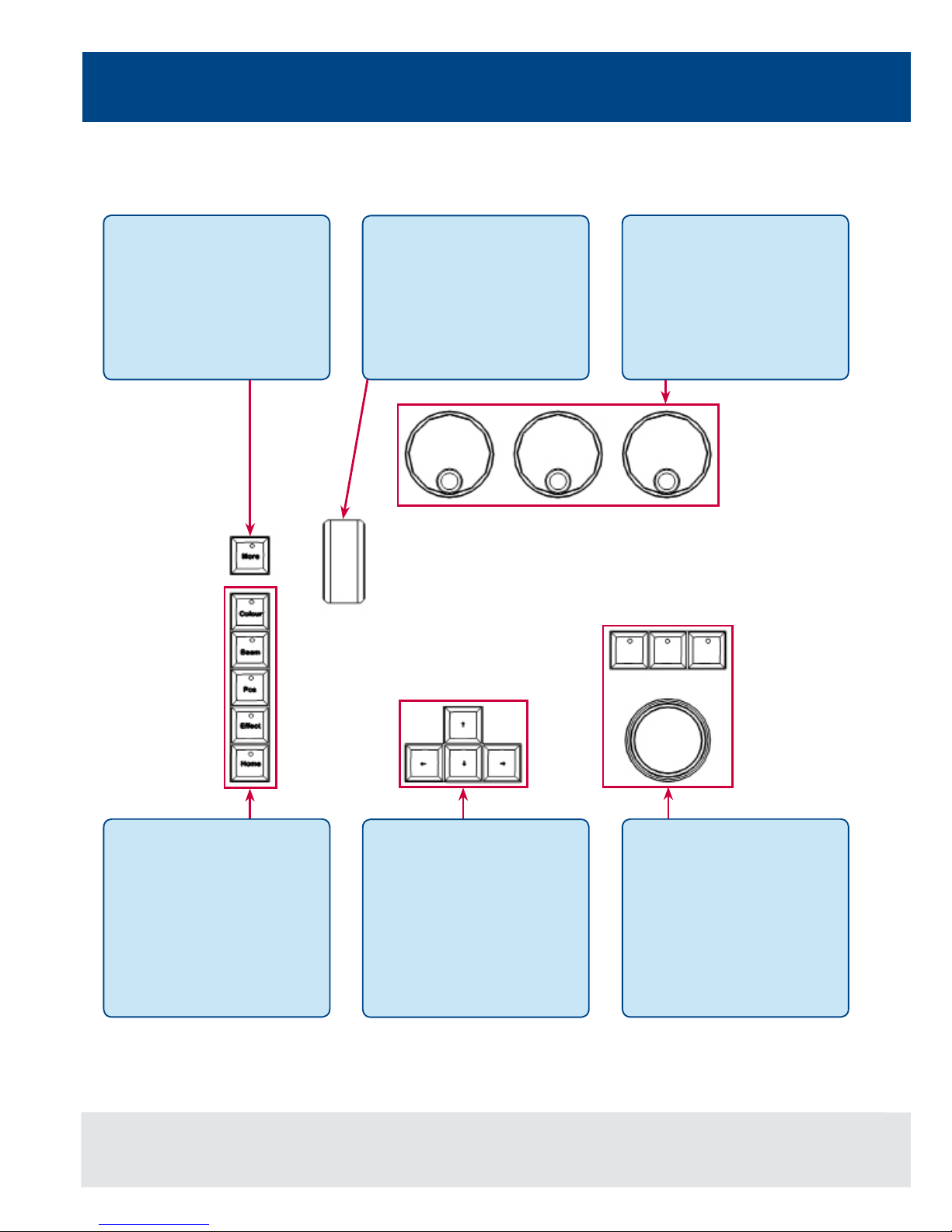
Figure 10 - Attribute & Cursor Keys & Control Wheels
The attribute keys (POSITION,
COLOUR, BEAM and EFFECTS)
are used when adjusting xture
parameters and also when
recording, referencing and
outputting palettes and effects.
Each of these keys contains
a yellow light, which is lit when
the attribute is selected.
The MORE key pages the
Syntax Keys to display more
options.
The intensity wheel is used for
adjusting the intensity of the
currently selected xture(s).
The intensity level is displayed
on the LCD screen above the
wheel.
The three control wheels are
used for setting and adjusting
xture parameters and other
data levels. The parameters that
are currently assigned to the
control wheels are shown on
the LCD, together with their
current value.
The trackball and three
trackball buttons are used for
manipulating the mouse on the
monitor screens, and also for
Position control of moving
lights. See page 143 of the
full User Manual for more
information.
The arrow keys are used to
move around elds on the
active monitor screen.
Page 15

13
Front Panel Controls
Quick Start Tutorial
Getting Started
Prior to powering up the desk, it is essential to attach all the peripherals you require. Both desks have support for
a USB Keyboard and Mouse, two XGA monitors (or touch screens) and a desk light on 3 pin XLR. These must be
connected before powering up as subsequent connection could result in software or hardware malfunctions.
Once you've connected all the peripherals you require, power on the desk using the switch on the rear panel. If you
see no immediate response, check you have the power switch set to ON, and that the IEC lead is rmly attached to
the power inlet.
When you power on the desk, the desk will run through its power up routine and after a short while you will be
presented with the desk software in its default conguration.
Setting Up the Desk
Before you start programming cues etc, you will need to set up the desk.
The desk comes with a default patch of channels - on ORB, 1 to 96 are assigned to DMX addresses 1 to 96 on DMX
universe 1 as standard Dimmer xtures. On ORB XF, 1 to 240 are assigned to 1 to 240 on DMX universe 1. If this
situation matches your installation then you can skip ahead from this section.
Press the SETUP key to display the Setup Window on Monitor 1.
Setup is intended to give you access to the core settings for the ORB desks. As such, you shouldn't need to enter
the Setup area during a show. It is, however also used for saving and loading of show les, so during programming
you may wish to enter Setup occasionally to take a backup.
Adding Fixtures
Once in the Setup screen, the rst task you need to perform is to assign the xtures in your rig to the desk’s xture
schedule.
Press the [Patch Wizard] button on the monitor using the trackball, using the left click button above the ball.
The Patch Wizard will appear and guide you through adding some xtures.
Page 16

14
Grand Master and Blackout
Figure 11 - Patch Wizard (Step 1 - Manufacturer Selection)
First the wizard allows you to select the xture manufacturer.
Scroll down or use the cursor keys to select the required manufacturer (eg MARTIN). If you have a keyboard connected,
you can press the M key to jump straight to manufacturers beginning with M.
Press the [Next] button (or ENTER on the keyboard) to move to the next step.
Figure 12 - Patch Wizard (Step 2 - Fixture Selection)
Scroll down or use the cursor keys to select the required xture type (eg MAC 700 Prole).
Note - Fixture Types
If the xture type you require is not in the xture library stored on the desk you can import the xture type - see Setup
chapter in the full manual for full details.
Quick Start Tutorial
Page 17

15
Quick Start Tutorial
Press the [Next] button to select the xture Mode. It is important that the mode set here matches the mode set on the
xture itself - if in doubt, consult the xture operating manual for full details.
Figure 13 - Patch Wizard (Step 3 - Mode Selection)
Once the Mode has been selected, press the [Next] button to move on and enter the DMX address for the xture.
If you have not yet set this on the xtures themselves, press the [Next Address] button and the desk will calculate
a DMX address for you based on the existing patch information.
It is important here to ensure that the correct DMX universe is selected.
Figure 14 - Patch Wizard (Step 4 - DMX Address Entry)
Once the address is congured, press the [Next] button and enter the quantity of the xture required. The monitor screen
will tell you the number of xtures and control channels remaining to ensure you do not exceed these limits.
The nal step in the Patch Wizard is to assign a xture number to the xtures. The xture number is the number you will
refer to the xture as within the desk software. Enter the number and press [Finish].
Page 18

Figure 15 - Patch Wizard (Step 5 - Quantity)
The Patch Wizard is now complete and your xtures have been assigned. The xtures should now have moved to their
Home positions.
You can repeat the Patch Wizard for every group of xtures you have.
Exiting Setup
Once you have nished making changes to the setup, press the [SETUP] button to leave Setup. The indicator light
will go out to inform you that you have exited Setup mode.
16
Quick Start Tutorial
Page 19

17
Main User Interface
Main User Interface
Figure 16 - Main User Interface
The command line shows the
commands you've entered on
both monitors.
The cue stack window shows
the selected cue stack and all
the cues which that stack
contains.
The group window shows
groups of all your xtures.
The Output Window is central to the operation of the ORB Series. It is
recommended that the Output Window is displayed on one of the monitor
screens when programming cues, palettes, UDKs etc. The colour coding
also helps to see what direction a channel has faded.
The palette windows show the
various recorded palettes and
can be clicked to access a
palette (or pressed if using a
touchscreen).
Page 20

18
Controlling Dimmers
Controlling Dimmers
The intensity parameter of xture(s) can be controlled by entering commands directly via the numeric keypad
or by using the corresponding control wheel.
Intensity levels can be set for a single xture or a number of xtures using the following syntax:
1 @ N ENTER
This sets the intensity output of xture 1 to N %.
1 FULL ENTER
This sets the intensity output of xture 1 to 100 %.
2 AND 3 @ N ENTER
This sets the intensity output of xtures 2 and 3 to N %.
2 AND 3 FULL ENTER
This sets the intensity output of xtures 2 and 3 to 100 %.
5 THRU 10 @ N ENTER
This sets the intensity output of xtures 5 to 10 to N %.
5 THRU 10 EXCEPT 7 @ {wheel}
This sets the intensity of channels 5,6,8,9,10 to the level on the wheel
5 THRU 10 FULL ENTER
sets the intensity output of xtures 5 to 10 to 100 %.
Using the Control Wheel
The Intensity channel of a xture can also be adjusted by control wheel.
First select the xture(s) required as described above and then use the intensity wheel to adjust the level.
The output value is shown on the LCD screen above the corresponding control wheel.
Using the MFFs (ORB XF only)
The Intensity channel of a xture can also be adjusted by using the MFFs on ORB XF.
First ensure that the MFFs are running in Channel mode – this is indicated by the LED in Fader Func. being lit Green.
If the MFFs aren’t in Channel mode, press Fader Func., then select {Channels} {1-60} on the Syntax LCD.
With the MFFs in the correct mode, channels can be adjusted by moving the appropriate fader. If a channel already
has a level, for example set through syntax, then you must ‘grab’ the level by moving the fader up to the present
value. Once that value is grabbed, the MFF gains control.
Tip - No Intensity Output?
If the intensity output levels do not change when you send any of the above commands to a xture, or adjust
the intensity level using the wheel, check that the GRAND MASTER fader is at full and the BLACKOUT button
is off. If the selected xture(s) have a Shutter parameter, check that the shutter is open. Check that the
Highlight key is not active by holding SHIFT and pressing HOME. For more troubleshooting tips, see page
156 of the full user manual.
Page 21

19
Controlling Fixtures
Controlling Fixtures
Fixtures on the ORB Series are considered to be any multi-channel device, such as a moving light, LED, lamp with
a scroller, etc. These must be patched before they can be controlled.
Selecting Fixtures
Fixtures are selected numerically using the number assigned to them during the Patch Wizard. Type the xture number(s)
followed by ENTER to select those xtures. Fixtures are also selected if an intensity command (above) is entered.
Homing the Fixtures
If you are unsure which xture is which, the easiest way to see which xtures in the rig you are controlling is to ‘home’
them. This will set their position (Pan and Tilt) to 50%, the dimmer to 100% with an open white beam (no gobos or
effects). The home values can be customised in the Edit Fixtures menu in Setup.
After selecting a xture, press the HOME key. This will send the xtures to its ‘home’ values and automatically tags the
xture parameters for programming.
Controlling Fixture Parameters
Each xture type has it’s own set of parameters (Intensity, Colour, Gobo, Pan, Tilt etc. as dened in the xture library)
which are classied or grouped together in different attributes (Position, Colour, Beam).
Once a xture, or group of xtures has been selected, the attribute buttons and control wheels can be used to adjust
the parameter output levels as required.
Controlling Colour, Beamshape and Position Parameters
The colour, beamshape and position parameters of the selected xture(s) are controlled using the control wheels.
First select the required xture(s) and then press one of the attribute keys (POSITION, COLOUR or BEAM).
The corresponding parameters for the xture are assigned to the control wheels and are indicated on the lower part
of the LCD touch screen.
If the xture has more than three controllable parameters for the selected attribute, pressing the attribute key selects
the next group of parameters.
Page 22

20
Tagging Parameters
On the ORB Series xture parameters must be ‘tagged’ for them to be recorded when programming cues, palettes
and UDK’s.
The tag status of each xture parameter is indicated on the LCD screen and in the Output Window by it’s background
colour - dark background indicates that the parameter is untagged; bright background indicates that the parameter is
tagged.
If a parameter’s value is changed by a command (moving the control wheel or directly in the Output Window) it will
be tagged automatically.
Figure 17 - Output Window (Tagged & Untagged channels)
It is also possible to tag and untag xture parameters manually by holding down CLEAR and moving a xture wheel,
then releasing CLEAR.
Only tagged channels will be recorded when storing a cue, palette, UDK, etc. This gives the capability of separating
your programming between multiple UDKs, cue stacks, submasters, etc.
Tagging Parameters
Tagged
Untagged
Page 23

21
Cues
Cues
Once you have set up a scene that you like you can then record that into a cue.
Selecting a Cue Stack
Cues can be programmed into any of the 1000 user programmable cue stacks.
On an ORB, press the SELECT button above the cue stack you wish to program in. The LED in the SELECT button
illuminates to indicate that it is the active cue stack.
On an ORB XF, enter the syntax STACK n ENTER.
Recording a Cue
To record a cue, simply enter the command:
RECORD CUE n ENTER
Where N is the number of the cue you wish to record. As you have not specied any fade times or names, the desk
will enter the default values for the cue and the cue will be recorded.
After recording a cue, the command line is cleared, the xtures remain selected but the parameters are untagged.
Subsequent cues can then be set up and recorded using the same method.
As you become more experienced with the desk, you will nd the most efcient way of programming your cues -
for more methods. (See Page 96 of the full User Manual).
Note - Record Options Window
When you press the RECORD key the Record Options Window is displayed. This window allows you to adjust what
data is recorded, as required - see the Programming chapter (Page 86 of the full User Manual for further details).
Adjusting Fade and Delay Times
As well as the actual output levels recorded in the cue, each xture parameter also has it’s own fade and delay times.
Default fade and delay times for Intensity, Colour, Beamshape and Position are dened in Desk Setup and can be
adjusted if required, prior to programming cues.
Once a cue has been programmed its times can be adjusted by using the following syntax:
CUE n TIME x DELAY y COLOUR {Fade} z ENTER
Any adjusted fade times display on the monitor in the Cue Stack window, which can also be manipulated using the
cursor keys and ENTER button in a similar format to a spreadsheet on a computer.
Page 24

Naming Cues
Each cue can have a name stored alongside the cue data. Enter the following syntax command:
CUE n NAME {your name} ENTER
Playing Back Cues
Before playing back the programmed cues in a cue stack it is important to clear the programmer by pressing
the CLEAR button. This removes any unrecorded commands and sends xtures to their default values, with the
exception of the intensity, which is kept at 0%.
To play back the cues in a cue stack in sequence rst select the required page of playbacks.
Press the GO button for the selected playback, and raise the master fader to full. These commands can be executed
in either order, as sometimes a manual fade is desirable.
Pressing the GO button will trigger the start of fades on all parameters, but the intensity channels are mixed with the
master fader.
To output the next memory in the stack, simply press the GO button again. The desk will continue down the cue
list one cue at a time. Once the end of the cue stack is reached the rst cue will be selected as the next memory
resulting in a loop.
Once you have nished playing back cues it is important to release the cue stack. This returns all of the affected
xtures to their default values, or to the value they were at before the cue stack was executed.
Select the cue stack, using the SELECT button, then press the RELEASE key.
Updating Cues
In order to update a cue the rst thing to do is to ensure that the cue is outputting. If it is not outputting,
enter the syntax:
CUE n GO
Once the cue is outputting, make any changes using command syntax, xture wheels and palettes as required.
To record the changes to the cue press the UPDATE key. The Update Options window will appear.
Select the cue number you wish to update in that window and press OK. The cue will inherit the new
information and the update will be complete.
Cues
22
Page 25

23
Tracking
Tracking
There are two operating modes that the ORB range supports - Tracking or Non Tracking Mode. In Tracking Mode,
every cue programmed behaves in a Tracking methodology. This means that each cue only programs the changes
between two states. Channels are told to fade up, fade down or if no instructions are programmed the channel will
stay the same. This is a powerful programming method as it allows advanced manipulation of the cue stack and
updates can be ltered through entire sequences without having to update each cue individually.
When updating a cue there are four tracking options available - Track Forward, Track Backward, Track Both or Cue
Only. For a full explanation of each of these options see page 128 of the full User Manual.
Selecting Cue Only forces the update only to affect the cue you are updating.
Choosing Track Forwards allows the update to follow through into the following cues. If you choose to update with
Track Forwards enabled, remember to ‘undo’ the change you made in one scene when you move to the next -
particularly if the next cue is a blackout.
Non Tracking mode eliminates these choices making programming simpler but restricts the exibility of your
programming capabilities.
Figure 18 - Update Options Window
Page 26

24
Palettes
The ORB Series has four sets of 1000 palettes.
A palette is a programming tool which allows you to dene the values required in a xture or group of xtures to
create a particular affect on stage. For example, a palette can be stored for the colour Red which details the DMX
values required for each moving light to create a red colour. Likewise a palette can be stored for a position on the
stage, with the relevant Pan & Tilt information for each xture in the rig.
Figure 19 - Palette Windows
Recording Palettes
Programming a palette is simple and very similar to recording a cue.
Set up the xture outputs as required, ensuring that the correct parameters are tagged. To record the data as
a colour palette, enter the following command:
RECORD COLOUR n ENTER
To record the data as a beamshape, position or effects palette, simply replace the COLOUR part of the above
command with BEAM, POSITION or EFFECTS.
Palette Windows
Each set of palettes has it’s own palette window. These palette windows are displayed on Monitor 2 by default.
The palette window contains a soft button for each of the 1000 palettes. These buttons can be clicked or pressed if
using a Touch screen to access a palette. Unprogrammed palettes are indicated by a * next to the number.
Palettes
Page 27

Naming Palettes
As well as containing channel data a palette can have a name associated with it. To assign a name to a palette enter
the command:
COLOUR n NAME {your name} ENTER
These names are displayed in the palette windows and in the command line when a palette is accessed.
Outputting Palettes
The act of outputting a palette causes the selected xtures to move to the value stored within that palette.
To apply or output a palette rst select a xture or group of xtures.
Enter the command COLOUR n ENTER
The xture(s) will change to the colour they were in when the palette was stored.
If any of the selected xtures are not actually programmed in the applied palette, but there are one or more xtures of
the same type that are programmed, the xture will use the values programmed for the rst xture of the same type.
If the xture data in the programmer is then recorded into a cue, submaster or UDK, the desk will record the palette
reference rather than the actual parameter value. This is especially useful for touring shows when using positions, to
save updating each cue individually.
Automatic Palettes
In Setup, there is an option to generate a set of automatic palettes based on the xture types in the schedule. The desk
generates palettes for a range of useful things based upon your current patch.
To create the automatic groups, rst enter SETUP, press the [Auto Menus] soft key on the monitor, select the [Create
Auto Palettes] option, then exit Setup.
Palettes
25
Page 28

User Definable Keys
The desk provides 10 user denable keys, which can be paged 20 times to give 200 programmable locations.
The user denable keys may be assigned to Groups, Individual Fixtures, Palettes, Cues, or Channel Data.
Assigning User Definable Keys
In this quick start guide we will just look at recording channel data to a UDK. For details of all the other items that can
be assigned to UDK’s see the UDK chapter (Page 111 in full user manual).
Set up the xture outputs as required, ensuring that the correct parameters are tagged. To record the data to a User
Dened Key, enter the following command:
RECORD <UDK>
Outputting User Definable Keys
The data assigned to a UDK is output by pressing the UDK on the front panel or by clicking on the soft button in the
User Dened Keys Window on the monitor.
The action of the UDK can be set to either Flash or Latch in the User Denable Keys Setup Window. (See UDK
section of the full User Manual (Page 111) for more information).
User Definable Keys
26
Page 29

Groups
As well as palettes the ORB provides 1000 user denable Groups.
Groups are most commonly used when selecting xtures and programming data to be recorded in cues, palettes etc.
Groups can also be assigned to User Denable Keys (UDKs).
Automatic Groups
In Setup there is an option to generate a set of automatic groups based on the xture types in the schedule. The desk
generates a group for each of the types of xtures you have, plus ‘odd’ and ‘even’ groups for each different xture type
in the schedule.
To create the automatic groups, rst enter SETUP, press the [Auto Menus] soft key on the touch screen, select the
[Create Auto Groups] option, then exit Setup.
User Defined Groups
You can create your own groups of xtures, eg Floor MAC 700’s, FOH MAC 700’s etc.
Simply select the xtures that you wish to be in the group and then enter the command:
RECORD GROUP n ENTER
Group Window
The Group Window is displayed by default in the bottom right hand corner of Monitor 2 on ORB. To display it on
ORB XF, hold down SHIFT and press GROUP. This window allows you to click and select any of the programmed
groups automatically.
Figure 20 - Group Window (bottom right)
Groups
27
Page 30

Multi Function Faders
The ORB XF features 60 Multi Function Faders, which operate in three modes. MFFs can be switched by using the
Fader Func. key.
In Channel Mode all 60 faders function as controls for the dimmers of patched xtures. This is indicated by the MFF
window being dark blue.
Figure 21 - MFF Window (Channel Mode)
In Submaster Mode all 60 faders function as submasters. This is indicated by the MFF window being light red:
Figure 22 - MFF Window (Submaster Mode)
Multi Function Faders (ORB XF only)
28
Page 31

Multi Function Faders (ORB XF only)
In Playback Mode the bottom 20 faders convert into playbacks (cue stacks). In this mode the ash button acts as a GO
button. This is indicated by these twenty faders turning green. It is possible to mix Playback mode with either Channel
Mode or Submaster Mode - simply switch to the preferred mode rst, then change to Playbacks.
To change mode, simply use the syntax:
FADER FUNC. {Channels} {1-60}
FADER FUNC {Submasters}
Or
FADER FUNC. {Playbacks}
Figure 23 - MFF Window (Playback Mode)
Submasters
The ORB Series supports upto 60 submasters, which can be paged 20 times to give upto 1200 programmable locations
for scenes stored onto faders. On ORB, submasters can be accessed either by altering the mode of the playbacks, or by
using another DMX enabled desk and using DMX In. On ORB XF the submasters can be activated on the MFFs.
To convert a playback into a submaster on ORB:
Hold SETUP and press the SELECT key above the playback.
In the popup window, select <Submaster>
Press OK.
To activate submasters on MFFs on ORB XF, enter the syntax:
FADER FUNC. {SUBMASTERS} ENTER
29
Page 32

Submasters
30
Recording Submasters
Before recording a submaster ensure that you have the number of submasters per page dened as you require it.
This setting is found in Desk Setup / Inputs.
To record a submaster, rst set up the xture outputs as required, ensuring that the correct parameters are tagged.
To record the data to a submaster, enter the following command:
RECORD SUB n ENTER
To record to a specic page, enter:
RECORD SUB m / n ENTER
It is also possible to record a submaster by pressing the FLASH or GO key underneath it - eg:
RECORD <FLASH> (on ORB XF when the MFFs are in Submaster mode)
RECORD <GO> (on ORB when the playback is in Submaster mode)
You can view programmed submasters in the Submasters window, by holding SHIFT and pressing SUB.
Replaying Submasters
In this quick start guide we will just look at using the on-board controls. For details relating to DMX In submasters, see the
Submasters chapter of the full User Manual (page 115).
Ensure you have converted the Playback into a Submaster (ORB) or activated the MFF Submasters function (ORB XF).
Raising the submaster fader will activate the submaster controls - the intensity will be relative to the level of the fader and
the attributes will trigger at 5%.
Lowering the submaster will remove the submaster from the outputs and release any attributes.
Paging Submasters
To change the page of the submasters enter the syntax:
SUB {Page} n ENTER
When you change page the submasters which are currently active stay active on the previous page until you take the
fader down. Once released from a previous page, the submasters become available on the new page. This is known
as Page Holdover.
Page 33

Saving Shows
The ORB Series will save the show automatically to its internal memory at regular intervals.
External backups of the show data can be made to a USB Storage Device (eg the memory stick included with your ORB /
ORB XF).
• Saving the show is done in Setup mode, so rst press SETUP
• Press the [Files] key on the monitor.
• Press the [Save Show] key to enter the Save Show screen.
• Press the Destination Device key to select the required device.
• If the device does not appear straight away, wait a few seconds and then click [Refresh].
• Type the show name in the Filename box using an external keyboard or the numeric keypad on the desk.
• Press the [OK] key.
• After a few seconds, the show will be saved.
• Press SETUP to exit Setup mode.
Saving the show takes all of the available information in the desk, including monitor congurations, setup
options, patch, cue and palette data and stores it all into a single le on your destination device. This le can
then be reloaded at a later date to return the desk to the same state as it was in when you saved it.
Figure 24 - Save Show
Saving Shows
31
Page 34

Loading Shows
Shows can be loaded onto the ORB Series from a USB Storage Device.
• Loading shows is done from within SETUP, so rst press SETUP to enter Setup.
• Insert or connect the storage medium containing the show.
• Press the [Files] key on the monitor.
• Press the [Load Show] key to enter the Load Show screen.
• Press the Source Device key to select the required device.
• A list of show les on the currently selected storage device appears on the touch screen.
• Select the show le you wish to load using the cursor keys.
• Press [OK] key to load the show.
• The desk will load the show into its memory and you will be returned to the home screen.
Loading a show brings back the desk to the same settings that were dened when the show was stored - Patch
information, Cue Information, UDKs, Submasters, Palettes, Groups, Macros, Desk Setup and Network settings will
all be restored.
Figure 25 - Load Show
This ends the quick start tutorial. Please take time to experiment with the consoles as the best way of learning
is through exploring. In the full User Manual we will go into a lot more detail about each section of the desk.
Consider this a reference section, which can be referred to when needed whilst learning and programming
the consoles.
Loading Shows
32
Page 35

33
Page 36

E&OE Stock number: 73-778-00 Issue 2.0 Cooper Controls reserve the right to make changes to the equipment without prior notice © Cooper Controls Ltd 2010
Usk House, Lakeside,
Cwmbran, NP44 3HD. UK
Tel: +44 (0)1633 838088
Fax: +44 (0)1633 867880
Email: sales@zero88.com
www.zero88.com
Cooper Industries
600 Travis, Ste. 5800
Houston, TX 77002-1001
P: 713-209-8400
www.cooperindustries.com
International
Usk House,
Lakeside, Cwmbran
Gwent, NP44 3HD. UK
Tel: +44 (0)1633 838088
Fax: +44 (0)1633 867880
Email: sales@coopercontrols.co.uk
North America
203 Cooper Circle
Peachtree City,
GA 30269. USA
Tel: +1-800-553-3879
Fax: +1-800-954-7016
Email: controls@cooperindustries.com
Cooper Controls Ltd
www.coopercontrol.com
DEALER
 Loading...