

Page 1

ORB
OPERATING MANUAL
Page 2

ORB OPERATING MANUAL
If a portable or temporary three phase
mains supply is used to power this desk,
we recommend that the desk mains plug
is removed before connecting or
disconnecting the supply. Serious damage
will occur if the desk is connected across
two phases.
This equipment is designed for use as a
lighting control desk only, and is
unsuitable for any other purpose. It
should only be used by, or under the
supervision of, an appropriately qualified
or trained person.
Zero 88 reserves the right to make
changes to the equipment described in
this manual without prior notice. E & OE.
Federal Communications Commission
This equipment has been tested and found to
comply with the limits for a Class A digital
device, pursuant to part 15 of the FCC rules.
These limits are designed to provide reasonable
protection against harmful interference when the
equipment is operated in a commercial
environment. This equipment generates, uses,
and can radiate radio frequency energy and, if
not installed and used in accordance with the
instruction manual, may cause harmful
interference to radio communications. Operation
of this equipment in a residential area is likely to
cause unacceptable interference in which case
the user will be required to correct the
interference at the operators expense.
IM 8755 Issue 1.0 – April 2009
Software Version 5.0
© Zero 88 2009
Cooper Controls t/a Zero 88
Usk House
Llantarnam Park
Cwmbran
NP44 3HD
United Kingdom
Tel: +44 (0)1633 838088 *
Fax: +44 (0)1633 867880
e-mail:
sales@zero88.com
Web: www.zero88.com
* 24 hour answerphone
Page 3

Table of Contents
Table of Contents..............................3
Introduction ........................................6
This Manual .....................................6
The ORB Lighting Desk ......................6
Front Panel Controls..........................9
Quick Start Tutorial ............................ 17
Getting Started............................... 17
Setting Up the Desk........................17
Adding Fixtures .............................. 17
Exiting Setup ................................. 19
The main user interface ...................20
Controlling Dimmers........................ 21
Controlling Fixtures......................... 22
Cues.............................................23
Palettes......................................... 25
User Definable Keys (UDK)............... 27
Groups.......................................... 27
Group Window................................ 28
Submasters ................................... 28
Saving Shows................................. 29
Loading Shows ............................... 30
Setup...............................................31
Patch ............................................ 32
Adding Fixtures .............................. 32
Add Fixtures...................................32
Patching Fixtures.............................34
Patch Views....................................37
Patch Wizard ..................................39
Editing Fixtures...............................42
Auto Menus....................................47
Desk Setup ....................................49
Peripheral ......................................52
Files..............................................59
Clear Options..................................63
Network.........................................64
The Output Window ............................71
Programming.....................................74
Tagging Parameters.........................76
Smart Tags ....................................76
The Command Line..........................77
Basic Record Commands ..................77
Clear.............................................77
Updating ...........................................78
Update Options Window ...................78
Groups..............................................80
What are Groups? ...........................80
Automatic Groups............................80
User Defined Groups........................80
Naming Groups...............................80
Copying Groups ..............................80
Moving Groups............................... 81
Deleting Groups ............................. 81
Group Window ............................... 81
Palettes............................................ 82
What are Palettes?.......................... 82
Recording Palettes.......................... 82
Naming Palettes ............................. 82
Outputting Palettes......................... 82
Updating Palettes ........................... 83
Copying Palettes............................. 83
Moving Palettes.............................. 83
Deleting Palettes ............................ 83
Palette Windows............................. 84
Cues, Stacks and Pages...................... 85
Cues............................................. 85
Programming Cues ......................... 85
Naming Cues ................................. 86
Editing Cue Output Levels................ 86
Editing Cue Fade and Delay Times..... 87
Editing Cue Triggers........................ 87
Changing the Next Cue.................... 88
Adding Macros to Cues.................... 88
The Cue Stack Window.................... 88
Playing Back Cues........................... 90
Copying Cues................................. 92
Moving Cues.................................. 92
Page 4

Page 4 ORB Operating Manual – Issue 1.0
Deleting Cues................................. 92
Cue Stacks .................................... 92
Cue Stack Directory Window............. 92
Naming Cue Stacks......................... 93
Copying Cue Stacks ........................ 93
Moving Cue Stacks.......................... 93
Deleting Cue Stacks........................93
Cue Stack Setup Window ................. 94
Chases.......................................... 96
Pages............................................ 98
Loading a Page onto the Playbacks.... 98
Naming Pages ................................ 98
Page Window ................................. 98
User Definable Keys (UDKs)............... 100
Channel Data UDK ........................ 100
Cue UDK...................................... 100
The UDK Setup Window................. 100
Naming UDKs............................... 101
Group UDK .................................. 101
Fixture UDK ................................. 102
Palette UDK ................................. 102
Macro UDK................................... 102
Changing UDK Page ...................... 102
The UDK Window.......................... 102
Editing User Definable Keys............ 103
Deleting User Definable Keys.......... 103
Submasters .....................................104
Location of Submasters..................104
The Submasters Window................104
Recording Submasters ...................104
Playing Back Submasters................105
Chase Submasters.........................105
Using Playbacks as Submasters....... 105
The Submaster Setup Window.........105
Changing Submaster Page.............. 106
Fade Times on Submasters.............107
Editing Submasters ....................... 107
Previewing Submasters.................. 107
Copying Submasters...................... 107
Moving Submasters.......................107
Deleting Submasters......................107
Effects ............................................108
The Effects Palette Window............. 108
Auto Effects.................................. 108
Effect Parameters on the Wheels .....109
Applying Effects............................109
The Effects Window .......................109
Recording Effects .......................... 110
Naming Effects ............................. 110
Applying Effects............................110
Copying Effects............................. 110
Moving Effects ..............................111
Deleting Effects.............................111
Macros ............................................112
In Built Macros..............................112
The Macro Window.........................112
Recording a Macro.........................113
Naming a Macro ............................113
Running a Macro ...........................113
Copying a Macro............................113
Moving a Macro.............................113
Deleting a Macro ...........................113
Auto Macros..................................114
Advanced Programming.....................115
Record Options Window..................115
Wheel Editing Modes......................118
Knockout Function.........................120
Park Function................................120
Rem Dim Function .........................120
Fade and Delay Times....................120
Fade Time Commands....................121
Try Cue Function ...........................121
Highlight Function..........................121
Home Function..............................122
Remote ...........................................123
Other Features .................................124
Windows ......................................124
Screen Navigation Keys..................125
Page 5

Mouse Operation on Windows......... 125
Trackball ..................................... 126
Preview Cue Window..................... 126
Preview Palette Windows................ 127
Preview Group Window.................. 128
Preview UDK Window .................... 128
Preview Macro Window .................. 129
Active Playback Window................. 129
DMX Output Window ..................... 129
User Views................................... 130
Software Updates ......................... 131
Glossary ......................................... 132
Technical Specification...................... 136
Mains Inlet................................... 136
Audio.......................................... 136
Remote Input............................... 136
SMPTE......................................... 137
MIDI........................................... 137
Video Output................................ 137
CAN Port ..................................... 137
Ethernet...................................... 137
USB Ports.................................... 137
Keyboard & Mouse........................ 137
Touchscreens ............................... 137
External Storage Devices ............... 137
AV Port........................................ 137
Desk Light.................................... 138
DMX Input....................................138
DMX Output ................................. 138
Kensington Lock............................ 138
Operating Environment ..................138
Troubleshooting ............................... 139
No DMX Output? ........................... 139
Fixtures Not Responding?............... 139
No Intensity Output ? .................... 139
Desk Does Not Boot....................... 139
Software Installation Problems........ 139
Front Panel not responding?............139
Reporting a problem...................... 140
Basic Maintenance............................140
Quick Reference Sheet ......................141
Fixture Types supported by ORB...... 143
Index..............................................158
Page 6

Introduction
Page 6 ORB Operating Manual – Issue 1.0
Introduction
This Manual
This manual describes the operation of the ORB lighting desk. This
chapter contains an overview of the capabilities and controls of the
ORB.
The Quick Start Tutorial chapter is designed to get you up and
running with the desk, but is not a substitute for the whole manual.
For more detail on each function, this manual is divided into
chapters, one for each major area of control.
As the ORB is a powerful lighting desk which can be set up in many
different ways, experience is the best way of fully learning the desk .
Through time you will develop your own operating style.
Throughout this manual the following conventions are used:
References to front panel controls, buttons and lights appear in
capital letters, for example:
GRAND MASTER, COLOUR, <UDK3>.
Soft buttons which appear on the monitor are displayed as follows:
[Desk Setup], [Values].
Syntax keys which appear on the LCD screen above the main
keypad are displayed as follows:
{Knockout}, {Close}, {Merge}.
The ORB Lighting Desk
The following section is a summary of the main functions of the ORB
lighting desk.
Graphical Interface
The desk operates a graphical interface which is provided by up to
two external monitors.
All the setup, programming, playback and output information is
displayed graphically on the monitor screens.
The desk provides two XGA outputs on the rear panel of the desk.
The monitors are used extensively to display information and
shortcut buttons.
Two touch screens can be connected to the desk via VGA and USB
ports as an option to provide you with easier input facilities.
Keys on the front panel enable quick and direct access to the
various monitor screens.
Cursor keys and an internal trackball on the front panel allow you to
move around the monitor. These functions can optionally be
mimicked using a USB keyboard and mouse.
Command Line
The primary method of programming ORB is via a command line,
which is displayed on the monitors. Commands can be entered
using the front panel keys, control wheels, external keyboard or by
clicking on objects with the mouse or trackball.
Above the command line is a Suggested Commands bar which
indicates the next available keys in your command syntax.
Page 7

Introduction
ORB Operating Manual – Issue 1.0 Page 7
Control Channels
The desk has 2048 channels of control. These can be assigned and
patched as any number of Fixtures, across the 4 DMX universes on
the desk.
Fixtures
Every device controlled by ORB is known as a Fixture. Fixtures can
be a simple generic dimmer channel, or a complex DMX device such
as a colour scroller, moving mirror or moving head (eg VL3000,
MAC 700). Any item controllable via a DMX signal can be assigned
as a fixture on ORB.
On the ORB, dimmer channels are a simple fixture with one
parameter. Moving heads, moving mirrors, LED and Video systems
controlled by DMX are fixtures with multiple parameters.
Within the Fixture Library, the ORB is told which channels cont rol
which parameters of the fixture. These are then grouped into
Position, Colour and Beamshape.
Fixtures can be given a user defined name and number, for ease of
reference.
Fixtures can be patched to any of the DMX output channels (1 –
512) on any of the DMX universes (1 – 4).
Fixture parameters can be manipulated from within the Output
Window, from where they can be added to cues, palettes,
submasters, User Defined Keys, or macros.
Cues, Cue Stacks and Playbacks
The desk allows you to record cues, for use in any of the 1000 user
programmable cue stacks. Each cue can have a number, name,
trigger, a wait time (auto cues) and a set of delay, and fade times.
It is possible to give each parameter of each fixture their own
individual fade and delay times in each cue.
The desk provides 10 playbacks, which can be switched between
100 pages.
Groups
The desk provides 1000 user definable groups. Automatic groups
for each fixture type in the schedule can be generated from the
Setup area, if required.
Palettes
The desk provides 1000 user programmable palettes for each of the
four attributes (Colour, Beamshape, Position and Effects).
User Definable Keys (UDKs)
The desk provides 20 pages of 10 User Definable Keys. The User
Definable Keys may be assigned to Groups, Fixtures, Palettes,
Effects, Cues, or channel data.
Submasters
The desk provides 20 pages of upto 30 Submasters. The
submasters may be played back via DMX In or using the Playback
Masters.
Output Processing on the ORB Desk
The ORB has two distinct channel types: Intensity channels and
Attribute channels (Colour, Beam and Position).
The main difference is that Intensity channels can be flashed, are
mixed with their source's Master Fader and the GRAND MASTER,
and can have distinct Fade Up and Down times.
When you play back a cue, park a channel, or manually manipulate
a channel in the programmer, you give ownership of the channel to
that specific area of the desk.
Page 8

Introduction
Page 8 ORB Operating Manual – Issue 1.0
When a channel is owned, the programmed value (or series of
values, if it is defined as a chase or effect) is output. However, the
previous owner(s) are not forgotten, and go into in a history list.
When a cue is released, it loses it's places in the history, wh ether it
currently owns them or not. The most recent owner in the history
will then regain ownership, and hence control the output of that
channel.
If a channel is not owned by any source, then it will output zero for
an Intensity channel, or it's default value for an Attr ibute channel.
Page 9

Introduction
ORB Operating Manual – Issue 1.0 Page 9
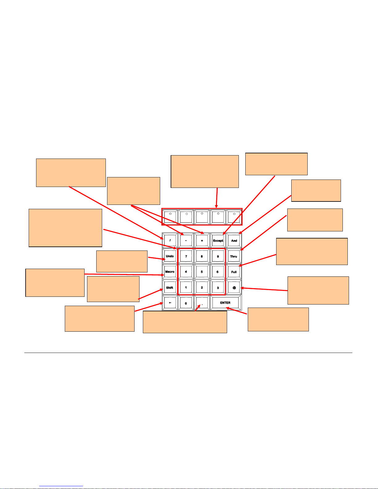
Front Panel Controls
This section of the manual describes the controls and displays on the front panel of the ORB desk. The front panel controls have been divided
into the following sections:
Figure 1 - Front Panel Controls
Grand Master and
Blackout (Page 10)
Playbacks (Page 11)
Keypad & Syntax
Keys (Page 13)
Master Playbacks
(Page 13)
User Definable Keys
(UDKs) (Page 14)
Control Wheels
(Page 15)
Function Keypad
(Page 12)
Page 10

Introduction
Page 10 ORB Operating Manual – Issue 1.0
Grand Master and Blackout
Figure 2 - Grand Master & Blackout
The BLACKOUT key enables
you to lock the dimmer outputs
from the desk at 0%,
regardless of the level of the
Grand Master fader. Pressing
the BLACKOUT key toggles
between enabled and disabled.
The red LED in the BLACKOUT
key flashes when blackout is
enabled and BLK is displayed
on the monitor screen.
The GRAND MASTER fader
allows you to temporarily
limit the output values of all
dimmer channels. The
Grand Master level is
displayed on the monitor
screen task bar. In normal
operation the Grand Master
should be at 100%.
Page 11

Introduction
ORB Operating Manual – Issue 1.0 Page 11
Playbacks
Playbacks are used as the main programming and playback area of ORB. These playbacks can function in one of two ways – as Cue Lists (also
known as Cue Stacks), or as Submasters.
The ORB has 10 playbacks, which can be paged between Page 1 and Page 100. Each page contains a new set of 10 playbacks, giving a total of
1000 playbacks available for programming.
Each playback has a number of controls available:
Figure 3 - Playbacks
A number of additional controls are available for releasing cue stacks and activating cue stacks on the Master Playback. These are detailed in
later sections.
The currently active page is indicated on
the LCD screen above each playback,
together with the stack name, current
and next cue information.
The Master Fader allows
you to override the
programmed dimmer level.
The GO key advances to
the next programmed
cue on that stack.
A select key allows you to
select the playback for
programming or manipulation
on the Master Playbacks.
A PAUSE key temporarily
stops a fade whilst in
progress. Double
pressing the PAUSE key
acts as a BACK function.
The STACK PAGE key is
used to select the required
page of playbacks, by
entering the required
number in syntax (eg
STACK PAGE 5 ENTER).
Page 12

Introduction
Page 12 ORB Operating Manual – Issue 1.0
Master Playbacks
The master playbacks allow you to control a selected playback using more advanced playback control.:
Figure 4 - Master Playbacks
Two playback faders can be
assigned as A/B crossfade
masters, or as an intensity
master and override fader for
the stack.
Large GO and PAUSE keys
mimic the functions of the
The Release key can be
used to release any of the
Pla
y
backs.
The Select Stack button can be used
for selecting a particular cue stack for
editing. It is also used with SHIFT to
open the Cue Stack Directory Window
on the monitor.
Page 13

Introduction
ORB Operating Manual – Issue 1.0 Page 13
Function Keypad
Figure 5 - Function Keypad
COPY TO & MOVE TO are
used to relocate and copy
data from one place to
another.
DELETE is used to
remove
prog
rammed items.
CUE ONLY is used when
programming to prevent
the changes in a cue
a
pplying
to later cues.
TIME and DELAY
are used to adjust
the fade and delay
times.
BLIND allows you to
enter and leave
BLIND mode, which
can be used for
adjusting cues
without affecting the
out
p
ut of the desk.
SMART TAG allows you to engage
the Smart Tags function to
automatically tag required channels.
TRACK allows you to
record cues tracking
forwards from that
point.
UPDATE allows you to
merge new information
into existing data
NAME is used to set
a name on any
programmed item.
RECORD is used
to store an item.
GROUP specifies a range of
channels to be controlled
together.
CUE & SUB allow you to
specify a particular cue or
submaster to record or alter.
LOAD allows you to bring back
a programmed item into the
prog
rammer for alteration.
SETUP is used to enter and
exit SETUP, and to configure
programmed items.
VIEW allows you to alter
the monitor screen
layouts and recall
programmed views.
TRY CUE lets you try
out a crossfade before
programming the cue.
The CLEAR key is
used to clear out data
from the programmer,
releasing those
channels from control.
Page 14
Introduction
Page 14 ORB Operating Manual – Issue 1.0
Keypads & Syntax Keys
Figure 6 - Keypads & Syntax Keys
The / key is used for
separating cue & stack
numbers, or fade up/down
times.
The ENTER key is used
for confirming or
completing commands.
The FULL key is used to set
the intensity of the selected
fixture(s) to FULL (ie
100%
)
.
The numeric keys (0 - 9) and
the point key (.) are used for
entering numeric data (eg
group no, palette no, cue no,
channel levels, DMX
addresses etc.)
The backspace key ()
removes the last
instruction entered on the
The EXCEPT key is used
for removing items from
a list.
The AND key is
used for adding
items to a list.
The syntax keys follow
syntax and provide
additional functions
according to what you’ve
entered.
The THRU key is
used for selecting a
range of items.
The + and – keys
are used for relative
adjustment of levels
(@+10 ENTER)
The SHIFT key
alters the function
of most keys on the
The . key is used to indicate
decimal points in cue names and
in syntax for setting 0% intensity
The MACRO key allows
you to record and run
macros to speed up
programming.
The UNDO key
undoes the last
command entered.
The AT (@) key is used
when setting intensity
levels or DMX
addresses.
Page 15

Introduction
ORB Operating Manual – Issue 1.0 Page 15
User Definable Keys (UDKs)
In addition to playbacks, ORB has 10 User Definable Keys (UDKs) which can be assigned to many different functions of the desk.
Figure 7 – User Defineable Keys (UDKs)
The UDK page can be changed
by pressing the UDK PAGE
button and entering the
required number in syntax (eg
UDK PAGE 4 ENTER).
The current contents of the UDK are
displayed on the LCD display, together
with the current page number.
Each key can be assigned a different
function (Macro, Palette, Scene, etc)
and action (Flash, Latch, Solo, etc)
Pressing SHIFT and a UDK opens
the UDK Window on the monitor to
dis
play
the contents of the UDKs.
Page 16

Introduction
Page 16 ORB Operating Manual – Issue 1.0
Attribute & Cursor Keys and Control Wheels
Figure 8 – Attribute & Cursor Keys & Control Wheels
The attribute keys (POSITION,
COLOUR, BEAM and EFFECTS) are
used when adjusting fixture
parameters and also when
recording, referencing and
outputting palettes and effects.
Each of these keys contains a
yellow light, which is lit when the
attribute is selected.
The arrow keys are used to
move around fields on the
active monitor screen.
The Intensity wheel is used for
adjusting the intensity of the
currently selected fixture(s). The
intensity level is displayed on the LCD
screen above the wheel.
The trackball and three
trackball buttons are used
for manipulating the mouse
on the monitor screens, and
also for Position control of
moving lights. See page 134
for more information.
The MORE key pages
the SYNTAX KEYS to
display more options.
The three control wheels are used
for setting and adjusting fixture
parameter and other data levels.
The parameters that are currently
assigned to the control wheels
are shown on the LCD, together
with their current value.
Page 17

Quick Start Tutorial
ORB Operating Manual – Issue 1.0 Page 17
Quick Start Tutorial
Getting Started
Prior to powering up the desk, it is essential to attach all the
peripherals you require. The desk has support for a USB Keyboard
and Mouse, two XGA monitors (or touch screens) and a desk light
on 3 pin XLR. These should be connected before powering up, as
subsequent connection could result in software or hardware
malfunctions.
Once you've connected all the peripherals you require, power on the
desk using the switch on the rear panel. If you see no immediate
response, check you have the power switch set to ON, and that the
IEC lead is firmly attached to the power inlet.
When you power on the desk, the desk will run through its power
up routine and after a short while you will be presented with the
desk software in its default configuration.
Setting Up the Desk
Before you start programming cues etc, you will need to set up the
desk.
The desk comes with a default patch of channels 1 to 96 assigned to
DMX addresses 1 to 96 on DMX universe 1 as standard Dimmer
fixtures. If this situation matches your installation then you can
skip ahead from this section.
Press the SETUP key to display the Setup Window on Monitor 1.
Setup is intended to give you access to the core settings for the
ORB. As such, you shouldn't need to enter the Setup area during a
show. It is, however also used for saving and loading of show files,
so during programming you may wish to enter Setup occasionally to
take a backup.
Adding Fixtures
Once in the Setup screen, the first task you need to perform is to
assign the fixtures in your rig to the desk’s fixture schedule.
Press the [Patch Wizard] button on the monitor using the trackball.
The Patch Wizard will appear and guide you through adding some
fixtures.
Figure 9 – Patch Wizard (Step 1 – Manufacturer Selection)
First the wizard allows you to select the fixture manufacturer.
Page 18

Quick Start Tutorial
Page 18 ORB Operating Manual – Issue 1.0
Scroll down or use the cursor keys to select the required
manufacturer (eg MARTIN). If you have a keyboard connected, you
can press the M key to jump straight to manufacturers beginning
with M.
Press the [Next] button to move to the next step.
Figure 10 – Patch Wizard (Step 2 – Fixture Selection)
Scroll down or use the cursor keys to select the required fixture
type (eg MAC 700 Profile).
Note – Fixture Types
If the fixture type you require is not in the fixture library stored on
the desk you can import the fixture type – see Setup chapter for full
details.
Press the [Next] button to select the fixture Mode. It is important
that the mode set here matches the mode set on the fixture itself –
if in doubt, consult the fixture operating manual for full details.
Figure 11 – Patch Wizard (Step 3 – Mode Selection)
Once the Mode has been selected, press the [Next] button to move
on and enter the DMX address for the fixture. If you have not yet
set this on the fixtures themselves, press the [Next Address] button
and the desk will calculate a DMX address for you based on the
existing patch information.
It is important here to ensure that the DMX universe is correctly
selected.
Page 19

Quick Start Tutorial
ORB Operating Manual – Issue 1.0 Page 19
Figure 12 – Patch Wizard (Step 4 – DMX Address entry)
Once the address is configured, press the [Next] button and enter
the quantity of the fixture required. The monitor screen will tell you
the number of fixtures and control channels remaining within its
limits, to ensure you do not exceed these limits.
The final step in the Patch Wizard is to assign a fixture number to
the fixtures. The fixture number is the number you will refer to the
fixture as within the desk software. Enter the number and press
[Finish].
Figure 13 – Patch Wizard (Step 4 – Quantity)
The Patch Wizard is now complete and your fixtures have been
assigned. If everything has gone according to plan, the fixtures
should now have moved to their Home positions.
You can repeat the Patch Wizard for every group of fixtures you
have.
Exiting Setup
Once you have finished making changes to the setup, press the
[SETUP] leave Setup. The indicator light will go out to inform you
that you have exited Setup mode.
Page 20
Quick Start Tutorial
Page 20 ORB Operating Manual – Issue 1.0
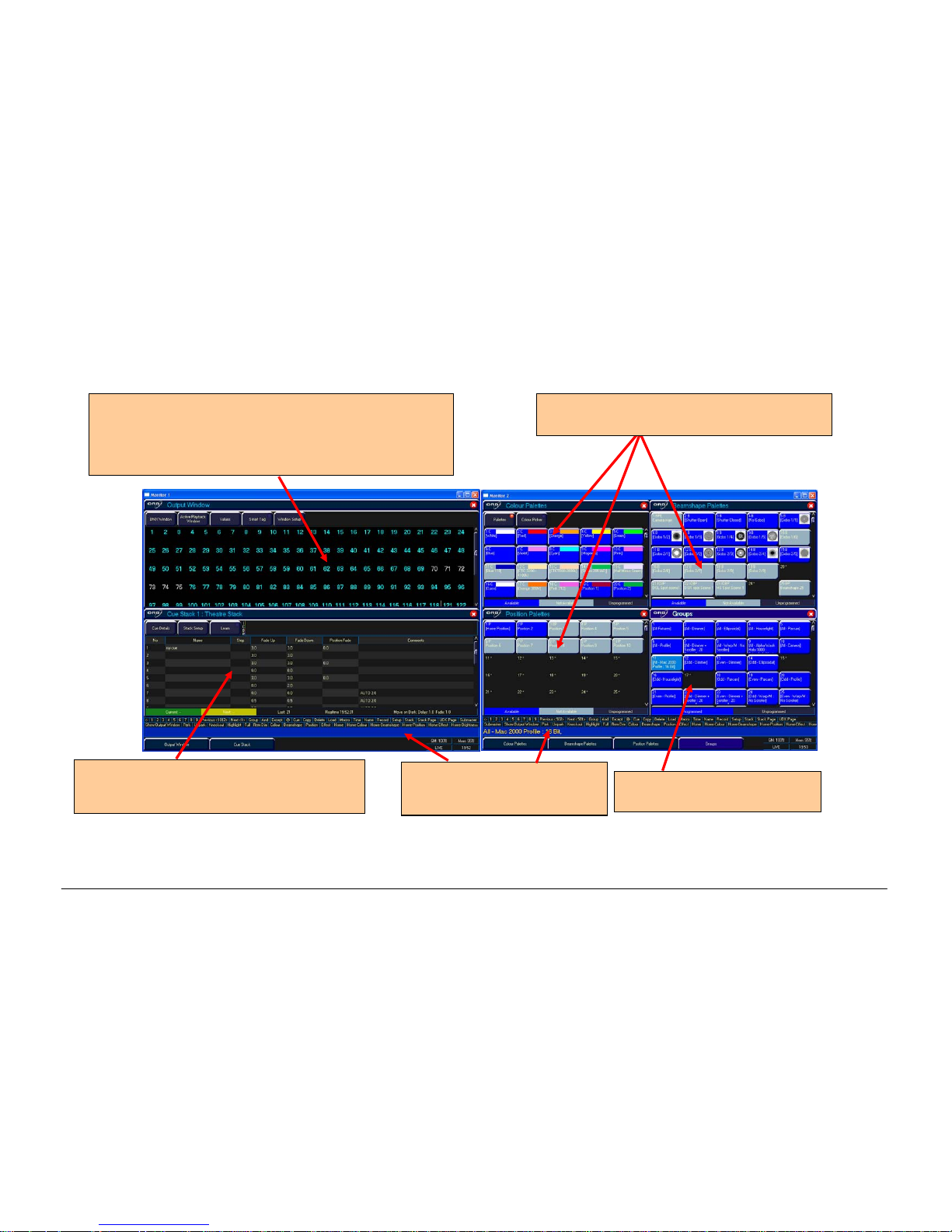
The main user interface
Figure 14 - Main User Interface
The Output Window is central to the operation the ORB
desk. It is recommended that the Output Window is
displayed on one of the monitor screens when programming
cues, palettes, UDKs etc. The colour coding also helps to
see what direction a channel has moved in.
The cue stack window shows the selected cue
stack and all the cues which that stack
contains.
The group window shows groups
of all your fixtures.
The command line shows the
commands you’ve entered on
both monitors.
The palette windows show the various recorded
palettes and can be clicked to access a palette.
Page 21

Quick Start Tutorial
ORB Operating Manual – Issue 1.0 Page 21
Controlling Dimmers
The intensity parameter of fixture(s) can be controlled by entering
commands directly via the numeric keypad or by using the
corresponding control wheel.
Intensity levels can be set for a single fixture or a number of
fixtures using the following syntax:
1 @ N ENTER
This sets the intensity output of fixture 1 to N %.
1 FULL ENTER
This sets the intensity output of fixture 1 to 100 %.
2 AND 3 @ N ENTER
This sets the intensity output of fixtures 2 and 3 to N %.
2 AND 3 FULL ENTER
This sets the intensity output of fixtures 2 and 3 to 100 %.
5 THRU 10 @ N ENTER
This sets the intensity output of fixtures 5 to 10 to N %.
5 THRU 10 EXCEPT 7 @ {wheel}
This sets the intensity of channels 5,6,8,9,10 to the level on the
wheel
5 THRU 10 FULL ENTER
sets the intensity output of fixtures 5 to 10 to 100 %.
Using the Control Wheel
The Inten
sity channel of a fixture can also be adjusted by control
wheel.
First select the fixture(s) required as described above and then use
the intensity wheel to adjust the level.
The output value is shown on the LCD screen above the
corresponding control wheel.
Tip – No Intensity Output ?
If the intensity output levels do not change when you send any of
the above commands to a fixture, or adjust the intensity level using
the wheel, check that the GRAND MASTER fader is at full and the
BLACKOUT button is off. If the selected fixture(s) have a Shutter
parameter, check that the shutter is open. Check that the Highlight
key is not selected.
Page 22

Quick Start Tutorial
Page 22 ORB Operating Manual – Issue 1.0
Controlling Fixtures
Selecting Fixtures
Fixtures are selected numerically using the number assigned to
them during the Patch Wizard. Type the fixture number(s) followed
by ENTER to select those fixtures. Fixtures are also selected if an
intensity command (above) is entered.
Homing the Fixtures
If you are unsure which fixture is which, the easiest way to see
which fixtures in the rig you are controlling is to ‘home’ them. This
will set their position (Pan and Tilt) to 50%, the dimmer to 100%
with an open white beam (no gobos or effects). The home values
can be customised in the Edit Fixtures menu in Setup.
After selecting a fixture, press the HOME key. This will send the
fixtures to its ‘home’ values and automatically tags the fixture
parameters for programming.
Controlling Fixture Parameters
Each fixture type has it’s own set of parameters (intensity, color,
gobo, pan, tilt etc. as defined in the fixture library) which are
classified or grouped together in different attributes (Position,
Colour, Beam).
Once a fixture, or group of fixtures has been selected, the attribute
buttons and control wheels can be used to adjust the parameter
output levels as required.
Controlling Colour, Beamshape and Position Parameters
The colour, beamshape and position parameters of the selected
fixture(s) are controlled using the control wheels. First select the
required fixture(s) and then press one of the attribute keys
(POSITION, COLOUR or BEAM).
The corresponding parameters for the fixture are assigned to the
control wheels and are indicated on lower part of the touch screen.
In the example below, COLOUR has been selected and the fixture
parameters Cyan, Magenta and Yellow are assigned to the three
control wheels.
If the fixture has more than three controllable parameters for the
selected attribute, pressing the attribute key selects the next group
of parameters.
Tagging Parameters
On the ORB desk, fixture parameters must be ‘tagged’ for them to
be recorded when programming cues, palettes and UDK’s.
The tag status of each fixture parameter is indicated on the LCD
screen and in the Output Window by it’s background colour – dark
background indicates that the parameter is untagged; bright
background indicates that the parameter is tagged.
If a parameter’s value is changed by a command, moving the
control wheel or directly in the Output Window, it will be tagged
automatically.
Page 23

Quick Start Tutorial
ORB Operating Manual – Issue 1.0 Page 23
Figure 15 – Output Window (Tagged & Untagged channels)
It is also possible to tag and untag fixture parameters manually by
holding down CLEAR and moving a fixture wheel, then releasing
CLEAR.
Only tagged channels will be recorded when storing a cue, palette,
UDK, etc. This gives the capability of separating your programming
between multiple UDKs, cue stacks, submasters, etc.
Cues
Once you have set up a scene that you like you can then record that
into a cue.
Selecting a Cue Stack
Cues can be programmed into any of the 1000 user programmable
cue stacks.
Press the SELECT button above the cue stack you wish to program
in. The LED in the SELECT button illuminates to indicate that it is
the active cue stack.
Recording a Cue
To record a cue, simply enter the command:
RECORD CUE n ENTER
Where N is the number of the cue you wish to record. As you have
not specified any fade times or names, the desk will enter the
default values for the cue, and the cue will be recorded.
After recording a cue, the command line is cleared, the fixtures
remain selected but the parameters are untagged.
Subsequent cues can then be set up and recorded using the same
method.
As you become more experienced with the desk, you will find the
most efficient way of programming your cues – for more methods,
see Page 85).
Note – Rec
ord Options Window
When you press the RECORD key the Record Options Window is
displayed. This window allows you to adjust what data is recorded,
as required – see the Programming chapter (Page 77) for further
details.
Tagged
Untagged
Page 24

Quick Start Tutorial
Page 24 ORB Operating Manual – Issue 1.0
Adjusting Fade and Delay Times
As well as the actual output levels recorded in the cue, each fixture
parameter also has it’s own fade and delay times.
Default fade and delay times for Intensity, Colour, Beamshape and
Position are defined in Desk Setup, and can be adjusted if required,
prior to programming cues.
Once a cue has been programmed, its times can be adjusted by
using syntax:
CUE n TIME x DELAY y {Fade} COLOUR z ENTER
Any adjusted fade times display on the monitor in the Cue Stack
window, which can also be manipulated using the cursor keys and
ENTER button in a similar format to a spreadsheet on a computer.
Naming Cues
Each cue can have a name stored alongside the cue data. Enter the
following syntax command :
CUE n NAME {your name} ENTER
Playing Back Cues
Before playing back the programmed cues in a cue stack, it is
important to clear the programmer by pressing the CLEAR button.
This removes any unrecorded commands and sends fixtures to their
default values, with the exception of the intensity, which is kept at
0%.
To play back the cues in a cue stack in sequence first select the
required page of playbacks.
Press the GO button for the selected playback, and raise the master
fader to full. These commands can be executed in either order, as
sometimes a manual fade is desirable.
Pressing the GO button will trigger the start of fades on all
parameters, but the intensity channels are mixed with the master
fader.
To output the next memory
in the stack, simply press the GO
button again. The desk will continue down the cue list, one cue at a
time. Once the end of the cue stack is reached, the first cue will be
selected as the next memory, resulting in a loop.
Once you have finished playing back cues, it is important to release
the cue stack. This returns all of the affected fixtures to their default
values, or to the value they were at before the cue stack was
executed.
Select the cue stack, using the SELECT button, then press the
RELEASE key.
Updating Cues
In order to update a cue, the first thing to do is to ensure that the
cue is outputting. If it is not outputting, enter the syntax:
CUE n GO
Once the cue is outputting, make any changes using command
syntax, fixture wheels and palettes as required.
To record the changes to the cue, press the UPDATE key. The
Update Options window will appear.
Select the cue number you wish to update in that window and press
OK. The cue will inherit the new information and the update will be
complete.
Tracking
Every cue programmed on ORB behaves in a Tracking methodology.
This means that each cue only programs the changes between two
states – channels are told to fade up, fade down, or if no
instructions are programmed, the channel will stay the same. This
is a powerful programming method as it allows advanced
Page 25

Quick Start Tutorial
ORB Operating Manual – Issue 1.0 Page 25
manipulation of the cue stack and updates can be filtered through
entire sequences without having to update each cue individually.
When updating a cue, there are four tracking options available –
Track Forward, Track Backward, Track Both or Cue Only. For a full
explanation of each of these options, see page 115).
Select
ing Cue Only forces the update only to affect the cue you are
updating.
Choosing Track Forwards allows the update to follow through in to
the following cues. If you choose to update with Track Forwards
enabled, remember to ‘undo’ the change you made in one scene
when you move to the next – particularly if the next cue is a
blackout.
Figure 16 – Update Options Window
Palettes
The ORB has four sets of 1000 palettes.
A palette is a programming tool which allows you to define the
values required in a fixture or group of fixtures to create a particular
affect on stage. For example, a palette can be stored for the colour
Red which details the DMX values required for each moving light t o
create a Red colour. Likewise a palette can be stored for a position
on the stage, with the relevant Pan & Tilt information for each
fixture in the rig.
Figure 17 – Palette Windows
Page 26

Quick Start Tutorial
Page 26 ORB Operating Manual – Issue 1.0
Recording Palettes
Programming a palette is simple and very similar to recording a cue.
Set up the fixture outputs as required, ensuring that the correct
parameters are tagged. To record the data as a colour palette, enter
the following command:
RECORD COLOUR n ENTER
To record the data as a beamshape, position or effects palette,
simply replace the COLOUR part of the above command with BEAM,
POSITION or EFFECTS.
Palette Windows
Each set of palettes has it’s own palette window. These palette
windows are displayed on Monitor 2 by default.
The palette window contains a soft button for each of the 1000
palettes. These buttons can be clicked to access a palette.
Unprogrammed palettes are indicated by a * next to the number.
Naming Palettes
As well as containing channel data, a palette can have a name
associated with it. To assign a name to a palette enter the
command:
COLOUR n NAME {your name} ENTER
These names are displayed in the palette windows and in the
command line when a palette is accessed.
Outputting Palettes
The act of outputting a palette causes the selected fixtures to move
to the value stored within that palette.
To apply or output a palette, first select a fixture or group of
fixtures
Enter the command COLOUR n ENTER
The fixture(s) will change to the colour they were in when the
palette was stored.
If any of the selected fixtures are not actually programmed in the
applied palette, but there are one or more fixtures of the same type
that are programmed, the fixture will use the values programmed
for the first fixture of the same type.
If the fixture data in the programmer is then recorded into a cue,
submaster or UDK, the desk will record the palette reference rather
than the actual parameter value. This is especially useful for
touring shows when using positions, to save updating each cue
individually.
Automatic Palettes
In Setup, there is an option to generate a set of automatic palettes
based on the fixture types in the schedule. The desk generates
palettes for a range of useful things based upon your current patch.
To create the automatic groups, first enter SETUP, press the [Auto
Menus] soft key on the monitor, select the [Create Auto Palettes]
option, then exit Setup.
Page 27

Quick Start Tutorial
ORB Operating Manual – Issue 1.0 Page 27
User Definable Keys (UDK)
The desk provides 10 user definable keys, which can be paged 20
times to give 200 programmable locations.
The user definable keys may be assigned to Groups, Individual
Fixtures, Palettes, Cues, or channel data.
Assigning User Definable Keys
In this quick start guide we will just look at recording channel data
to a UDK. For details of all the other items that can be assigned to
UDK’s see the UDK chapter (Page 100).
Set up the fi
xture outputs as required, ensuring that the correct
parameters are tagged. To record the data to a User Defined Key,
enter the following command:
RECORD <UDK>
Outputting User Definable Keys
The data assigned to a UDK is output by pressing the UDK on the
front panel or by clicking on the soft button in the User Defined
Keys Window on the monitor.
The action of the UDK can be set to either Flash or Latch in the User
Definable Keys Setup Window – see UDK section of manual (Page
100) for more information.
Groups
As well as palettes, the ORB provides 1000 user definable Groups.
Groups are most commonly used when selecting fixtures and
programming data to be recorded in cues, palettes etc. Groups can
also be assigned to User Definable Keys (UDKs).
Automatic Groups
In Setup, there is an option to generate a set of automatic groups
based on the fixture types in the schedule. The desk generates a
group for each of the types of fixtures you have, plus ‘odd’ and
‘even’ groups for each different fixture type in the schedule.
To create the automatic groups, first enter SETUP, press the [Auto
Menus] soft key on the touch screen, select the [Create Auto
Groups] option, then exit Setup.
User Defined Groups
You can create your own groups of fixtures, eg Floor MAC 700’s,
FOH MAC 700’s etc.
Simply select the fixtures that you wish to be in the group and then
enter the command:
RECORD GROUP n ENTER
Page 28

Quick Start Tutorial
Page 28 ORB Operating Manual – Issue 1.0
Group Window
The Group Window is displayed by default in the bottom right hand
corner of Monitor 2. This allows you to click and select any of the
programmed groups automatically.
Figure 18 – Group Window (bottom right)
Submasters
The ORB has upto 30 submasters, which can be paged 20 times to
give upto 600 programmable locations for scenes stored onto
faders. Submasters can be accessed either by altering the mode of
the playbacks, or by using another DMX enabled desk and using
DMX-In.
Recording Submasters
Before recording a submaster, ensure that you have the number of
submasters per page defined as you require it. This setting is found
in Desk Setup / Inputs.
To record a submaster, first set up the fixture outputs as required,
ensuring that the correct parameters are tagged. To record the data
to a submaster, enter the following command:
RECORD SUB n ENTER
To record to a specific page, enter:
RECORD SUB m / n ENTER
You can view programmed submasters in the Submasters window,
by holding SHIFT and pressing SUB.
Replaying Submasters
In this quick start guide we will just look at using DMX In to replay
submasters. For details of using Playbacks as Submasters, see the
Submasters chapter of the full manual (page 104).
In the Desk Setup / Inputs screen ensure
you have defined a DMXIn address for each of the programmed submasters. You can then
use the faders on your DMX-In desk to control the submasters.
Raising the submaster will replay the scene, and lowering it will
remove it from the outputs.
Page 29

Quick Start Tutorial
ORB Operating Manual – Issue 1.0 Page 29
Saving Shows
The ORB will save the show automatically to its internal memory at
regular intervals.
External backups of the show data can be made to a USB Storage
Device (eg the memory stick included with your ORB).
• Saving the show is done in Setup mode, so first press SETUP
• Press the [Files] key on the monitor.
• Press the [Save Show] key to enter the Save Show screen.
• Press the Destination Device key to select the required
device.
• If the device does not appear straight away, wait a few
seconds and then click [Refresh].
• Type the show name in the Filename box using an externa l
keyboard or the numeric keypad on the desk.
• Press the [OK] key.
• After a few seconds, the show will be saved.
• Press SETUP to exit Setup mode.
Saving the show takes all of the available information in the desk,
including monitor configurations, setup options, patch, cue and
palette data and stores it all into a single file on your destinat ion
device. This file can then be reloaded at a later date to return the
desk to the same state as it was in when you saved it.
Figure 19 – Save Show
Page 30

Quick Start Tutorial
Page 30 ORB Operating Manual – Issue 1.0
Loading Shows
Shows can be loaded onto the ORB from a USB Storage Device.
• Loading shows is done from within SETUP, so first press
SETUP to enter Setup.
• Insert or connect the storage medium containing the show.
• Press the [Files] key on the monitor.
• Press the [Load Show] key to enter the Load Show screen.
• Press the Source Device key to select the required device.
• A list of show files on the currently selected storage device
appears on the touch screen.
• Select the show file you wish to load using the cursor keys.
• Press [OK] key to load the show.
• The desk will load the show into its memory and you will be
returned to the home screen.
Loading a show brings back the desk to the same settings that were
defined when the show was stored – Patch information, Cue
Information, UDKs, Submasters, Palettes, Groups, Macros, Desk
Setup and Network settings will all be restored.
Figure 20 - Load Show
Page 31

Setup
ORB Operating Manual – Issue 1.0 Page 31
Setup
In Setup the ORB provides functions for configuring the desk - assigning, patching and editing fixtures, saving and loading shows, clearing
show data, resetting the desk etc.
Press the SETUP key to display the Setup Window on the monitor. The following Setup options are displayed:
Figure 21 - Setup Tabs
To select any of the other Setup options, click on the corresponding button in the Setup Window on the monitor.
To exit Setup from any of the various Setup options, close the screen that is currently displayed using the [Close] button in the top right hand
corner of the screen.
Patch – this allows
you to configure which
fixtures are assigned
to the desk. (Page 32)
Desk Setup – this allows
you to configure
behaviour, default times
and other hardware
settings. (Page 47)
Files – this allows you to load
and save shows, update
fixture libraries and view desk
information. (Page 56)
Network enables the
various Ethernet
protocols through which
ORB can communicate
with other pieces of
equipment. (Page 61)
Clear Options allows
you to delete parts of
the programming from a
single button. (Page 60)
Page 32

Setup
Page 32 ORB Operating Manual – Issue 1.0
Patch
The purpose of the Patch area of Setup is to configure the fixtures
which are connected to the desk.
The default state of ORB gives 96 dimmer channels patched 1:1 on
DMX universe 1. This means that if your rig contains 96 dimmers or
less and no other fixtures (moving lights, LED fittings, colour
scrollers, etc) then the desk is ready to go and you can skip this
section of the manual.
In order to provide optimum control of other fixtures and additional
dimmers, the desk must know several pieces of information about
the fixture, namely:
• The Manufacturer of each fixture type (eg Martin)
• The Model name for each type (eg Mac 250 Entour)
• The Mode of the fixture (eg Enhanced Mode)
• The DMX universe the fixture is connected to (eg 1)
• The DMX address the fixture is set to (eg 101)
It may be useful to collate this information into a spreadsheet (or
more likely, scribbled onto the lighting plan) before commencing the
patch on the desk, as incorrectly entered data can result in the rig
being unusable.
Adding Fixtures
Once this information is collated, you can use one of two methods
to add fixtures onto the desk.
It is possible to add fixtures using the Patch Wizard, or via Add
Fixtures. Using Add Fixtures provides maximum control of the
patch process, whereas the Patch Wizard is ideal for getting up and
running quickly. Either process has the same end result, however
you may find that one method is preferable to your operating style.
Add Fixtures
The first method of adding fixtures is through Add Fixtures. This
allows you to detail to the desk how many of each type of fixture
are contained within the rig.
Press the [Add Fixtures] button on the monitor. The Fixture
Schedule Window will appear. The left hand column in this w indow
allows you to select the fixture manufacturer from those contained
within the internal fixture library.
Scroll down or use the cursor keys to select the required
manufacturer (eg Martin). It is possible to press the “M” key on an
external keyboard to automatically jump to manufacturers
beginning with M.
Figure 22 – Add Fixtures
Page 33

Setup
ORB Operating Manual – Issue 1.0 Page 33
Press the right arrow key to move the cursor to the fixture list in
the right hand column.
Scroll down or use the cursor keys to select the required fixture
type (eg Mac 250 Entour).
Here we are detailing the quantity of fixtures found within the whole
rig, so press the ENTER key, enter the quantity of the fixture
required using the numeric keypad (eg 4), then press ENTER. The
desk then loads that number of fixtures into its memory and the
remaining control channel count will be reduced to indicate that
these channels are now allocated.
If required, you can repeat the above procedure for all the other
types of fixtures in your rig.
When you have finished adding all the fixtures you require to the
schedule, press the [OK] button in the top right.. The monitor
returns to the Patch screen.
User Fixture Types
If during the Add Fixtures process you discover that the
manufacturer or fixture type you are looking for isn’t listed, you will
require a User Fixture Type.
User Fixture Types can be created using the Fixture Tools utility
which is located on the Utilities CD provided with the desk. A guide
to creating User Fixture Types is also located on the CD.
Once a User Fixture Type has been obtained or created, to load it
into ORB you should press the [User Fixture] button in the Fixture
Schedule window.
The desk will offer you a drop down menu listing all the storage
devices detected on the USB ports. Select the drive which
corresponds to the device you have stored the fixture type on.
A list of user fixture type files found on the drive will then be
displayed and you can select the required file using the cursor keys
or trackball.
Once the file you want is highlighted, press the [OK] button to load
it into the desk.
All the fixture types contained in the selected fixture type file will be
loaded and added to the fixture library on the desk.
Selecting a user fixture type and specifying the number of that type
in the fixture schedule is carried out in the same way as for any of
the normal fixture types already present in the fixture library on the
desk.
User Fixture Types which have been loaded onto the desk are
displayed in the Fixture Schedule Window in the same way as
normal fixture types in the fixture library. They are display ed in the
correct place based on the alphabetical sorting of manufacturer and
fixture type and are distinguished by having a green background,
for example:
Figure 23 – User Fixture Types
Page 34

Setup
Page 34 ORB Operating Manual – Issue 1.0
Patching Fixtures
After adding the fixtures into the desk, the next step is to patch the
fixtures to the DMX outputs. Patching a fixture is the act of defining
on the desk which DMX channels the fixture has been set to.
Fixtures can be patched individually or in groups. Until a fixture is
patched, it will be impossible to control it on ORB, as the desk has
no information as to where within the 2048 possible channels the
data is to be sent.
DMX addresses
The DMX signal transmitted from ORB carries 512 channels of
information down each ‘universe’. Fixtures plugged into this
universe must have a DMX address set on them in order for the
desk to be able to control them.
A DMX address is the range of channels which a fixture has been
configured to respond to. This can be a single channel (for
example, a dimmer or colour scroller) or a large range (for example
a moving light). Depending on the particular equipment you are
connecting, the DMX address may be configured using DIP switches,
on-screen menus or remotely using various configuration tools. For
information on addressing your fixtures, please consult the user
manual of the fixtures.
If a fixture is using a range of DMX addreses then no other fixture in
the rig should be set to use these addresses as this will cause
problems configuring the desk to communicate with the fixtures
effectively.
A typical DMX addressing system may work like this:
1 – 96 – Dimmers 1 – 96
97 – 100 – Empty
101 – 115 – Fixture 1 (14 channels)
116 – 129 – Fixture 2 (14 channels)
129 – 143 – Fixture 3 (14 channels)
144 – 157 – Fixture 4 (14 channels)
etc
DMX universes
The ORB has four ‘universes’ of DMX output, numbered 1 to 4. Each
of these universes carries a different set of 512 channels of data,
giving a total of 2048 possible channels outputting from the desk.
There is a 5 pin XLR output for each universe, located on the rear of
the desk. Each DMX universe can also be output over Ethernet,
using various communication methods.
Using the Desk Setup / Outputs settings (Page 54) it is possible to
con
figure which DMX universe is transmitted from each of the DMX
outputs, so if the behaviour of your fixtures isn’t as you would
expect, please check these settings.
It is critical that you patch the fixtures to the correct DMX universe
to correspond with the cable which they are connected to.
Page 35

Setup
ORB Operating Manual – Issue 1.0 Page 35
Patching Fixtures
To patch fixtures at a specified DMX start address, enter the fixture
number, press the @ key, enter the DMX start address and then
press the ENTER key. For example:
1 @ 274 ENTER
This will result in the specified fixture being patched to the first DMX
universe at address 274.
Note: If you have more than one fixture with a number of 1, this
patch will patch all of these fixtures together starting with the first
alphabetically by manufacturer (eg Dimmer #1 at 274, then
AlphaSpot 300 HPE #1 at 275, then Mac 700 #1 at 307, etc). To
prevent this confusion, it is recommended to first edit the fixture
number using the Edit Fixtures screen before commencing patching
using this method. For more information, see page 43.
Patching Fixtures to a Specified Universe
Fixtures can also be patched to a specified universe by including the
universe number in the command. For example, to patch the
fixtures to universe 3 starting at DMX address 101, enter the
following command:
n @ 3/101 ENTER
If you are carrying out a lot of patching onto a specified DMX
universe, you can select it using the buttons above the patch data
in the Patch Screen – the currently selected universe is indicated
with a red indicator. Once a universe has been selected, all patch
commands which do not specify a universe will be direct to the
selected universe. By default, Universe 1 is selected.
Figure 24 – Patch Screen, Output View
Patching Composite Fixtures
Certain fixture types are composite fixtures and have to be patched
twice, once for the intensity parameter, and once for the remaining
parameters. An example of this would be the Varilite VL5, which has
an external dimmer channel in addition to the main control
channels. Another example would be a Lamp + 1 Channel Scroller
fixture which is used for patching colour scrollers.
The {Fixture Part} button on the syntax keys is used when patching
the non intensity part of the composite fixture. This syntax key
only appears where it is possible to be used, so if {Fixture Part}
does not appear then your fixture will not require composite
patching. If the fixture does require composite patching, follow
these steps:
Type in the command: 1 THRU 6 @ 101 ENTER
Page 36

Setup
Page 36 ORB Operating Manual – Issue 1.0
This will patch the intensities of the six fixtures to DMX channels
101-106 on the currently selected DMX universe. The intensity
parameter requires a single DMX channel.
Type in the command: 1 THRU 6 {Fixture Part} 107 ENTER
This will patch the remaining parameters of the six fixtures to th e
current DMX universe starting at address 107 on the currently
selected universe..
Unpatching Fixtures
Unpatching a fixture removes that fixtures information from the
DMX output, effectively disabling that fixture (although it may still
be manipulated, programmed and adjusted on the desk, no data
will be output to it).
The {Unpatch} key appears on the syntax keys when in Patch
mode. The behaviour of the Unpatch function is dependant upon
which Patch View is active at the time. For full information on Patch
Views, see page 37.
To unpatc
h a selection of fixtures from a specified universe (Outputs
or Channels view) or all universes (Fixtures view):
1 THRU 5 {Unpatch}
To unpatch an instance of a fixture from a specified universe
(Outputs or Channels view) or all universes (Fixtures view):
1 @ <address> {Unpatch}
To unpatch an instance of a fixture from a specified universe and
address (all views):
1 @ <universe>/<address> {Unpatch}
To unpatch a fixture at a specified address:
{Unpatch} <universe>/<address>
To unpatch all fixtures in a universe:
{Unpatch} <universe> ENTER
Patching a Group of Fixtures
Once programming on ORB has begun, it is possible to patch whole
groups of fixtures to DMX outputs as well. This is great for touring
productions which may have to repatch an entire part of their rig to
fit into a house rig. Group Patching is performed sequentially from
a given start address. This results in all of the fixtures of this type
being assigned one after another starting at the address you define:
Press the GROUP key, then select the group numerically. Press the
@ key, enter the DMX start address and then press the ENTER key.
For example:
GROUP n @ 1 ENTER
This will patch the entire group starting at DMX address 1 on the
selected DMX universe and increasing sequentially until the whole
group has been patched or the universe is full.
Page 37

Setup
ORB Operating Manual – Issue 1.0 Page 37
Patch Views
The Patch Window can display the patch data in three different
views on the monitor (Outputs, Fixtures and Channels). The default
view is the Outputs view (see below).
Press the [Patch View] key in the Patch Window and then select
[Outputs], [Fixtures] or [Channels] from the drop down menu. The
different patch views are described in the sections below.
Outputs View
This is the default patch view and displays the DMX start address
for each fixture for each DMX universe. The 4 universes are
displayed vertically with each fixture listed according to its outputs.
Figure 25 – Outputs View
Fixtures View
This patch view lists all the fixtures in the schedule together with
their alignment data and DMX patch address(es).
The fixtures are listed in group order. Alignment data is only
displayed if it has been changed from the defaults. Patch addresses
are displayed in the format universe/address in normal addressing
mode or simply the address in absolute addressing mode.
Figure 26 – Fixtures View
Page 38

Setup
Page 38 ORB Operating Manual – Issue 1.0
Channel View
This patch view shows the fixture type, fixture number and
parameter (eg Gobo1<>) patched to each DMX address in each of
the DMX universes, for example:
Figure 27 – Channel View
16-bit channels
The DMX protocol defines each of the 512 channels as an 8-bit level
between 0 and 255. This is sufficient for the majority of parameters
(for example, a gobo wheel may only have 7 or 8 different gobos to
select from, so 256 possible values is plenty) however in more
advanced control equipment, 256 values is not enough so two
channels are linked together to create a 16-bit channel.
These channels are paired together internally and processed as a
signal control channel. When output, the Least Significant Byte
(Fine channel) is faded between 0 and 255, then returned to 0 as
the Most Significant Byte (Course) is increased by 1, then the
pattern continues. This process gives 65536 possible values for a
channel instead of the 256 possible using 8-bit control.
In Channel View, the acronyms MSB and LSB are used to describe
Most Significant Byte (Course) and Least Significant Byte (Fine)
channels of 16-bit parameters.
Page 39

Setup
ORB Operating Manual – Issue 1.0 Page 39
Patch Wizard
The Patch Wizard guides you through the entire patching process,
and is a faster way of getting a simple patch up and running than
using Add Fixtures and Patching through syntax. However, the
Patch Wizard makes the assumption that your rig has been patched
sequentially and can be slower for complicated patch entry.
To use the Patch Wizard, press the [Patch Wizard] button on the
monitor. The Patch Wizard will appear and guide you through
adding some fixtures.
Figure 28 – Patch Wizard (Step 1 – Manufacturer Selection)
First the wizard allows you to select the fixture manufacturer.
Scroll down or use the cursor keys to select the required
manufacturer (eg MARTIN). If you have a keyboard connected, you
can press the M key to jump straight to manufacturers beginning
with M.
Standard Dimmers can be patched using the <Standard Fixtures>
type, which is also where you will find fixtures such as RGB
Dimmers (for LEDs), Scrollers and Relays.
Press the [Next] button to move to the next step.
Figure 29 – Patch Wizard (Step 2 – Fixture Selection)
Scroll down or use the cursor keys to select the required fixture
type (eg MAC 700 Profile).
Page 40

Setup
Page 40 ORB Operating Manual – Issue 1.0
Press the [Next] button to select the fixture Mode. It is important
that the mode set here matches the mode set on the fixture itself –
if in doubt, consult the fixture operating manual for full details.
Figure 30 – Patch Wizard (Step 3 – Mode Selection)
Once the Mode has been selected, press the [Next] button to move
on and enter the DMX address for the fixture. If you have not yet
set this on the fixtures themselves, press the [Next Address] button
and the desk will calculate a DMX address for you based on the
existing patch information.
It is important here to ensure that the DMX universe is correctly
selected.
Figure 31 – Patch Wizard (Step 4 – DMX Address entry)
Once the address is configured, press the [Next] button and enter
the quantity of the fixture required. The monitor screen will tell you
the number of fixtures and control channels remaining within its
limits, to ensure you do not exceed these limits.
Page 41

Setup
ORB Operating Manual – Issue 1.0 Page 41
Figure 32 – Patch Wizard (Step 4 – Quantity)
The final step in the Patch Wizard is to assign a fixture number to
the fixtures. The fixture number is the number you will refer to the
fixture as within the desk software. It is recommended that you
take some time thinking about numbering your fixtures. Enter the
number and press [Finish].
The Patch Wizard is now complete and your fixtures have been
assigned. If everything has gone according to plan, the fixtures
should now have moved to their Home positions.
You can repeat the Patch Wizard for every group of fixtures you
have.
Page 42

Setup
Page 42 ORB Operating Manual – Issue 1.0
Editing Fixtures
Edit Fixtures allows you to carry out various functions relating to the
fixtures assigned to the desk, including :
• Name individual fixtures
• Assign user fixture numbers
• Edit fixture parameter Default (release) values
• Edit fixture parameter Home values
• Edit fixture parameter Topset values
• Adjust the Pan and Tilt alignment of fixtures
• Patch Functions
The behaviour of each of these functions is described in this
chapter.
To enter Edit Fixtures, press the [Edit Fixtures] button on the
monitor. The Edit Fixtures screen is then displayed.
To make changes to a particular fixture or a group of fixtures, first
select the fixture group by pressing the GROUP button repeatedly
until the required group is displayed in the title bar. All the fixtures
in this group are now displayed in the Edit Fixtures window.
Press the [Default], [Home], [Topset] etc button to display the
required data. Use the cursor keys to move to the individual field to
edit or use the ALL row to select the value for all fixtures in the
group. Press ENTER to enter the field, adjust the value as required,
then press the ENTER key.
Figure 33 - Edit Fixtures
Once all changes have been made, press the [OK] key to return to
the Patch screen.
If you make a mistake in Edit Fixtures, or simply wish to revert to
the original values from the fixture library then press the [Reset All]
key. If you wish to cancel all editing of the fixtures, press the
[Cancel] key.
Page 43

Setup
ORB Operating Manual – Issue 1.0 Page 43
Fixture Numbers
Each fixture on the desk has its own fixture number, which is the
number it will be referred to during programming and on-screen.
Initially, these fixture numbers are set to increase sequentially
starting from 1 within the their type, eg Dimmers 1 - 48, MAC 700s
1 - 20, MAC 2000s 1 - 20, etc. If you have used the Patch Wizard
then you will have already altered these numbers as part of the
process. If, however, you have used Add Fixtures then you can
alter these numbers if required.
It is recommended that you take some time thinking about
numbering your fixtures. It is useful to renumber your fixtures to
something logical and unique, as this will be how each fixture will
then be referenced during programming and playback. A fairly
common numbering system is to prefix each fixture type with a
unique number, so for example:
Dimmers 1 - 48 remain as fixture numbers 1 – 48.
MAC 700’s 1 - 20 become fixture numbers 701 – 720.
MAC 2000’s 1 - 20 become fixture numbers 201 – 220.
To renumber a complete group of fixtures, the ALL row can be used.
Use the arrow keys to move the cursor to the ALL row and No
column and then press the ENTER key. Enter the fixture number for
the first fixture in the group and press ENTER.
Example: Select the MAC 700 group and enter 501 in the ALL row
and No column. The MAC 700 fixtures will be renumbered 701, 702,
703 etc.
Notes – Fixture Numbers
If a fixture number is not
globally unique, ie another fixture exists
with the same fixture number in a different type, then a ‘*’ is
displayed after the fixture number.
If you have patched using the Patch Wizard then the Fixture
Numbers will automatically have been set as part of the patch
process. If you have used Add Fixtures then you will need to define
a unique number for the fixture.
Naming Fixtures
The Fixture name defaults to the fixture type (eg MAC 700).
Fixtures can be renamed by the user, if required (eg Stage Left MAC
700, Centre Stage MAC 700, Stage Right MAC 700).
Use the arrow keys to move the cursor to Name column and then
press the ENTER key. Enter the name of the fixture using the
external keyboard, then press ENTER.
Editing Default, Home & Topset Values
The Default values for fixture parameters are the values that are
output when the fixture is released.
The Home values for fixture parameters are the values that are
output when the fixture is homed or highlighted.
The Topset value for each parameter is the maximum value which
can be reached when adjusting the fixture using the wheels,
command line, etc. This is set to a default value of 100%.
The initial values for all of these settings are initially taken from t he
fixture profile data stored in the fixture library in the desk. They are
set to values that will produce an open white beam (no gobos or
effects) at a central position (Pan and Tilt at 50%).
These values can be edited on an individual fixture or group basis as
required.
First, select the required tab (Default, Home or Topset).
Page 44

Setup
Page 44 ORB Operating Manual – Issue 1.0
Now, use the arrow keys to move to the required column of the
selected fixture and then press the ENTER key.
Enter the required value using the external keyboard or numeric
keypad on the front panel of the desk, then press ENTER.
Aligning Fixtures
The ORB desk is capable of making adjustments to your fixtures to
take into account their rigging position.
Inverting Pan and Tilt
It
is possible to invert Pan and Tilt independently for each fixture.
This can be particularly useful if you’ve rigged Front of House
fixtures the opposite way around to those onstage.
Use the arrow keys to move the cursor to the Invert P or Invert T
column of the required fixture and then press the ENTER key. Use
the left and right arrow keys to toggle between the values Yes and
No. Select the required value and then press the ENTER key
Now any adjustments you make to the parameter you changed will
be inverted in the DMX outputs, making all your fixtures move in
the same direction relative to the wheels.
Swapping Pan and Tilt
If a fi
xture is rigged on its side, you may also wish to Swap the Pan
and Tilt parameters. In this function, any values defined for Pan
will be output on the Tilt channel(s), and any values defined for Tilt
will be output on the Pan channel(s).
Use the arrow keys to move the cursor to the P/T Swap column of
the required fixture and then press the ENTER key. Use the left and
right arrow keys to toggle between the values Yes and No. Select
the required value and then press the ENTER key.
Patch Functions
The Patch functions under Edit Fixtures allow you to patch, repatch
and unpatch selected fixtures. This functionality is provided in
addition to the command line patching detailed elsewhere in this
chapter. Using this window, it is possible to patch a fixture to more
than one DMX address in one or more universes. These additional
patch addresses are known as duplicates.
Select the fixture(s) to be edited. Click on the [Patch] button in the
Edit Fixtures Window.
Figure 34 - Edit Fixtures (Patch)
Page 45

Setup
ORB Operating Manual – Issue 1.0 Page 45
The patch table shows the DMX-In assignment (if assigned) and the
DMX address(es) that each of the selected fixtures are currently
patched to. If a fixture has not yet been patched to the DMX output
then the corresponding DMX column will show ‘Add’. In the
example above – Fixture numbers 101 to 105 are patched to DMX
universe 2 address 1, 13, 25, 37 and 49 respectively.
Patching Fixtures
Move the c
ursor to the DMX column for the required fixture and
press the ENTER key. A Patch Fixture(s) popup window is displayed
on the monitor screen, for example:
Figure 35 - Edit Fixtures (Repatching)
Select the required Universe by clicking on the [Universe] button
and selecting the universe from the drop down menu.
Enter the required DMX address in the Address field provided or
press the [Next Address] button to automatically pick up the next
available patch address in the selected universe.
Press the [OK] button to complete the patching operation or the
[Cancel] button to cancel.
Repatching Fixtures
Move the c
ursor to the DMX or Duplicate n column for the required
fixture and press the ENTER key. The Patch Fixture popup window
is displayed on the monitor screen with the current patch address in
the DMX Address field
Select the required Universe by clicking on the [Universe] button
and selecting the universe from the drop down menu.
Enter the required DMX address in the Address field provided or
press the [Next Address] button to automatically pick up the next
available patch address in the selected universe.
Press the [OK] button to complete the patching operation or the
[Cancel] button to cancel.
Unpatching Fixtures
Move the c
ursor to the DMX or Duplicate n column for the required
fixture and press the ENTER key. The Patch Fixture(s) popup
window will be displayed on the monitor screen with the current
patch address in the DMX Address field.
Press the [Unpatch] button. A confirmation popup window will be
displayed. Select the [Yes] button to confirm the operation.
Adding Duplicates
Move the cursor to th
e Duplicate 1 column for the required fixture
and press the ENTER key. The Patch Fixture popup window is
displayed on the monitor screen.
Select the required Universe by clicking on the [Universe] button
and selecting the universe from the drop down menu.
Enter the required DMX address in the Address field provided or
press the [Next Address] button to automatically pick up the next
available patch address in the selected universe.
Press the [OK] button to complete the patching operation or the
[Cancel] button to cancel.
Page 46

Setup
Page 46 ORB Operating Manual – Issue 1.0
To patch further duplicates for the selected fixture move the cursor
to the Duplicate 2 Column, Duplicate 3 column etc and repeat the
above procedure.
When duplicates are patched for the selected fixture(s) additional
columns are added to the Edit Fixtures table (one column per
duplicate address) as shown in the following example:
Figure 36 - Edit Fixtures (Duplicates)
Multi-Part Fixtures
F
or multi-part fixtures (eg Lamp + Scroller) the different parts of
the fixture are displayed on separate lines in the Edit Fixtures patch
table.
There is an additional column (Part) which shows the part name of
the multi-part fixture and a [Fixture Part] button that selects which
part of the fixture is displayed on the screen (eg All Parts, Lamp,
Scroll).
Figure 37 - Edit Fixtures (Multi Part fixtures)
DMX In Field
It is possib
le to assign a DMX-In address to any fixture on ORB.
The DMX-In field in the patch table shows the DMX In address
which is currently assigned to the fixture.
The DMX In channel is used to control the brightness (intensity)
parameter of the fixture, and is mixed LTP with the level on the
desk so you can grab and alter the level of a channel in such a way
as you would expect on a generic fader based desk.
Page 47

Setup
ORB Operating Manual – Issue 1.0 Page 47
Clicking on an entry in the DMX In column allow s you to chan ge the
DMX In address assigned to the corresponding fixture.
Figure 38 - Entering a DMX In Address
Changing Fixture Type (Fixture Swapout)
Thi
s patch function allows you to swap one fixture type for another.
This function allows for a complete swap-out of fixtures from one
type to another. The desk will attempt to clone the programmed
data for the swapped fixture(s) in Cues, UDKs, Submasters and
Palettes as far as possible.
Parameters in the new fixture type that were not present in the
original fixture type are left unprogrammed.
Select the fixture(s) to be changed. Go to the [Type] column in the
window.
Select the [Change] button for the required fixture or the [Change]
button in the ALL row to change the type of all the selected fixtures.
Select the Manufacturer, Fixture Type and Mode (if applicable) using
the popup window on the monitor and confirm the change type
operation.
Auto Menus
This Setup option generates automatic items based on the fixture
schedule.
Auto Groups
This function generates a group for each of the types of fixture, plus
‘odd’ and ‘even’ groups for each different fixture type in the desk.
Press the [Auto Menus] key on monitor in the Patch tab.
Select the [Create Auto Groups] option from the drop down menu.
Figure 39- Creating Auto Groups
Page 48

Setup
Page 48 ORB Operating Manual – Issue 1.0
Auto Palettes
When the [Create Auto Palettes] option is confirmed the desk
generates a number of colour, beamshape and position palettes for
each moving fixture type in the fixture schedule and a number of
standard effects palettes, as described below.
Colour Palettes
The desk provides the following standard colour palettes: White,
Red, Orange, Yellow, Green, Blue, Violet, Cyan, Magenta and Pink.
Fixtures with colour wheel(s) - The desk compares the RGB values
specified for each colour on the colour wheel of the fixture with the
RGB values of the standard colours listed above. The desk
generates an auto palette for those which are within a certain
tolerance of the standard colour.
In addition
to the above, the desk generates an auto palette for
each colour available on every colour wheel in the fixture. These
palettes are labelled with the stock colour names as supplied by the
manufacturer.
Fixtures with CMY or RGB colour mixing – The desk generates auto
palettes for all
of the standard colours listed above.
Beamshape Palettes
The beamshape auto palettes generated by the desk are based on
the gobo wheel and shutter parameters of the fixture in the
schedule as follows:
Gobo Wheel(s) – An auto palette for each Gobo present on each
gobo wheel in the fixture. Naming syntax is Gobo 1/1 … Gobo 1/N
(first gobo wheel), Gobo 2/1 .. Gobo 2/N (second gobo wheel etc.
No Gobo – This auto palette sends all the ‘Gobo’ parameters to
their default values.
Shutter - Two auto palettes (Shutter Open and Shutter Closed).
Position Palettes
The desk generates a single Home Position palette which sets the
Pan and Tilt parameters to a value of 50%.
Effects Palettes
The desk generates a number of standard effects (see Effects
chapter for details).
Auto Macros
When the [Create Auto Macros] option is confirmed the desk
generates a number macros based upon the fixture types patched.
These macros often include Lamp On, Lamp Off and Reset
commands.
Page 49

Setup
ORB Operating Manual – Issue 1.0 Page 49
Desk Setup
The Desk Setup function allows you to configure or customise the settings on the desk to your own requirements. The Desk Setup function is
divided into a number of different sections which are accessed by pressing the corresponding soft button on the monitor.
Figure 40 - Desk Setup
Displays - Indicate which
monitors are connected;
adjust the screen timeout,
brightness and contrast;
calibrate touch screens;
ad
j
ust desk lamp brightness.
Peripheral – Adjust the
sensitivity of the wheels on
the desk
Inputs – Set up SMPTE and MIDI
Timecode; CAN; Set Time; Set Date.
Assign Remote Switches & Submaster
DMX Inputs
Outputs – Configure
DMX universes to
DMX out
p
ut sockets.
Behaviour – Keep
parameters separate
options; Confirm
Overwrites.
Default Times – Set up the
default delay and fade times
for each attribute (Intensity,
Colour, Beamshape,
Position) for all new
Cue Stack Defaults – Set
up default options for all new
cue stacks including
timecode and chase
Submaster Defaults – Set
up default options for all new
submasters.
Page 50

Setup
Page 50 ORB Operating Manual – Issue 1.0
Displays
Press the [Displays] button on the monitor, and then choose the required option from the monitor. The options are detailed below:
Figure 41 - Desk Setup / Displays
Monitor Display 1
Enabled - Yes or No.
Monitor Display 2
Enabled - Yes or No.
Colour Scheme – allows
you to pick which colour
scheme to use.
Screen Timeout – Sets
the time till the monitors
and LCDs go into power
save mode.
LCD Brightness & Contrast
– Sets the brightness and
contrast for the LCDs on the
front panel. This can also
be set by holding down
SETUP and moving the
wheels.
Monitor Calibration –
Activates touchscreen
calibration for each monitor.
LCD Font Size – Sets the
font size the LCD displays
use.
Page 51

Setup
ORB Operating Manual – Issue 1.0 Page 51
Touchscreens
A number of external touchscreens are supported by the ORB. These screens connect into the desk using the USB connection. Screens with a
serial connection will not work via a USB-Serial converter. The screen needs to have a direct USB connection. It is recommended only to
purchase one of the known working screens from the list below, for use with your ORB.
Currently known working
(tested and confirmed)
ZerOS version 5.0.0
Currently assumed working
(driver support provided, no reports)
Not yet working
3M Microtouch M150
3M Microtouch M170
ELO ET1746L
LG L1730SF
LG L1530SF
iPure
Solarism LM1731BT
ELO touch (most)
3M/Microtouch EX II series
ITM
eTurboTouch (non-eGalax compatible)
Gunze AHL61
DMC TSC-10/25
eGalax, eTurboTouch CT-410/510/700
PanJit
LG Touch (all)
Ilyama
Solarism LM1730S
ELO Touch Acoustic Pulse Recognition
(APR)
screens
Although we will endeavour to add support for other screens where possible, we make no guarantees about this since the drivers may not be
available in the correct format for the desk operating system. If you want us to add support for a different screen, then we may ask you to loan
us the screen (including the drivers CD that came with it) for a short time for testing. Please contact Zero 88 for details.
Page 52

Setup
Page 52 ORB Operating Manual – Issue 1.0
Peripheral
Press the [Peripheral] key on the monitor. The various options are shown on the monitor.
Figure 42 - Desk Setup / Peripheral
Wheel Sensitivity –
Adjusts the sensitivity of
the control wheels. 0%
is least sensitive, 100%
is most.
Page 53

Setup
ORB Operating Manual – Issue 1.0 Page 53
Inputs
Press the [Inputs] key on the monitor. The various options are shown on the monitor.
Figure 43 - Desk Setup / Inputs
MIDI Timecode – The
frame rate of the MIDI
timecode being fed to
the desk, in fps.
Remote Switches - Each of
the six remote switches can be
configured to Disabled, Go to
Cue or Macro.
If the action field is set to Go
to Cue or Macro, then an
additional field is displayed
allowing you to enter the
stack/cue or macro number as
appropriate.
CAN – Not yet
implemented in
software
Set Date - Press the [Set Date] key on the monitor.
The Set Date Window is displayed. Enter the correct
Day, Month and Year in the fields provided and then
confirm by selecting the [OK] button.
Submasters Per Page –
The number of submasters
you require on each page.
Defaults to 10.
Submaster DMX
Address – The DMX –IN
address you will use to
control each submaster.
SMPTE Timecode –
The frame rate of the
SMPTE timecode being
fed to the desk, in fps.
Set Time - Press the [Set
Time] key on the monitor.
The Set Time Window is
displayed. Enter the correct
time in the field provided and
then confirm by selecting the
[OK] button.
Page 54

Setup
Page 54 ORB Operating Manual – Issue 1.0
Outputs
Press the [Outputs] key on the monitor. The various options are shown on the monitor:
Figure 44 - Desk Setup / Outputs
• DMX Output 1
• DMX Output 2
• DMX Output 3
• DMX Output 4
Each DMX Output Universe can be
mapped to a different Data
Universe. The default setting is a
1:1 mapping.
Page 55

Setup
ORB Operating Manual – Issue 1.0 Page 55
Behaviour
Press the [Behaviour] button on the monitor. The various options are shown:
Figure 45 - Desk Setup / Behaviour
Keep Parameters Separate –
If the options above are set to
‘Yes’ then each individual
parameter in that attribute will be
tagged separately (eg in a CMY
fixture, if Cyan is adjusted, only
Cyan will be tagged).
If the attribute is set to ‘No’ then
as soon as one parameter in that
attribute is adjusted, all the
parameters in that attribute will
be tagged automatically (eg in a
CMY fixture, if Cyan is adjusted,
then Cyan, Magenta, Yellow and
any other colour parameter for
the fixture will be tagged
automatically).
Confirm Overwrites When this option is set to
‘Yes’ a confirmation
window will appear on the
monitor when overwriting
a cue, palette, effect,
macro etc.
Recovery Mode – This
setting defines how the
desk behaves when
powered up – Restart
from Last State or
Blackout.
Page 56

Setup
Page 56 ORB Operating Manual – Issue 1.0
Default Times
Press the [Default Times] key on the monitor. The various options are shown:
Figure 46 - Desk Setup / Default Times
Intensity Fade /
Delay – Separate times
for channels fading Up
and those fading Down.
Colour Fade / Delay – The
times that colour channels
use when programmed into
cues or UDKs
Beamshape Fade / Delay
– The times that beamshape
channels use when
programmed into cues or
Position Fade / Delay –
The times that position
channels use when
programmed into cues or
Page 57

Setup
ORB Operating Manual – Issue 1.0 Page 57
Cue Stack Defaults
Press the [Cue Stack Defaults] key on the touch screen. The various options are shown on the touch screen under four main sections (General,
Chase, Trigger and Move on Dark):
Figure 47 - Desk Setup / Cue Stack Defaults
General Options:
Timecode – Default
Timecode setting
Master Fader –
Default Master Fader
mode
Trigger Options:
Trigger on Raise – Default
Trigger on Raise setting
Trigger Level – Default Level
Move on Dark Options:
Move on Dark – Default
Enabled or Disabled
Delay – Default Delay time
Fade – Default fade time
Chase Options:
Chase Drive – Default Drive
for a stack turned into a chase
Chase Direction – Default
Direction for a stack turned
into a chase
Chase Speed – Default Speed
Chase Fade – Default Fade %
Chase Shots – Default # of
Shots
Page 58

Setup
Page 58 ORB Operating Manual – Issue 1.0
Submaster Defaults
• Not Yet Written
Lock Functions
Press the [Lock] key on the touch screen. A drop down menu is
displayed on the touch screen. The menu options are summarised
below:
• Lock All – This option locks all
the functionality on the desk. It
will not be possible to do anything on the desk until it is
unlocked using the current lock code.
• Change PIN – This option allows the user to change the lock
code (PIN) for the desk. The lock code (PIN) is a four digit
number (0000 – 9999). The lock code can be entered via the
numeric keypad on the front panel, or external keyboard. The
default lock code for the desk is 0000.
• Cancel – Closes the menu.
If you forget the lock code for your ORB, please contact Zero 88
Technical Support for assistance and have the desk’s serial number
to hand. You may be asked some questions to verify your identity
and ensure that you have a genuine reason to unlock a desk
without knowing its lock code.
• This functionality is not yet implemented in software
Page 59

Setup
ORB Operating Manual – Issue 1.0 Page 59
Files
This section of Setup allows you to save and load show files and to
load or clear User Fixtures (UFTs). Each section of the Files menu is
accessed through a button on the monitor.
Saving Shows
To save a copy of your show, you first need a storage media. The
ORB is supplied with a 1GB USB flash memory stick, although other
storage media may be used with the console. Connect your media
to the USB port on the desk (any port will do). If using an external
floppy drive, remember to insert a floppy disk into the drive.
Press the [Files] button on the monitor.
Press the [Save Show] button on the monitor. The Save Show
window is displayed:
Figure 48 - Save Show
• Select the desired storage device by pressing the
[Destination Device] key. This cycles through all the
available devices; select the one you require. If the drive
doesn’t appear in the list, press [Refresh] after a couple of
seconds.
• Select the Filename field and enter a name for the show file.
This name will be used as the file name on the destination
device, so ensure it is unique and easily identifiable.
• Select the [Save Complete Show] box and toggle it until it
displays the option you require. The ORB allows you to save
just the Setup, the Setup and Palettes, or the Complete
show.
• Press the [OK] button to save the show.
Page 60

Setup
Page 60 ORB Operating Manual – Issue 1.0
Loading Shows
To load a show, connect the storage media to the USB port on the
desk (any port).
If you’re using an external floppy drive, remember to insert the
floppy disk into the drive.
Press the [Files], then [Load Show]. The Load Show Window is
displayed:
Figure 49 - Load Show
Select the storage device by pressing on the [Source Device] toggle
box. This will cycle through all the available devices, so select the
one you require.
Select the required show from the list of available shows displayed.
Select the [Load Complete Show] box and toggle it until it displays
the option you require. The ORB allows you to load just the Setup,
the Setup and Palettes, or the Complete show.
Press the [OK] button to load the show.
Note – Loading Shows
Loading a show file will clear any existing show data from the desk
so ensure that you have backed up your previous show before
you
load another one onto the desk.
Page 61

Setup
ORB Operating Manual – Issue 1.0 Page 61
Loading User Fixture Types
The desk provides a method for loading fixture types which are not
in the fixture library stored on the desk, ie user fixture types which
are stored on a memory stick or CD.
Press the [Load User Fixtures] key in files.
Select the Source Device (Removable Device) as required. A list of
UFT files found on the source device is displayed on the touch
screen.
Select the required file using the cursor keys or by touch on the
touch screen.
Select the [OK] button.
Figure 50 - Loading a user fixture
All the fixture types contained in the selected UFT file are loaded
and effectively added to the fixture library on the desk.
Selecting a user fixture type and setting the number of that type in
the fixture schedule is performed in the same way as for any of the
normal fixture types already present in the fixture library on the
desk.
User Fixture Types which have been loaded onto the desk are
displayed in the Fixture Schedule Window in the same way as
fixture types in the fixture library. They appear in the schedule
based on the alphabetical sorting of manufacturer and fixture type
and are distinguished by having a green background, for example:
Figure 51 – User Fixture Types in Add Fixtures
Page 62

Setup
Page 62 ORB Operating Manual – Issue 1.0
Clearing User Fixture Types
The desk provides a method for clearing all the user fixture types
which have been loaded onto the desk.
Press the [Clear User Fixtures] button on the monitor. A
confirmation window is displayed.
Press the [Yes] button to clear the user fixtures which have been
loaded on the desk.
Update Fixture File
The desk software includes the latest fixture library release at the
time the software was released. From time to time a new software
release is made. This option allows you to update the Fixture
Library file on the desk.
Insert a memory stick containing the Fixture Library file into one of
the USB ports on the desk.
• Press SETUP
• Press the [Files] button
• Press the [Update Fixture File] button.
• The desk searches for the update file on the memory stick.
• Follow the instructions shown on the monitor to complete the
update.
Desk Information
When the [Desk Information] key is selected a screen is displayed
containing information on the various software, firmware and BIOS
installed in the desk as follows:
• Hardware Platform
• Slave 1 Bootloader
• Slave 1 Firmware
• Slave 2 Bootloader
• Slave 2 Firmware
• Motherboard BIOS
• NVR Location
• OS Version
• Software Version
• Serial Number
• Fixture Library
• Current Show
• Flash Size
If any versions are displayed in RED in the Desk Information screen,
this indicates that the versions are out of date. Please contact a
Zero 88 service agent for advice on updating these software
versions.
When reporting any problems to Zero 88, please include all of the
information displayed within the Desk Information screen.
Page 63

Setup
ORB Operating Manual – Issue 1.0 Page 63
Clear Options
This option allows the user to clear (delete) various components of a show (eg palettes), the whole show, or reset the desk back to factory
defaults.
Press the [Clear Options] key on the Setup screen. The various clear options and other functions are displayed on the monitor as shown below:
Figure 52 - Clear Options
Clear Colour Palettes
… Clear User Defined
Keys - Clears the
specified items only
from
the show data in the
desk.
Clear All – Clears all of
the above items from the
show in the desk, but
does not
clear the Patch
or change any of the
Setup options.
Reset Desk –
Performs the Clear
All operation, clears
the Patch and resets
all the Setup options
to factory defaults.
Page 64

Setup
Page 64 ORB Operating Manual – Issue 1.0
Network
The ORB supports various Ethernet communication protocols, for connecting to visualisation tools, PDA remote controls, etc. Details of these
protocols are found in this section:
Ethernet Basics
Unlike DMX, Ethernet operates in a different topology. DMX is da isy
chained from fixture to fixture, whereas Ethernet data is connected
using a Star topology.
IP Addresses
IP Addresses are a devices identity on an Ethernet network.
The address indicates where the device is located and in
combination with the Subnet Mask, indicates what the desk
can see, and vice-versa. The number is made up from 4
blocks of data, between 0 and 255 – eg 192.168.0.1
Subnet Masks
The Subnet Mask indicates what a network device can see on
the network – the standard subnet mask for an Ethernet
network is 255.255.255.0, indicating that a device with an IP
address of 192.168.0.1 can see any device whose IP starts
with 192.168.0.x, but cannot see anything starting
192.168.1.x
Page 65

Setup
ORB Operating Manual – Issue 1.0 Page 65
Changing an IP Address
On Windows XP, to configure the IP
address of a PC, first select Start,
Connect To, Show All Connections…
Find the connection for the Network
Adaptor you want to use (usually
“Local Area Connection”) and right
click on it, selecting “Properties”.
Select the “Internet Protocol (TCP/IP)” and press Properties
Enter the required IP address
settings in the popup window and
select OK.
Switch vs Crossover
There are two ways of making an Ethernet connection with a
ZerOS console
Via a standard Ethernet Switch – the desk is connected to
one connector on the switch, and other devices are
connected to another port
Via a crossover cable – the desk and connected device are
connected together directly via a crossed network cable.
This system is ideal for visualisation PCs as it negates the
need for an additional box in the middle, however this
system has its drawbacks – it is not possible to use DHCP
configuration, and it is not possible to connect more than
one device in this manor.
DHCP
DHCP is a protocol used by Ethernet enabled devices to
dynamically allocate an IP address to devices on the
network. In order to use this system, a DHCP host must
exist on the network. Some Ethernet Switches offer DHCP
capabilities, as do Wireless Routers. It is important that you
ensure that there is only ONE DHCP host on a network –
multiple DHCP hosts can cause malfunctioning of the system.
Page 66

Setup
Page 66 ORB Operating Manual – Issue 1.0
Art-Net
Art-Net is a lighting protocol which sends DMX data over Ethernet. The standard
allows for multiple DMX universes to be sent over a single Ethernet cable. The
ZerOS consoles can output upto 4 universes of DMX data via Art-Net.
Each Art-Net device needs an IP address starting with a 2.x.x.x or a 10.x.x.x, and
this setting must match on the desk itself. Each DMX universe must then be
allocated to a Port – Art-Net Ports numerate from 0-15, so it is generally
accepted that desk universe 1 will become Art-Net universe 0, however this is
user definable.
Art-Net enabled devices include Media Servers, Moving Lights and also dedicated
DMX output boxes such as the “1 Universe Ethernet Box” by Cooper Controls.
The system will look something like this:
Transmit Art-Net - Enables or
Disables ArtNet transmission.
Network Switch - 2 or 10.
ArtNet allows two separate
network IP ranges.
Each port can be allocated a
separate port, or be disabled.
This port must be matched with the
Art-Net receiving device (Light
Converse, etc).
Light Converse Integration Allows additional functionality to
be used with Light Converse (eg
bi-directional patching, fixture
selection etc.)
Subnet - The y number in
the 2.x.y.z IP range.
Used for multiple Art-Net
networks on a single network.
Page 67

Setup
ORB Operating Manual – Issue 1.0 Page 67
Remote
ZerOS Remote offers the ability to remotely control various areas of
the desk. The remote uses a standard Windows Mobile or Windows
PocketPC application to enable remote control of the console via a
wireless network.
The ideal setup for this system is as follows:
The console is connected to a Wireless Router via an Ethernet
connection. The Wireless Router is then configured to enable
wireless communication via a standard 802.11b connection, and the
Palmtop Computer (PDA) connects to this wirelessly. As long as the
console IP address and the PDA IP address are able to see each
other, the system should automatically setup and configure.
With a PC connected to the network with the desk and the PDA,
load up an internet browser and type in http://192.168.0.1/
(or the
configuration IP address of the router, if different) into the address
bar and hit GO.
At this point you will be prompted for a user name and password,
which will be detailed in the user manual for the router.
Once connected to the router, look for settings which relate to the
wireless connection and to DHCP. Ensure that DHCP is enabled and
that the wireless is active. Setup a name for the wireless network
which you'll recognise (we use "Zero 88") and choose a wireless
channel. If required, security can be added. Once settings have
been changed, click the Save Option and then the Reboot Router
option to ensure that the settings are stored.
Ensure that the PDA has activated the wireless connection (this is
normally done through some sort of connection manager). The first
time you enable wireless in an area, the PDA will search for all
available wireless networks and will ask you if you want to connect
to any it finds. At this stage, you should see the Zero 88 network
listed. Select it and choose connect (if you added security, you'll
need to enter these details here).
Once the PDA is connected and the desk is connected, on the desk
go to Setup / Network / Remote. Choose Enabled Remote - Yes, and
Use DHCP Address - Yes. Again, enable security if you like (this
security is simply a password the remote will prompt you for before
connecting).
At the bottom of the remote setup screen, a message should appear
- "Remote Active". If "Remote Not Active - No DHCP Address" is
displayed, ensure that DHCP is enabled on the router and reboot the
desk.
Assuming "Remote Active" is displayed and the PDA connected to
the wireless network, you should be able to start the ZerOS Remote
program on the PDA and the desk should be detected. Press on the
Desk name and click the connect button.
For full information on the Remote, see the Remote chapter in this
manual (Page
115).
Page 68

Setup
Page 68 ORB Operating Manual – Issue 1.0
Light Converse (http://www.lightconverse.net)
The Light Converse visualiser uses Art-Net to communicate with the
desk software, hence the presence of the visualisation configuration
settings in the Art-Net tab of Network Setup. The rules of Art-Net
(above) apply when configuring a Light Converse setup.
Light Converse integration requires a Zero 88 Light Converse USB
dongle, available from Zero 88. Once active, the system allows
bidirectional control of fixtures, selection and patching via the
Ethernet connection.
Capture (CITP) (http://www.capturesweden.com)
Capture 2005 visualising software communicates with the desk via a
protocol known as CITP. This protocol allows for any standard PC
network between the desk and the visualising PC. The console
allows you to configure either a fixed IP address or one allocated via
DHCP. As long as the two devices can see each other, the system
should function correctly.
Page 69
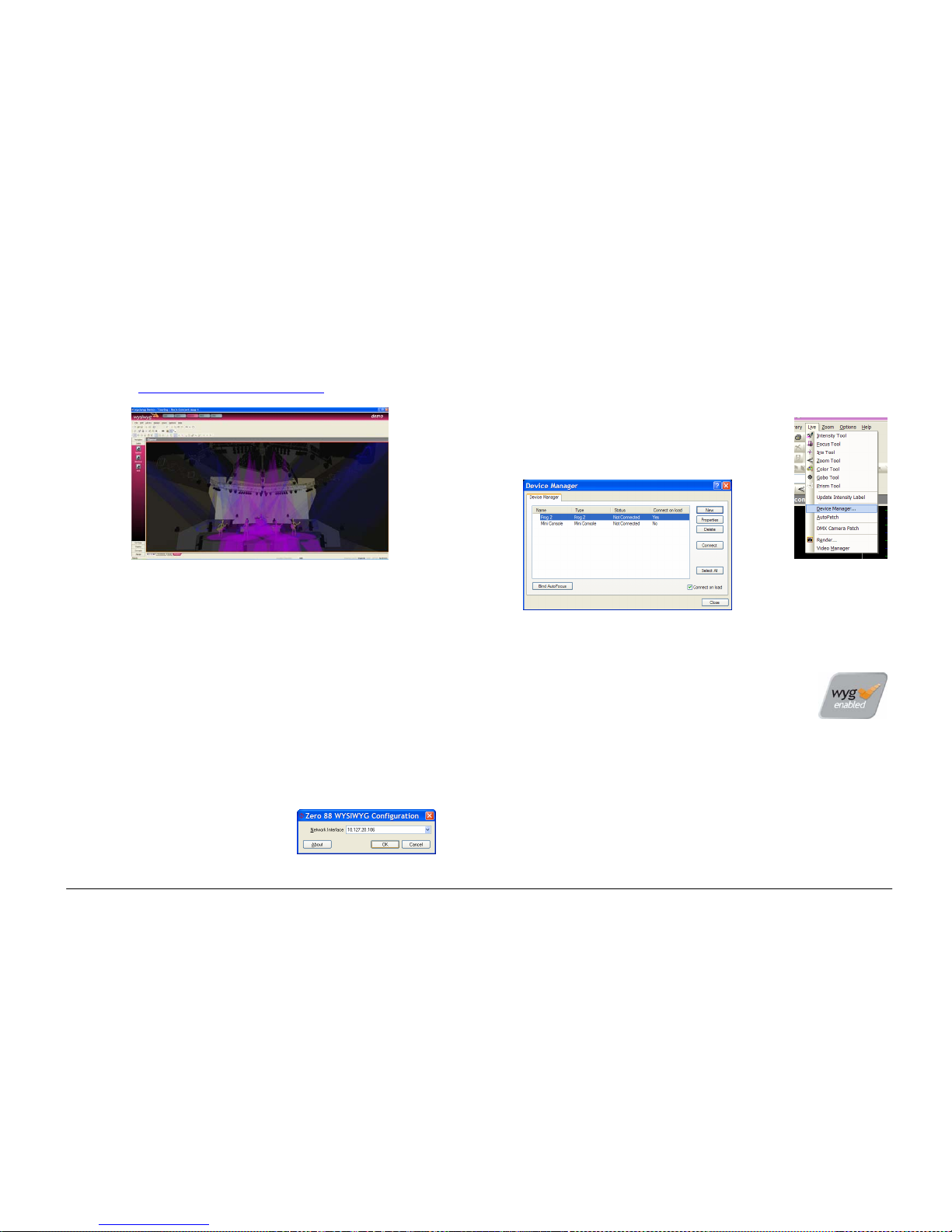
Setup
ORB Operating Manual – Issue 1.0 Page 69
WYSIWYG (http://www.castlighting.com)
WYSIWYG Requirements
• A current (Release 21 or greater) installation of WYSIWYG
Perform
• The Zero 88 consoles file (provided on the Cast website)
• The Zero 88 WYSIWYG Driver (provided on the Zero 88 website,
or on the CD with the desk)
• An Ethernet connection to your Zero 88 console
WYSIWYG Installation
• First install WYSIWYG Release 22 or greater, following the
standard procedure (if you’re using Release 21, you’ll need the
Zero 88 Consoles CFB file)
• Run the Zero 88 WYSIWYG Driver installation tool
• Once the driver is installed, run the tool
• Select the network interface you wish to connect WYSIWYG with
(the IP address is shown)
• Choose OK
WYSIWYG Usage
• Start WYSIWYG & load your show file
• Patch your fixtures to Universes in WYSIWYG
• In the LIVE tab, select LIVE, Device Manager
• In Device Manager, select New and locate the
Zero 88 console you are connecting to
• Select the console and click Properties, then enter the IP
address of the desk in the Address. Select each Port on the
desk and Bind these to a Universe on WYSIWYG.
Page 70

Setup
Page 70 ORB Operating Manual – Issue 1.0
• In the Device Manager, click
CONNECT and the console should
connect. You can now use WYSIWYG
to visualise your show.
• When you have finished using it,
click DISCONNECT in the Device
Manager.
Zero Wire
Zero Wire DMX is a wireless DMX transmission system from Zero
88. The system can be output directly from the console via the
[Network] options in Setup, and can then be routed via a Wireless
Access Point to Zero Wire DMX boxes which decode the signal to
DMX for linking to fixtures and dimmers, etc.
In the Zero Wire setup page there are a host of options, which
enable each DMX Universe on the desk to be routed to an IP
address with a unique Universe number (see below).
For more information, see the Zero Wire DMX user manual, which
can be found on the Zero 88 website.
Page 71

The Output Window
ORB Operating Manual – Issue 1.0 Page 71
The Output Window
The Output Window is central to the programming functionality on the ORB desk. It is recommended (but not mandatory) that the Output
Window is displayed on one of the monitor screens when programming cues, palettes etc. To display the Output Window, press the {Show
Output Window} syntax key.
Values – allows you
to select between
values, fade, delay
and source views
Window Setup –
allows you to
customise the window
to your requirements.
Fixture names
Channel information –
colour coded
Blue – Fading Up
Green – Fading Down
Red – In Programmer
Orange – In Programmer but
untagged
Yellow Background – Selected
Red Background - Parked
White – From a Cue
Yellow – From a UDK / Sub
Selected Channels
Selected fixture information.
One row for each fixture, one
column for each parameter.
Gobo previews appear here.
Page 72

The Output Window
Page 72 ORB Operating Manual – Issue 1.0
The Output Window displays the outputs which are coming from
all areas of the desk (Programmer, Cue Stacks or UDK’s). The
outputs can be viewed as DMX values, Percentage values or
parameter Details, and can show Values, Fade or Delay times per
channel.
Output Window – Values View
In the Output Window, when the [Values] option is selected, the
fixtures and their parameter values are shown. The currently
selected fixtures are highlighted in yellow. Fixture parameters which
are tagged have a bright background, untagged parameters have a
dark background. This is the Normal view of the Output Window.
Output Window - Fade View
When the [Fade] option is selected, the fade times of the fixture
parameters are displayed in the Output Window, and the fixture
wheels can be used to adjust the fade time of their relevant
parameters.
Output Window - Delay View
When the [Delay] option is selected, the delay times of the fixture
parameters are displayed in the Output Window. Like Fade view, the
fixture wheels can be used to adjust the timing of a parameter.
Figure 53 - Output Window Fade View
Output Window – Source View
When the [Source] option is selected, the Output Window displays
the source of the output data rather than the actual output values
as follows:
o P Programmer
o C S/C Cue (Stack Number / Cue Number)
o SX/Y Submaster (Page Number / Submaster)
o UDK p/n User Defined Key (Page / Number)
o PARKED The fixture has been parked
o D Default value of the parameter
Output Window – Window Setup
Pressing the Window Setup button opens a popup window which
allows you to adjust the Output Window configuration.
Page 73

The Output Window
ORB Operating Manual – Issue 1.0 Page 73
Figure 54 - Output Window Setup
Details (%)
Wh
en the [Details (%)] soft button is selected a drop down menu is
displayed with the following options:
• Percent – When this option is selected all the fixture parameter
values are displayed as percentages (ie 0 – 100% for both 8 bit
and 16 bit parameters).
• DMX - When this option is selected all the fixture parameter
values are displayed as DMX values (ie 0 - 255 for 8 bit
parameters or 0 - 65535 for 16 bit parameters).
• Details (%) – When this option is selected the fixture
parameter values will be displayed as the parameter detail
names (eg Red, Gobo 1) where they are defined in the fixture
data. If parameter details are not defined, the window will show
the actual numerical values in %.
• Details (DMX) – When this option is selected the fixture
parameter values will be displayed as the parameter detail
names (eg Red, Gobo 1) where they are defined in the fixture
data. If parameter details are not defined, the window will show
the actual numerical values in DMX (0-255 or 0 – 65535).
Hide Unpatched
The Hide Unpatched option allows you to hide any non-outputting
channels. This cleans up the output view but may hide information
you require if you are offline programming a show before patching
the desk. Gaps in numbers are indicated by a vertical line between
their channel numbers.
Figure 55 - Output Window (Hide Unpatched)
Channel / Fixture / Intensity Views
There are three different views of the Output Window (Channel,
Fixture and Intensity). Click on the [Channel] button and select the
required view from the drop down menu.
Fixture view is useful for moving light heavy rigs as it details all of
the moving light parameters all of the time, whereas Channel View
only shows the selected fixtures parameters.
Page 74

Programming
Page 74 ORB Operating Manual – Issue 1.0
Programming
This section of the manual covers the basic functionality of programming which involves selecting fixtures, adjustin g one or more of their
parameters to the required values, and then recording the information into a cue, palette, effect or UDK.
Selecting Fixtures
Before fixtures can be controlled by the desk they need to be
selected. Selected fixtures are shown with Yellow backgrounds in
the Output window.
To select an individual fixture or a number of fixtures, type in their
fixture numbers followed by ENTER, for example:
1 ENTER (selects fixture 1)
2 AND 3 ENTER (selects fixtures 2 and 3)
5 THRU 10 ENTER (selects fixtures 5,6,7,8,9, and 10)
For example, if the MAC 700’s have been given fixture numbers 701
– 720, then the following commands could be used:
701 ENTER (selects the first MAC 700 fixture)
702 AND 703 ENTER (selects the second and third MAC 700)
711 THRU 720 ENTER (selects the last 10 MAC 700 fixtures)
Alternatively, you can use the syntax keys to select the next or
previous fixture respectively.
Controlling Intensity Parameters
The intensity (or brightness) parameter of the selected fixture(s)
can be controlled by entering commands directly via the numeric
keypad or by using the control wheel.
Intensity levels can be set for a complete group of fixtures using the
following commands:
GROUP n @ m ENTER
(sets the intensity output to m %)
Intensity levels can also be set for a single fixture or a number of
fixtures within a group. First select the group and then use any of
the following commands:
1 @ N ENTER
(sets the intensity output of fixture 1 to N %)
1 FULL ENTER
(sets the intensity output of fixture 1 to 100 %)
1 @.
(sets the intensity output of fixture 1 to 0%)
2 AND 3 @ N ENTER
(sets the intensity output of fixtures 2 and 3 to N %)
2 AND 3 FULL ENTER
(sets the intensity output of fixtures 2 and 3 to 100 %)
5 THRU 10 @ N ENTER
(sets the intensity output of fixtures 5 to 10 to N %)
5 THRU 10 FULL ENTER
(sets the intensity output of fixtures 5 to 10 to 100 %)
The Intensity channel of a fixture can also be controlled using the
intensity wheel.
Use the control wheel to adjust the intensity level as required. The
output value is shown on the LCD sceren above the wheel. Note
that intensity adjustment on the wheel is relative by def ault which
means that if a range of fixtures are selected with different original
values, the movement of the wheel will be applied to each fixture
Page 75

Programming
ORB Operating Manual – Issue 1.0 Page 75
individually (eg each fixture will increase or decrease by a
percentage from its original value).
Note – Intensity on the Wheel
The Intensity wheel will always control the selected fixtures
intensity.
Note – No Intensity Output ?
If the intensity output levels do not change when you send one of
the above commands to a fixture, or adjust the intensity level using
the wheel, check that the GRAND MASTER fader is at full and the
BLACKOUT button is off. If the selected fixture(s) have a Shutter
parameter, check that the shutter is open.
Some fixtures also have control of the lamp remotely – try sending
the Lamp On macro command to the fixture, if supported.
Controlling Fixture Parameters
Each fixture type has it’s own set of parameters (intensity, colour,
gobo, pan, tilt etc.) which are classified or grouped together in
different attributes (Position, Colour, Beam). This information is
defined in the fixture library.
Once a fixture, or group of fixtures has been selected, the attribute
buttons and control wheels can be used to adjust the parameter
output levels as required.
Controlling Colour Parameters
The colour parameters of the selected fixture(s) are controlled using
the control wheels.
First select the required fixture(s) and then press the COLOUR key.
The colour parameters for the fixture are assigned to the control
wheels and are indicated on the LCD screen above the wheels.
If the fixture has more than three controllable parameters for the
selected attribute, pressing the COLOUR key again will select the
next group of parameters.
Wherever possible the desk will group similar parameters together
(eg Cyan, Magenta and Yellow will appear together on the wheels).
Adjustment of colour is by default an Absolute adjustment.
Controlling Beamshape Parameters
The beamshape parameters of the selected fixture(s) are controlled
using the control wheels.
First select the required fixture(s) and then press the BEAM key.
The beamshape parameters for the fixture are assigned to the
control wheels and are indicated on the LCD screen above the
wheels.
If the fixture has more than three controllable parameters for the
selected attribute, pressing the BEAM key will select the next group
of parameters.
Adjustment of beamshape is by default an Absolute adjustment.
Controlling Position Parameters
The position parameters of the selected fixture(s) are controlled
using the control wheels.
First select the required fixture(s) and then press the POS key.
The position parameters for the fixture are assigned to the control
wheels and are indicated on the LCD screen above the wheels.
If the fixture has more than three controllable parameters for the
selected attribute, pressing the POS key will select the next group
of parameters.
Adjustment of position is by default an Absolute adjustment.
Page 76

Programming
Page 76 ORB Operating Manual – Issue 1.0
Tagging Parameters
On the ORB desk, fixture parameters must be ‘tagged’ for them to
be recorded when programming cues, submasters, palettes and
UDK’s.
The tag status of each fixture parameter is indicated on the LCD
screen and in the Output Window by it’s background colour as
follows: dark background = untagged; bright background = tagged.
Figure 56 - Output Window showing tagged channels
If a parameter’s value is changed by a command, moving the
control wheel or directly in the Output Window, it will be tagged
automatically.
You can also tag and untag fixture parameters manually by holding
down CLEAR and moving a wheel.
Smart Tags
There is a [Smart Tag] button displayed in the Output Window and
on the front panel of the desk:
Figure 57 - Smart Tag button
In normal desk operation, only those channels which are tagged in
the programmer will be recorded into the cue, submaster, UDK or
palette.
Smart Tags remove the need for you to work out which channels
should or shouldn't be tagged in a state. As such, they can be used
to build states using submasters and other playback elements.
When the RECORD key is pressed the state on stage is what will be
recorded, regardless of whether or not a dimmer channel or fixture
parameter is tagged in the programmer.
Put simply, with Smart Tags enabled, you no longer have to th ink
about Tracking. The desk will insert whatever tracking is required
to make your show work - including ignoring fixtures whose
intensity is set to 0% to enable Move on Dark to fully function.
To switch on Smart Tags – click on the [Smart Tag] button in the
Output Window, or press the SMART TAG button on the front panel.
Use Smart Tags in combination with Cue Only to create inserted
cues that don't affect the rest of the cue stack, for example an
added blackout in the middle of a scene.
Page 77

Programming
ORB Operating Manual – Issue 1.0 Page 77
The Command Line
All commands (selection commands, intensity commands, wheel
movements, manual tagging etc) are recorded and displayed on the
command line, found at the bottom of the monitor.
The commands may be undone, one at a time using the backspace
key () on the numeric keypad. Each press of the backspace key
undoes one command until you reach the original group selection
command.
Figure 58 - Command Line
Above the Command Line on the monitor is the Suggested
Commands bar, which follows your syntax commands and shows
you the buttons which can be pressed next in your syntax. These
command buttons either exist on the front panel or syntax keys, or
are hidden shortcut commands (eg Rem Dim, which is SHIFT and
FULL)
Basic Record Commands
Once a scene is set up in the programmer as you require it, it can
be recorded to a cue using the following syntax:
RECORD CUE n ENTER
(Records cue N in the selected cue stack)
RECORD SUB n ENTER
(Records submaster N on the current page)
RECORD x/y ENTER
(Records cue Y on cue stack x)
RECORD SUB x/y ENTER
(Records submaster Y on page X)
By following this simple record logic, you can program most simple
items. The syntax also follows through for palettes and groups:
RECORD COLOUR n ENTER
(Records the colour parameters to the specified palette)
RECORD GROUP n ENTER
(Records the selected channels into a group)
RECORD <UDK>
(Records the outputting data onto a UDK)
For full details about recording and playback of each programmable
element, see the relevant pages later in the manual.
After Programming
After programming it is critical that you CLEAR the programmer
before playback. Any remaining parameters trapped into the
programmer will affect your outputs and what you see will not be as
you programmed it until such a time as you clear the programmer.
Double press the CLEAR button and then replay your cues or
submasters as required.
Clear
As soon as any changes are made to the outputs in the
programmer, the LED in the CLEAR key is lit, to indicate that fixture
parameters have been changed.
Pressing the CLEAR key once clears all the commands in the
command line except for the fixture selection.
Pressing the CLEAR key a second time clears the fixture selection
from the programmer.
It is important to clear your programmer before playing back your
show to ensure that what you have programmed is what you see on
the outputs.
Page 78

Updating
Page 78 ORB Operating Manual – Issue 1.0
Updating
Update Options Window
After setting up data in the programmer and pressing the UPDATE
key, or after loading an item (cue, palette, submast er or UDK) into
the programmer, adjusting parameter values or times and pressing
the UPDATE key, the Update Options Window is displayed on the
touch screen and both monitor screens.
The Update Options Window contains a number of soft keys that
allow you to select what, how and where the information will be
updated. This window is very similar in both style and operation to
the Record Options Window. Example:
Figure 59 - Update Options
Source Options
The top section of the window contains one or more source option
buttons. There is a soft button for each source that may be updated
by the user. Each source may be independently selected or
deselected by pressing the soft button. When a source is not
selected the button is grey. When a source is selected the button is
green.
In the case where an item (cue, palette, submaster or UDK) has
been loaded into the programmer, parameter values or times
adjusted and the UPDATE key pressed, the Update Options
Window contains the loaded item as the only source option. This
option is automatically selected.
Show All Button
By default, the source options displayed in the Update Options
Window are restricted to those items that have channels affected by
the changes made in the programmer.
If the [Show All] button is selected, all the currently outputting
sources, regardless of channel ownership will be displayed, allowing
you to update items that did not previously have control of the
updated channels in the programmer.
Tracking Options
Below the source options section there is a row of buttons
containing the tracking options [Track Forward], [Track Backward],
[Track Both] and [Cue Only]. These options are only applicable and
accessible when a cue (or cues) are selected.
These four options are mutually exclusive, with the default option
being [Track Forward]. When an option is selected the button turns
Page 79

Updating
ORB Operating Manual – Issue 1.0 Page 79
green. The tracking options work in the same way as they do in the
Record Options Window (page 116).
Merge and Remove Options
These two buttons allow you to merge or remove the specified data
in the programmer from existing
cues, palettes or UDKs. These
two buttons are mutually exclusive.
If [Merge] is active, the data will be merged into the selected cue,
palette, submaster or UDK.
If [Remove] is active, the data will be removed from the selected
cue, palette, submaster or UDK.
Clear Tagging
This button determines what happens to the parameters in the
programmer after the update operation is performed.
If the [Clear Tagging] button is active then the parameters will be
untagged
after the update operation.
If the [Clear Tagging] button is inactive then the parameters will
remain tagged after the update operation.
Attribute Selection Bar
The Attribute Selection Bar indicates which parameters will be
recorded for each of the different attributes (Intensity, Position,
Colour, Beamshape and Effects).
When the Update Options Window is displayed - the attribute
selection bar initially shows red (tagged) for each attribute in which
one or more parameters of that attribute are tagged in the
programmer and grey (none) for those attributes where no
parameters are tagged.
Pressing each of the soft buttons cycles round the three options for
that attribute. The current option is indicated by the background
colour of the button as follows:
Grey = No Parameters; Green = Tagged Parameters; Red
= All Parameters.
OK and Cancel Buttons
Press the [OK] button to update the selected source options.
Press the [Cancel] button to close the Update Options Window
without updating any items.
Page 80

Groups
Page 80 ORB Operating Manual – Issue 1.0
Groups
The ORB provides 1000 user definable Groups. Groups are most
commonly used when selecting fixtures and programming data to
be recorded in cues, palettes etc. Groups can also be assigned to
User Definable Keys (UDK).
What are Groups?
Groups on ORB are lists of channels which are similar in some way,
and are commonly used for speeding up programming. For
example, groups may be created for the Warm generic wash, all
Front of House moving lights, all On Stage Moving Lights, etc.
Having groups created before commencing programming of cues
speeds up the creation of the cues as instead of having to
remember a list of channels, you only have to remember one group
number.
Automatic Groups
In Setup, there is an option to generate a set of automatic groups
based on the fixture types in the schedule. The desk generates a
group for each of the Master Groups, plus ‘odd’ and ‘even’ groups
for each different fixture type in the schedule.
To create the automatic groups, first enter SETUP, then press the
[Auto Menus] button and select the [Create Autogroups] option,
then exit Setup.
Automatic Groups are referenced by Group Number and appear in
the Group Window.
User Defined Groups
In addition to the Automatic Groups, you can also create your own
groups of fixtures, eg Floor MACs, Left Stage Movers etc. User
defined groups can be all of the same fixture type or any
combination of fixture types.
Simply select the fixtures that you wish to be in the group and then
enter the command:
RECORD GROUP n ENTER
RECORD {click on a group in the Group Window}
The specified group will then be stored.
Naming Groups
Each group can have a name associated with it – this name is then
displayed in the Group window and command line when accessing
groups.
To set the name of a user defined group, select the required group
from the Group Window and press the NAME key or enter one of the
following commands:
GROUP n NAME {your name} ENTER
NAME GROUP n ENTER
Type in the name of the group using the external keyboard and
then press ENTER.
Copying Groups
To create a copy of a group, enter the following command:
GROUP n COPY TO p ENTER
This will create a copy of the original group (n) at location (p) which
you can use or modify as required.
Page 81

Groups
ORB Operating Manual – Issue 1.0 Page 81
Moving Groups
If you need to re-order your groups, you can Move a group from
one location to another. Enter the following command:
GROUP n MOVE TO p ENTER
Deleting Groups
To delete a group, enter one of the following commands:
GROUP n DELETE
DELETE GROUP n ENTER
The desk will ask you to confirm this action before the command is
executed. Once deleted, a group cannot be recovered but can be
recreated manually if required.
Group Window
The Group Window appears on Monitor 2 in the bottom right by
default.
To display the Group Window on the monitor, hold down the SHIFT
key and then press the GROUP key:
Figure 60 – Group Window
The Group Window contains a soft button for each of the 1000
groups. Each soft button contains the following data: Group Number
(1-1000) and name, if defined.
Unprogrammed groups are indicated by a ‘*’ next to the group
number.
Page 82

Palettes
Page 82 ORB Operating Manual – Issue 1.0
Palettes
The ORB desk provides you with four sets of 1000 palettes. The
palettes are stored under the nominal headings of Position, Beam,
Colour and Effects.
Palettes may contain any combination
of Intensity, Colour,
Beamshape, Position or Effects parameters. For example, a colour
palette may include intensity and colour, a beamshape palette could
include beamshape and position etc.
What are Palettes?
Palettes on ORB are small pieces of information which define to the
desk how to create a particular look on stage. For example,
palettes may be created for colours Blue, Red and Yellow, positions
Downstage Left, Centre Stage and Upstage Right, and beamshapes
Gobo 3, Prism In, Rotation, etc. Having palettes created before
commencing programming of cues speeds up the creation of the
cues as instead of having to continuously move the fixture wheels
to adjust parameters, you only have to enter the palette reference.
Recording Palettes
Programming a palette is simple and similar to recording a cue. Set
up the fixture outputs as required, ensuring that the correct fixture
parameters are tagged, and then enter the following command:
RECORD COLOUR n ENTER
To record the fixture data as a beamshape, position or effects
palette, simply replace the COLOUR part of the command with
BEAM, POSITION or EFFECTS respectively.
Hints on Recording Palettes
If you wish to record attributes, other than the default one for the
type of palette being recorded, then select the required attributes
on the Record Options Window on the monitor before
pressing the
ENTER key.
When creating Position palettes, use Highlight (SHIFT + HOME) key
to grab a fixture in open white. Set the position as required, then
turn the Highlight off before recording the palette. This way you
won’t have to untag the intensity of each fixture.
Naming Palettes
Palettes can be named, either as a separate operation or as part of
the recording process, by entering one of the following commands:
COLOUR n NAME {your name} ENTER
NAME COLOUR n ENTER {your name} ENTER
RECORD COLOUR n NAME {your name} ENTER
Outputting Palettes
Select a fixture or group of fixtures and then enter one of the
following commands:
COLOUR n ENTER
Snaps the outputs to the programmed palette values.
COLOUR n TIME x ENTER
Fades the outputs in X seconds.
If any of the selected fixtures are not actually programmed in the
applied palette, but there are one or more fixtures of the same type
that are programmed, the fixture will use the values programmed
for the first fixture of the same type.
If the fixture data in the programmer is then recorded into a cue or
UDK, the desk will record the palette reference number rather than
the actual parameter values.
Page 83

Palettes
ORB Operating Manual – Issue 1.0 Page 83
Updating Palettes
It is possible to update palettes in several ways. The first option is
to load that palette back into the programmer. Enter the syntax:
LOAD COLOUR n ENTER
Now make the changes to the palette as required (by adjusting
parameters as required) and then press UPDATE. The Update
Options window will appear:
Figure 61 - Update Options
The palette you loaded will automatically be selected, so you just
need to press OK to complete the edit.
The other option for updating palettes is to do the update without
first loading the palette. When you press UPDATE you will be
offered a number of sources – select the one you wish to update
and press OK.
Copying Palettes
To copy a palette from one location to another, enter one of the
following commands:
COLOUR n COPY TO p ENTER
BEAM n COPY TO p ENTER
POSITION n COPY TO p ENTER
EFFECTS n COPY TO p ENTER
As all palettes have the same data structure and may contain
fixture parameter data from any combination of attributes, it is also
possible to copy a palette from one attribute to another, for
example:
COLOUR 2 COPY TO BEAM 5 ENTER
Moving Palettes
To Move a palette from one location to another, enter one of the
following commands:
COLOUR n MOVE TO p ENTER
BEAM n MOVE TO p ENTER
POSITION n MOVE TO p ENTER
EFFECTS n MOVE TO p ENTER
When a palette is moved to a new location, any cues that
referenced the original palette will now reference the new location
of the palette.
As all palettes have the same data structure and may contain
fixture parameter data from any combination of attributes, it is also
possible to move a palette from one attribute to another, for
example:
COLOUR 2 MOVE TO BEAM 5 ENTER
Deleting Palettes
To delete a palette, enter one of the following commands:
COLOUR n DELETE
DELETE COLOUR n ENTER
BEAM n DELETE
Page 84

Palettes
Page 84 ORB Operating Manual – Issue 1.0
DELETE BEAM n ENTER
POSITION n DELETE
DELETE POSITION n ENTER
To delete a range of palettes, enter the following command:
DELETE COLOUR a THRU b ENTER
When a palette is deleted, any cues that previously referenced the
palette are updated to contain the actual values that were stored in
the palette.
Palette Windows
Each set of palettes has it’s own palette window. To display one of
the palette windows on the monitor, hold down the SHIFT key and
then press the appropriate attribute key (POSITION, COLOUR,
BEAM or EFFECTS).
The palette window contains a soft button for each of the 1000
palettes. Each soft button contains the following information:
Palette Number, content flags that indicate the attributes that are
programmed in the palette and a name.
The Palette Windows appear on Monitor 2 by default, with the
exception of the EFFECTS Palettes window which must be opened if
required.
Figure 62 –Palette Windows (Monitor 2)
Page 85

Cues, Stacks & Pages
ORB Operating Manual – Issue 1.0 Page 85
Cues, Stacks and Pages
The ORB provides a total of 1000 user programmable Cue Stacks.
Each of these 1000 cue stacks, can be programmed with up to 999
cues.
An entire Cue Stack can be converted to run as a Chase, if required.
There are 100 pages of playbacks available. Each page contains 10
playbacks.
The 100 pages of playbacks are automatically assigned to the 1000
cue stacks in numerical order (ie Page 1 contains cue stacks 1 – 10,
Page 2 has cue stacks 11 – 20, up to Page 100 which has cue
stacks 991 – 1000).
Cues
The Cue is the basic element for storing fixture parameter levels
and times, which can then be played back via a number of different
mechanisms.
Cues are recorded into memory stacks (or stacks) and may also be
assigned to User Defined Keys (UDK) as required.
A cue may be numbered from 1 – 999. You can also insert up to 99
cues between each whole cue number (eg 1.1, 1.2, 1.3 … 1.99 may
be inserted between cues 1 and 2).
Cues are referenced by their stack number and cue number
separated by a ‘/’ (eg 1/1 is stack 1 cue 1, 2/3 is stack 2 cue 3,
23/12 is stack 23 cue 12).
Cues can be triggered by a number of different methods (GO
button, automatically after a specified wait time, Real Time, SMPTE
Time, MIDI Time, CD Time or macro).
Cues may contain macros which are run automatically when the cue
is triggered.
Cues may also be named, edited, copied, removed and deleted.
Programming Cues
Once you have set up a look that you like, by selecting fixtures and
adjusting their parameters as described in the previous chapters,
you can then record that state into a cue. To see the cues being
recorded it is recommended that the Cue Stack Window is
displayed on one of the monitor screens. See page 88 for more
in
formation.
Selecting a Cue Stack
Cues on the ORB can be programmed into any of the 1000 cue
stacks.
Select the required page using the STACK PAGE button, eg STACK
PAGE 1 ENTER.
Press the Stack SELECT button (1-10) above the cue stack you wish
to program. The LED in the SELECT button is lit to indicate that it is
the active cue stack, and the Cue Stack Window changes to show
the cues programmed in that stack.
Recording a Cue
Having selected a cue stack into which to program your cues, as
described above, ensure that your stage look is correct and all the
required fixture parameters have been tagged.
Page 86

Cues, Stacks & Pages
Page 86 ORB Operating Manual – Issue 1.0
To record the tagged parameters into the next available cue on the
selected cue stack, simply enter the following command:
RECORD ENTER
To name the cue at the time of recording simply enter the
command:
RECORD SET <enter name of cue> ENTER
If you wish to record the fixture data to a particular cue in the
selected stack, rather than the next available cue, then enter the
following command:
RECORD (CUE) N ENTER (N = Cue Number, CUE is optional)
If you wish to record the fixture data to a particular cue stack and
cue number, rather than the next available cue on the selected
stack, then enter the following command:
RECORD S/C ENTER (S = Stack No, C = Cue Number)
After recording a cue, the command line is cleared, the fixture
parameters are automatically untagged, but the fixtures remain
selected.
Subsequent cues can then be set up and recorded in a similar way.
As you become more experienced with the desk, you will find the
most efficient way of programming cues into cue stacks.
Note – Programming Cues
The ORB desk operates primarily as a tracking console. This means
that if a parameter is programmed in one cue, it will track through
all subsequent cues until it is programmed to do something else. If
you program cue stacks sequentially, you shouldn’t have to worry
too much about tracking, as long as you ensure that you tag any
parameters you wish to be recorded in the cue you are working on.
For more information on Tracking, see page
116.
Naming Cues
Enter the command CUE n NAME or NAME CUE s/c ENTER. The Edit
Cue Name popup is displayed on the touch screen (see below). Type
in the required name using the external or on-screen keyboard and
then press the [OK] button to complete.
Figure 63 - Naming Cues
It is also possible to name a cue at the same time as it is being
recorded by entering the following command: RECORD CUE n
NAME
Editing Cue Output Levels
In order to edit a cue you first need to load it into the programmer,
by entering the following command:
LOAD CUE n ENTER
This loads the cue into the programmer and outputs the
programmed DMX values. You can then select fixtures and make
changes to the parameter output levels as necessary, in the same
way as when recording the cue initially (see earlier).
Page 87

Cues, Stacks & Pages
ORB Operating Manual – Issue 1.0 Page 87
To record the changes to the same cue press the UPDATE key.
The Update Options Window is displayed – see page 78 for more
det
ails.
Editing Cue Fade and Delay Times
Editing fade times and delay times is carried out in the same way as
editing the cue output levels, ie load the cue into the programmer,
adjust the times as necessary, then record the data back into the
cue using the UPDATE key – see previous section.
The fade and delay times can also be globally
edited from the Cue
Stack Window. Select the fade up, fade down, or attribute fade
field in the window, press the ENTER key, enter the required time(s)
and then press ENTER to complete.
Fade Time Commands – Recording Cues
When recording a cue - fade times can be specified in the command
syntax for all fixture parameters, individual attributes or
combinations of attributes as follows:
RECORD (CUE) S/C TIME X ENTER
Sets the fade times for all fixture parameters to X
seconds.
RECORD (CUE) S/C TIME U/D ENTER
Sets the intensity fade up and fade down times to U
and D seconds respectively.
RECORD (CUE) S/C TIME COLOUR X
ENTER
Sets the fade times for all colour parameters to X
seconds.
RECORD (CUE) S/C TIME BEAM X
ENTER
Sets the fade times for all beamshape parameters to X
seconds.
RECORD (CUE) S/C TIME POSITION X
ENTER
Sets the fade times for all position parameters to X
seconds.
RECORD (CUE) S/C TIME U/D COLOUR
X BEAM Y POSITION Z ENTER
Sets the intensity fade up and fade down times to U
and D, the colour fade times to X, the beamshape fade
times to Y and the position fade times to Z.
Fade Time Commands – Editing Cues
The following commands can be used to globally edit the fade times
of parameters in existing cues
:
S/C TIME X ENTER
Sets the fade times for all fixture parameters to X
seconds.
S/C TIME U/D ENTER
Sets the intensity fade up and fade down times to U
and D seconds respectively.
S/C TIME COLOUR X ENTER
Sets the fade times for all colour parameters to X
seconds
S/C TIME BEAM X ENTER
Sets the fade times for all beamshape parameters to
X seconds.
S/C TIME POSITION X ENTER
Sets the fade times for all position parameters to X
seconds.
S/C TIME U/D COLOUR X BEAM Y
POSITION Z ENTER
Sets the intensity fade up and fade down times to U
and D, the colour fade times to X, the beamshape
fade times to Y and the position fade times to Z.
Note – Fade and Delay Times
The fade and delay times for all parameters programmed in a cue
can also be globally edited from the Cue Stack Window.
Delay times can be entered into the above syntaxes after the word
TIME.
Editing Cue Triggers
By default, programmed cues have a GO button trigger. Cues can
also be triggered automatically or at a specified start time (Real
Time, SMPTE, or MIDI time).
The cue trigger and the wait time or start time, as appropriate, are
displayed in the Comments column in the Cue Stack Window.
Cue Triggers can be set either through command syntax, or through
the Cue Setup Window.
With command syntax, enter:
CUE n TIME {TRIGGER} {SMPTE} 00.00.00.00 ENTER
Page 88

Cues, Stacks & Pages
Page 88 ORB Operating Manual – Issue 1.0
CUE n TIME {TRIGGER} {MIDI} 00.00.00.00 ENTER
CUE n TIME {TRIGGER} {AUTO} 5 ENTER
CUE n TIME {TRIGGER} {RealTime} 12:34:56 ENTER
CUE n TIME {TRIGGER} {GO} ENTER
Through the Cue Setup window, navigate to the comments column
of the Cue Stack window and select the cue required, then press
ENTER or double click the field. The Cue Setup window appears:
Figure 64 - Cue Setup Window
The Trigger can then be selected from the dropdown box, and the
Trigger Timecode specified below.
Changing the Next Cue
In the Cue Setup Window it is possible to define the Next cue. This
is the cue number which gets selected after that cue is executed.
This functionality is very useful if a scene is ‘ cut’ from the show –
you can tell the ORB to skip the cues in that sceen and jump
straight to the next cue.
Open the Cue Setup Window (by clicking in the Comments column
of the Cue Stack Window) and set the “Next” memory to the
required number.
Figure 65 - Next Cue
Adding Macros to Cues
The desk provides a number of in-built macros relating to the
control of cues and cue stacks. These macros are used as
commands to allow a cue to trigger another event elsewhere on the
console (see Macros chapter, page 112, for full details).
Macro commands are entered as a text string in the Ma
cro column
of the Cue Stack Window as follows:
Move the cursor to the Comments column of the required cue and
press the ENTER key (or double click in the column).
Press the [MACROS…] softkey and in the popup window, enter any
required trigger macros.
The syntax for the various in-built macros is defined in the M acros
section of the manual.
Multiple macro commands can be entered using the colon as a
delimiter, for example, G2:S3:C4.
The Cue Stack Window
The Cue Stack Window appears on Monitor 1 by default, however it
can be opened manually by pressing SHIFT and CUE:
Page 89

Cues, Stacks & Pages
ORB Operating Manual – Issue 1.0 Page 89
Figure 66 - Cue Stack Window
The Cue Stack Window shows the contents of an individual Cue
Stack. The cue stack number and name (if defined) are displayed in
the header. The cues programmed in the cue stack are listed in
numerical order.
For each cue in the stack the following information is displayed:
• Cue Number
• Name (if defined)
• Fade Up – The fade up (and delay up) intensity times for the
cue.
• Fade Down - The fade down (and delay down) intensity times for
the cue.
• Colour/Beamshape/Position Fade – The fade (and delay) times
for each of the attributes (only the last selected attribute is
displayed)
• Comments – any special settings about the cue (triggers,
macros, etc)
Once the Cue Stack Window is displayed on the monitor screen,
selecting a different cue stack using the stack SELECT keys on the
front panel.
An information bar at the bottom of the Cue Stack Window shows
the Current, Next and Last cue numbers, and the Timecode,
framerate (if applicable) and the move on dark settings, eg:
Cue Details Button
Pressi
ng the Cue Details button displays the Preview Cue Window
for the selected cue on the monitor screen:
Figure 67 - Preview Cue Window
Page 90

Cues, Stacks & Pages
Page 90 ORB Operating Manual – Issue 1.0
The Preview Cue Window shows what is programmed into the
specified cue on a fixture by fixture basis. It is the same format as
the Output Window and shows the parameter values, fade and
delay times for each fixture parameter that is recorded in the cue.
Stack Setup Button
Pressi
ng this soft button is the equivalent of entering the command
SELECT STACK N SETUP and displays the Cue Stack Setup
Window on the monitor. The Cue Stack Setup Window shows the
control parameters for the individual cue stack:
Figure 68 - Stack Setup Window
Learn Button
Pressi
ng the [Learn] button in the Cue Stack Window sets the cue
stack into learn mode.
When the desk is in learn mode the text “LEARN” on a light blue
background is displayed in the LIVE/BLIND/MACRO box on the
touch screen and monitor screens.
The GO button for the playback is used to set the timings for each
of the cues in the cue stack as follows:
• The first press of the GO button sets the first memory to a ‘GO’
trigger.
• Each subsequent press of the GO button sets the time from the
last GO as the wait time for the cue.
• Once the stack has been completed, learn mode is disabled.
To stop the stack from learning at a time other than after the last
cue, simply press the [Learn] button.
Playing Back Cues
Before playing back the programmed cues in a cue stack, it is
important to clear the programmer by pressing the CLEAR button.
This clears out any unrecorded commands and sends the fixtures to
their default values, with the exception of the intensity parameters,
which are kept at 0%.
Selecting the Cue Stack
Select the required page of playbacks using the STACK PAGE button
in syntax (eg STACK PAGE 1 ENTER), then press the Stack SELECT
button above the cue stack you wish to play back. The LED in the
SELECT button is lit to indicate that it is the active cue stack.
Selecting Cues
Use the cursor keys to select a cue or enter one of the following
commands:
CUE N ENTER selects cue N as the next cue on all stacks that are
selected and running
.
CUE S/C ENTER selects cue C on stack S provided that stack S is
running.
Page 91

Cues, Stacks & Pages
ORB Operating Manual – Issue 1.0 Page 91
Outputting Cues
To play back the cues in a cue stack in sequence:
Raise the stack master fader to full. Press the GO button for the
selected playback.
To output the next cue
in the cue stack, simply press the GO button
again.
To output a specific cue
in the cue stack, use the cursor keys to
select the next cue in the Cue Stack Window (indicated with the
yellow highlight bar), then press the GO button or enter the
following command: S/C ENTER.
Other commands to trigger a specific cue are as follows:
CUE N GO triggers cue N on the stack associated with the local GO
button pressed.
CUE N MASTER GO triggers cue N on the selected stack(s) and so
can be used to trigger off multiple cues if you select multiple stacks
(using SHIFT and the SELECT keys).
To snap
to the next cue in the cue stack (ie ignore all timing
information in the cue) hold down the SHIFT key and press the GO
button.
The red LED in the GO button is on when the stack is outputting and
flashes when the outputs are fading between cues.
Using the Pause Key
If at any time you wish to pause the cue stack when it is running,
press the PAUSE key below the playback master fader.
After the initial press of the PAUSE key, subsequent presses will
step backwards through the cue stack using the current cue fade
times.
To continue running the cue stack, press the GO key.
Holding down SHIFT and pressing the PAUSE key will snap
to the
previous cue.
Playing Back Several Cue Stacks
To play back more that one cue stack at the same time - select the
required cue stacks by holding down the SHIFT key and pressing
the Stack SELECT buttons above all the stacks you wish to play
back. The red lights in the SELECT keys indicate the selected
stacks.
To play back all the selected stacks at the same time, press the
MASTER GO key.
To snap
to the next cue in each of the selected the cue stacks (ie
ignore all timing information in the cue) h old down the SHIFT key
and press the MASTER GO button.
Releasing the Cue Stack
Once you’ve finished playing back cues, it is important to release
the cue stack(s). This returns all of the affected fixture parameters
to their default values, or to the value they were at before the cue
stack was executed.
Select the cue stack, using the Stack SELECT button, then press the
RELEASE key.
If you wish to release several stacks at the same time, select them
by holding down the SHIFT key and pressing the Stack SELECT
button above all the stacks you wish to release, then press the
RELEASE key.
To release all
cue stacks – hold down the SHIFT key and press the
RELEASE key.
Master Playback Functions
To place a cue stack on the master playback so that it can be
triggered using the PLAYBACK MASTER controls on the front panel
enter the command: SELECT STACK N ENTER, or press SELECT
STACK and the SELECT button you wish to select.
Page 92

Cues, Stacks & Pages
Page 92 ORB Operating Manual – Issue 1.0
The stack(s) on the master playback can be released by specifying
the stack number(s) in the release command, eg SELECT STACK 2
RELEASE..
The command SHIFT RELEASE releases all cue stacks on the virtual
playbacks as well as those on the physical playbacks.
Copying Cues
To copy a cue to another cue in the same cue stack or a different
cue stack enter the following command:
s1/c1 COPY TO s2/c2 ENTER (copies stack S1 cue C1 to stack
S2 cue C2).
To copy a range of cues to another location enter the following
command:
s1/c1 THRU c2 COPY S2/c3 (copies stack S1 cues C1 through to C2
to stack S2).
When copying bear in mind that only the tracking changes stored
within that cue will be copied. To copy the outputting state of a
cue, do the following:
• Output the cue (using normal playback methods)
• Turn ON the SMART TAGS function
• RECORD the cue using normal record syntax
• Turn OFF the SMART TAGS function
Using this method the Smart Tags function will copy the outputting
values into the cue required, setting any tags required at the output
stage.
Moving Cues
To Move a cue to another cue in the same cue stack or a different
cue stack enter the following command:
s1/c1 MOVE TO s2/c2 ENTER
(Moves stack S1 cue C1 to stack S2 cue C2).
To move a range of cues to another location enter the following
command:
s1/c1 THRU c2 MOVE TO s2/c3
(Moves stack S1 cues C1 through to C2 to stack S2).
Deleting Cues
To delete a single cue enter the command:
S/C DELETE or DELETE S/C ENTER.
To delete a range of cues enter the following command:
DELETE S/C1 THRU C2 ENTER.
Note – Deleting Cues
Since the ORB desk is a tracking based console, deleting a cue from
a cue stack could possibly affect other cues in that stack. Think
carefully about whether you need to make any changes to
subsequent cues in order to maintain the state(s) required.
Cue Stacks
The ORB desk provides 1000 user programmable cue stacks.
A programmed cue stack contains one or more programmed cues.
The 1000 cue stacks are assigned to the 100 pages of playbacks.
Cue stacks can be setup, named, copied, moved and deleted.
Cue Stack Directory Window
To display the Cue Stack Directory Window on the monitor hold
down the SHIFT key and press the SELECT STACK key:
Page 93

Cues, Stacks & Pages
ORB Operating Manual – Issue 1.0 Page 93
Figure 69 – Cue Stack Directory
Each of the 1000 cue stacks has a soft button in the window. Each
of these buttons shows the cue stack number, program status (* =
unprogrammed), playback page and fader reference (eg Pg 2 Pb 3)
and name, if defined. The window is colour coded to make
identification of programmed stacks and chases easier.
A cue stack can be selected by clicking on the soft button with the
mouse or by selecting it using the cursor keys and pressing ENTER.
The Playback changes to the appropriate page and the LED in the
corresponding stack SELECT button is lit.
Naming Cue Stacks
To assign a name to a cue stack enter either of the following
commands:
SELECT STACK N NAME
NAME SELECT STACK N ENTER
NAME <STACK SELECT BUTTON>.
Type in the required name using the external keyboard and then
press the ENTER button to complete.
Copying Cue Stacks
To copy a cue stack from one location to another enter the following
command:
STACK N COPY TO P ENTER (copies stack N to stack P).
Moving Cue Stacks
To move a cue stack to another location enter the following
command:
STACK n MOVE TO p ENTER (Moves stack n to stack p).
Deleting Cue Stacks
To delete a single cue stack enter either of the following commands:
STACK N DELETE or DELETE STACK N ENTER.
To delete several cue stacks or a range of cue stacks enter the
following commands:
DELETE STACK A AND B ENTER
DELETE STACK A THRU N ENTER
Page 94

Cues, Stacks & Pages
Page 94 ORB Operating Manual – Issue 1.0
Cue Stack Setup Window
The control parameters for an individual cue stack are adjusted via
the Cue Stack Setup Window. To display the Cue Stack Setup
Window, press the [Stack Setup] key in the Cue Stack Window or
enter the command: SELECT STACK N SETUP.
Figure 70 - Cue Stack Setup Window
General Options
Select the [General] button in the Cue Stack Setup Window. The
various options are described below:
Timecode Mode
Select the Timecode field. Use the left or right arrow keys or the
soft key on the touch screen to select the required Timecode (Real
Time, SMPTE, MIDI or CD) as required.
Renumber
This option allows the user to renumber all the programmed cues in
the cue stack.
Press the [Renumber] soft key. This brings up the Renumber Cues
dialogue box
Figure 71 - Renumber Cues
.
Enter the required Start Number and Increment in the fields
provided and then select the [OK] button in the window.
Page 95
Cues, Stacks & Pages
ORB Operating Manual – Issue 1.0 Page 95
Block
When this option is selected, all the cues in the cue stack are
changed into block cues, ie programs and tags all the parameters at
the values they would normally be output at when the cue is played
back. For example:
Block Cue 1 Cue 2 Cue 3 Cue 4 Cue 5 Cue 6 Cue 7 Cue 8
Before Red * * Green * Blue * *
After Red Red Red Green Green Blue Blue Blue
Unblock
When this option is selected, any parameters that are recorded at
the same value as in the previous cue are untagged, ie turns block
cues into tracked cues. For example:
Unblock Cue 1 Cue 2 Cue 3 Cue 4 Cue 5 Cue 6 Cue 7 Cue 8
Before Red Red Red Green Green Blue Blue Blue
After Red * * Green * Blue * *
Intensity Mixing
This option determines whether the intensity parameters
programmed in the cues are mixed HTP (highest takes precedence)
or LTP (latest takes precedence).
Blank Cue
It is possible to insert a Blank Cue at the beginning of a cue stack
by setting the Blank Cue option to Enabled in the Cue Stack Setup
Window.
A Blank Cue is the same as the first programmed cue in the cue
stack, but with all the fixture intensity parameters set to zero. A
blank cue is referred to as Cue 0 (zero).
Master Fader
The operation of the playback fader for a cue stack is defined in the
Cue Stack Setup Window and may be one of the following options:
• HTP Master – Simply controls the maximum level of the
programmed HTP channels. Cues are triggered via the GO key.
This is the default option.
• Manual Fader (2 Way) – Press the GO button to activate the
playback. The next cue in the cue stack is automatically loaded
when the fader reaches either end
of it’s travel (0% or 100%).
Moving the fader creates a dipless cross-fade between the two
cues. The fader controls the HTP levels; the LTP channels are
triggered when the fader is moved from the end stop and then
fade according to the times in the incoming cue.
• Manual Fader (1 Way) - Press the GO button to activate the
playback. The next cue in the cue stack is automatically loaded
when the fader reaches zero
. The fader controls the HTP levels;
the LTP channels are triggered when the fader is moved from
zero and then fade according to the times defined in the
incoming cue.
Page 96

Cues, Stacks & Pages
Page 96 ORB Operating Manual – Issue 1.0
Chases
Chase Options
Select the [Chase] button in the Cue Stack Setup Window.
Turn Into Chase
To turn the cue stack into a chase - select [Turn into Chase].
Additional buttons and fields are then displayed in the window to
allow you to adjust the Chase modifiers . The modifiers determine
how the chase is output, what drives the chase, it’s direction,
speed, how it fades between steps and how many times it runs.
To adjust the chase modifiers, select the required field, then choose
an option or enter a numeric value, as appropriate. Press the [OK]
button to complete the cue stack setup.
Figure 72 - Chase Options
Drive
This modifier determines what triggers each step (cue) of the chase
when it is running:
• Auto – The chase runs automatically at the defined Speed.
• Bass – Each step is triggered by a bass beat on the audio input
on the desk.
• Manual – Each step is triggered by pressing the GO button on
the front panel.
• Beat - Use the GO button to set or modify the beat when
playing back the chase.
Direction
This modifier determines which order the steps (cues) are output
when the chase is run:
• Forward – The steps are output in increasing numerical order
(eg 1,2,3,4,5).
• Backward – The steps are output in reverse order (eg
5,4,3,2,1).
• Bounce – Alternates between forwards and backwards (eg
1,2,3,4,5,4,3,2,1).
• Random – The steps are output in a random order.
Speed
The Speed modifier determines how fast the chase runs (range 0 –
200 bpm).
When the Speed is set to zero, the chase runs according to the
delay and fade times that are programmed into each step (cue) in
the chase.
When the Speed is set to a value between 1 and 200, the chase
runs at the corresponding number of beats per minute (bpm). All
Page 97

Cues, Stacks & Pages
ORB Operating Manual – Issue 1.0 Page 97
the fade and delay times that are programmed in the steps (cues)
are ignored and the transition between each step (cue) is
determined by the Fade modifier (see below).
Fade
The Fade modifier determines how the outputs ‘fade’ between the
steps (cues) when the speed is set between 1 – 200 bpm.
When the Fade is set to 0% the outputs snap between each step of
the chase.
When the fade is set to 100% the outputs fade continuously
between each step.
When the fade is set between 0 - 100% the outputs will spend that
percentage of the time fading, and the rest of the time at the
programmed level for the step.
The Fade modifier affects all fixture parameters programmed in the
cues.
Shots
The Shots modifier determines how many times the chase will run
after being triggered.
When Shots is set to zero, the chase runs continuously.
When Shots is set to a value between 1 and 255, the chase runs the
specified number of times and then stops on the last step.
Note – If the Direction modifier is set to Random, then one ‘shot’ is
defined as outputting N steps, where N is the total number of steps
(cues) in the cue stack.
Revert From Chase
To return a cue stack from a chase to a normal cue stack, press the
[Revert From Chase] button in the Stack Setup Window.
Trigger Options
Select the [Trigger] button in the Cue Stack Setup Window:
The various options are described below:
• Trigger on Raise – When the playback fader is raised, the first
cue is activated.
• Trigger Level – The level at which the cue is triggered, in %
• Release on Lower – When the playback fader is lowered, the
stack is released.
Note – Release On Lower is not yet implemented in software
Move on Dark Options
Select the [Move on Dark] button in the Cue Stack Setup Window.
Page 98

Cues, Stacks & Pages
Page 98 ORB Operating Manual – Issue 1.0
The various options are described below:
• Move on Dark - When this function is enabled for the cue stack
– whenever a fixture goes black (ie it’s intensity falls to zero, or
the shutter is closed), the desk software will look ahead in the
cue stack to see what values the colour, beamshape and
position parameters are next programmed at for that fixture.
It will then output those values shortly after the fixture has gone
black (according to the delay and fade times set in the window).
When the fixture comes back on again in a later cue, the colour,
gobo, position etc. will already be at their correct values and
just the intensity will fade up or the shutter open.
• Delay Time – The time the ORB waits after a fixture reaches
blackout before move on dark kicks in.
• Fade Time – The time with which ORB fades the attributes that
move on dark.
Pages
The ORB desk provides 100 pages of playbacks; each page
containing 10 playbacks.
Loading a Page onto the Playbacks
To load a page of cue stacks onto the physical playback faders do
one of the following:
• Use the mouse to click on the required page in the Page
Window.
• Select the required page in the Page Window with the cursor
keys and press ENTER.
• Enter the command STACK PAGE N ENTER.
Once a page is loaded onto the playbacks, the relevant cue stacks
will be available using the front panel controls.
Naming Pages
Select the page in the Page Window and press the NAME key, or
enter the command PAGE N NAME or SET PAGE N ENTER.
Type in the required name using the external keyboard and then
press the ENTER button to complete.
• Note this functionality doesn’t work in version 4.4.20
software
Page Window
To display the Page Window on the monitor hold down the SHIFT
key and press the STACK PAGE key:
Page 99

Cues, Stacks & Pages
ORB Operating Manual – Issue 1.0 Page 99
Figure 73 - Page Window
Each of the 100 pages has a soft button in the window. Each of
these buttons shows the page number, program status (* =
unprogrammed) and name, if defined.
A playback page can be selected by clicking on the soft button with
the mouse or by selecting it using the cursor keys and pressing
ENTER, or by entering the command PAGE N ENTER.
The desk software automatically assigns the 1000 programmable
cue stacks to the 100 pages of playbacks (ie page 1 has cue stacks
1 - 10, page 2 has cue stacks 11 - 20 … page 100 has cue stacks
991 – 1000).
Page 100

User Definable Keys (UDKs)
Page 100 ORB Operating Manual – Issue 1.0
User Definable Keys (UDKs)
The ORB desk provides 20 pages of 10 User Definable Keys (UDKs).
These keys are located above the syntax keys and can be assigned
to any one of the following items:
• Group (Automatic Group or User Defined Group)
• Individual Fixture
• Palette (Colour, Beamshape, Position or Effects)
• Macro
• Cue
• Channel Data
The contents of each UDK is displayed on the LCD screen above the
keys, together with the current page number and any name
associated with the item.
Channel Data UDK
The Channel Data UDK allows you to record fixture parameter
(channel) data, with associated fade times, set up in the
programmer directly onto a UDK.
To assign channel data to a UDK, first set up the fixture parameter
data in the programmer, in the same way as programming a cue,
ensuring that all the required fixture parameters are tagged.
Then enter the following command: RECORD <UDK>
Where <UDK> represents pressing the UDK on the front panel.
UDK’s which have been assigned to channel data can also be named
if required by entering the following command: NAME <UDK>
{your name} ENTER
Type in the required name using the external keyboard and then
press ENTER to complete. Note that only channel data UDKs can be
named – all the other UDKs obtain their names directly from the
item assigned to them.
The channel data is output by pressing the UDK. The channel data is
released when the UDK is released. If the UDK action is set to
Latch, then the outputs will fade according to the fade times
programmed in the channel data.
Cue UDK
The Cue UDK is used to output the fixture data programmed in an
individual cue.
To assign an individual cue from a cue stack to a UDK enter the
following command:
(CUE) s/c RECORD <UDK>
CUE n RECORD <UDK>
The fixture data programmed in the cue is output by pressing the
UDK. The fixture data is released when the UDK is released. If the
UDK action is set to Latch, then the outputs will fade according to
the fade times programmed in the cue.
The UDK Setup Window
To display the UDK Setup Window on the monitor, hold down the
SETUP key and then press one of the User Defined Keys.
This window allows the user to adjust a number of parameters for
the selected User Definable Key (UDK).
Only UDKs defined as Cues or Channel Data can have their settings
altered in the UDK Setup Window.
 Loading...