

Page 1

Lightmaster XLS
Manual
Page 2

p1/4
Lightmaster
XLS
Manual
Issue Four - April 1998
Stock No. 7359700
Software version: 6203
Zero 88 Lighting Ltd. reserves the right to make
changes to the equipment described in this
manual without prior notice.
This equipment is designed for proffesional stage
lighting control and is unsuitable for any other
purpose. It should be used by, or under the
supervision of an appropriately qualified or
trained person only
E&OE. © Zero 88 Lighting Ltd. 1998
Zero 88 Lighting Ltd.
Usk House
Llantarnum Park
Cwmbran,
Gwent
U.K.
Tel +44 (0) 1633 838088
(24Hr answer phone)
Fax +44 (0) 1633 867880
E-mail sales@zero88.com
Web www.zero88.com
Warning
If a portable or temporary three phase mains supply is used
to power this desk:
We recommend that the desk mains plug is removed before
connecting or disconnecting the supply.
Page 3

CONTENTS
Introduction
This Manual 4
The Desk 4
DMX 512 4
MIDI 4
The Memory Card 4
Master Controls
Master Controls 5
Presets Mode Operation
Preset Controls 6
Turning on the Desk 7
Setting Up Presets 7
Dipless Fading Between Scenes 7
Timed Dipless Fading Between Scenes 7
Flashing a Channel 7
Soloing to a Channel 7
Flash/Solo for whole Presets 7
Programming the Memory
Programming 8
Programming Controls 8
Setting up the Desk for Programming 9
Programming a Memory 9
Clearing a Memory 9
Blind Programming 9
Editing (Using Level Match in Program) 9
p2/4
Manual Memory Operation
Using Memories 10
Level Match 10
Page Overlay 10
Manual Master Controls 10
Outputting a Memory 11
Previewing a Memory 11
Using Level Match in Run 11
Using Page Overlay 11
Effects Section Programming
Effects Programming 12
Audio Effect Programming 12
Programming controls 12
Sequential Effects Programming
Programming a Sequential Effect 13
Editing a Step in a Sequential Effect 13
Adding a Step to an existing Sequence 13
Deleting a Step in a Sequence or deleting an
entire Sequence 13
Audio Effects Programming
Programming the Audio Effect 14
Editing a Step in an Audio Effect 14
Clearing an Audio Memory 14
Effects Operation
Effect Operating Controls 15
Previewing Sequential Effects 15
Running Sequential Effects (with Fade Time) 15
Previewing and Outputting an Audio Effect 16
A Memory to program a step in a Sequence 16
Running a Pattern with Beat drive. 16
Auxiliary / Colour Control
Auxiliary / Colour Control 17
Auxiliary controls 17
Programming Auxiliary Control Memories.
Programming the Auxiliary Control. 18
Programming the Auxiliary Memories. 18
Programming Auxiliary Memories as Colour
Memories 18
Edit Auxiliary Memories In Program Mode 18
Auxiliary Control Operation
Outputting an Auxiliary Memory. 19
Auxiliary Memory from another Page. 19
Dipless crossfades between Memories. 19
Recreating Auxiliary Memories with
Level Match. 19
Previewing an Auxiliary Memory, while
outputting another Memory. 19
Super User Operation
Introduction 20
To access Super User: 20
To exit Super User: 20
Memory Card Storage 20
Super User Operation Diagram 20
Programming DMX Patch
Programming DMX Patch 21
To select a soft patch: 21
To examine the patching: 21
To re-patch the DMX channels: 21
CONTENTS
Page 2 7359700/p2/4
Page 4

Transferring Memories
To remote the Go button to a foot switch. 22
Memory Transfer between two
Lightmaster XLS desks 22
To send memories to another Desk 22
Requesting memories from the secondary
desk (or another Midi device) 22
Linking Desks
Linking Desks to operate as Master/Slave 23
What is MIDI ?
Simple MIDI 24
Introduction to MIDI 24
Communication 24
Transmit and Receive Channels 24
Note Numbers 24
Voices (Program Changes) 24
Bank Select. 24
Velocity Sensing 24
Summary 24
MIDI Transmitted 24
MIDI and the Lightmaster XLS 24
Using MIDI
Memories in MIDI, terminology 25
MIDI in different XLS modes 25
In Presets Mode: 25
In Run Mode, Program Mode and Patch DMX
Mode. 25
Midi Setup out Mode. 25
MIDI Setup in / slave Mode 25
Recording Channel Outputs. 25
Response to MIDI Received 26
p3/4
MIDI setup
MIDI Setup-In / Slave Mode 27
MIDI Setup - Out Mode 27
Notes: MIDI Setup - In / Slave 27
Auxillary Memory 28
Note Numbers to Preset C fader chart. 28
Advanced MIDI Programming
Advanced MIDI In MIDI setup / In Mode. 29
Memories from a keyboard. 29
Control from a sequencer in MIDI
setup in Mode. 29
What to send to an XLS. 29
Table 4. 29
Example. 29
Program Changes. 30
Auxiliary Memories. 30
Fader levels. 30
Set up the desk to respond to external
Program Change commands. 30
Check the Program Default setting. 30
Program Change Notes 30
Memory Number 1 to 240 to Bank Select,
Program Change and Fader. 31
Memory Number 1 to 127 to Faders and Pages. 31
Midi Implementation Chart
MIDI Implementation Chart. 32
Error Messages
Memory Problems 33
Hardware Problems 33
Memory Card Errors 33
Midi Error Messages 34
System Exclusive 34
MIDI received errors 34
MIDI reset. 34
Technical Specification
Standard Outputs 35
Mains Input 35
Audio 35
Physical Details 35
WARNING - Mains Supplies: 35
Options and Accessories 35
Complementary Products 35
CONTENTS
7359700/p3/4 Page 3
Page 5

Introduction
This Manual
This manual describes the operation and
programming of a Lightmaster XLS. It begins with
simple two preset operation, and progresses in
easy stages to running complete, complex shows.
Each section begins with a basic description of
controls and functions, followed by a step by step,
diagrammatic guide, provided to give the first time
user a “hands-on” approach. Notes are included
in each explanatory section to provide more
detailed information on some of the desk’s
features, together with Hints giving suggestions
as to possible applications.
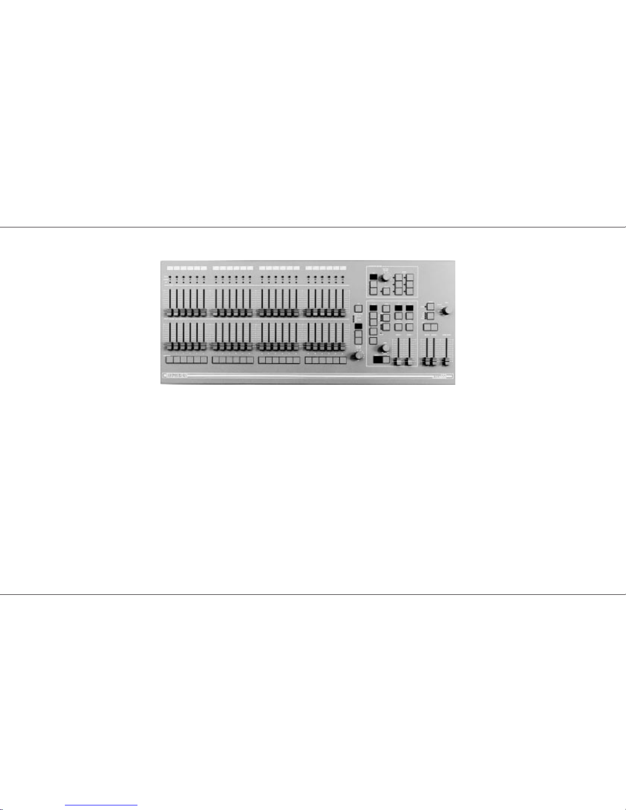
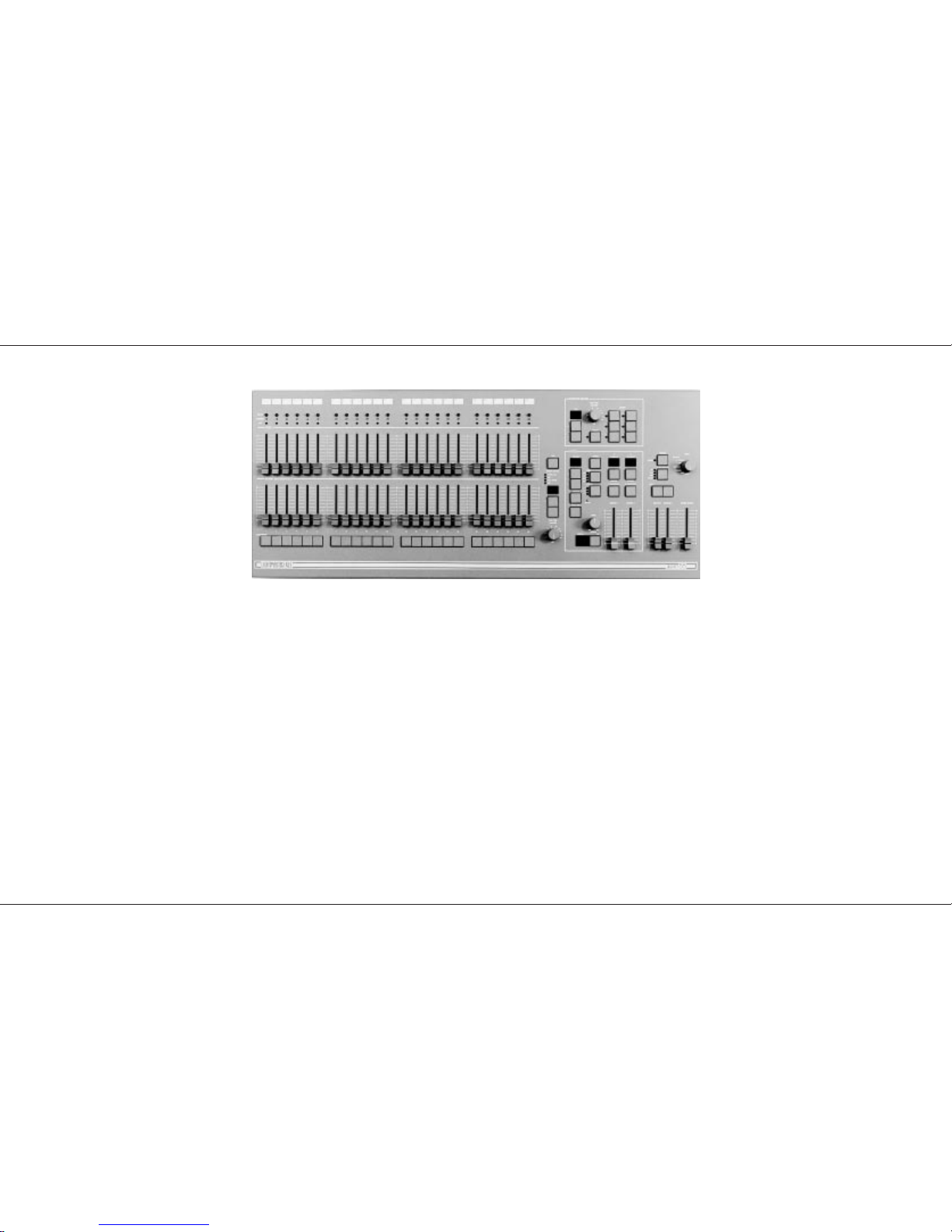
The Desk
The Lightmaster XLS is two separate 24 channel
lighting desks in one box. This provides 24
channels of fully featured traditional lighting
control and 24 channels of auxiliary control, for
equipment such as colour changers.
The main 24 channels are associated with 24 sub
masters, 216 memories, fade times, 9 effects, 2
effects sub masters, with analogue and DMX
outputs.
p4/4
The 24 auxiliary channels are programmed into 9
pages of 6 memories ( only one can be accessed
at a time), fade times and DMX outputs.
The desk has seven distinct sections: Master
controls, Presets, a Memory section, an Effects
section, the Auxiliary / Colour Control, the Midi
function and the Super User function including
Memory Card. These sections can be used to
control the output channels in a variety of ways.
➤
The Master controlsprovideoverall control of the
entire desk.
➤ The Presets offer manual control of individual
channels.
➤ The Memory section allows storage and retrieval of
lighting scenes, using the B preset as memory
masters.
➤ The Effects section allows storage and retrieval of
chase and audio effects.
➤ The Auxiliary / Colour Control section allows
storage and retrieval of 54 memories.
➤ The Midi function allows the desk to operate with
midi equipment.
➤ The Super User functions allow protected access to
functions that affect the overall desk operation
including Memory Card saving and loading.
DMX 512
Each Lightmaster XLS has a USITT DMX 512
output as standard. Under Super User control, it
will output DMX signals to the 1990 or pre 1990
standards. There are two built in soft patches
both allowing up to 96 / 512 dimmer channels to
be addressed. loop timing at 512 is 128 channels
per 40 ms
MIDI
The Lightmaster XLS uses MIDI in four ways:
➤
As a means of linking two or more Lightmaster XLS
desks for memory transfer or for Master/Slave
operation
➤ To allow a relatively simple electronic keyboard to
control individual channels and memories
➤ To allow more complex instruments such as
sequencers to control scene changes, even to the
extent of making such changes into a sophisticated
chase
➤ To allow connection of a foot switch to remotely
operate the Effects Go button.
The Memory Card
A Zero 88 Memory Card will store all the
memories and set-up of a Lightmaster XLS.
Page 4 7359700/p4/4
Page 6

Master Controls
These controls set the general operating
conditions for the entire desk. The Master
functions determine the mode of operation, the
functions of the buttons throughout the desk, and
the maximum output level for any channel.
p5/4
Master Controls
ON/OFF SWITCH:
Supplies power to the desk (Back panel).
MODE SWITCH:
A rotary switch which selects Preset, Run,
Program, Patch DMX, MIDI Set-up Out, or MIDI
Set-up In / Slave modes of operation.
GRAND MASTER:
Sets maximum level for all outputs.
FLASH FUNCTION:
Determines the function of flash buttons (see
notes).
MASTER A / B
Sets maximum level for Preset A, Preset B /
Memory Masters.
NOTES
*
Flash Functions:
Off: Flash Buttons do not function
Flash: Pressing a Flash Button will cause the channel,
memory or effect to be mixed in to the current outputs.
Solo: Pressing a flash button will cause the channel, memory
or effect to be output with all other outputs suppressed.
Preview (Run and Program Only): Pressing a flash button will
display the contents of that memory on the preview leds
without affecting the output of the desk.
*
Mode Switch
When switching from Run Mode to Preset Mode there is a
small delay, before going into Preset Mode. So if you switch
into Presets Mode by accident you can go back into Run
Mode and not need to set up Pages and Patterns etc.
Switching from Presets to Run after the delay resets the
Effects and Memory Page to 1.
Master Controls
7359700/p5/4 Page 5
Page 7
Presets Mode Operation
In Presets Mode all effect and memory functions
are disabled, offering a completely manual
system.
A scene can be set up on Preset A or B using the
individual channel faders. The Master A / B
faders can then be used to manually crossfade
between scenes while still under the control of the
Grand Master.
The green channel lights always show the actual
output of each channel (i.e. the signal sent to the
dimmers, and hence to the lanterns).
Preset Controls
PRESET A & MEMORY MASTERS/PRESET B:
There are two sets of faders controlling individual
channels known as Presets (or Scenes); these
are referred to as Preset A and Memory
Masters/Preset B.
MASTER A/B:
Sets the maximum level of Preset A/B.
MASTER A/B FLASH:
Flashes Preset A/B to the level of the Grand
Master. If the outputs are fading between presets
then the fade will be overridden by the flash
temporarily.
FLASH / PREVIEW:
Whilst pressed, individual channels or memories
are flashed. If Flash Function is set to flash.
OUTPUT LIGHTS:
Brightness indicates current channel output.
FADE TIME :
Sets the time for a scene to fade in or out when
changed by Master A or B .
NOTES
*
Master Fader Levels
For each channel the level of the output is determined by the
channel fader, and the Master A (or B) fader, and the Grand
Master. i.e. with all three, set to 50%, the total effect is 0.5 x
0.5 x 0.5, so that the channel will be output at 12.5%
*
Dipless Crossfade
All crossfades between Master A and Master B are dipless.
*
Master A/B Faders
With Master A/B faders up, the levels on the Presets A/B will
be output from the desk directly. This applies whatever the
position of the Mode Switch.
B Master may be inverted in Super User. ( see page 20)
*
References to Preset B / Memory Masters
Faders are referred to in this manual as Preset B faders when
being used in Preset Mode and Memory Masters at all other
times.
*
MIDI
The desk will respond to MIDI input signals in Preset mode.
Ensure that any MIDI cable is unplugged until the operation of
MIDI on this desk is fully understood (See page 24.)
p6/1
Presets Mode Operation
Page 6 7359700/p6/1
Page 8

Turning on the Desk
1 Switch on the desk using the mains switch on
the back panel
2 Set the Grand Master full on (UP).
3 Set Master A and Master B faders to zero
(DOWN).
Setting Up Presets
1 Set ALL faders at zero, Fade Time to OFF,
set Grand Master to full.
2 Turn the Mode switch to select Preset
3 Set up one scene by setting the required
levels for each channel on the Preset A
faders, and a different scene on Preset B.
Dipless Fading Between Scenes
1 Slowly fade up Master A. The green Output
lights correspond to the desk output.
2 To manually fade in the next scene,
simultaneously push Master B up to full,
Master A down to off. You have direct control
over the speed of the scene change.
Timed Dipless Fading Between Scenes
1 Set Fade Time to 5 seconds.
2 Quickly fade up Master A; note that the scene
only reaches maximum output level after 5
seconds.
3 To crossfade to the next scene,
simultaneously push Master B up to full,
Master A down to off. The speed of the scene
change is set by the Fade Time. ( The
Master B fader may be inverted, see notes. )
4 Experiment with different Fade Times.
Flashing a Channel
1 Press Flash Function to select Flash.
2 Press one or more individual channel Flash
buttons. The channels selected have been
added into the scene at the level set by the
Grand Master.
Soloing to a Channel
1 Change the Flash Function to Solo.
2 Press one or more individual channel Flash
buttons. This time the channels selected have
come on to the level set by the Grand Master,
with all other outputs killed.
3 Release the Flash button to return the desk to
its previous state.
Flash/Solo for whole Presets
1 Press Flash Function to select Flash.
2 Set Master A down to off and push Master B
up to full.
3 Press the Master A Flash button to see the
effect of flashing a complete preset/scene.
4 Change the Flash Function to Solo.
5 Press and HOLD the Master A Flash button.
This time the complete preset/scene has
come on to the level set by the Grand Master,
with all other outputs suppressed.
6 Release the Flash button to return the desk to
its previous state.
Solo also operates on Memory Masters and the
Effects Memories.
HINTS
*
Grand Master Fader
This is usually set to full on during normal desk operation.
*
Solo
The action of solo can be particularly useful for creating a
sudden dramatic change, such as lightning flash or explosion
effect.
*
Auxiliary outputs
The actions of the Grand Master and Solo do not effect the
Auxiliary outputs.
*
Preset A Level
Press the Level button and select a channel by using the
channel Flash / Preview button. The memory Page Display
shows the Preset A level ( independent of the Master Levels).
*
Invert Master B
If using both presets you can invert the Master B preset in
Super User. See page 20.
p7/4
Presets Mode Operation
7359700/p7/4 Page 7
Page 9
Programming the Memory
The memories in the Lightmaster XLS are
arranged in 9 pages, each of 24 memories. The
B Preset Faders become 24 Memory Masters In
Run and Program Mode. This provides an easy
way of recording up to 216 scenes which would
otherwise have to be set up manually on the
Presets. Any scene may be previewed (indicated
on the Preview lights), before it is output.
Programming
In Program Mode, the Program light is on, the
scene to be recorded is set up on the desk
outputs. The faders of Preset A are usually used,
but the action of programming records all outputs
at that time. Whether from Memory Master,
Presets or Effects Master, but not Auxiliary
Memories. Any number of channels at any level
may be assigned to each memory. To program,
select the Memory Page using the +/- buttons,
then press the appropriate Memory.
Flash/Preview button to select the memory you
wish to program. Observe the appropriate
program light flashing also. The continuosly lit
channel preview lights show what is in the
memory now. Press the Program button to record
the new scene. Channel information in a memory,
is shown on the Preview lights each time the
memory is selected.
Programming Controls
PAGE + / - :
Selects Memory Page to be programmed.
PROGRAM:
Records levels currently output to memory.
PRESET A:
Sets individual channel levels for programming
FLASH / PREVIEW BUTTONS:
Select one of the 24 memories on each Page to
be programmed.
MEMORY CONTROL:
The four lights above show whether the numeric
display is showing the Memory Page, the DMX
Channel, MIDI information or Preset A fader
level.
p8/4
NOTES
*
Ch’ in Page display
This indicates “Channels”. ‘Ch’ is a preprogrammed memory
with Channel 1 permanently assigned to Memory Master 1,
Channel 2 to Memory Master 2 and so on. These memories
can be used to replicate two preset operation or to easily
provide the facility of fading, flashing or soloing a single
channel. If page ‘Ch’ is previewed, the display changes to
‘PC’. Programmable Memory Pages are numbered 1 to 9.
There is more about ‘Ch’ on page 9.
*
Error Messages
These are listed on page 33.
*
Memory Master Faders
Used for outputting a previously memorised scene.
*
Recording of Output
When the Program button is pressed, the state of the outputs
is recorded. If one or more Memory Masters are outputting a
memory with outputs from Preset A, the complete resultant
scene is recorded.
*
Preview lights
come on for each channel recorded over 5%.
*
Preset A level Match
The display is not effected by Master A or Grand Master
control. Available in Presets, Run and Program Mode only.
see page 11.
Programming the Memory
Page 8 7359700/p8/4
Page 10

Setting up the Desk for Programming
1 Set ALL faders at zero, set Grand Master to
full.
2 Turn the Mode switch to Program. Program
light will come on.
3 Push the Master A fader to full.
4 Check memory Page is showing ‘1’.
Programming a Memory
1 Select the memory Page required using the
page ‘+’ and ‘-’ controls.
2 Press the Flash/Preview button to select the
memory (1-24) that you wish to program. The
Preview lights will show any previously
programmed scene; the Preview light of the
memory selected will flash slowly and the
Page display will change from 1 (for example)
to P1, a reminder that the page selected is
being previewed.
3 Set up a scene on the Outputs using Preset
A, other Memory Masters or a static Step
from an Effect Pattern.
4 Briefly press the Program button to record
the output levels in to memory. The new
memory is immediately displayed on the
yellow Preview leds, to verify that this
information has been recorded.
5 Repeat steps 1 to 4 to program additional
memories.
Clearing a Memory
1 Select a memory to be programmed or
program a new memory as described above.
2 Set the Grand Master down to zero.
3 Briefly press Program to clear the memory by
storing a scene with all levels at 0. Any
preview lights that were on go off.
Blind Programming
This is possible using the Level Match feature
described on page 11.
Editing (Using Level Match in Program)
1 Set up and record a scene in memory. Leave
the desk in Program.
2 Move all faders to 0, leave Grand Master at
10.
3 Press the memory Flash/Preview button of
the memory you want to edit and hold it
down until the Preview lights flash to preview
the scene that was recorded.
The channel Preview lights will flash quickly
on any channels where the channel level on
Preset A needs to be decreased to match the
programmed level. The channel Preview
lights will flash slowly on any channel where
the channel level on Preset A needs to be
increased to match the programmed level.
To see the level on the output leds / dimmers
move the Master A to full.
4 To edit any channels, adjust the appropriate
Preset A channel fader until the associated
channel Preview light is on continuously.
Be careful! When the Preset A fader level
is at the recorded level, the fader ‘catches’
the level and then has LIVE control.
5 Now move the fader to the required level.
The preview light is still on continuously, this
shows the fader and memory are at the same
level. The memory has now been edited simply cancel Level Match by pressing the
Flash/Preview button once.
HINTS
*
Programming Appears Not To Work
Check that the Grand Master and Master A are up to full,
since with Master A at zero, a blank memory will be
programmed. Simply fade up the Grand Master or Master A
and reprogram the memory.
*
The scene recorded is not the scene that was
wanted.
Check that none of the Memory Masters or the Effects Master
were up whilst you were programming. If any of these
masters were on, this will be shown on the Output Lights and
the memory that will be recorded will be the mixture of levels
set by Preset A and levels set by the Memory Masters that
were up. This is an essential feature of the desk.
*
Reprogramming a Memory
If the memory chosen is not empty (shown by the preview
lights coming on), pressing the Program button will overwrite
any previous information with the current settings of Preset A;
the old memory will be lost.
*
Changing the Memory Selected
To change the memory that you have selected within a Page,
simply press another memory Flash/Preview button. To
remove the memory preview information from the Preview
lights in Run, press the Flash/Preview button of the memory
once again.
*
‘PC’ in the Page Display
When ‘PC’ is shown (Preview Ch), this means that ‘Ch’ was
showing in the Page display when the memory was selected.
Pressing the Flash button again will return the display to ‘1’ or
using the Page +/- buttons will move to the correct Page
required.
*
Flash Function
In Program Mode the Flash Function is disabled.
*
Page CH:
Is a preprogrammed memory page where Memory Master 1
is programmed with Channel 1 and Memory Master 2s is
programmed with Channel 2 etc.
p9/4
Programming the Memory
7359700/p9/4 Page 9
Page 11

Manual Memory Operation
Using Memories
In both Run and Program, memories are
assigned to the twenty four Memory Master
faders giving direct manual control over the
memory output levels.
In Run, the Memory Flash/Preview button will
Flash or Solo complete memories. Memories may
be automatically faded in and out at speeds
determined by the Fade Time control. Fades are
dipless. Times can vary from instantaneous (Off),
up to a maximum of three minutes.
In Program, the Flash/Solo functions are
disabled; the preset B Flash/Preview buttons are
used for selecting individual memories.
Level Match
When in Run or Program Mode, the levels of a
scene in memory may be recreated on Preset A.
This makes editing of scenes previously recorded
very easy. This also works for Effects and
Auxiliary Memories.
p10/4
Page Overlay
When a memory is being used by either pressing
a Flash/Preview button or by fading a Memory
Master up, the output will not alter if the Memory
Page is changed. This feature is called Page
Overlay.
The operation of this feature is shown by the slow
flashing of the appropriate Preview light. This
indicates that the scene being output is not the
scene associated with the current page.
When Memory Masters are in Page Overlay or
Level Match and a Memory Master, Effect or Aux
Memory is previewed, then the preview lights
show the preview data, not the Page Overlay or
Level Match data. The outputs do not change.
Turning the preview off restores the data.
In Run Mode changing pages while previewing a
Memory Master turns off the preview.
Manual Master Controls
PAGE + / - :
Selects Next Memory.
Pressing both together selects ‘1’
MANUAL MASTER/PRESET B:
These faders set the maximum channel level for
each memory
FLASH:
Run only. Flashes/Solos the appropriate memory
(dependent on Flash Function)
PREVIEW :
Memory contents are displayed on the Preview
lights
Notes
*
Errors
Error messages are listed on page 33.
*
Level Match
The position of Master A does not matter when recreating a
scene in Level Match, but make sure it is at the required level
when re-recording!
*
Page Overlay / Masters
Masters have no effect on Page Overlay facility.
Manual Memory Operation
Page 10 7359700/p10/4
Page 12

Outputting a Memory
1 Select the required Page.
2 Ensure that Master B is at the required leve.l
3 Either fade up the Memory Master fader, or
press a Flash/Preview button (Run mode
only).
Previewing a Memory
1 Ensure that the Flash Function is set to
Preview, then select the Page required.
2 Press the required memory Flash button
once. The Preview leds will show all channels
that are ‘On’ by more than 5%. One Preview
led will flash slowly to indicate which memory
is being previewed.
Using Level Match in Run
1 Set up and record a scene in memory.
2 Switch desk to Run and move all faders to 0;
leave Grand Master at 10.
3 Press Flash Function to select Preview.
4 Press the Memory Flash / Preview button
once, the preview lights will come on to
indicate those channels recorded. One
Preview light will flash slowly to indicate which
memory is being previewed.
Press and hold the same Flash/ Preview
button. All the preview lights will come on,
some will flash and others on continuously.
If the preview light for a channel is on and is
not flashing, the Preset A fader is at the
level recorded into memory.
If the preview light is flashing slowly the
Preset A fader is below the level set in
memory.
If the preview light is flashing quickly the
Preset A fader is above the level set in
memory.
p11/4
5 Adjust the Preset A faders so that all
channels preview lights are on continuously.
The scene in memory is now recreated on
Preset A.
To cancel Level Match press the
Flash/Preview button once.
Using Page Overlay
1 Set memory Page to 1 and program Memory
Master 1 with a scene.
2 Set memory Page to 2 and program Memory
Masters 1 and 2 with different scenes.
3 Set the Mode to Run and Memory Page to 1;
ensure Master B is at the required level.
4 Fade Memory Master 1 to full.
5 Set Memory Page to 2.
Note that Preview light 1 comes on and
flashes slowly and the outputs do not change.
6 Fade Memory Master 2 to full.
The outputs of Memory 1 Page 1 and
Memory 2 Page 2 are mixed on a highest
wins basis.
7 Fade Memory Master 1 to 0 and then up to
full again.
The Preview Light goes off and Memory 1
Page 2 and Memory 2 Page 2 are now mixed.
Hints
*
Overwriting a Memory
Recording a new memory on to a Memory Master will
overwrite the old memory.
*
Page Overlay with Fade Times
If the Fade Time is on, page change will not happen until the
output is at zero. To illustrate this, try the Page Overlay
example with a Fade Time of 5 seconds. At step 6, fade
Memory Master 1 to 0 and wait for the outputs to reach 0
before fading the Master to full again. Note that the Preview
light stops flashing when the page has changed.
*
Blind Programming
Using the Level Match feature in Program with the Preset A
Master at 0 allows creation and editing of scenes ‘Blind’.
When editing scenes, obtain a Level Match of the channel(s)
concerned, then simply edit as required. Scenes may be
similarly created from scratch.
*
Preset A Level.
Press the memory control button until the Preset A level light
coes on. The Memory Page Display now shows a read out of
the position of any selected A Preset fader . Selection is by
the Flash /preview buttons. The Memory Master can be at
zero.
Manual Memory Operation
7359700/p11/4 Page 11
Page 13

Effects SectionProgramming
The effects section can hold nine sequential
memories, each having up to 99 steps (subject to
a combined total of 250 steps), and one audio
effect. Each sequential effect may be run
manually (with or without a Fade Time) using the
Go button and/or automatically by the four drives
available. The drives are: Bass, Varispeed, Auto
chase and Beat. In Run mode the Speed and
Attack of the sequence may be varied as required.
The audio effect consists of four programmable
scenes, the intensity of each scene being
modulated by a sound frequency band filtered
from the Audio input.
Effects Programming
An effect is a set of up to 99 level memories, each
of which is called a step. Thus any number of
channels, at any level, may be recorded as one
step. Steps are usually programmed using
Preset A .
The effects section has 3 parts, Programming
module and two playback modules. In Program
Mode, playback 2 does not function and playback
1 is locked “Live” to the Program module.
Audio Effect Programming
The audio effect is a set of four audio memories.
There are two types of audio effect available:
Sound to Light or Ripple sound.
For Sound to Light, the overall output level of
each audio memory in the set is modulated
according to the sound level in four harmonic
bands (Bass, Low Mid, High Mid, Treble).
For Ripple sound, as the sound level increases,
the level of audio memory A1 is increased to
100% first, followed by A2 being increased to
100% until at maximum sound level A4 is at
100%. This effect is very complex and
spectacular. It is worth trying with channels 1 to 6
at 100% on A1, 7 to 12 on A2 and so on. Any
number of channels at any level may be recorded
into any audio memory. The audio memories are
usually programmed using the A Preset or may
be copied from the Memory Masters.
P12/4
Programming controls
SEQUENCE + / - :
Selects patterns. Blank , Audio, One .....Nine.
Pressing + and - together selects pattern one.
PRESET A:
Sets individual channel levels for programming.
PROGRAM:
Records all Output levels at once as an effects memory.
ADD STEP:
Advances step number or audio memory number for
programming.
DELETE STEP:
Deletes displayed step number from sequence.
SO:
Steps through a stopped effect sequence; in Program,
cycles through the audio memory to be programmed.
PREVIEW:
Enables previewing and programming of the effects.
FLASH / PREVIEW
In Program Mode they have no effect.
In Run Mode shows on the preview lights those steps
running in the associated Effects Master and which
Drive, Attack modifiers are being used.
Effects Section Programming
Page 12 7359700/P12/4
Page 14

Sequential Effects Programming
Programming a Sequential Effect
1 Turn the Mode switch to Program, the
Program light will turn on, all faders down to
0, Grand Master to full.
2 Press Effects Preview to enable chaser
programming. Pattern No. display and the
Program light will flash slowly, to indicate it is
being previewed. Playback 1 Display shows
L for Live. (See NOTES).
3 Select the Pattern to be programmed using
the Effect +/- buttons. Press and hold the
Delete Step button to clear any existing steps.
The Step No display will show ‘—’ . If the
button is pressed an extra time, the display
will show ‘Er’ for a brief period, then ‘—’.
4 Set Preset Master A to full and set up the first
scene of the sequence on Preset A.
5 Press Program to record the step.
The channel preview lights will come on to
show those channels recorded into the step.
6 Press Add Step to add the next step, then
Repeat steps 4, 5 and 6 until the sequence is
complete.
Do NOT press Add Step after the last step.
7 Leave Program Mode or go back to step 3 to
Program another Pattern.
Editing a Step in a Sequential Effect
1 Turn the Mode switch to Program.
The Step No is reset to 1.
Use the Effects +/- to select the effect to be
edited.
2 Press the Go button to find the step that you
wish to edit.
3 Select Level Match by pressing and holding
the Effects Preview button (see pages 8/9 for
details on Level Match). Effect Playback 1
becomes Live (See NOTE).
P13/4
4 Fade the required individual Preset A fader(s)
up until the associated preview light on each
channel has stopped flashing, then, under live
control, set the new level(s).
5 Press the Effects Preview button once to exit
Level Match.
Adding a Step to an existing Sequence
1 Set the Mode switch to Program. Ensure that
all faders except for Grand Master are at 0.
2 Press the Effects Preview button once to
select the effect.
3 Select the Pattern number required and press
the Go button to select the Step No that is
before the step to be inserted.
4 Set up the scene on the outputs to be
recorded.
5 Press Add Step to add a blank step after the
step that was being displayed.
6 Press Program.
7 Turn the Mode switch to Run, the effect will
be Live in the Playback 1 Display. Fade the
Effects Master 1 to 10 and Master A to 0 to
view the resulting sequence.
8 Leave Program Mode or select an other
Pattern for editing.
Deleting a Step in a Sequence or deleting an
entire Sequence
1 Turn Mode switch to Program.
2 Fade the Effects Master to 0. Press the
Effects Preview once to select the memory.
3 Select the sequence to be edited using the
Sequence +/- buttons and the Step Number
using the Go button.
4 Press Delete Step once to remove the step
number that is displayed.
Press and hold to delete the entire sequence.
Note
*
Live
When Transfer is pressed and held the Playback Display
shows “L” for live.
Any further changes to the modifiers are directly transferred to
the outputs.
Sequential Effects Programming
7359700/P13/4 Page 13
Page 15

Audio Effects Programming
Programming the Audio Effect
1 Set the Mode switch to Program and ensure
that all faders are at 0 except for Grand
Master which should be at full.
2 Select the sequence called ‘A’ using the
Sequence +/- buttons. The Step number
display will show ‘A1’. See note.
3 Press the Effects Preview to select the Effects
memory. Playback 1 becomes Live.
4 Set up the scene required for the first audio
memory on the outputs. Press Program to
record the scene and note that the Preview
lights come on as the memory is
programmed.
5 Press Add Step (or Go) to select Audio
memory 2. Set the scene required on the
outputs and press Program again.
6 Repeat for Audio memories A3 and A4.
7 Leave Program Mode.
P14/4
Editing a Step in an Audio Effect
1 Set the Mode switch to Program, select ‘A’ in
the Pattern Display, fade Master A to Full.
2 Press the Effects Preview button to observe
the output of the A1 audio memory on the
preview display.
3 Press the Add Step or Go button to select the
audio memory you wish to edit.
4 Select Level Match by pressing and holding
the Effects Preview button.
5 Fade the required individual Preset A fader(s)
up until the associated preview light on each
channel has stopped flashing, then, under live
control, set the new level(s).
6 Press the Effects Preview button once to exit
Level Match.
7 To repeat for other audio memories, repeat
steps 3 to 6.
Clearing an Audio Memory
1 Turn Mode switch to Program all faders to 0.
2 Press the Effects Preview once to select the
memory.
3 Select the audio memory using the Sequence
+/- button and the Step Number using the Go
button.
4 Press Program once to program zero levels
into the audio memory selected.
5 Repeat steps 3 and 4 for any other audio
memories that need clearing.
Audio Effects Programming
Page 14 7359700/P14/4
Page 16

Effects Operation
Effect Operating Controls
SEQUENCE + / - :
Selects one of the sequences or Audio Effects. In
Run, both pressed selects the first programmed
sequence.
EFFECT DRIVE:
For Sequential Effect, selects auto, varispeed,
bass or Beat drive.
For an Audio Effect, selects ‘Sound to Light’ or
‘Ripple sound’ type Drive.
ATTACK :
Determines type of crossfade between steps of a
chase or the type of Audio Effect.
SPEED:
Sets the speed of the chase sequence or the rate
of attack of an Audio Effect.
EFFECTS MASTER 1 and 2:
Sets maximum output level for Effects.
PREVIEW :
Displays effect on preview leds.
GO:
Outputs next step of stopped chase sequence.
FLASH/Preview:
Flashes/Solos and previews the effect running on
Effect Master 1 or 2.
NOTES
*
Auto / Varispeed / Bass Chase/Beat
Auto chase requires no sound input, with chase speed
determined directly by the speed control.
Varispeed speeds up and slows the chase according to the
tempo of the music on the audio input, with the speed control
used to set a basic speed.
Bass chase will step through the pattern on a bass beat giving
a Sound to Light effect.
Beat Allows you to input the rhythm the effect will follow.
*
Attack
Three types of crossfade are available:
Switch on / switch off
Switch on / fade off
Fade on / fade off
Switch on / fade off is particularly useful for PAR cans.
*
Pattern Display shows only sequences that have
been programmed.
When turning the Mode switch from Program or Presets to
Run, only Effects that have been programmed will be shown
on the Pattern display.
If say 2, 5 and 7 are programmed, ‘2 ‘will be displayed and
only 2,5,7 or A may be selected.
Pressing + and - together takes you to Pattern 1, in Run
Mode to the first pattern that has been programmed.
*
Audio filters.
A1: Bass
A2: Lower middle
A3: Upper middle
A4: Treble
P15/4
Previewing Sequential Effects
1 Turn the Mode switch to Presets, Speed to
off, all faders down, Grand Master to full.
2 Wait until the Flash Function light comes back
on. ( See NOTES page 5).
3 Set Mode to Run.
4 Select an Effect Pattern using + and -, only
those programmed will be available.
5 Set Flash Function to Preview. Press Effects
Preview.
6 Preview lights will show step one of the effect.
7 Pressing the Go button will step through the
effect.
8 Adjust the Speed control from off to Autorun
the effect. (unless in Bass drive see NOTES).
9 Adjust the Drive and Attack to suit.(see notes)
The Effect is now running on Previews only.
Running Sequential Effects (with Fade Time)
1 To send an effect to the outputs set it up as
above then press Playback 1 or 2 Transfer
button.
2 The Playback Display displays the same
number as the Pattern Display.
3 Set the Fade Time to 5 Seconds.( or to off for
no fade time)
4 Move the appropriate Effects Master to full
quickly, to see the effect fade up and run on
the outputs.
The Preview lights will follow the Green
output lights.
The Output is running in the Playback, with a copied set of
modifiers( Pattern, Drive, etc) and the Previews are running in
the Pattern Display.
5 Change the Speed. The Playback continues
at the set speed, The Previews change with
the Speed control.
6 Now change the Pattern number and all the
Modifiers and Transfer a different effect to the
Effects Operation
7359700/P15/4 Page 15
Page 17

other Playback. Both effects are now running
independently.
Note.
By pressing and holding a Playback Transfer the playback
Display displays “L” , this means live. Any changes to the
modifiers, Pattern Number etc are directly transferred to the
playback and thus the outputs. Pressing the Transfer again
removes the “L”.
Previewing and Outputting an Audio Effect
1 Turn the Mode switch to Run. and press Flash
Function to select Preview.
2 Ensure a suitable audio feed is connected and
on.
3 Select the Audio Effect using the Sequence
+/- buttons and the drive by pressing the Drive
button.
4 Press the Preview button once to observe the
outputs on the Preview lights.
5 Fade the Effects Master up to output the
effect.
Adjusting the Speed control will vary the slope of
attack on the Audio Effect.
Using a Memory to program a step in a
Sequence
1 Turn the Mode switch to Run, set all faders to
0, set the Grand Master to full.
2 Press the Flash Function to select Preview.
3 Using the Memory Page +/- buttons, select
the Page required and press the Preview
button of the memory on that page to preview
it if required. Set Master B to the level
required and the Memory Master to the level
required.
4 Press the Effects Flash/Preview button.
5 Press the Effects Sequence +/- buttons to
select the sequence required and the Go
button to select the step to be programmed.
P16/4
6 Turn the Mode switch to Program, press
Effects Flash/Preview once to select the
Effects section and observe the Program light
flashing.
7 Press Program to transfer the memory that
was set up on the Output lights into the step
selected within the effects sequence.
8 Repeat for transferring further scenes.
Running a Pattern with Beat drive.
The drive option Beat, allows the operator to
directly input the speed that a pattern is running
at with out using the speed pot. Patterns 1 to 9
only.
1 Set the Mode switch to Run.
2 Select the required pattern, using the + / -
buttons.
3 Press the Drive button until the Beat light
comes on.
4 The Rhythn light will also come on.
5 Select Flash Function preview. Press Effects
Preview.
6 Press the Go button, wait 1 second, press the
Go button again. The Pattern will now run
with 1 second steps on the preview lights.
Press the Go button again twice with a 2
second gap. The pattern is now running with
a 2 second gap.
7 Press Transfer and fade up the Effects Master
to see the chase on the outputs.
If used live this option is an easy way to make a
chase synconise with a music track, e.g. a regular
drum beat.
NOTES
*
The letters ‘ER’ or ‘NF’ are displayed
When Delete Step is pressed and the step number is ‘—’, the
letters ‘ER’ (error) are displayed; if ‘NF’ is shown (No Frames),
there are no sequence steps available as the memory is full.
*
Effects Speed, Drive and Attack
While an effect is running and the Playback Display shows L
the Pattern Display, Speed, Drive and Attack may be
modified ‘live’ as required. Only One Effect Playback can be
Live at a time.
Once either Transfer Button is pressed, ‘live’ control is lost.
These controls are then used to set up the next effect.
*
Copying Memories to Sequence Steps
They may be copied from a memory or combination of
memories by setting the memory Master(s) to the required
level(s) and recording the resultant scene onto the step.
HINTS
*
Using a sequential effect as a set of 99 theatre
style memories.
Run mode. The Pattern may be simply used as a set of
theatre memories by setting the Speed knob to manual (OFF)
and the Fade Time knob to the required crossfade time
between memories. Pressand hold the Transfer button for
either of the Effects Masters. Set the Attack to the lower
setting,
. Pressing the Go button will now crossfade between steps
within a sequence memory at the fade time set by the Fade Time
control. Complex memories may be easily set up using the standard
Memory Masters and then simply transferredto the Effect memories.
*
Midi foot switch.
The Go button may be remoted via midi. It will only accept a
step rate of 1 per second. Seepage 22.
*
Transferring sequence steps to a Memory Master
Scenes may be transferred from an effects step to a Memory
Master by setting the Effects Speed switch to manual,
selecting the appropriate step, setting the Effects Master to full
and Masters A and B to 0. The scene is displayed on the
Output lights and may be recorded onto a Memory Master in
the normal way.
Effects Operation
Page 16 7359700/P16/4
Page 18

Auxiliary / Colour Control
Auxiliary / Colour Control
The 24 channel Auxiliary control section has nine
pages with six memories per page and is
independent from the rest of the desk, apart from
in programme mode.
The Memories may be Previewed and (if
required) a cross fade time set for fading
between memories. Crossfades are dipless.
The output from the Aux Memory is via the DMX
512 signal. The 24 channels can be soft patched
in DMX. (see page 21). In Presets or Run Mode
the output is not effected by other operations in
the rest of the desk and in Program Mode is only
effected while programming the Auxiliary Control
section. This allows you to edit a dimmer
channel / memory while still outputting a colour
memory.
The outputs from this section of the desk work on
a latest takes precedence basis.
P17/4
Auxiliary controls
PAGE +/-:
Selects page to be used.
MEMORY 1,2,3,4,5,6:
Selects Memory number.
FADE TIME:
Selects dipless cross Fade time between memories ( 0
to 180 seconds).
PREVIEW:
Selects the Auxiliary Colour Control section, for
Previewing or Programming.
PRESET A:
Is used in Program Mode to program Auxiliary
memories.
Notes
*
Auxiliary outputs
The output from the Auxiliary Control is independent from the
rest of the desk except when Previewed in Program Mode, in
DMX set-up Mode (soft patch) or in Midi Mode.
*
Auxiliary Memories
Only one Auxiliary Memory can be output at a time.
*
Flashing.
The Page Display and Memory Light flashing while in Preview
Mode, indicates the Memory being Previewed.
*
Crossfading.
While a crossfade is in progress the Light on the Memory
fading in will flash until the fade is complete.
*
Changing Pages.
If pages are changed the output does not change, until
another memory is selected. If the current memory is not on
the current Page, as shown in the Page Display, none of the
memory lights will be on.
*
Auxiliary Memory Preview.
Auxiliary Memories are Previewed on the red lights under the
Channel Preview lights.
Aux Memories can not be previewed in Presets Mode.
*
Page +/-
Pressing both together selects Page 1.
Programming Auxiliary Control Memories.
Auxiliary / Colour Control
7359700/P17/4 Page 17
Page 19

Programming the Auxiliary Control.
Programming the Memory is very Quick and is
done From the Preset A faders. The level of the
Grand Master and Master A fader have no effect.
Channel 1 Preset fader controls the first Aux
Channel no matter where it is soft patched to (see
page 21).
Programming for colour memories is best done
after having done at least the first plot of the
dimmer Memories, as the dimmer channels will
need to be on to see the colours.
Programming is best done by building up scenes.
Programming the Auxiliary Memories.
1 Set all faders down, Mode switch to Program.
The Program light comes on.
2 Using the +/- Page buttons select the required
page.
3 Using the Memory buttons Select the memory
required.
NOTE That Memory will now be on the DMX
signal.
4 Press Auxiliary control Preview button. (The
Program and Memory light and Page Display
now flash.) The 24 Preset A faders now have
LIVE control over the Auxiliary channels on
the DMX signal.
NOTE The Grand master and Master A have
no effect.
5 Adjust the Preset A faders to the required
output.
6 Press the Program button. The scene is now
recorded. The red Aux Preview lights will
come on for any channel recorded above 5%.
7 Select another Memory. The DMX output
does not change, as it is still LIVE from the
faders. The Auxiliary Preview lights show
what channels are used in the currently
selected memory.
8 Repeat section 5 to 8 as required to program
other memories.
p18/4
Programming Auxiliary Memories as Colour
Memories
This is the same as above except that to be able
to successfully program a colour changer you
need the attached luminaire on. The Lightmaster
XLS Makes this very simple.
1 All faders down, Grandmaster and Master B
up to full, Program Mode.
2 Select Memory page CH.
If any other page is selected ,previously
programmed scenes can be accessed rather
than Channel Memories.
3 Using Preset B turn on the channels /
memories of those colour changers you want
to program.
4 Select the Auxiliary Memory to be
programmed.
5 Preview the Auxiliary Control.
6 Set the colour changers to the required colour
by moving the Preset A faders.
7 Press the Program button to record the
Auxiliary Memory.
8 Repeat from step 3 to program other
Memories.
Edit Auxiliary Memories In Program Mode
1 All faders down, in to Program mode.
2 Set up Luminaire outputs as required. Select
Auxiliary Page / Memory.
3 Press Auxiliary Control Preview.
Control of the DMX signal is now live on the
A Preset faders.
4 Press and Hold the Preview or Memory
button. The DMX control is now from the
memory and the Auxiliary Preview leds are in
Level Match.( see page 7 for Level Match.)
5 Carefully move the A Preset faders until the
Flashing Preview lights stop flashing.
Caution: Once the Auxiliary Preview light has
stopped flashing the fader has LIVE control
over the DMX output and the contents of the
Memory ( you don’t have to push the Program
button to record the new scene).
6 Adjust the channels as required. DO NOT
press the Program button as this will record all
the fader positions not just those that have
moved.
7 When the channels have been edited select
another Auxiliary memory to edit another
memory , from step 4.
8 To exit either Preview a different section of
the desk or leave program Mode.
NOTE
*
Other Outputs.
Other outputs will still run while programming the Auxiliary
memories as described in the individual sections.
Programming Auxiliary Control Memories.
Page 18 7359700/p18/4
Page 20

Auxiliary Control Operation
Outputting an Auxiliary Memory.
Operates in Run or Presets Mode.
1 Select Auxiliary Page required.
2 Press Memory Button (light comes on next to
it).
3 The Memory Programmed goes straight out
on the DMX signal.
4 Select another Memory, the light for the
previous memory goes out and the new one
comes on), its outputs go directly on to the
DMX signal.
Auxiliary Memory from another Page.
1 With Page 1 Memory 1 Selected and
outputting.
2 Select Page 2 all Memory lights go off,to
show no memory from this Page is selected,
but DMX output does not change.
3 Select a memory from Page 2, its Light
comes on and the DMX output is changed.
Dipless crossfades between Memories.
1 Select Page 1 Memory 1.
2 Set the Auxiliary Control Fade time to the
desired speed ( 0 to 180 Seconds).
3 Select a new page if required.
4 Select the new Memory.
5 The old memory fades out and the new one
fades in at the selected speed. While fading
the light on the new Memory flashes slowly
until the fade is complete. Adjusting the Fade
time during fading will cause the fade time to
change.
p19/4
Recreating Auxiliary Memories with Level
Match.
1 All faders down, Go into Run Mode.
2 Select the Auxiliary Page and Memory that
needs to be edited.
3 Set the Dimmer Memory Masters as required.
4 Set the Flash Function to Preview.
5 Press the Auxiliary Control Preview, The red
Auxiliary Preview lights come on for those
channels recorded above 5%.
6 Press and hold down Aux Control Preview or
the Memory button. The Auxiliary Preview
lights will go into Level Match ( see page 7 for
a description of Level Match).
7 Ensure Master A is down, move each Preset
A fader until the associated Auxiliary preview
does not flash. The A Preset is now the
same as was recorded into the Memory.
8 Go into Program Mode. The A Preset faders
now have live control over the DMX signal.
9 Adjust any channel as required.
10 Press Program to record the new scene.
11 Go to step 1 to edit another Memory.
Previewing an Auxiliary Memory, while
outputting another Memory.
1 Program Page 1 Memory 1 and Page 2
Memory 2
2 Output Page 1 Memory 1 in Run Mode.
Select flash Function, Preview.
3 Press Auxiliary Control Preview, Page 1
Memory 1 will be previewed. The Memory
light flashes slowly to to show it is being
previewed.
4 Press the Page + button to select Page 2.
5 Memory 1 light now flashes slowly.
6 Press Memory 2 button, it’s light now flashes
slowly to show it is being Previewed. The
red Auxiliary Preview lights come on for any
channel recorded above 5%. The output is
still from Page 1, Memory 1.
7 pressing Preview or Flash Function turns the
Preview function off.
Auxiliary Control Operation
7359700/p19/4 Page 19
Page 21
Super User Operation
Introduction
The Lightmaster XLS desk has a range of options
which are accessed in Super User mode.
Whilst in Super User, Presets A and B work
normally; Memory, Sequence and Midi functions
are disabled.
The principal options are:
Memory Card Storage
Set individual channels for Strobe operation
Set individual channels for Full Level
operation
Setting 1990 DMX / original DMX
Setting DMX for 96 or 512 channels
Inverting Master B fader
Clearing all the memories
Resetting DMX, Midi and channel settings
To access Super User:
1 Turn Mode switch to Preset.
2 Press and hold down the Memory Page + and
- buttons together, then turn the Mode switch
to Run; release both buttons.
The Memory Page display shows SU; the
Step No display shows the software version
number.
To exit Super User:
Turn Mode switch back to Preset.
Memory Card Storage
The Zero 88 Memory Card may be inserted at
any time in the slot at the back of the desk in the
middle.
The Card will store all the memories of a
Lightmaster XLS. It should NOT be left in the
desk when the desk is switched off as there is a
risk that the battery in the card will run down
more quickly.
The same card is used for the Sirius 24, Sirius 48
and Lightmaster XL but the information stored is
NOT interchangeable.
.
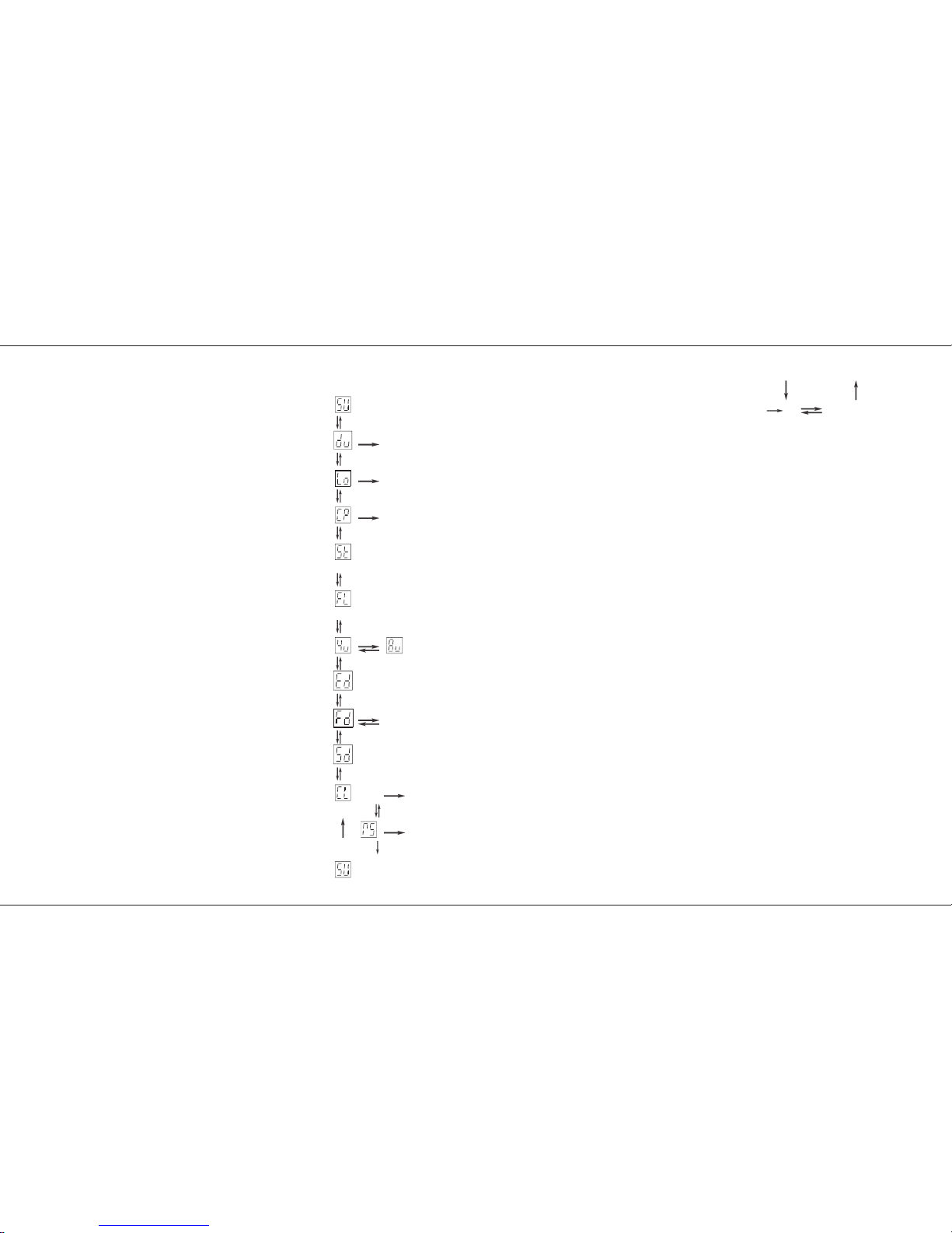
Super User Operation Diagram
Super User
Step No Display shows Program Version e.g. 0.6.
Dump
Dumps all Desk contents TO the Memory Card.
Load
Loads all Desk contents FROM the Memory Card.
Compare
Compares all Desk contents with those on a Memory Card.
Strobe
Select Strobe outputs by pressing channel flash buttons preview
lights indicate selection.
Full
Sets channel for Full Level (Switch) outputs by pressing channel
flash buttons preview lights indicate selection.
4 / 8 microseconds
1986 DMX break time (4 microseconds) 1990 DMX break time (8 microseconds)
Extended
Extends DMX from 96 to 512 channels. See note.
Fast DMX
Set to fast DMX as default See note
Split Dipless
Inverts Preset B Master fader in all modes. See note.
Clear
Clears Memory except Midi, DMX Patch and Flash/Strobe channel settings.
Reset
Resets Midi, DMX Patch and Flash / Strobe channel settings to their factory defaults.
Notes
Press Page + for or Page - for
Press Go for or
p20/4
Super User Operation
Page 20 7359700/p20/4
Page 22

Programming DMX Patch
*
Memory Card Operations:
A second or so after the Go button is pressed, the Page
display flashes slowly and the letters ‘GO’ in the Step No
display go out until the operation is complete.
If no Memory Card is present, the Step No display flashes ‘IC’
(Insert Card) until a card is inserted or the Go button is
pressed again.
Using Compare (CP)
If the Card contents are not the same as the desk contents,
‘NO’ with two flashing dots will be displayed in the Step No
display. Press Go to continue.
*
Strobe and Full Level Outputs
Channels default to proportional output. To set an individual
channel for Strobe outputs, press the required channel Flash
button to turn on that channel’s Preview light. Any channels
already set up for strobe operation will have their Preview
lights on.
The same procedure is used for setting Full Level outputs
(Full Level outputs are On / Off only).
*
Extended DMX.(512 channels)
Step display shows the 100’s, the 10’s and 1’s are shown in
the memory display. 512 channels will be transmitted at turn
on, mode changes, patch changes and page changes. At
least 96 channels will always be transmitted. If more than 96
channels are patched the DMX sends up to last channels
patched. NB 128 ch transmitted per 40ms. 512 ch takes
160ms.
*
Fast DMX
The Default is set to . DMX is sent at its maximium
possible rate. With DMX set to gapsare inserted
between each DMX channel data byte. This slows down the
DMX transmission enabling some recievers to operate
correctly.
*
Clearing Memories
There is a second or so delay before CL and RS are started.
It is not possible to clear the channel memories and the MIDI,
DMX Patch, Full Level and Strobe settings at the same time.
Two operations, CL and RS must be performed. Each is
totally independent of the other.
*
Split Dipless
The Preset B master will only invert if the Grand Master is at
zero.
P21/4
Programming DMX Patch
The 24 Dimmer output channels and 24 Auxillary
output channels of the desk can be patched to up
to 96 or 512 DMX channels. See Super User
options Page 18. The desk contains two
seperate soft patches.
The default state is that desk dimmer channels 1
to 24 are patched to DMX channels 1 to 24, and
Auxillary channels are patched 25 to 48. The
Default for Patch two is dimmmer ch 1, Aux ch
1,dimmer ch 2, Aux ch 2, etc. These defaults are
reloaded by the Super User Reset operation.
DMX allways transmitts at least 96 channels. If
more than 96 channels are patched, Then DMX
is transmitted up to the last patched channel.
DMX is sent out at 128 channels per 40 mS.
To select a soft patch:
1 Set Mode Switch to Patch DMX.
2 The Memory Control, DMX Channel light
comes on.
3 Memory Control Display shows the current
patch. ‘P1’ or ‘P2’.
4 To change Soft Patch, Press the Go button.
5 The Memory Control Display will show the
current soft patch.
6 Change Mode switch out of Patch DMX.
The desk is patch has now changed.
To examine the patching:
1 Set Mode switch to Patch DMX
2 The Memory Control, DMX Channel light
comes on, the display shows the current DMX
patch. Pressing Program Memory + / -
moves through the channel numbers.
The preview lights shows the desk channel
that drives that DMX channel, yellow for
dimmer channels and red for Auxillary
memory channels.
If there is no desk channel driving the DMX
channel, the display has a ‘.’ in it.
Press the Memory Page + / - buttons to examine
the channels patched to the other DMX outputs.
To re-patch the DMX channels:
1 Set Mode switch to Patch DMX.
2 Select the DMX Patch by using the Go button.
Select the DMX output Channel by using the
Memory Page + / - buttons.
3 Use the channel Flash/Preview buttons to
select the desk channel required. The
channel Preview light will come on yellow for
dimmer channels, press it again for red for
Auxilary channels..
4 To cancel the desk output to a DMX channel,
press the channel Flash/Preview button until
Preview lights go off. The Memory Control
Display will now have a ‘.’ in it.
When a Super User Clear Memories (CL) is
performed, the DMX patches are NOT reset.
When a desk Reset (RS) is performed, the DMX
patches are reset to their respective defaults and
patch one selected.
*
Extended DMX.(512 channels)
Step display shows the 100’s, the 10’s and 1’s
are shown in the memory display. 512 channels
will be transmitted at turn on, mode changes,
patch changes and page changes. At least 96
channels will always be transmitted. If more than
96 channels are patched the DMX sends up to
last channels patched. NB 128 ch transmitted per
40ms. 512 ch takes 160ms.
Programming DMX Patch
7359700/P21/4 Page 21
Page 23

Transferring Memories
To remote the Go button to a foot switch.
Note. Do not use with other MIDI equipment.
1 Wire the switch as shown below
2 Plug into MIDI in and out sockets.
3 In MIDI out mode set foot switch to on. See
page 27.
4 The foot switch will now remotely operate the
GO button. It will not accept button pushes as
fast as the GO button. The maximum rate is
about 1 per second.
note
This feature is useful when using the Effects Section as a 99
step memory. see page 14. Foot switch not available from
Zero 88
P22/4
Memory Transfer between two Lightmaster
XLS desks
This is possible in two directions:
1 Sending data to a secondary desk, or
2 Requesting that memories are sent by the
secondary desk to the main desk
Note that the desks are referred to as ‘main’ and
‘secondary’ purely for convenience, they do not
have to be set up or programmed specially.
To send memories to another Desk
1 Set Mode to MIDI Setup OUT on the main
desk. Ensure that the secondary desk is NOT
in MIDI Setup In/Slave mode.
2 Connect a MIDI cable from main desk MIDI
OUT connector to the secondary desk MIDI
IN connector.
3 Press Memory + button on the main desk to
select Dump ‘du’
4 Press the Go button on the main desk for a
couple of seconds.
The Memory Page display (‘du’) will flash
slowly as transfer takes place.
All existing memories and set up information
in the secondary desk are completely
overwritten. Pressing the GO button a second
time stops the transfer.
Note
If a Dump is stopped prematurely the slave desk may not be
correctly setup.
5 Before using the slave desk it is best to turn it
off and on again. The desk will then check
that its memory is all valid. (see memory
problems page 33)
Requesting memories from the secondary
desk (or another Midi device)
1 Set Mode to MIDI Setup OUT on both desks.
Note that the Memory Page display shows Ch
2 Connect one MIDI cable from the main desk
MIDI OUT to the secondary desk MIDI IN
connector
3 Connect a second MIDI cable from the main
desk MIDI IN connector to the secondary
desk MIDI OUT connector
4 Press Memory + button on the main desk to
select ‘du’, then once again to select load ‘Lo’
5 Press the main desk Go button for a couple of
seconds.
The secondary desk Memory Page display
(‘du’) will flash slowly as transfer takes place
All existing memories and set up information
in the main desk are completely overwritten.
6 Before using the desk it is best to turn it off
and on again. The desk will then check that
its memory is all valid. (see memory
problems page 33)
Midi foot switch wiring
midi in midi out
normally open
switch
1
2
3
4
5
1
2
3
4
5
Transferring Memories
Page 22 7359700/P22/4
Page 24

Linking Desks
Linking Desks to operate as Master/Slave
1 Decide which of the desks is to be the Master.
There may be more than one Slave. The limit
is set by the MIDI specification and local
operation conditions.
2 Ensure that all desks are programmed to use
the same MIDI channel.
On the Master desk, set the Mode switch to
MIDI Setup Out; the Memory display shows
‘Ch’ and the Step display shows the MIDI
transmission channel No.; Change if required.
On each Slave desk, set the Mode switch to
MIDI Setup In / Slave; press Page + once, the
Memory display shows ‘Ch’ and the Step
display shows the MIDI reception channel
No.; ensure it is the same as the Master desk
transmit channel.
3 Set Mode to Presets or Run on the Master
desk and to MIDI Setup In / Slave on the
Slave desk(s).
4 Connect a MIDI cable from MASTER OUT on
the Master desk to MIDI IN on the first Slave
desk. Continue with a cable from the Slave
MIDI OUT to the next Slave MIDI IN and so
on as required.
In MIDI Setup In / Slave mode ONLY, the Out
signal is a repeat of the In signal, duplicating
the MIDI Thru function.
• Note
If any desk has been connected to another
MIDI instrument (not a Lightmaster XLS),
Linking may not work. Turn all desks off and
then on again to reset them if this is the case.
p23/4
Notes - Linking Desks
*
Linking
Linking an XLS to an XLS or a XL only works in Presets or
Run Mode. The Master desks remotely operates the second
desk, which becomes a dumb slave, the Mode Switch, +, and the Go button still operate for desk setup.
*
Linking an XLS to an other XLS.
In Preset Mode
The linked desk becomes a 48 channel manual + 48 channel
Auxiliary memory desk.
In Run Mode
The linked desk becomes a 48 channel + 48 channel
Auxiliary memory desk with 24 Memory Masters.
This means that in Run Mode on the Slave desk the Memory
Masters and their Flash buttons do not work ( 24 Memory
Masters Only ), but Preset A still operates.
*
Linking an XLS to an XL.
In Preset Mode
The linked desk becomes a 36 channel manual + 24 channel
Auxiliary memory desk.
In Run Mode
The linked desk becomes a 36 channel + 24 channel Auxiliary
memory desk with 24 Memory Masters.
The XL is limited to its original Specification, E.G. 1 Effects
Master and no Auxiliary control.
*
Number of Linked Desks
The number of desks that may be linked is not defined. The
exact number will depend on cable lengths and electrical
environment.
Special devices are available from other suppliers to increase
the number of linked instruments.
In MIDI Setup in / SLave Mode set “op” to “24" if the Slave
desk in an XLS. If the slave is anXL then set to ”12".
It is not possible to slave an XLS from an XL.
*
Soloing
In Presets mode, soloing a channel only affects the outputs of
the desk on which the Solo button is pressed.
*
Audio
All audio is connected to the Master only. The Master will
control the Slave(s) as required.
*
DMX Output
Each desk will need to be attached to a seperate DMX
receiver.
*
Sequences
These are driven from the Master effects section. For
sequences to work properly. they must be programmed very
carefully.
Desks do not link in Program mode, so each desk must be
programmed separately.
For example:
Setting up a 48 channel chase on two desks:
Program steps 1 to 24 as usual on the Master, followed by
steps 25 to 48 as blank steps.
On the Slave, steps 1 to 24 must be blank, steps 25 to 48 to
be programmed as required.
Note that if a sequence (No 4 for example) on the Master is
programmed, but on the Slave is unprogrammed, there will be
no output on the Slave. Similarly, if sequence 4 is
programmed on the Slave but not on the Master, this
sequence cannot be accessed by the Master
Notes - General
*
Transfer of Memories from the main desk:
The secondary desk does not have to be specially set up to
have memories transferred to it.
If the secondary desk is in MIDI Setup In/Slave mode, its
memories cannot be overwritten in error.
*
Loading memories from a programmable MIDI
device (e.g. a computer):
If there is a programmable MIDI device connected rather than
a Zero 88 lighting desk, the result of this Load request will
depend on what the device is programmed to do on receipt of
a Zero 88 System Exclusive code of 00 20 0F: it will probably
be ignored.
All data is dumped using system eclusive messages only; if
your sequencer can store system exclusive messages and
replay them it may be used to store and load data to and from
a Lightmaster XLS.
Linking Desks
7359700/p23/4 Page 23
Page 25

What isMIDI ?
Simple MIDI
Turn on your Lightmaster XLS, plug in a MIDI
cable from a keyboard to the MIDI ‘IN’ socket,
ensure that the Mode switch is set to Presets.
Any note played on the keyboard will turn a
channel on. Yes it’s that easy!
If this doesn’t work, someone has been
experimenting with MIDI on the desk, go into
Super User and perform a desk Reset. See Page
20.
To use MIDI to link desks for Master / Slave
operation or for transferring desk memories, see
page 22.
The introduction to MIDI below will help if you
need or want to know the technical details.
Introduction to MIDI
MIDI (Musical Instrument Digital Interface) was
originally designed as a means of communication
between electronic musical instruments. Some of
the concepts involved are important to
understand before starting to program the desk to
respond in a particular way to MIDI commands.
Communication
MIDI is a means of communication between
musical instruments. Most MIDI devices have
three MIDI connectors known as ‘ports’ - ‘IN’,
‘THRU’, and ‘OUT’; Some have ‘IN’ and ‘OUT’
only. Data is only sent out from the out port and
only received on the in port.
Transmit and Receive Channels
MIDI has separate Transmit and Receive
channels each numbered 1 to 16.
By setting receive to a particular channel, only the
signals that are wanted will be received.
Alternatively, Receive may be set to respond to
all channels so that any MIDI information
transmitted will be received, this may be good or
bad .
The Transmit channel must be set to a specific
channel (1 to 16).
For two MIDI instruments to communicate with
p24/4
each other in a system with many other
instruments connected, they must be set up to
use Transmit and Receive channels that are not
used by other instruments.
Note Numbers
The MIDI standard assigns ‘Note Numbers’ to
musical notes. Middle C is number 60. C on the
octave below is 48 and so on. Associated ‘note
on’ data is sent when a key is pressed, the action
caused by the ‘note on’ will continue until ‘note
off’ data is received when the key is released.
Voices (Program Changes)
Most MIDI musical instruments have ‘voices’ such
as Piano, Harpsichord and so on. Changing these
clearly changes the type of sound that is played.
When a voice is changed, a signal called a
Program Change is sent on the Transmit channel
assigned to the instrument. Any device which has
been set up to receive data on this channel will
respond to the Program Change. Program
Changes values can not be greater than 127.
Bank Select.
Is very much like Program Change except that it
is used to access numbers greater that 127,
which is the limit for Program Change.
Velocity Sensing
Some keyboards have this function. It enables the
musician to control the loudness of the music by
playing notes and chords delicately for soft music
or hard for loud music. The MIDI signal that is
transmitted by such instruments includes a
Velocity in the range 1 to 127.
If the instrument does not have Velocity sensing,
the Velocity is fixed by the manufacturer, often at
63 rather than 127 so that the music that is being
played is not too loud.
Summary
MIDI instruments send a stream of signals from
their ‘OUT’ port. The signals sent principally
consist of Note On messages, to turn Note on,
and Note offs, to turn a note off. A Note on
consists of a Note On command followed by a
variable number of pairs of Note Numbers and
Velocities.
There may be the occasional Program Change
signal if the voice is changed.
MIDI Transmitted
MIDI is transmitted continuously except in
Program and MIDI Setup In / Slave modes.
MIDI and the Lightmaster XLS
The Lightmaster XLS is designed principally to
receive MIDI information, mainly note on, note off
and program Changes. It only transmits
information that is of use to another XLS or a
computer.
The Lightmaster XLS uses note numbers to
select Faders / Auxiliary Memories to be turned
on and off.
Velocity Sensing is used to set the level of the
faders.
Only a group of 24 channels / memories can be
accessed at one time, but the start of the group
can be moved from page 0, channel 1 to any
page any channel. Selection of the 1st in a group
is achieved by use of the Program Change
command.
Some of the ways the Lightmaster XLS uses MIDI
to achieve clever effects such as foot switch and
desk linking may not be compatible with other
MIDI equipment.
What is MIDI ?
Page 24 7359700/p24/4
Page 26

Using MIDI
The Lightmaster XLS uses MIDI in four ways:
1
1 A foot switch can be connected to remote the
Go button.
2 As a means of linking two or more
Lightmaster XLS desks for memory transfer
or for Master/Slave operation
3 To allow a relatively simple electronic
keyboard to control individual channels and
memories
4 To allow more complex instruments such as
sequencers to control scene changes, even
to the extent of making such changes into a
sophisticated chase
Memories in MIDI, terminology
When the Lightmaster XLS is controlled remotely
via another MIDI machine, be it a keyboard,
synthesiser or sequencer, then access is allowed
to memories previously programmed into the
XLS. No access is allowed to Effects, though
effects can be achieved.
In normal lighting desk terminology it is easy to
talk about Preset A, B, Channels, Memories and
Pages, But when Midi is added in on top it
becomes confusing.
To try to overcome this confusion ( and to make
the Manual easier to write) we will use ‘Preset
C’. Preset C does not physically exist.
Preset C is like the other Presets on the Desk, 24
faders wide and has pages 0 to 9. Which gives
240 memories. Page 0 like page ‘CH’ on Preset
B is always programmed to fader 1 to output ch
1, fader 2 to output ch 2 etc.
The rest of the pages in Preset C are copies of
Pages 1 to 9 on the B Preset.
So if the information in preset C is the same as
Preset B why do we need to use it? It’s a good
question. The Answer is , because while the
desk is being used Manually various things can
also happen via MIDI control. So explaining what
is happening and why would be very difficult.
p25/4
The other concept we need for talking about MIDI is Memory
Numbers.
in Preset C Page 0 Fader 1 is Memory Number 1
Preset C Page 0 Fader 2 is Memory Number 2
Preset C Page 0 Fader 24 is Memory Number 24
Preset C Page 1 Fader 1 is Memory Number 25
Preset C Page 1 Fader 2 is Memory Number 26
Preset C Page 9 Fader 24 is Memory Number 240
and all in-between.
There is a table of page / fader to Memory
numbers to make recalling memories easier,
Please photo copy it if required.
Any of the 240 memories can be accessed by its
Memory Number. How this is done depends on
which Mode the desk is in at the time.
MIDI in different XLS modes
The Lightmaster XLS responds to MIDI data in
different ways in different ways, depending on
where the Mode Switch is.
In Presets Mode:
The desk acts as a normal two preset desk with
Auxiliary memories, with some basic MIDI
controls.
Receiving Note on / Note off requests turns
Preset C Page 0 faders on and off. A Program
Change (voices) request will output a single
memory number, until another Program Change
is received or those channels are turned off by
subsequent Note On / Off requests. If other
Program Changes are received then the new
memory replaces the old in a latest takes
precedents basis.
In Run Mode, Program Mode and Patch DMX
Mode.
The desk runs as normal in that mode with the
above basic Midi control.
Midi Setup out Mode.
Is used to set the channel number that MIDI is
transmitted on and for talking to other
Lightmaster XL’s or XLS’s. The basic MIDI
controls still operate.
MIDI Setup in / slave Mode
The desk acts as a basic 2 preset desk with
Auxiliary control and Superior MIDI controls.
Note Number, Program change and Bank
Change combinations allow access to up to 24 of
any of the 240 memories numbers at any level at
any time.
Recording Channel Outputs.
One of the easist ways of automating a lighting
show is to record the state of all the XLS output
channels on to a sequencer along with the music.
1 Setup the XLS to drive luminaires and colour
changers as normal.
2 Record memories, effects and Auxillary
memories that would normally be needed for
the show.
3 Connect the MIDI out on the XLS to the MIDI
in on the sequencer.
4 Set the XLS to MIDI setup out Mode. Set
the Memory Display to. Press the Go button
until the Step display shows the channel
number that the sequencer wants to record
on. Use the Memory + / - buttons to select
Press the Go button until the Step display
shows “op”, this enables all output channel
data down the MIDI port. Now record the set
up on to a memory card, just in case.
5 Set the Mode Switch to Run Mode. The XLS
will now continually send the state of each
output channel to midi, no matter how that
output channel was turned on.
6 Set the XLS to give the required output at the
start of the performance.
7 Start the sequencer recording. (See Note)
Using MIDI
7359700/p25/4 Page 25
Page 27

8 Light the performance as usual, timing the
lighting changes to the music on the other
MIDI channels. It is not necessary to follow
the actors, dancers etc as they should also
follow the music.
9 At the end of the performance stop the
recording. Set the Mode Switch to MIDI setup
in and check that is set to the same
channel as the sequencer. Connect the MIDI
out of the sequencer to the MIDI in of the
XLS. Dicconnect the XLS MIDI out.
10 Replay the MIDI as recorded by the
sequencer. The XLS will replay the
performance as originally played
11 While the MIDI is controlling the desk, the
normal front panel controls work. Do not
change the Mode switch.
12 Some sequencers give the ability to edit the
recording, so that output changes can be
made to happen exactly on the musical note.
13 Once perfected the performance can be
repeated, time after time. There is no need to
keep the Memory card dump of the XLS or
the memories programmed into the XLS
unless you play along with the MIDI playback
or you need to re-record the Performance.
NOTE
Depending on the sequencer software being used, whether
MIDI musical instruments are being recorded at the same time
or using pre-recorded MIDI music tracks, it may be necessary
to record all MIDI channels at once or record on the MIDI
lighting channel while playing the rest. Ability and methods of
editing and modifing the recording will differ between
sequencers.
NOTE
It is possible to record on a sequencer the data sent between
Linked desks. Replaying this data will also replay the show.
However you will need to keep the desks programmed. It will
not normally be possible to edit the recording in the sequencer.
Response to MIDI Received
Keyboards have 12 notes per octave therefore
the 24 preset C faders can be controlled by two
octaves.
P26/4
For basic MIDI controls:
If is set to‘—’. With a keyboard of more than
two octaves the note numbers sent by the extra
octaves are mapped onto the XLS in
corresponding positions, If the XLS note number
is set to 60 then middle C will drive fader one
of page one preset C and channel one will come
on. The first note on a 4 octave keyboard usually
sends note number 36, 6 octave sends 24 and 8
octave sends 12. Set so that the first note on
your key board drives the first XLS output channel.
With Shift and Colour Note Number set to ‘—’ and
note number set to any thing but ‘—’ the C Preset
Page 0 will be controlled by the two octaves, from
the note number, up. Any other note numbers will
have no effect, unless a second XLS has been
set-up to be controlled from the other octaves.
Colour note number defines which note
number drives Auxiliary Memory 1. If and
are both set to 1 then Channel and Auxiliary
memory 1 will both be driven. The crossfade
speed for the Aux Memories is set by the Fade
Time control on the front panel.
The XLS has 54 Auxiliary memories, so to control
all of them a 4.5 octave keyboard is needed. To
control the 24 channels and the 54 Auxiliary
memories a 6.5 octave keyboard is needed.
If shift is set to ‘up or ‘dn’ then playing only the
white notes will drive successive preset C faders
or Auxiliary memories. The Black notes will drive
the same fader or Aux memory as the next or
pervious white note respectively. That is 3.5
octaves for presets and 8 octaves for Auxiliary
memories.
MIDI may be used to turn whole memories on by
using the MIDI Program Change command.
Sending a Program Change of 25 ( voice select
25 on some key boards) will cause Preset C,
page 1, fader 1, Memory Number 25 (see table 3
page 31) to be on the channel outputs. All
channels will be updated, this is called “Latest
Takes Precedence”.
The channels set by Memory Number 25 will stay
on, until one of two things happen:
1: A different Program Change is received. The
new Memory Number will take Precedence.
Program Change 00 turns all channels off.
2: If the individual channels are turned on by note
numbers the channel will go off when the note
goes off. Each channel turned on by the memory
number will need to be turned off individually.
When the output scene has been set by a
Program change then any individual note
numbers received will add channels in on a
highest wins basis.
If your key board has velocity sensitive keys the
harder the key is pressed the brighter the channel
output, the softer the dimmer the outputs will be.
When a Program Change causes a Memory
Number to output, It is output to the level
recorded into the memory.
If driven from a sequencer, it is easy to create
effects and sequences by simply sending the
appropriate Program Change to select Memory
Numbers required.
Using MIDI
Page 26 7359700/P26/4
Page 28

MIDI setup
MIDI Setup-In / Slave Mode MIDI Setup - Out Mode
Notes: MIDI Setup - Out
*
Lo Function
When a Slave desk is not connected, the Lo function appears
not to work. There is no error message; “Lo” will flash to
indicate a load action has occured.
Notes: MIDI Setup - In / Slave
*
Auto fade Delay
Keyboards can obviously be played very fast, faster than a
lamp can respond (especially if percussive instruments are
being played). If this happens, try experimenting with different
values of Auto fade delay times which add a fade time after a
Note Off message is received. 1 = a slow decay, 64 = a fast
decay.
p27/4
Channel Sets MIDI Transmitting Channel No shown in the Step No display. Range is 1 to
16,
Default is channel 16
.
Dump Sends all desk memories to a secondary desk or
MIDI device. Uses Zero 88 System
Exclusive)
Load Sends request for memory data from secondary
desk (uses Zero 88 System Exclusive)
To Sets linking option for linking to xl, xls, or send
channel data, or no data at all.
Update sets the time taken between sending full
sets of MIDIdata for “busy” MIDI networks.
Foot switch midi foot switch. Default set to ‘no’ set to
‘on’ to remote the Go button to a midi
footswitch.
Slave Step No. Display shows ‘NO’ if no MIDI data has been received since the desk was last turned on. If a MIDI signal is
connected, ‘Li’ shows; if ‘AC’ is shown MIDI data was being received, but is now disconnected. The desk works as a
simple two preset desk, non split dipless with fade times and Auxiliary memories.
Channel Sets MIDI Receiving Channel No.(1-16, —, NO) in Step No. display. NO turns MIDI off.
Default is all channels(‘—’).
Note number Sets MIDI Note Number that triggers desk channel 1, shown in Step No display. Numbers selectable
are: 1 to 9, A0 to A9 (used for 100 to 109), b0 to b9 (used for 110 to 119, be careful not to confuse (60) with
(b0)) , C0 to C7 (used for 20 to 127) and ‘—’. When set to ‘—’, the first note of the first octave drives desk channel 1, the
first note of the third octave drives channel 1 also and so on. The default is ‘—’.
Shift sets note numbers sent by White notes to drive consecutive XLS channels. Black notes drive the next white note up or
the previous white note. The step number display shows ‘—’, ‘up’ or ‘ dn’ for the three different settings. Default is
‘—’.
Brilliance Sets a ‘padding value’ - used for non velocity sensing keyboards to ensure that the maximum desk output may
be programmed to be full brightness. The value set is shown in Step No. display, range 1 to 63,
default ‘—’ (0).
Auto fade Sets the value of Auto fade Delay in the range ‘—’, 1, 2, 4, 8, 16, 32 and 64,
default ‘8’.
(See Note)
Program Change - If ‘ON’ allows a remote MIDI instrument to change the block of memories that are being addressed by
Note Numbers. If ‘NO’, stops remote changes.
Defaults to ‘NO’.
when the memory page display shows ‘SL’ and a
program change is sent to the Lightmaster XLS the new program change number is shown in the step number display.
Program Default - Allows the block of memories that are being addressed by a Note Numbers to be changed at the desk.
Once the desk has received ANY Program Change command from a MIDI instrument, with PC set to ‘ON’, Program
Default will be completely ignored until the desk is switched off and back on again, or a program change of “00",
even if ‘PC’ is reset to ‘NO’. The range shown in the Step No display is from 1 to C0 (As ‘No’ above).
Defaults to ‘1’
.
Colour note number Sets the first note number that will control auxiliary memories. set to’—’ will disable auxiliary
memories. Speed of cross fading is set by the front panel control. Program change and default have no effect on
auxiliary memories. Normal memories may overlap. So to control all from one keyboard will require a key board with 5
octaves. The default is ‘no’ ( for off)
Preset A Thisprovides a back up scene from Preset A when MIDI data stops (midi slave in mode). To allow for pauses in midi
data a time of between 0.1 and 9.9 seconds can be set. When no midi has been received for the time set then the
Preset A is faded in. When midi restarts the preset fades away. Fade times are controlled by the fade pot. The maximium
level is set by the Master A fader, this is over riden when midi is being recieved. If set to ‘on’ control is from the Master A
fader directly
Reset Determines if the MIDI reset comand will be acted upon. options ‘on’ or ‘no’. The default is ‘no’.
(Press Page + for or Page - for Press Go or Add Step for Press Delete Step for )
MIDI setup
7359700/p27/4 Page 27
Page 29

Table 1
p28/4
Auxillary Memory
NOTE
T o find the Note Number of a key pressed:
Select MIDI Setup in orOut Mode;
Press and hold theProgram button. The Page display will
show “—”. Press one Key on the keyboard, the note number
received by the XLS will be shown in the Page display.
Note Numbers to Preset C fader chart.
Preset C Fader Numbers.
123456789101112131415161718192021222324
note number of
first key.
Note number
e.g. 36 36 37 38 39 40 41 42 43 44 45 46 47 48 49 50 51 52 53 54 55 56 57 58 59
e.g.60 60 61 62 63 64 65 66 67 68 69 70 71 72 73 74 75 76 77 78 79 80 81 82 83
Use this line to
enter the note
numbers used on
your system
Auxillary Memory numbers 1 2 3 4 5 6 7 8 9 10 11 12 13 14 15 16 17 18 19 20 21 22 23 24 25 26 27
Colour Note Number
= ___
Auxillary Memory numbers 28 29 30 31 32 33 34 35 36 37 38 39 40 41 42 43 44 45 46 47 48 49 50 51 52 53 54
Colour Note Number
Table 2
MIDI setup
Page 28 7359700/p28/4
Page 30

Advanced MIDI Programming
Advanced MIDI In MIDI setup / In Mode.
In previous MIDI control the C Preset only has
access to page 0. In MIDI setup / In Mode the C
Preset has access to all 240 Memory numbers.
Preset C are Sub Masters in MIDI Setuo in /
Slave Mode.
They can be accessed from a range of products
from a cheap keyboard up to the top of the range
sequencer.
Memories from a keyboard.
Program the desk as normal.
Set the Mode Switch to MIDI setup in.
Set the XLS Program Default to 25 and the
first note on the key board will drive Memory
Number 25. See the table 3 on page 31. The
following 23 notes will drive the following 23
Memory numbers. Set the Program Default to 33
and the first note on the keyboard will drive
Memory Number 33 and the following 23 notes
on the keyboard will drive the following 23
Memory Numbers. This is like changing pages
on the desk except that the block of 24 memories
on Preset C can start from any Memory Number.
Set Program Change to “NO” to stop the
Program Default being changed by remote MIDI
equipment.
Try setting Program Change to 25 press and hold
the first note on the keyboard. Change Program
Change to 33 Press and hold note two. Note one
has memory Number 25 on it and Note two has
Memory Number 34. Outputs are updated on a
highest takes precedence basis. A MIDI version
of Page overlay operates. Up to 24 keys can be
operated like this, if you have enough fingers, it is
a bit easier on a sequencer.
Access to the Auxillary memory is as ever from
the Colour Note Number upwards on latest takes
precedence basis.
The rest of the XLS operates as a simple 24
channel 2 preset desk with Auxillary memory.
P29/4
Control from a sequencer in MIDI setup in
Mode.
To run a performance where synchronisation
between the lighting and music is required a
sequencer must be used.
The memories within the XLS are programmed
as normal. Then with the help of the tables 3 and
4 on page 31 annote the script / musical score so
that it shows which Memory Number is required
at what point in time. Program the sequencer
with the Music. Then program in to the
sequencer the Memory Numbers and fader levels
to call up the light outputs. The desk memories
need to be kept. The sequencer can request the
XLS to output any 24 of the 240 Memory
Numbers at any one time and one Auxillary
memory. It is possible to drive more than one
XLS at a time either on the same MIDI channel or
on a different MIDI channel.
What to send to an XLS.
Up to 24 Memory Numbers can be output from
the XLS at a time plus one Auxiliary Memory.
To select which Memory Number is output use
tables 3 and 4 on page 31. The technique used
will differ slightly if the Memory Number is over
127. As Program Changes are limited to 127.
From turn on, in MIDI setup / in Mode, with
Program Change set to “on”, Program Default set
to “1", Channel set up the same on XLS and
Sequencer and the appropriate cables plugged
in. This text will refer to Faders but Note Number
will have to be sent, as per Table 1 page 28.
As set up now driving Preset C fader 1 will drive
Memory Number 1 and fader 2 will drive Memory
Number 2 up to fader and Memory number 24. If
a Program Change of 25 is sent to the XLS then
fader 1 drives Memory Number 25 and fader 2
will drive 26 as shown on Chart 3. If Program
Change 40 is sent then Fader one now drives
Memory Number 40, and fader 2 Memory
Number 41.
If fader one is now held on so the Memory
Number 40 continues to be output and a Program
Change 50 is sent Fader 2 will now drive Memory
Number 51 while fader 1 is still driving 40.
Releasing fader 1 and then replaying it will cause
Memory Number 50 to be output. This is all done
in Bank select 0.
As shown in table 4 on page 31 access can be
gained to Memory Numbers above 127 by using
an extra parameter, Bank select.
In table 4 not all numbers are shown.
By sending Bank Select(BS), Program
Change(PC) and Note Number(NN) (Preset C
fader numbers) Any of the 240 memories can be
accessed. With a maximum of 24 at a time.
There will always be more than one combination
of BS,PC,NN to select any one memory Number.
By careful choice and planning of Memory
Numbers, will reduce the amount of BS and PC
data having to be sent.
Table 4.
Pick a Memory Number. Locate it within a range
of Memory Numbers. The left hand column will
display the Bank Select needed, Down will show
the Program change needed, and up to find the
fader number, Table 1 if completed, will shown
the note number to sent. When more than one
memory is output at a time they are mixed on a
highest wins basis.
Example.
To output Memory Number 50 followed by
Memory Number 145, then remove Memory
Number 50. Memory Number 146 on, All off.
Send BS 1, PC 25, Fader 2 on, BS 5, Fader 1 on,
Fader 2 off, Fader 2 on, Fader 1 off,Fader 2 off.
Advanced MIDI Programming
7359700/P29/4 Page 29
Page 31

Program Changes.
By sending Program Changes other than 1, 25,
49, 73, 97, 121 then the Program Change sent
“loads” that memory Number into Preset C fader
1 and the following 23 Memory Numbers into the
following 23 Faders. A Program Change of 33
gives fader 1 to Memory Number 33, Faders 2 to
Memory Number 34 .........Fader 24 to Memory
Number 56.
Auxiliary Memories.
Auxiliary Memories are accessed on a latest
takes precedence basis by sending the the
correct note number. The first note Number to
have any effect is the one in MIDI setup / in,
Colour Note Number. The note number set drives
the first Auxiliary Memory, and the following 53
drive the following 53 Auxiliary Memories as
recorded in Table 2 Page 28. If the Note
Numbers for Auxiliary Memories and Preset C
overlap then both will be driven.
Fader levels.
Along with Note Numbers a Key velocity can be
sent. This is used to set the faders position. So
to fade a memory in it must be sent several times
in succession at different Velocities. There is a
padding value set-able via MIDI Setup/In Mode to
set outputs to full brightness for equipment with
out the means to set velocities.
Connect a MIDI cable from the keyboard MIDI
OUT port to the desk MIDI IN port.
Check the keyboard MIDI Transmit channel (by
referring to the handbook if necessary) and set
the desk Receive channel to be the same.
Set up the desk to respond to external
Program Change commands.
Set the Mode switch to MIDI Setup In / Slave.
The Page display shows ‘SL’
Press Page + until ‘PC’ shows in the Page display.
Check that the Step No display shows ‘ON’. If not
Press ‘Go’ so that it now shows ‘ON’.
Check the Program Default setting.
Program Default sets the address of the first
memory that is addressed by the first key of the
octave before any Program Change command
has been sent by the keyboard. The procedure
below selects memory 1.
Set the Mode switch to MIDI Setup In / Slave.
The Page display shows ‘SL’
Press Page + until ‘Pd’ shows in the Page display.
Check that the Step No display shows ‘1’. If not
Press ‘Go’ until it shows ‘1’. Alternatively press
Add Step and Delete Step together.
Program Change Notes
Not all keyboards send the same Program
Change numbers as they appear on the
Keyboard voice list; check your manual.
If isset to ‘on’ then Preset A will be available
for use, otherwise Preset A will normally be
turned off and if no MIDI data is received for more
than the time set then the scene on Preset A will
be faded in, to the level set by the A master, over
5the time set by the Fade Time pot on the front
panel. The next Midi data received will cause the
preset to fade to off.
p30/4
NOTES
*
Loading memories from a programmable MIDI
device (e.g. a computer):
If there is a programmable MIDI device connected
rather than a Zero 88 lighting desk, the result of
this Load request will depend on what the device
is programmed to do on receipt of a Zero 88
System Exclusive code of 00 20 0F: it will
probably be ignored.
All data is dumped using system eclusive
messages only; if your sequencer can store
system exclusive messages and replay them it
may be used to store and load data to and from a
Lightmaster XLS.
*
No MIDI ‘THRU’ Port
The Lightmaster XLS has ‘IN’ and ‘OUT’ only.
In MIDI Setup In / Slave Mode only, the MIDI ‘OUT’ signals
are the same as the ‘IN’ signals thus duplicating the MIDI
‘THRU’ function.
WARNING
It is possible to set up a chain of desks in MIDI Setup In /
Slave mode, all connected to a single keyboard or other MIDI
instrument. If the mode switch of any desk is switched out of
MIDI Setup In / Slave mode, all further desks that are
controlled via that desk may not operate properly.
The preferred method of driving multiple desks from one
keyboard is to use a MIDI ‘Thru’ box (not available from
Zero 88).
*
MIDI Transmitted
In Preset and Run modes, the XLS continually transmits Midi
data on the Out port. Any (or all) other XLS desks connected
to this port which are in MIDI Setup In / Slave Slave mode will
react to this information.
No data is sent when a desk is in Program mode.
If a Master is in Program and a Slave is connected and in
MIDI Setup In / Slave, the Slave will show ‘SL’ in the Page
display and ‘AC’ (Active sensing lost) in the Step No. display.
Advanced MIDI Programming
Page 30 7359700/p30/4
Page 32

Memory Number 1 to 240 to Bank Select,
Program Change and Fader.
p31/4
Memory Number 1 to 127 to Faders and Pages.
Preset C Fader Number.
123456789101112131415161718192021222324
Bank Select 0
Page 0
123456789101112131415161718192021222324
Page 1
25 26 27 28 29 30 31 32 33 34 35 36 37 38 39 40 41 42 43 44 45 46 47 48
Page 2
49 50 51 52 53 54 55 56 57 58 59 60 61 62 63 64 65 66 67 68 69 70 71 72
Page 3
73 74 75 76 77 78 79 80 81 82 83 84 85 86 87 88 89 90 91 92 93 94 95 96
Page 4
97 98 99 100 101 102 103 104 105 106 107 108 109 110 111 112 113 114 115 116 117 118 119 120
Page 5
121 122 123 124 125 126 127
Memory Numbers
Table 3
Preset C fader
Number
1 2 to 23 24 1 2 to 23 24 1 to 24 1 to 24 1 to 24 1 to 24
Bank Select 0 1 2 to 23 24 25 26 to 47 48 49 to 72 73 to 96 97 to 120 121 to 144
Bank Select 1 1 2 to 23 24 49 50 to 71 72 73 to 96 97 to 120 121 to 144 145 to 168
Bank Select 2 1 2 to 23 24 73 74 to 95 96 97 to 120 121 to 144 145 to 168 169 to 192
Bank Select 3 1 2 to 23 24 97 98 to 119 120 121 to 144 145 to 168 169 to 192 193 to 216
Bank Select 4 1 2 to 23 24 121 122 to 143 144 145 to 168 169 to 192 193 to 216 217 to 240
Bank Select 5 1 2 to 23 24 145 146 to 167 168 169 to 192 193 to 216 217 to 240
Bank Select 6 1 2 to 23 24 169 170 to 191 192 193 to 216 217 to 240
Bank Select 7 1 2 to 23 24 193 194 to 215 216 217 to 240 MemoryNumbers
Program Change 1 25 49 73 97 121
Table 4
In Presets or Run Mode to output Memory Number 50 send Program Change 50.( numbers greater that 127 can not be sent)
In MIDI Setup In Mode to output Memory Number 50,
send Bank select 0, Program Change 49, Preset C fader 2 or send Bank select 1, Program Change 25, Preset C fader 2 . To get the same result.
Advanced MIDI Programming
7359700/p31/4 Page 31
Page 33

Midi Implementation Chart
MIDI Implementation Chart.
p32/4
Version : 6201 Date: FEB 1993
Function Transmitted Received Remarks
Basic Channel
DefaultChannel
O 1-16
O 1-16
O 1-16
O 1-16
1
2
Default
Mode Messages
Altered
Mode 3
X
X
Mode 1/3
X
X
3
Note
Number True VoiceXX
O 0-127
O 0-127
4
Velocity Note ON
Note OFF
X
X
O 0-127
O 0-127
After Key’s
Touch Ch’s
X
X
O 0-127
O 0-127
Pitch Bender X X
Control Change O O 7 Volume 5
Prog
Change True #
X
X
O 0-120
O 0-120
System Exclusive O O 6
System : Song pos
: Song Sel
Common :Tune
X
X
X
X
X
X
System : Clock
Real Time : CommandsXX
X
X
Aux : Local ON/OFF
Messages : All Notes Off
: Active Sense
: Reset
O
X
O
X
O
O
O
O
7
8
Notes 9
Mode 1 : OMNI ON, POLY Mode 2 : OMNI ON, MONO
Mode 3 : OMNI OFF, POLY Mode 4 : OMNI OFF, MONO
O : YES X : NO
NOTES:
Transmitted channel number
The transmitted channel number is selectable by the user; this is set to 16
following a Super User Reset.
Receiver channel number
The receiver channel number is selected by the user; the channel number is
ignored when the receiver is operating in Mode 1.
Receiver mode
The receiver may either operate in:
Mode 1; All channels of Midi data accepted: This is set following a Super User
Reset.
Mode 3; Only a single channel of Midi data accepted
Transmitted Note On
Note On data is sent in Preset and Run mode in a format only understandable
by a desk running in MIDI In / Slave mode
Controller Change 7
The level of all channels can be controlled by use of non-registered parameter
numbering.
System Exclusive
System Exclusive messages transmitted and received use the Zero 88 ID of
00H 20H 0FH.
Local ON/OFF
Local Off is used to switch a desk into Slave mode.
Reset
Upon receipt of a Midi Reset message, and set to ‘on’ in MIDI setup in
Mode, the Lightmaster XLS will reset itself to a state as if power had just been
applied; this simulates a turn-on reset.
Turn On Messages:
Transmit Enquiry Identity Reply
When power is first applied to the desk, or following the receipt of a Midi Reset
message the Non-Real time System Exclusive ‘Inquiry Message - Identity
reply’ message will be transmitted.
Transmit System Exclusive Cue Message
When power is first applied to the desk or following the receipt of a Midi Reset
message a Zero 88 System Exclusive Cue message will be transmitted.
Midi Implementation Chart
Page 32 7359700/p32/4
Page 34

Error Messages
Memory Problems
The memory Page displays may show one of the
following messages if a memory error is detected
when the desk is turned on.
Mode switch in any position.
Super User set up options have been
corrupted
The output Strobe / Full Level channel
memory has been corrupted
The DMX patch memory has been
corrupted
Lost Pattern - The sequence memories
have been corrupted
The Midi lighting control data has been
corrupted
All these problems are likely to be transitory.
They may require a Super User Clear Memory
and/or Reset operation and some
reprogramming. Always keep a copy of important
shows on a Memory Card.
p33/4
Hardware Problems
The Lightmaster XLS will display ‘CR’ (crash) in
the Page display if the hardware is not operating
correctly. There are two types of crashes: those
that will allow some desk operations to proceed
despite the fault and those that prevent the desk
working completely.
Faults that allow desk operations to continue:
— Display —
Page Step No.
Chaser frame memory recovery
failed (Faulty Eprom )
Analogue input ICs not reading
0 volt line correctly
Analogue input ICs not reading
‘Vref’ correctly
Faults that prevent the desk working completely:
Eprom checksum not correct
(Faulty Eprom)
RAM testing has failed
(Faulty RAM)
Mode switch in faulty position
Unaccepted system exclusive
message received in MIDI.
When a hardware problem is detected the desk
will stop but the outputs will stay at their previous
levels.
To continue after a hardware problem is
detected, press the Page +, Page - or Go buttons.
If the problem persists the desk will again be
halted until the hardware is repaired.
Memory Card Errors
Insert Card
Battery Low
Not Formatted
Not a Lightmaster XLS Card
No Data Saved
Corrupt Card
Protected
Not Verified
Card Error
Card Error
Card Send Error
Card Receive Error
Card Addressing Error
Error Messages
7359700/p33/4 Page 33
Page 35

Midi Error Messages
With the Mode switch in MIDI Setup In / Slave
mode the following errors are reported.
The Memory Page Display shows and the
Step No. Display shows the following Status
messages.
No MIDI Data has been recieved.
Active Sensing
MIDI data was recieved but has now
stopped. Check if the cable is unplugged
or open circuit.
MIDI data received but no MIDI status
byte detected.
Midi Lighting Data (Non Slave) seen.
Two Digit Number - indicates that a Midi
Program Change has been received.
System Exclusive
Status message shown in the Page Display.
Either a System Exclusive Command
has been received and not accepted
Or an attempt to dump data to the desk has
been received and not accepted.
/p34/4
MIDI received errors
Status message shown in the Page Display.
Format error; overrun.
Framing error.
Midi buffer full
Unaccepted System Exclusive
These errors will only appear if MIDI data is
corrupt or the XLS is turned on in the middle of
data being sent to it.
MIDI reset.
Status message shown in the Page Display.
MIDI reset seen.
Error Messages
Page 34 7359700//p34/4
Page 36

Technical Specification
Standard Outputs
Analogue Output 0 to + 10 volts
Digital Output USITT DMX 512 to 1990 or
1986 spec
(user selectable).
MIDI Full implementation of
MIDI/MMA spec 1.0.
Mains Input
Power Supply 200 to 260 Vac 50 Hz
(Internally selectable), 30W
Audio
Input Stereo; greater than 30mV,
Maximum 100V,
input impedance 22kΩ
Physical Details
Operating +5 to +40°C
Environment (non condensing)
Net Weight 10kg
Size 825 x 330 x 105mm
(32.5 x 13.5 x 4 inches)
p35/4
WARNING - Mains Supplies:
If the Lightmaster XLS’s memory is frequently
being corrupted, it is probably due to a “dirty”
mains supply. Zero 88 have designed a Mains
Conditioning Unit (Part No 00-140-00), which can
be installed to solve this problem and also
prevent high voltage spikes on the mains supply
causing damage.
Options and Accessories
00-669-00 Flight Case for Lightmaster XLS
00-292-00 32kb Memory Card
This uses a BR2325 battery which is
easily available from Radio Shack/Tandy
as their Cat No 23-168
00-293-00 Gooseneck Light
00-140-00 Mains Conditioning Unit (MCU)
This prevents very noisy mains supplies
from corrupting the Lightmaster XLS
memories. Limited mains conditioning is
built into the desk as standard
MIDI foot switch
Not available from Zero 88.
See page 22 for wiring details
Complementary Products
Alpha Pack
Freestanding, wall or stand mounting 3 channel x
6 Amp dimmer packs.
Betapack
Rack/Wall mounting dimmer pack with 6
channels x 10A
Betapack Plus
Rack/Wall mounting dimmer pack with 6
channels x 10A and Local Control
Betapack DMX 512 input kit
Converts Betapacks to DMX and analogue,
requires one per Betapack
Rackmaster 260
6 channel x 10A high density dimmer pack
Rackmaster 490
6 channel x 16A high density dimmer pack with
sockets and Circuit Breakers
Rackmaster 490 DMX 512 input kit
Converts Rackmaster 490 to DMX and analogue,
requires one per Rackmaster
Demux 48
A 48 channel demultiplexor which will convert
DMX data to 0 to +5, +10, or +15v analogue
signals. A negative output kit is also available.
Technical Specification
7359700/p35/4 Page 35
Page 37

User Notes
p36/4
User Notes
Page 36 7359700/p36/4
Page 38

Zero 88 Lighting Ltd
Usk House,
Llantarnam Park,
Cwmbran, Tel +44 (0)1633 838088 ★
Gwent, Fax +44 (0)1633 867880
NP44 3HD Web www.zero88.com
U.K. E-mail sales@zero88.com
★ = 24Hr Answer Phone
 Loading...