

Page 1
DEMUX 24 USER GUIDE
Zero88 Lighting Ltd, Usk House, Llantarnam Park, Cwmbran, Gwent NP44 3HD, U.K
Tel: +44 (0) 1633 838088 (24hr Answer Phone) Fax: +44 (0) 1633 867880
73-402-00 Email: sales@zero88.com
IM7752 Demux24 Manual Issue 1.0.doc www.zero88.com Page 1 of 3
Specification Overview:
The Demux 24 is a 24 channel DMX to analogue
converter, housed in a compact 1U 19” rack
mounting case.
The Demux24 is well specified, featuring four ring
locking DIN output connectors (each carrying six
channels), preheat and 3 output laws selectable per
channel, positive / negative polarity and DMX
address selectable per output socket, and manual
level control plus 12 memories for standalone
operation. Remote operation is possible by DMX,
with optional end-of-line termination.
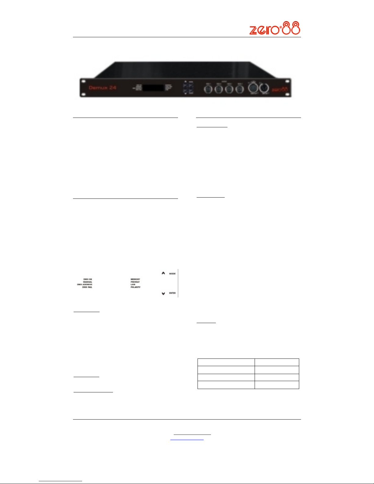
Control Interface
The main display consists of four seven-segment
displays; the data displayed is dependent on the setup mode of the Demux 24. Around the outside of
these displays are eight LED’s. Seven of which
indicate the current set-up mode of the Demux 24,
the eighth is used for DMX indication.
The Demux 24 has a default mode, for operation. In
this mode none of the set-up mode LED’s will be lit,
the main display will show the DMX address(es) and
if it has been terminated a small dot will be shown in
the bottom right of the fourth display.
Mode Button:
The Mode button is used to cycle through the
different set-up modes. They are;
- Manual
- DMX address
- DMX fail
- Memory
- Preheat
- Law
- Polarity
- Default
Enter Button:
The Enter button is used to confirm actions.
Up & Down Buttons:
These are used to adjust the values shown in the
main display. Pressing both buttons together will
reset the display to the default values.
Set-up Modes:
Manual Control:
The Manual Control Mode allows the user to set-up a
look on the outputs without the need of an external
controller.
Select ‘Manual’ mode using the ‘Mode’ button. The
display will show CC.LL, where CC is the channel
number and LL is the level. Select the channel you
require or ‘A’ for all channels, using the ‘Up & Down’
Arrows and press ‘Enter’. Now set the level you
require using the ‘Up & Down’ Arrows and press
‘Enter’ again to confirm and move back to the
channel selection.
DMX Address:
There are 2 ways that the Demux 24 can be patched
– a single DMX start address can be set for the block
of 24 channels (block patch), or each output socket
(6 channels) can be given a different DMX start
address.
For block patch, the range of DMX start addresses is
001 – 489. In default mode the single DMX start
address of the block will be shown on the display.
For individual patch, the range of DMX start
addresses is 001 – 507. In default mode all four DMX
start addresses are cycled on the display.
Select ‘DMX ADDRESS’ using the ‘Mode’ button, the
display will show S.AAA, where S is the socket
number and AAA is the current DMX address for that
socket. Select the socket you require (1-4), or ‘A’ for
all sockets (block patch), using the ‘Up & Down’
Arrows and press ‘Enter’. Now set the address you
require using the ‘Up & Down’ Arrows and press
‘Enter’ again to confirm and move back to the socket
selection.
DMX Fail:
There are three DMX fail modes available – ‘fade to
black’, ‘hold DMX’ and ‘fade to memory’.
Select ‘DMX Fail’ using the ‘Mode’ button. Using the
‘Up & Down’ Arrows select your preferred choice
from the list below;
Fail Mode
Main Display
Hold Last State
Hold
Fade to Zero
F 00
Fade to Memory 1 - 12
F 01 – F 12
Page 2
DEMUX 24 USER GUIDE
Zero88 Lighting Ltd, Usk House, Llantarnam Park, Cwmbran, Gwent NP44 3HD, U.K
Tel: +44 (0) 1633 838088 (24hr Answer Phone) Fax: +44 (0) 1633 867880
73-402-00 Email: sales@zero88.com
IM7752 Demux24 Manual Issue 1.0.doc www.zero88.com Page 2 of 3
Memories:
The Demux 24 will store 12 memories for stand alone
operation, these can only be re-called if there is no
DMX present.
1. Set-up the scene using the ‘Manual’
control function or a DMX controller.
2. Select ‘Memory’ using the ‘Mode’ button.
Using the ‘Up & Down’ Arrows select the required
memory number and press the ‘Enter’ button to
confirm. A ‘p’ should appear next to the memory to
signify that it has been programmed.
Holding both the ‘Up & Down’ Arrows for 1 second
will clear the selected memory. If these buttons are
held for 5 seconds, ALL memories will be cleared.
Preheats:
Preheats can be selected on a per channel or all
channel basis. The preheat level is preset to 5% and
cannot be adjusted.
Select ‘Preheat’ by cycling through the modes using
the ‘Mode’ button.
Select required channel or ‘A’ for all channels, using
the ‘Up & Down’ Arrows and press ‘Enter’, to confirm.
Now select on/off using the ‘Up & Down’ Arrows.
Press ‘Enter’ to confirm and return to the channel
selection.
Output Laws:
Three output laws are available, which can be
selected per channel.
Select ‘Law’ mode using the ‘Mode’ button. Using
the ‘Up & Down’ Arrows select the channel required,
or ‘A’ for all channels. Press ‘Enter’ to confirm. Now
select the law you require, again using the ‘Up &
Down’ Arrows and press ‘Enter’ to confirm and return
to the channel selection.
Output Law
Main Display
Normal
n
Switch
S
Linear
L
Polarity:
Each output socket can be set to positive or negative
voltage polarity.
Select ‘Polarity’ mode using the ‘Mode’ button.
Using the ‘Up & Down’ Arrows select the socket
required, or ‘A’ for all sockets. Press ‘Enter’ to
confirm. Now select the polarity (‘Pos’ or ‘Neg’) you
require, again using the ‘Up & Down’ Arrows and
press ‘Enter’ to confirm and return to the socket
selection.
Super User:
The Demux 24 has a number of hidden functions,
located in the Super User Menu. The super user
menu’s can only be accessed from the Default mode
(No LEDS Lit). To enter Super User press and hold
the ‘Up & Down’ Arrows together and press and hold
the ‘Mode’ button for 5 seconds. All the mode LED’s
will flash to indicate the Demux 24 is in super user
mode.
The ‘Up & Down’ Arrows are used to cycle through
the various super user functions. Pressing the ‘Mode’
button at any point will revert to normal operation. If
no buttons are pressed after 20 seconds the Demux
24 will automatically revert to normal operation.
Lock/Unlock
Press the ‘Up & Down’ Arrows until the display shows
“LOC”. Press ‘Enter’ to confirm this action. The
Demux 24 will revert to the Default mode. Pressing
the ‘Mode’ button now will only cycle between
Manual Control and Default Mode.
If Super User is entered when the Demux 24 is
locked, only the unlock function will be available. The
display will show “UNL”. To unlock the Demux 24,
press and hold the ‘Enter’ button for 5 seconds. The
Demux 24 will unlock and exit super user returning to
the Default mode.
DMX Termination:
Press the ‘Up & Down’ Arrows until the display shows
“ter”. If the Demux 24 is terminated a dot will appear
at the bottom of the last segment. Pressing the
‘Enter’ button will toggle between the two states.
Resetting The Demux 24:
Press the ‘Up & Down’ Arrows until the display shows
“rset”. Press ‘Enter’ to confirm. The display will flash
briefly to confirm this action. The Demux 24 will be
reset to its default settings, shown in the table below:
Set Up Parameter State
Manual Control Levels All Off
DMX Addresses Block patch at 001
DMX Fail Mode Hold Last State
Memory Memory Cleared
Preheat Off (0%) for all channels
Law
Normal law for all
channels
Polarity
Positive for all output
sockets
DMX termination Disabled
Firmware Version:
To identify which version of firmware is loaded in the
Demux 24, press the ‘Up & Down’ Arrows until the
firmware version is shown in the display (e.g. 01.00)
The ‘Enter’ button has no use here. (The firmware
version will also be shown briefly on start up).
CAUTION
TO AVOID POSSIBLE DAMAGE TO
EQUIPMENT, TAKE CARE TO MATCH THE
POLARITY SETTING ON THE DEMUX 24 TO
THAT REQUIRED BY CONNECTED
EQUIPMENT.
Page 3

DEMUX 24 USER GUIDE
Zero88 Lighting Ltd, Usk House, Llantarnam Park, Cwmbran, Gwent NP44 3HD, U.K
Tel: +44 (0) 1633 838088 (24hr Answer Phone) Fax: +44 (0) 1633 867880
73-402-00 Email: sales@zero88.com
IM7752 Demux24 Manual Issue 1.0.doc www.zero88.com Page 3 of 3
Servicing Functions:
There are three further modes available within Super
User, which are used for servicing and maintenance
purposes. It is strongly recommended that these are
only accessed by Zero 88 staff or an appointed
Zero 88 dealer. However, they can be accessed in
the same way as before, using the ‘Up & Down’
Arrows to scroll through the memories and ‘Enter’ to
activate.
The “leds” function tests the segment display.
Pressing ‘Enter’ for 1 second will activate the test.
When activated the displays will begin to cycle
through a series of patterns.
“rdt” is used to test the hardware for RDM
functionality. Pressing ‘Enter’ for second will activate
the test. RDM functionality has been implemented in
hardware, however the current firmware does not
support the extra functionality. This test checks that
the hardware is functioning correctly.
“upgr” is used to re-programme the Demux 24’s
firmware. This can only be done in the factory.
Technical:
Electrical:
The Demux 24 is designed to operate on the
following mains input specification. The Demux 24
may not operate satisfactorily outside this
specification.
- Mains Supply Voltage: 85-264V AC
- Frequency: 47 – 63 Hz
- Single Phase CEE22 inlet connector
Mechanical:
- Height: 44mm
- Width: 483mm
- Depth: 128mm
- Weight: 3.0kg (6.6lb)
Analogue Output Connections
- Four 8-pin ring-locking DIN connectors, six
channels each.
- Short circuit proof, all channels capable of 5mA,
diode output.
- Positive / Negative polarity by software selection.
- Any dimmer supply not used.
- Pin assignment is:
Pin 1 Channel 1 (7, 13, 19)
Pin 2 Channel 2 (8, 14, 20)
Pin 3 Channel 3 (9, 15, 21)
Pin 4 Channel 4 (10, 16, 22)
Pin 5 Channel 5 (11, 17, 23)
Pin 6 Channel 6 (12, 18, 24)
Pin 7 Not connected
Pin 8 0V
DMX Connections
One male and one female 5 pin XLR connector.
Opto-isolated. Pin assignment is:
Pin 1 0V
Pin 2 DMX- (RS485 B line)
Pin 3 DMX+ (RS485 A line)
Pin 4 Reserved
Pin 5 Reserved
DMX Indication:
On
DMX dimmer data (start byte of 00)
being received OK.
Flash Fast
DMX data being received, but not
dimmer data (start byte of 00)
Flash Slow DMX data errors occurring.
Off No DMX data being received.
Notes:
Zero 88 Lighting Ltd reserves the right to make
changes to the equipment described in this manual
without prior notice.
This equipment is designed for professional stage
lighting control, and is unsuitable for any other
purpose.
It should be used by, or under the supervision of, an
appropriately qualified or trained person.
E&OE. Zero88 Lighting Ltd reserves the right to
change the specification without prior notice.
Manual Stock Number: 7340200
Issue 1.0: July 2004
© Zero 88 Lighting Ltd 2004
WARNING
DO NOT REMOVE COVERS WITHOUT FIRST
COMPLETELY DISCONNECTING THE DEMUX
24 FROM THE MAINS SUPPLY.
 Loading...