

Zephyr W, S) Pyramid, Tamburo ZTA-E30S, Tamburo ZTA-E36S, Pyramid ZPY-E30B Use, Care And Installation Manual
...Page 1

USE, CARE, AND INSTALLATION GUIDE
Read all Instructions before Installing and operating this appliance
MODELS: ZPY-E30 (B,W,S), ZPY-E36 (B,W,S) Pyramid
WARNING
Installation
The installation in this manual is intended for qualified installers,service technicians or persons
with similar qualified background.DO NOT attempt to install this appliance yourself.Injury could
result from installing the unit due to lack of appropriate electrical and technical background.
All electrical wiring must be properly installed, insulated and grounded. Overly accumulated
grease in old duct work should be cleaned out or duct work should be replaced if necessary to
avoid the possibility of a grease fire. Check all joints on duct work to insure proper connection
and all joints should be properly taped.
Operations
Read all instructions in this manual before operating the appliance. Sa ve these instructions for
future reference.
Always leave safety grills and filters in place. Without these components, operating blowers
could catch on to hair, fingers and loose clothing.
NEVER dispose cigarette ashes, ignitable substances, or any foreign objects into blowers.
NEVER leave cooking unattended.When frying,oil in the pan can easily overheat and catch fire.
The risk of self combustion is higher when the oil has been used several times.
Cleaning
The saturation of greasy residue in the blower and filters may cause increased inflammability.
Keep unit clean and free of grease and residue build-up at all times to prevent possible fires.
Filters must be cleaned periodically and free from accumulation of cooking residue (see cleaning instructions inside). Old and worn filters must be replaced immediately. Do not operated
blowers when filters are removed.Never disassemble parts to clean without proper instructions.
Disassembly is recommended to be performed by qualified personnel only .Call our service cen-
ter for removal instructions.
The manufacturer declines all responsibility in the event of failure to observe the instructions given here for installation,maintenance and suitable use of the product. The manufacturer further declines all responsibility for injury due to negligence and the warranty of the
unit automatically expires due to improper maintenance.
IMPORTANT SAFETY NOTICE
* Please check for latest specification revisions before any custom work or cutouts.
Page 2

CONTENTS
INSTALLATION
Mount heights & clearance
Ducting
Specifications
Mounting the hood & electrical
FEATURES & CONTROLS
Controls & features
MAINTENANCE
Cleaning
Lights replacement
WARRANTY
Coverage & exceptions
1
1,2
3
4-7
8
9
10
11
Page 3

INSTALLATION
1
MOUNT HEIGHTS
DUCTING
6-3/4"
36"
96"
Min 24"-Max 32"
Minimum mount height between range top to
hood bottom should be no less than 24".
Maximum mount height should be no higher
than 32".
It is important to install the hood at the
proper mounting height. Hoods mounted too
low could result in heat damage and fire hazard; while hoods mounted too high will be
hard to reach and will loose its performance
and efficiency.
If available, also refer range manufacturer's
height clearance requirements and recommended hood mounting height above range.
A minimum of 5" round or 3-1/4” x 10"rectangular
duct must be used to maintain maximum air flow
efficiency.
Always use rigid type metal ducts only.
Flexible ducts could restrict air flow by up to 50%.
Also use calculation (on right) to compute total
available duct run when using elbows, transitions
and caps.
ALWAYS,when possible, reduce the number or
transitions and turns. If long duct run is required,
increase duct size from 6" to 7 or 8". If a reducer
is used, install a long reducer instead of a pancake
reducer. Reduce duct size as far away from opening as possible.
If turns or transitions are required:
Install as far away from opening and as far
apart, between 2, as possible.
*Minimum clearance of 24”hood above range
height.
** Maximum clearance 32" hood above range
height.
Minimum Duct Size:
Round:
5" minimum
Rectangular:
Requires an adaptor.Readily available at most
hardware stores.
Duct Run Calculation:
Maximum run
5" or 3-1/4” x 10" duct
Deduct:
each 90 Elbow used
each 45 elbow used
each 6" to 3/14 x 10"
transition used
each 3/14 x 10" to 6"
each 3/14 x 10" to 6"
transition used
Side Wall Cap w/ damper
Roof Cap
100 FT
15 FT
9 FT
1 FT
5 FT
30 FT
30 FT
e.g.- 1 roof cap, 2x90 elbows, 1 45 elbow used:
=30' + 30' + 9' =69' used, 31' available for straight duct runs.
Page 4

INSTALLATION
2
DUCTING
NEVER exhaust air or terminate duct work into spaces between walls, crawl spaces, ceiling,a ttics or
garages.All exhaust must be ducted to the outside.
Use Metal ductwork only.
Fasten all connections with sheet metal screws and tape all joints w/ certified Silver Tape or DuctTape.
Some Ducting Options:
WARNING FIRE HAZARD
side wall cap
w/ gravity damper
side wall cap
w/ gravity damper
Soffit or crawl space
Roof Pitch w/
Flashing & Cap
Page 5

INSTALLATION
3
SPECIFICATIONS
10-1/2"
19-3/4"
6-3/4"
30"or 36"
5-1/2"
1/2" Elec. K.O.
5"
1"
4"
9"
2-5/8"
3/4"
1/4" to 4"
4-1/8"
3" (6" on 36" models)
Page 6

INSTALLATION
4
MOUNTING THE RANGEHOOD
ELECTRICAL
All Electrical work must by performed by qualified electrician or person with similar technical
know how and background.
For personal safety, remove house fuse or open circuit breaker before beginning installation.
Do not use extension cord or adapter plug with this appliance.
Follow National electrical codes or prevailing local codes and ordinances.
Electrical Supply:
This appliance requires a 120V 60Hz electrical supply.,and connected to an individual, properly
grounded branch circuit, protected by a 15 or 20 ampere circuit breaker or time delay fuse.Wiring
must be 2 wire w/ ground. Please also refer Electrical Diagram labeled on product.
Cable Lock:
A cable locking connector (not supplied) might also required by local codes. Check with local
requirements and codes, purchase and install appropriate connector if necessary.
Cable Lock
WARNING
Page 7
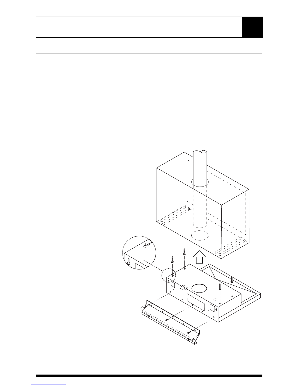
INSTALLATION
5
MOUNTING THE RANGEHOOD
1.This range hood is mounted under a
kitchen cabinet unit.
2. Select preferred duct location on rear or
top of unit. For ductless conversion, no
ducting is required.
3.An optional spacer plate is provided to
cover the gap between the back of the
hood and the wall. If using this plate,
screw it onto the hood prior to installation.
4. Begin installation by temporarily removing
the filter panels.
5.Temporarily position the range hood in
the desired mounting location.
6. Mark the mounting holes, duct and
electrical access locations with a pencil.
For ductless conversion,no hole is required
for a duct.
7.Drill/cut out the required openings for duct
and electrical access.
8.Install duct work and electrical.
Page 8

INSTALLATION
6
MOUNTING THE RANGEHOOD
9. Fasten mounting screws into
underside of mounting location,
and reposition hood into place.
10. Hang hood onto mounting screws and
hand tighten.
11. For ductless conversion, the interior cover
plate must be unscrewed, repositioned
and re-screwed into alternate position
as shown.
12. Reinstall the filter panels.
Cover panel position
for duct exhaust
Cover panel position
for ductless conversion
Page 9
INSTALLATION
7
DUCTLESS CONVERSION
Ductless conversion is intended for applications where an exhaust duct work is not possible to be
installed.When converted, the hood functions as a "purifying" hood rather than an exhaust hood.
Fumes and exhaust from cooking is drawn and filtered by a set of optional Carbon Filters.The air
is then purified and re-circulated back within the home.
We recommend to ALWAYS exhaust air outside of the home by employing existing or installing
new duct work, if possible.The hood is most effective and efficient as an Exhaust unit. Only when
the exhaust option is not possible should you recourse to converting the hood into a "purifying"unit.
When converted to be a "purifying" unit, a set of Carbon Filters are required on top of its standard
Metal Filter set.Order according to its Part number below.The standard Metal Filters are intended
to capture residue from cooking and the optional Carbon Filters help to purify fumes exhausted
from cooking for re-circulation.
Carbon Filters (Required)
1. Purchase ductless Charcoal Filters as follow:
2. Remove metal filters on hood.
3. Install attachment bracket into metal filter.
4. Clip carbon filter onto bracket.
5. Re-install metal filters.
6. Carbon Filters must be replaced after
every 120 hours of use (or approximately
every 2 to 3 months based on the average
of 1-2hrs. of daily cooking time).
Hood Model: Part No. Filters in pkg.
ZPY-E30 (B, W, S) ZOF-CO22 2
ZPY-E36 (B, W, S) ZOF-CO23 3
Page 10

CONTROLS & FEATURES
8
CONTROLS & FEATURES
Lights On/Off
1
Speed Selection
2
Speed Selection
Lights On/Off
2
1
This switch controls the speed of the blower.The first position is low speed, the second is
medium speed, and the third is high speed.
Turn lights on or off by moving this switch.
Page 11

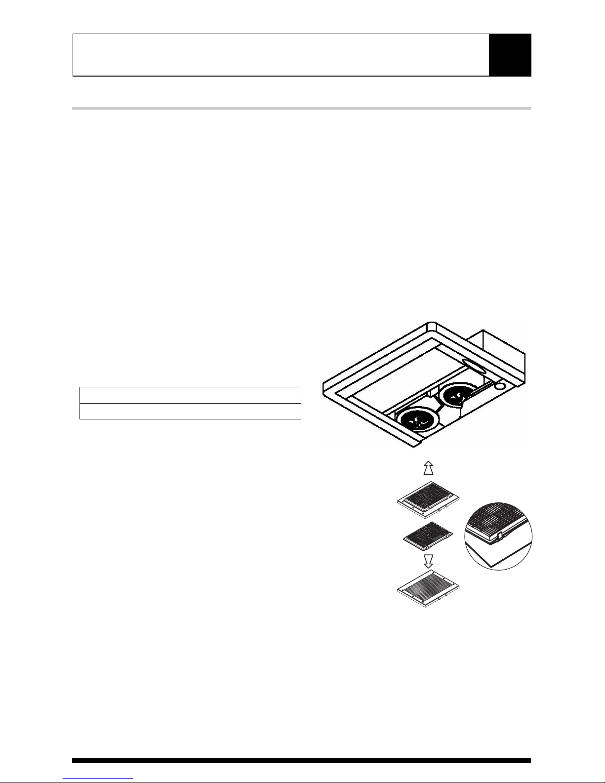
MAINTENANCE
9
CLEANING
Surface Maintenance:
Clean periodically with hot soapy water and clean cotton cloth.Do not use corrosive or abrasive
detergent (e.g. comet powder scrub, EZ-Off oven cleaner), or steel wool/scoring pads which will
scratch and damage surface.
For heavier soil use liquid degreaser such as 'Formula 409' or 'Fantastic' brand cleaner.
After cleaning,you may use non abrasive stainless steel polish/ cleaners such as 3M or
ZEP, to polish and buff out the stainless luster and grain.Al ways scrub lightly,with
clean cotton cloth,and with the grain.
Metal Filters
The Metal Filters fitted by the factory are
intended to filter out residue and grease
from cooking. It need not be replaced on a
regular basis but are required to be kept clean.
Filters should be cleaned after every 30
hours of use.
Remove and clean by hand or in
dishwasher. Spray 'Formula 409' or
equivalent degreasing detergent and leave
to soak if heavily soiled.
Dry filters and re-install before using hood.
Replacing Metal Filters
Should filters wear out due to age and
prolonged use, replace with following part
number:
Also replace damaged filter that has
punctured or broken mesh, bent or broken frame.
Hood Model: Part No. Filters in pkg.
ZPY-E30 (B, W, S) ZOF-MO32 2
ZPY-E36 (B, W, S) ZOF-MO33 3
Page 12

MAINTENANCE
10
LIGHTS
Replacing Light Bulbs
Make sure all power is turned off and
bulbs are not hot.
Remove by turning bulb counter
clockwise.
If bulbs are difficult to turn due to
prolonged use, firmly attach a glass
suction cup approx. the diameter of the
bulb and turn.
Replacement bulbs are available at
specialty lighting stores. Purchase type
JDR E27 50W halogen bulbs.
Or to order bulbs, please call our service
center: 888-880-8368 or online parts store:
www.zephyronline.com
CAUTION: Light bulb becomes extremely hot when turned on.
DO NOT touch bulb until switched off and cooled. Touching hot
bulbs could cause serious burns.
Page 13
WARRANTY
One Year Service Repair Warranty:
For one year from date of original purchase, we will provide free of charge, service labor to repair
any failed parts or components due to manufacturing defects.
Two Years Parts Warranty:
For two years from date of original purchase, we will provide free of charge, nonconsumable
replacement parts or components that failed due to manufacturing defects.
Consumable parts not covered by this warranty include:Light Bulbs, Metal and Carbon Filters.
Who is Covered:
This warranty is extended to the original purchaser for products purchased for ordinary
home use in the 48 mainland states, Hawaii and Washington D.C.
In Canada and Alaska, this warranty is Limited. There might be costs associated with shipping
the products to our designated service locations or you might need to pay ser vice technician's
travel costs, to have the appliance repaired in-home.
This Warranty will be Voided when:
Product damaged through negligence, misuse, abuse, accident.
Improper installation and failure to follow installation instructions. When product is used
commercially or other than its intended purpose.
Damaged because of improper connection with equipment of other manufacturers.
Repaired or modified by anyone other than Zephyr's Authorized Agents.
What is Not Covered:
Consumable parts such as light bulbs, filters, and fuses.
Services outside of service area and the labor cost incurred in connection with the removal,
shipping and reinstallation cost, nor does it cover any other contingent expenses.
The natural wear of finish, and wear due to improper maintenance, use of corrosive and
abrasive cleaning products,pads, and oven cleaner products.
Chips, dents or cracks due to abuse, misuse, freight dama ge, or improper installa tion.
Service trips to your home to teach you how to use the product.
Damage of product caused by accident, fire, floods or act of God.
This warranty is valid in the United States and Canada. It is non-transferable and applies only to the original purchaser and
does not extend to subsequent owners of this product. Any applicable implied warranties, including the warranty of merchantability,are limited in duration to a period of express warranty as provided herein beginning with the date of original purchase at retail and, no warranties, whether express or implied, shall apply to this product thereafter.
TO OBTAIN SERVICE UNDER WARRANTY:
You must present proof of original purchase date.
Please keep a copy of your dated proof of purchase (sales slip)
in order to obtain service under warranty.
11
Page 14

1-888-880-8368
Have your product proof of purchase with date ready for warranty issues.
Or write to:
Zephyr Corporation
Service and Warranty Department
395 Mendell Street
San Francisco, CA 94124
TO OBTAIN SERVICE UNDER WARRANTY
or any Service Related Questions, please call:
 Loading...