

Page 1
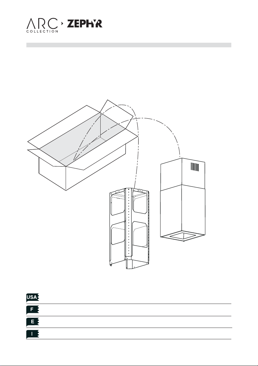
Duct Cover Extension
Z1C-00SL
For use with Surface Is. range hood
customer service
1.888.880.8368
Mounting the duct cover Pag. 4
Fixation des cheminees Pag. 6
Fijación de las chimeneas Pag. 8
Fissaggio dei camini Pag. 10
Page 2
www.zephyronline.com
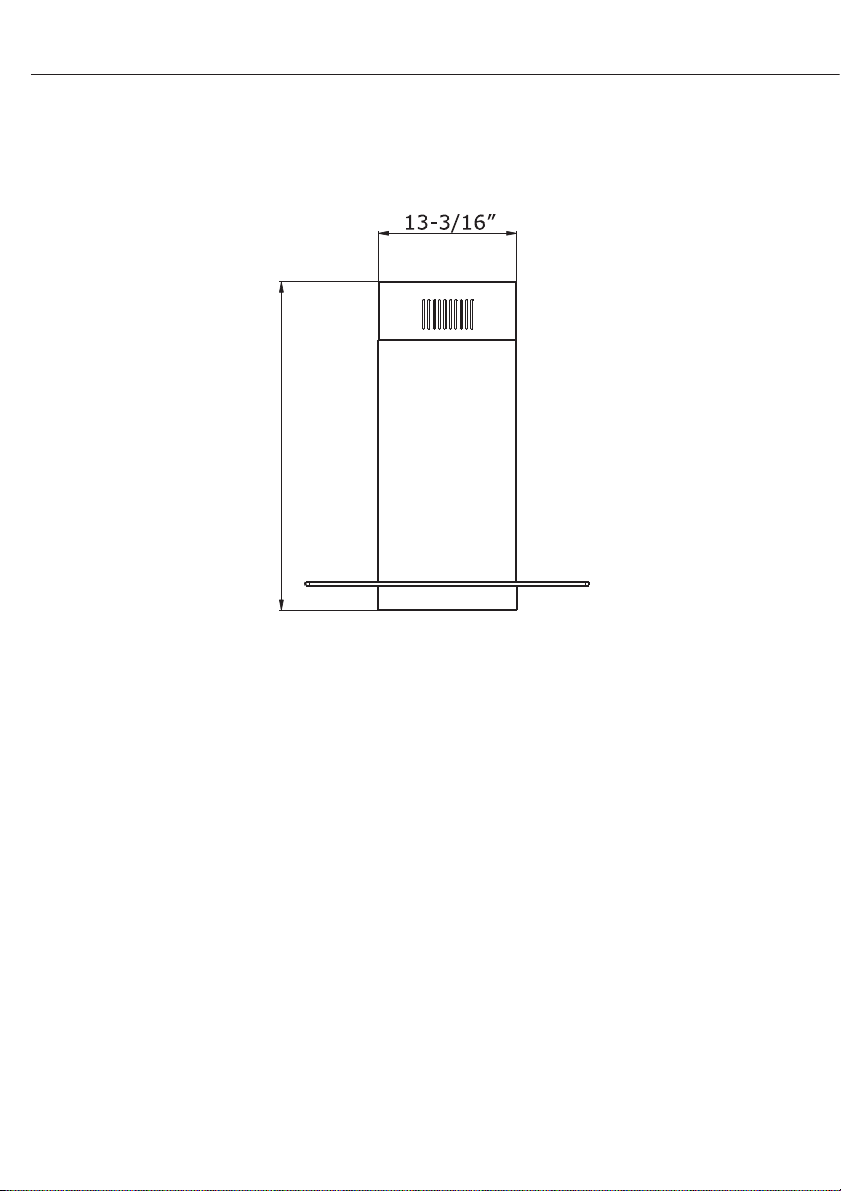
DUCT COVER EXTENSION SPECIFICATION
Min. 47-3/16" - Max. 79"
- 2 -
Page 3

MOUNTING THE DUCT COVER
1. Before installing the duct cover extension kit, take out the duct cover ceiling bracket fom the range hood packaging and remove the bracket by unscrewing the (4)
screws.
2. Remove the duct cover from the hood assembly, according to the following steps:
A - Take out the lower mantle by removing the (7) screws. Fig. 1
B - Take out the spacer, by removing the (6) plus (4) metric screws and the bushes.
Fig. 2
C - Take out the two additional bushes that secure the glass. Fig. 3
3. Take the lower duct cover from the duct cover extension kit and secure it to the
hood assembly by following the instructions from step 2 in reverse order.
- 3 -
Installation - Mounting the Duct Cover
Page 4

www.zephyronline.com
4. Remove the (2) screws to unlock the top support frame from the bottom support
frame. Fig.4.
5. Secure the top support frame to the duct
cover ceiling bracket by using the (4)
screws. Fig. 5
6. Position hole template on the ceiling paying
attention that the arrow is positioned on
the same side as the range hood controls.
- Make 4 holes in the ceiling and drive in (3)
screws without completely tightening
them. Pay attention not to insert the screw
into the hole marked with an X on the hole
template. Fig.6
7. Lift the hood assembly to the ceiling and
align the top support frame and ceiling bracket with the (3) screws previously installed
in the ceiling.
Rotate assembly slightly clockwise to lock in
place.
Drive in the fourth screw and tighten the re-
maining 3 screws to secure the structure in
place with con ulteriori (4) viti. Fig.6
Installation - Mounting the Duct Cover
8. Insert the bottom support frame into the
top support frame. Fig.7
- 4 -
X
C
B
X = C - (5-1/2" + 24" + B)
5 - 1/2"
24"
Page 5

Adjust height by referring to the diagram in g.8.
Secure the support frames together using (2)
screws per extension arm (8 total). Fig.9
9. Insert the motor housing into the support frame
assembly and secure it using (8) screws. Fig.10
10. Connect the equipment to the power supply.
11. Secure the correct size ducting for your instal-
lation (not supplied) to the collar on top of the
housing. Fig.11
12. Extend upper duct cover to the ceiling and
secure it to the duct cover ceiling bracket using
the (4) screws previously removed when the assembly was taken out of the packaging. Fig. 12
13. Lift the hood assembly into the top duct cover.
Secure hood assembly to bottom support frame by using
(4) screws. Fig. 13
14. Verify that ducting from hood is connected to ducting
in the attic that will exhaust air out of the home.
- 5 -
Installation - Mounting the Duct Cover
Page 6

3FA0174
 Loading...