

Page 1

USE, CARE AND INSTALLATION GUIDE
Read all instructions before installing and operating this appliance
IMPORTANT SAFETY NOTICE
WARNING
Installation
The installation instruction in this manual is intended for qualified installers, service
technicians or persons with similar qualified background. DO NOT attempt to install this
appliance yourself. Injury could result from installing the unit due to lack of appropriate
electrical and technical background.
All electrical wiring should be properly installed, insulated, and grounded. Overly
accumulated grease on old duct work should be cleaned out or duct work should be
replaced if necessary to avoid the possibility of grease fire. Check all sections and joints
on duct work to insure proper connection and all joints should be properly taped.
Operations
Read all instructions in this manual before operating the appliance. Save these
instructions for future reference.
ALWAYS leave safety grills attached in place at all times. Operating blowers could catch
on to hair, fingers, and loose clothing.
Keep unit and residue containers clean from grease accumulation from time to time.
NEVER dispose foreign substances into the blowers. Do not dispose cigarette ashes or
ignitable substances into the blowers.
Cleaning
Use with extreme caution while performing the Self Cleaning Function and safety grills
are removed. Beware of fingers, hair, loose clothing from getting in the blowers and
NEVER leave children unattended.
NEVER disassemble parts to clean without proper instructions. Disassembly are
recommended to be performed by qualified personnel only. We are not responsible for
injury due to negligence and the warranty of the unit automatically expires due to
improper maintenance. Call our Service Center for removal instructions.
Page 2
1
HURRICANE SERIES
CYCLONE SERIES
WHIRLWIND SERIES
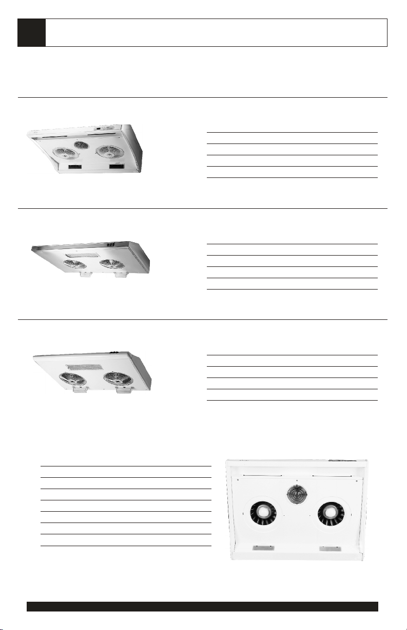
PRODUCT OVERVIEW
Model number: AK2000, 2036
, QuattroVent Air Curtain
, Dual “Thrust-Fore" Self Clean Blowers
, Digital Touch Pad Controls
, Clock, Timer, 3 stage Delay Shutoff.
Model number: AK6000, 6036, 6042, 6048
, Dual “Thrust-Fore" Self Clean Blowers
, Independent Rocker Controls w/ High, Low
speed
, 3 Way convertible ducting option
Overview
1. QuattroVent Air Curtain
(Hurricane only)
2. Self Clean Blowers
3. Controls
4. Light
5. Residue Cup
6. Underside splash guard
Model number: AK9200
, Dual Self Clean Blowers
, Independent Rocker Controls w/ High, Low
speed
, Slim Line Design
3
1
4
2
6
5
Page 3
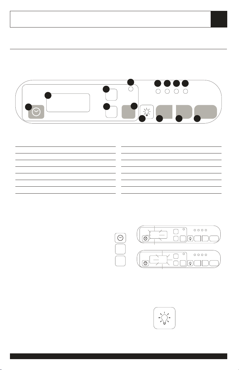
HURRICANE SERIES
CONTROLS
2
2
1
12:01
Controls Overview
1. Set Time
2. Digital Display
3. Set Hours
4. Set Minutes
5. Set Timed Delay Shut Off
6. Light On-Off
7. Left Blower: On-High-Low-Off
Setting Clock
Press "clock".
Hour Indicator will flash indicating clock
setting function is ready.
Press "hr" to set hours (from 1-12).
Press "min" to set minutes (from 00-59).
14
3
hr hr
4
minmin
DELAY
OFF
5
LO LO
HI HI
FAN-L
6 7 8 9
8. Right Blower: On-High-Low-Off
9. Operations: On-Off
10. Right Blower Low Speed Indicator
11. Right Blower High Speed Indicator
12. Left Blower Low Speed Indicator
13. Left Blower High Speed Indicator
14. Delay Off Indicator
press:
12:01
hr hr
minmin
12:01
FAN-R
hr hr
DELAY
minmin
hr hr
DELAY
minmin
10111213
ON-OFF
LO LO
HI HI
FAN-R
ON-OFF
FAN-L
OFF
LO LO
HI HI
FAN-R
ON-OFF
FAN-L
OFF
Let clock flash for 7 seconds and your new
time input will automatically be stored.
Light On-Off
Press "light" button once to turn light on.
Press again to turn off.
press:
to turn light On/Off
Page 4
3
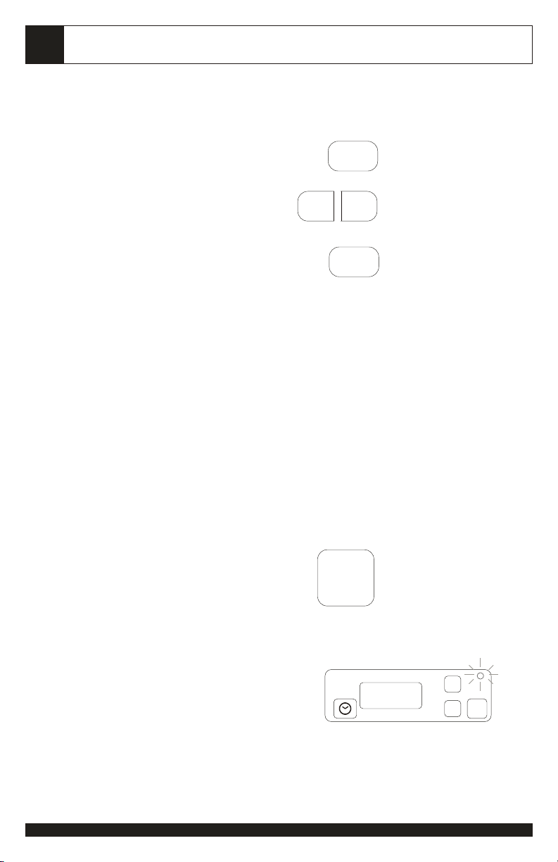
Blower Controls
CONTROLS
You can simultaneously turn On the light and
both blowers on Hi speed by simply pressing
"On/Off" once.
During this time, you can select blowers and
speed as indicated by pressing the "Fan-L"
and "Fan-R" button.
Note:
The third press on the "Fan-L" and "Fan-R"
button will turn blower Off the selected side (as
indicator light turns off).
You can also turn individual blowers On/Off
and select speed by simply pressing the
desired "Fan-L" or "Fan-R" button.
Press "On/Off" again and all operations will
stop.
Timed Delay Off
While blowers are in operation, pressing
"Delay Off" button once will set the unit to
turn off in 3 minutes. Press again for the
preset 5 minutes countdown and third
press for 10 minutes.
Once a desired time is selected,
countdown will start as the delay off
indicator light flashes. All operation will
cease as the countdown reaches zero.
Note: At any time when the delay function
is selected, the light will turn off
automatically and all blower will decelerate
to Lo speed.
press:
FAN-L
press:
indicator:
ON-OFF
FAN-R
ON-OFF
DELAY
OFF
to turn light and both
blowers on Hi
or turn individual blowers
On/Off and select Hi/Lo speed
press again to turn all
operations Off
once- countdown in 3 minutes
twice- in 5 minutes
3rd time- in 10 minutes
Light will turn off when pressed
and blowers will decelerate to
Lo speed.
hr hr
3
DELAY
minmin
OFF
Page 5
Setting Timer (Alarm)
CONTROLS
4
Press "hr" and "min" button to set desired timer
countdown.
Once timer is set, countdown will start in 7
seconds as delay indicator light flashes.
When countdown reaches 0, 10 short beeps will
sound.
To cancel timer after setting, press "On/Off"
button to terminate all operations and restart.
Note: Timer function cannot be operated
simultaneously with the "Delay Off" function.
Nevertheless, setting the timer function will not
effect any other operations.
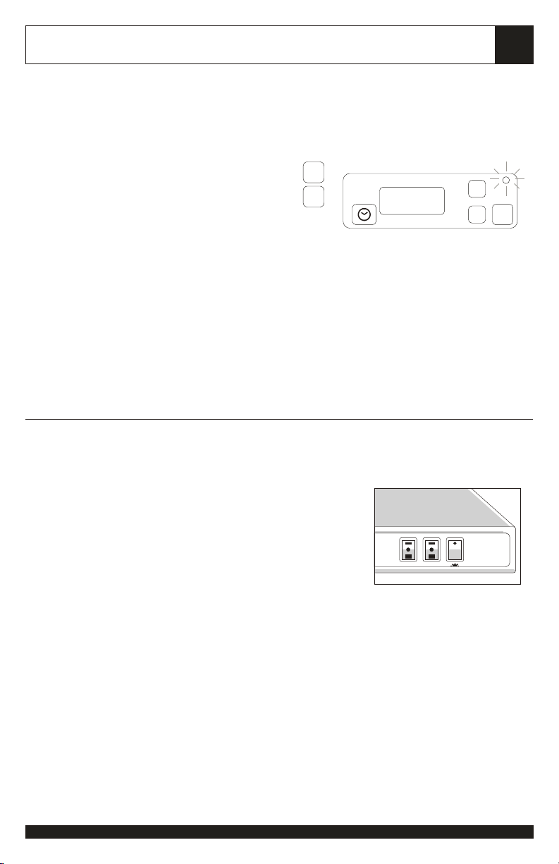
CYCLONE & WHIRLWIND
Rocker Controls
(1) Light- turns light On/Off
(2) (3) Blower Controls- Independently controls
Right and Left blowers. Rock switch up (I) for
Lo speed, (II) for Hi speed, and center (.) to
turn off.
press:
hr hr
minmin
set "hr" & "min" for timer countdown
alarm will sound at end of timer
(1) Light On/Off
(2) Right Blower
(Hi/Lo, Off)
(3) Left Blower
(Hi/Lo, Off)
1:04
R
L
hr hr
DELAY
minmin
OFF
123
Page 6
5
MAINTENANCE
Self Clean Feature
All Zephyr Range Hoods are filter-less and are designed with a self clean feature. The
centrifugal blower system automatically liquefies grease accumulated in its internal housing.
All systems are equipped with dishwasher safe grease containers for its self clean function.
Grease and residue from cooking are often automatically liquefied and can accumulate in the
containers from everyday use. Nevertheless, grease from cooking could also dry and
adhered in its internal housing. Running the self clean function periodically will flush out the
accumulated grease in the range hood’s internal housing.
Cleaning Frequency
Cleaning should be approximately once a month under normal use.
Detergent
Grease cutting detergent such as ‘409’ or its equivalent are recommended.
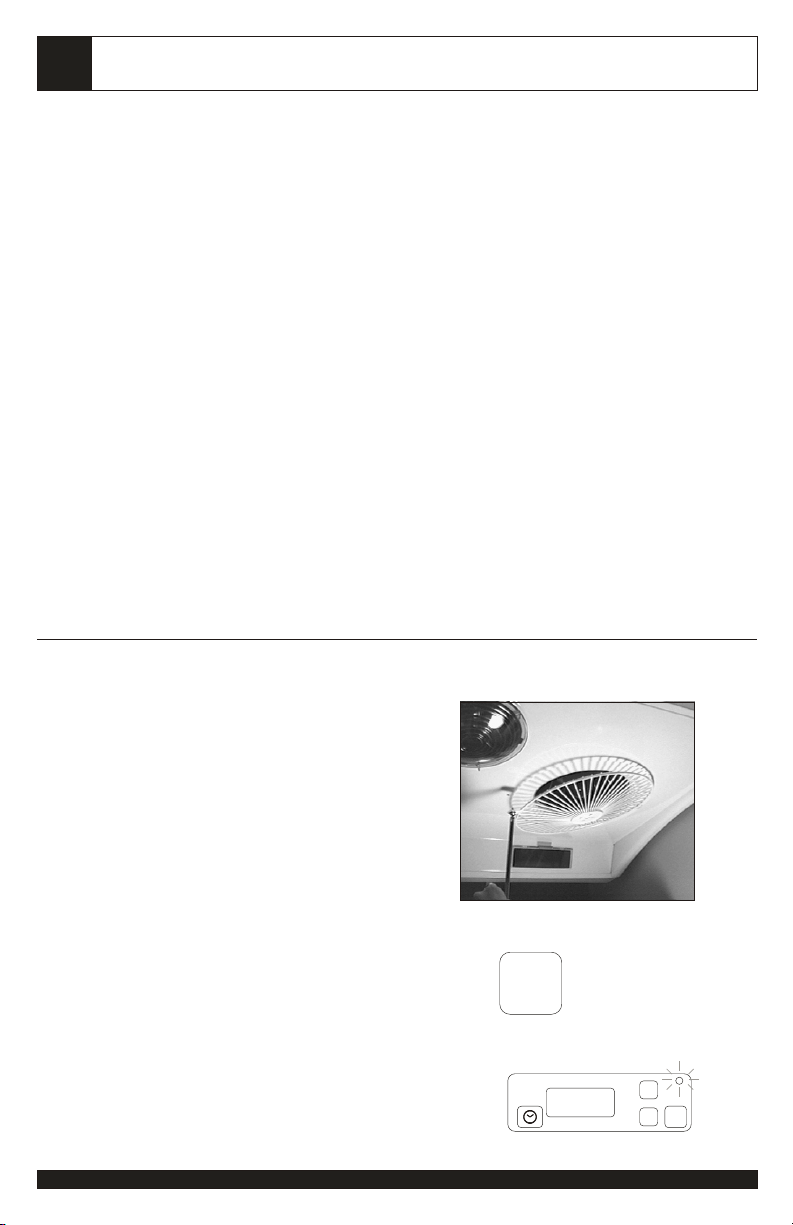
Cleaning
Safety Grill
Remove both safety grills for cleaning by
simply loosening Philips screws. Clean safety
grills in dishwasher under normal wash cycle.
WARNING: Use with extreme caution as both
safety grills are removed. Beware of blowers
catching on to hair, loose clothing, and fingers.
NEVER leave children unattended.
Self Clean
Turn both blowers on Low speed for cleaning.
For Hurricane series, simply set Timed Delay
Off to 5 minutes as indicated.
press:
indicator:
DELAY
OFF
twice- countdown in 5
minutes
hr hr
5
DELAY
minmin
OFF
Page 7

MAINTENANCE
With nozzle on ‘spray’, squirt ‘409’ detergent
directly onto blower blades 30-35 times.
Repeat with second blower. Allow self
cleaning to run for 5 minutes before switching
off. (If desired, spray water to rinse off detergent after
completion of the cleaning cycle and run for another few
minutes)
Remove residue containers by gently sliding
out with both hands. Clean in dishwasher
under normal wash cycle.
Hurricane Series:
Remove light shield by turning counterclockwise.
Clean in dishwasher under normal wash cycle.
6
Whirlwind Series:
Remove light shield by unscrewing Philips
screw.
Clean in dishwasher under normal wash cycle.
Cleaning Tip:
Fill residue containers ¼ full with water before cleaning or during regular use. This will
help to prevent grease from drying and tacking on cup surface.
Warning:
Edges on stainless steel surface are exposed once shield is removed. Clean around
edges with extreme care and we recommend the use of latex cleaning gloves.
Page 8

7
QuattroVent Channels
The QuattroVent Air-Curtain channels are
adjoined to its two main blowers and share the
same internal housing. No further cleaning is
required after the self clean is completed.
Clean residue around the channels surface
with ‘409’ and a cotton cloth regularly.
Surface Maintenance
Clean all surface residue with ‘409’ or mild detergent and wipe with a cotton cloth.
Stainless steel surface could further be polished with any stainless steel polish or glass
cleaners.
Replacing Lights
All light bulbs included are 40W appliance bulb. Replace with 60W bulbs if brighter
illumination are desired. Remove light shield according to instructions on page 6.
Warning: Edges on stainless steel surface are exposed once shield is removed. Replace
bulb through opening with extreme care. We recommend wearing of latex gloves.
MAINTENANCE
Page 9
INSTALLATION
WARNING
Installation of this product is intended for qualified installers, service technicians, or
persons with similar qualified background. DO NOT attempt to install this appliance
yourself. Injury could result form installing the unit due to lack of appropriate electrical
knowledge and technical background. Improper installation, adjustment, alteration,
service or maintenance can cause injury or property damage and the warranty on the
product automatically becomes void.
Installation of this product must conform with all local codes. All connections must be
electrically grounded and ducting must be properly vented outside in accordance to
codes. Never duct exhaust into attics, within walls, crawlspaces, garages, or anywhere
inside the house which might cause grease fire. All duct joints must be properly
inspected, taped and sealed.
Edges are exposed around the duct opening and once the bottom grease shield is
removed. Be careful when handling the sharp edges. Wearing protective gloves and
appropriate work clothing is recommended.
REQUIREMENTS
8
Duct Size
Hurricane- 6“ Vertical Duct Discharge
Whirlwind- 6“ Vertical Duct Discharge
Cyclone- 6“ Vertical Duct Discharge
3-1/4 x 10“ Vertical Duct Discharge
3-1/4 x 10“ Horizontal Rear
Discharge
ACCESSORIES
Hurricane & Whirlwind series
2 residue cups
2 ‘L’ brackets (for direct wall mount
only)
4 screws for ‘L’ brackets
1 6“ starting collar
3 electrical wire connectors & screws
Cyclone series
2 residue cups
2 ‘L’ brackets (for direct wall mount
only)
4 screws for ‘L’ brackets
Tools
Hand Drill with #2 philips
Flat head screwdriver to pry electrical knockout
3/4“ Wood Boring Bit
Jigsaw (if cabinet opening modification is
required)
Power Source
115W
1 6“ starting collar
3 electrical wire connectors & screws
1 Convertible transition collar
1 6“ collar cap
1 3-1/4 x 10“ starting collar (packaged
separately)
1 Back-splash
Check all accessories before installation, packaging also
includes 1) Care, Maintenance and installation manual
2) Owner’s Warranty Registration Card 3) Serial number
label adhered on top of box.
Page 10
9
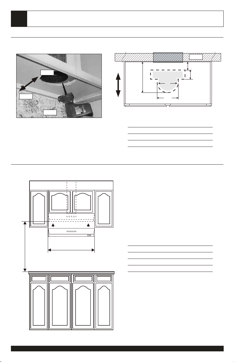
DUCT OPENING
Front
INSTALLATION
Rear
(A)
Wall
2-1/2”
4-1/2”3-1/4 x 10”
6”
Rear
Wall
CLEARANCES
MIN. 18” MAX 30”
net width
Front
7”
Cut Out Size (A):
Hurricane 10-1/2“
Cyclone 10-1/2”
Whirlwind 8-1/2”
Minimum clearance above range should be no
less than 18“ from the range surface to the
range hood’s base. Maximum height are
recommended not to exceed 30” for maximum
efficiency.
Net width on all models are call out width less
1/4”.
Call Out Size Net Width
30“ 29-3/4”
36“ 35-3/4”
42“ 41-3/4”
48“ 47-3/4”
Note: Refer Manufacturers’ height clearance
requirements on all high btu and professional
ranges.
Page 11

INSTALLATION
10
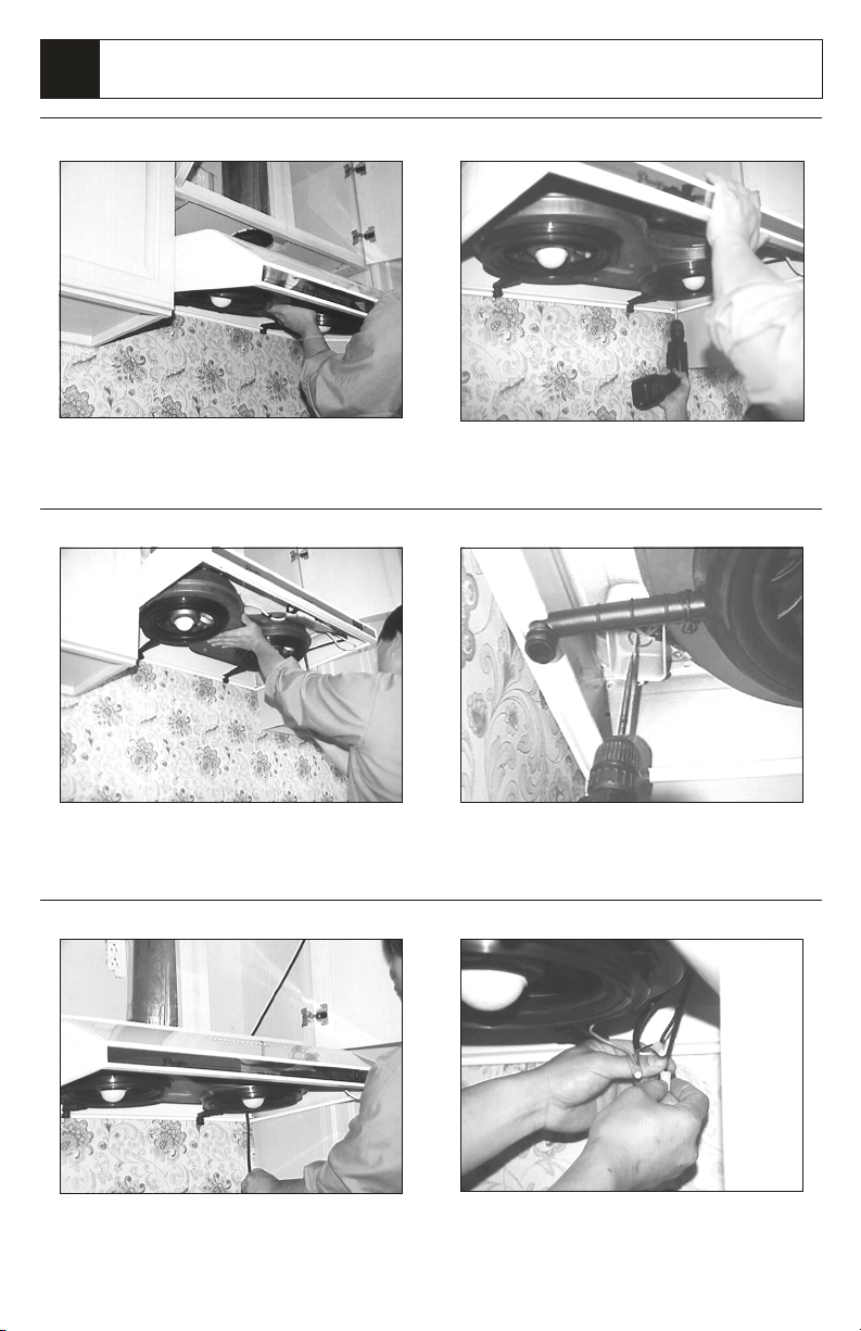
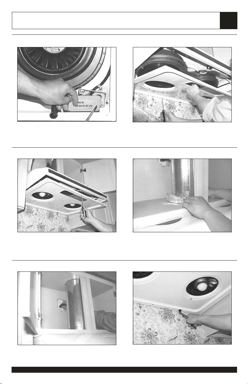
STEP 1
1. Remove all contents from box
2. Unscrew and remove bottom grease splash shield
STEP 3
STEP 2
1. Locate electrical connection box inside
2. Unscrew cover to reveal wiring
STEP 4
1. Locate electrical connection box knock out from left
rear of hood and pry open with screwdriver
STEP 5
1. Reinforce cabinet base with 1x2 wood strips if
additional strengthening is required.
2. Unscrew and remove bottom grease splash shield
1. Cut out cabinet base opening if necessary. Refer
cut out dimensions previous page.
STEP 6 (also refer notes on pg. 16)
1. Install damper if required by local codes (not
provided), or install 6“ starting collar (green)**
Page 12
11
INSTALLATION
STEP 7
1. Lift hood to bottom of cabinet
STEP 9 (also refer notes on pg. 16)
STEP 8
1. Support hood to place, fasten both rear with screws
and washers provided.
STEP 10
1. Fasten front of hood. Level all sides and adjust
accordingly.**
STEP 11
1. Pull electrical supply wire through drill out or use
#14 grounded wire for receptacles (not supplied)
1. Drill out cabinet base through electrical box with
3/4" boring bit.
STEP 12 (also refer notes pg. 16)
1. Connect both wires (blk) on hood to either power
supply (blk or wht). Ground green wire.**
Page 13
INSTALLATION
12
STEP 13
1. Reinstall electrical box cover.
STEP 15
STEP 14
1. Reinstall bottom splash shield by first fastening 3
rear screws, (do not tighten all the way).
STEP 16
1. Next, fasten the 3 front screws and begin tightening
all screws from rear to front.
STEP 17
1. Turn on electrical supply or plug into receptacles.
1. Connect duct to opening, inspect and tape all joints
with approved aluminum or duct tape.
STEP 18
1. On Cyclone & Whirlwind models, be sure to pull
both grease tubes over its opening.
Page 14

13
INSTALLATION
CONVERTIBLE OPTIONS
Cyclone series: AK6000, 6036, 6042, 6048
Zephyr’s Cyclone series are equipped with the option of a 6“ vertical discharge, 3-1/4x10” vertical discharge, or 31/4x10” rear discharge. Additional accessories are provided to convert to either of the above discharge methods.
Convertible Options
Vertical discharge 6“ round
Vertical discharge 3-1/4 x 10“
Horizontal rear discharge 3-1/4 x 10”
Back Splash
Cyclone models also come with a standard back splash. If desired, install back splash to rear of range hood with
screws provided after all duct conversion steps below are completed.
Convertible Accessories
6“ round duct cap
Round to rectangular transition adaptor
Rectangular to round transition adaptor (pre-
mounted)
Gasket (pre-mounted)
Rectangular rear cap (pre-mounted)
3-1/4 x 10“ starting collar
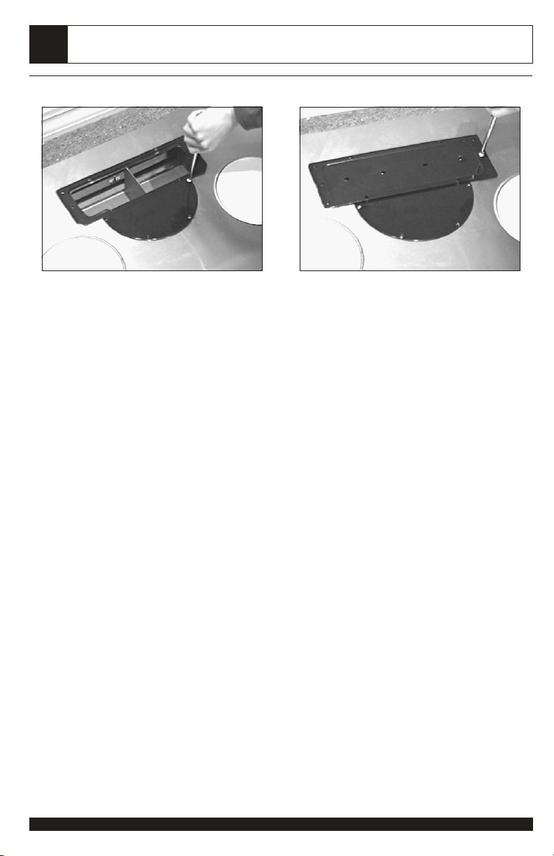
3-1/4 x 10“ Vertical Discharge
1. Remove pre-mounted 6“ transition adaptor on duct
opening. Leave attached gasket in its original place.
3. Mount the 3-1/4 x 10“ starting collar on top of
transition piece with remaining screws.
2. Place rectangular transition adaptor as shown over
gasket and by first installing 4 screws on half round
section.
Page 15

INSTALLATION
3-1/4 x 10“ Rear Discharge
14
4. At rear of range hood, remove all screws on premounted rear rectangular cap and remove cap with
gasket.
6. Remove 2 arch blocks through top opening.
5. Remove top pre-mounted transition piece. Leave
attached gasket in its original place.
7. Mount Starting Collar (provided) at rear discharge
opening with gasket previously removed.
Option 1: (for recessed cabinet base)
Re-install originally pre-mounted round transition
piece at opening with gasket.
Cap opening with 6“ cap provided OR, use option 2 if
cabinet base is not recessed.
Page 16
15
3-1/4 x 10“ Rear Discharge
INSTALLATION
Option 2: (for flush cabinet base)
Mount rectangular transition piece at opening with
gasket as shown.
Mount rectangular cap (previously removed) on top of
transition adaptor.
Page 17

INSTALLATION
INSTALLATION NOTES
Step 6:
A damper (not included) should be installed to prevent back-draft where needed. A damper might also be required
local codes in order to qualify for building inspections. You can purchase dampers from most hardware stores, or call
our service line to order.
When a damper is not installed, a starting collar is provided in order to increase and raise the duct opening clearance
above the cabinet's base. Snap the adaptor's smaller end to hood's duct opening and secure by drilling 2 pilot holes
and fasten with screws (as shown on step 6, page 10).
Step 9:
The hood should NEVER be installed so that the front is
tilting downward. This will cause grease to back flow to the
front instead of the rear. ALWAYS level the hood or slightly
tilt front of hood upward. Some models includes 2 preinstalled bumpers on the rear (or top) to aid the hood front
tilt upward when installed. Remove the bumpers simply by
peeling off if hood is preferred to be installed leveled. (refer
diagram)
16
Step 12:
A connector locking the electrical wiring on the electrical box is recommended and might be required by local codes.
Check with local inspectors, purchase and install the appropriate connector in order to meet all mandatory codes.
Call our service line to order connector.
Wall
Rear
Front
Page 18

17
TROUBLE SHOOTING
1. Upon completion of installation,
nothing works.
2. Light is on but blowers are not
turning at all or seems to be scraping on
something.
3. When blowers are on, something
seems to be loose and spinning
around inside.
4. Vibration when blowers are on
5. Blowers noise
6. Light is not working
7. No grease is collected in the residue
containers
Check if unit has been plugged in, make sure that all power
has been turned back on and all electrical wiring are
properly connected.
Blower blade unit might have been mounted too low and
scraping the bottom or jammed. Loosen hex screw on
blade unit and adjust to proper height.
There might have been foreign particles left within the
discharge opening or rocks, leaves, branches, etc. that
might have fell in from old duct work. Disconnect duct work
to inspect and remove any foreign particles.
Unit might not have been secured properly on cabinet. Or
cabinet might need to be further secured into studs on wall.
Our blowers are designed to perform up to 695 cfm. A
properly functioning motor itself should be relatively quiet.
Nevertheless, due to vacuum created by the suction, noise
level up to 5.5 sones will be generated when both blower
unit is turned on at its maximum speed. Employ both
blowers at maximum speed only when needed (heavy pan
frying, wok cooking etc.) Employing low speeds or a single
blower will suffice moderate cooking such as steaming,
broiling etc.
Light bulb might need to be replaced. On some instances,
the fragile bulb could have been damaged during the
shipping process. Simply replace with a 40 or 60W
appliance bulb.
Grease flow will vary by the amount, methods and types of
cooking. If pan-frying is frequent accompanied by
steaming, vapor from steam will liquefy accumulated
grease in its internal housing and flows in the containers.
No grease collected in the residue containers is normal
until the self clean function is completed. Clean blowers
approximately once a month as instructed to avoid
clogging.
8. No grease is collected in the residue
containers after self cleaning.
9. Safety grill are dirty
10. Blowers seemed weak
Tubes connected to the internal housing might have been
clogged due to lack of cleaning. Or hood might not have
been leveled when installed. Unclog tubes or re-install
hood (refer page 16).
The self clean feature cleans only the internal housing
within the range hood. Remove safety grill to clean in
dishwasher and clean all surface periodically as instructed.
Check duct size used, duct size should be at least 6“ or 31/4 x 10”. Range hood WILL NOT function properly with
the insufficient duct size.
Check if duct is clogged or if damper unit is not opening
properly. A tight mesh on a side wall cap unit might also
cause restriction to the air flow.
Page 19

TROUBLE SHOOTING
Use a damper type sidewall cap.
Reduce the number of elbows and length of duct work.
Check if all joints are properly connected, sealed and
taped.
18
11. Cooking fumes and smoke dissipates
before it reaches the blower.
Check if unit is installed at the recommended height
(page 9). The range hood should also be able to cover
the entire cooking area from left to right and most areas
from rear to front.
Open doors and windows might also distract air flow
before it reaches the blowers.
Make sure blowers are on high speed for heavy cooking.
For other questions and further assistance please call our service department with
the product’s registered serial number or write to:
ZEPHYR CORPORATION
Service Department
1.888.880.VENT (8368) 415.282.1211
1551 Minnesota St., San Francisco, CA 94107
 Loading...