

Page 1
OWNER’S MANUAL
848H6393A3 (009)
September 2010
• Do not modify any parts of the engine.
• This engine is designed to be used to Radio
controlled products.
• In case any modification by customer,
ZENOAH shall not bear any responsibility from
the damage caused by such modification.
• Keep ignition system well maintained.
WARNING
● この製品はラジオコントロール
飛行機用に設計されています。
●改造、組み替えされて使用され
た場合当社は一切の責任を負い
ません。
● 特に電装品は常に点検、整備し
てご使用ください。
警 告
MODEL:
G800BPU
G800BPU-1
Page 2

• This manual describes the engine. For its mounting and control, see the instruction
manual for a radio controlled airplane.
• This engine is designed for use on the radio controlled airplane. If it is used for any
other purpose, we cannot be responsible for its reliability or safety.
•Use genuine parts for replacement.
• Check the propeller every time. If it is damaged replace it with a new one.
• If the propeller hits something while the engine is in operation, immediately stop
the engine and check it.
• Start the engine on flat surface that is free of loose material or serious injury can
occur.
•Never modify the engine, specially ignition system, and rotor.
• Check the flywheel. If it is damaged, replace it with a new one.
• When mixing the fuel, or operating the engine, carry it out in a well-ventilated place.
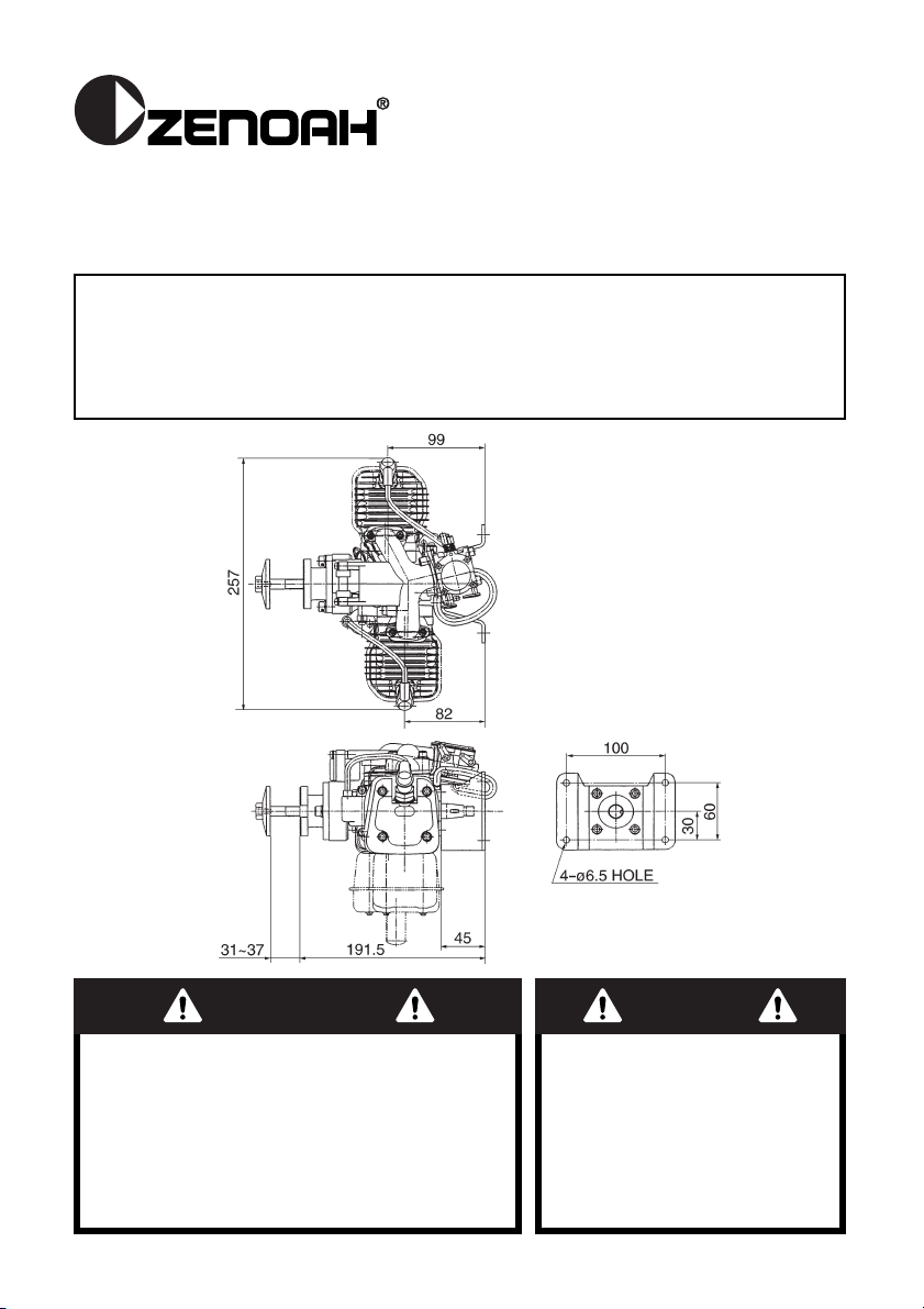
Make sure that the engine is mounted on the aircraft grade plywood with more than 9mm of
thickness or a mount of equivalent strength and is firmly fixed with 4 bolts.
[ NOTE ]
1. Be sure to set flat washers or metal plate on the reverse side of the mount to prevent
bolts from sinking into the mount. Before flying the aircraft, be sure to check for loose
bolts.
2. Since this engine is equipped with a float-less carburetor with a diaphragm pump, the
position of fuel tank can be freely selected.
1. Recommended propeller size.
The recommended propeller sizes are as shown in the table bellow.
This engine produces the maximum output when the engine is running at about
10,000rpm. Be sure to use a propeller which produces approximately 7,000 ~ 10,000rpm
while the aircraft is flying. When using a propeller of small diameter, a light weight
propeller is not suitable.
2. There are two types of propeller mounting bolts; L=45 and L=50. Select the proper type
of bolt depending on the thickness of propeller used and the use of the spinner.
[ NOTE ]
1. When mounting a thin propeller, cut off the end of bolt or add a flat washer.
2. When mounting the spinner, set a pin on the hub with more than 3 mm of diameter, thus
preventing slipping.
3. Propeller bolt tightening torque: 250~300kg-cm
Mix gasoline and high grade 2-stroke oil at a mixing ratio of 25 ~ 40 :1.
4. Fuel
3. Propeller
2. Mounting
1. Safety Precautions
2
Diameter x Pitch (in.)
26 x 8~10, 24 x 10~12, 22 x 12~14
Page 3
[ NOTE ]
1. Be sure to use a gasoline-resistant fuel piping. (Do not use any silicon rubber tube).
2. Never use any alcohol fuel or alcohol added fuel, or the rubber part in the carburetor will
be damaged.
1. Avoid starting engine by hand flipping propeller as it may cause injury. Make sure to start
by using built-in spring starter or large size electric starter with reduction gear (available
on the market) .
2. Make sure to put on thick glove when starting engine.
How to Start the Engine
1. Fill the fuel tank with the fuel.
2. Close the choke valve and open the throttle valve approximately 1/3 ~ 1/2 of the full open
position.
3. Rotate the propeller counterclockwise until the piston passes over its top dead point.
Then rotate it clockwise for 1/2 ~ 3/4 revolution to wind up the spring, and release the
propeller. Repeat this several times until the initial firing sound is heard.
4. Upon hearing the initial firing open the choke valve and set the throttle to the idle or
slightly open position. Take the same procedure as mentioned above step 3, and the
engine will start.
[ NOTE ]
• Be sure to keep holding propeller firmly by other hand while winding up the spring for
starter.
• Be sure to open the choke when the engine first fires.
• When the choke is opened, be sure to close the throttle valve to a position near the idle
position before starting the engine (If the engine is started while the throttle wide open it will
develop a high level of power and thrust which can be very dangerous).
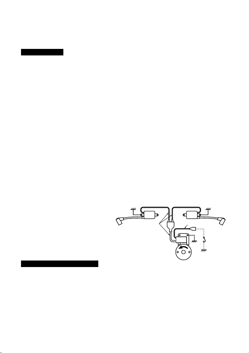
How to Stop the Engine
For stopping the engine, the black lead
wire from the coil should be grounded to
the engine body, or the throttle valve
should be closed completely.
The carburetor is provided with 3 adjust screws which are set to the best (approximately)
positions by our company, but they may need a little adjustment depending on the
temperature, atmospheric pressure (altitude), etc. of the area where the engine is used. Start
the engine without making any adjustments. Make readjustments only when the engine
shows any mal-functioning.
[ NOTE ]
Be sure to stop the engine before starting the adjustment, thus ensuring safety.
Idle Screw: Turning this screw clockwise increases the idling R.P.M. Turning it
6. Carburetor Adjustment
5. Operation
3
KILL
SWITCH
BLACK LEAD
RED LEAD
ENGINE BODY
EARTH
Page 4

4
counterclockwise decreases the idling R.P.M
Low Speed Needle: This is the fuel adjust screw (not the air screw). Turning this needle
clockwise makes the mixture gas leaner and turning it counterclockwise
makes it richer.
High Speed Needle: Turning this needle clockwise makes the mixture gas leaner and
turning it counterclockwise richer. Set this needle at a position which is 1/8 ~
1/4 open from the maximum R.P.M. position while the airplane is on ground.
[ NOTE ]
1. Do not tighten the High and Low Speed needles too firmly.
2. Ensure the engine is fully warmed up before use. When the engine has just started and is
not fully warmed up there may be insufficient acceleration from low speed operation and
the engine may stop.
No specific break-in is required. The engine is gradually breaking in as it is used and the
output will increase also increased gradually.
This engine is used for power source for radio controlled airplane so you are strictly
requested to check engine and relative parts of airplane.
1) Daily check (before starting)
• Leakage, damage, crack
• Muffler fixing bolts (torque, crack)
• Propeller hub (transformation, fixing bolts/nut)
(P/N:2629-51410 or 2629-91510, 3544-11510 and 1100-43231)
• Rotor (transformation, play, airgap)
2) Every 25 hours check
• Spark plug (gap, cleaning)
• Cylinder (abrasion)
• Piston/Ring (abrasion)
• Bearing (Gritty)
According to the checks, replace any part if necessary.
The engine can be disassembled or reassembled without any specific difficulties, but be
careful of the following matters;
a. For disassembling, the special tools shown in the parts list are required in addition to the
general tools. Be sure to use a new gasket when the crankcase and cylinder have been
disassembled and reassembled.
b. Disassembling rotor
1. Disassemble the spring starter.
9. Servicing
8. Maintenance
7. Engine Break-in
Low Speed
Needle
High Speed
Needle
Idle Screw
H: 11/4 ±1/4
L : 11/8 ±1/4
Standard setting
Page 5

5
2. Put the stopper (P/N.2670-96220) into a sparkplug hole (Fig.1) of the cylinder(✽) which
is located closer to the rotor than other cylinder when viewed from intake manifold side
(Fig.2).
3. Turn the rotor counterclockwise until piston touches the stopper.
4. Unscrew the rotor nut.
5. Remove the rotor by using the puller (P/N. 1490-96101).
Do not hit the crankshaft end by metal hammer, that may cause the crankshaft to be
bent out of alignment.
c. Assembling crankcase
1. Apply grease on the oil seal lips and oil on the bearing.
2. Assemble the crankshaft with a new gasket.
3. When both front and rear crankcases are tightened, the portion of gasket protruding on
the cylinder mount surface should be cut off with a knife until the gasket becomes flush
with the cylinder mounted surface.
d. Assembling piston
Before assembling the piston, apply the oil on the small end bearing and piston, and set
the piston ensuring that the arrow mark on the top of piston is directed toward the
direction of exhaust port.
e. Re-assembling cylinder and intake manifold
1. Coat the oil on the inner surface of cylinder.
2. The piston is provided with a knock pin which stops the piston ring from turning. Set the
split section of piston ring at the knock pin and assemble the cylinder ensuring not to
break the piston ring.
3. Keep cylinder bolts unfastened before installing the intake manifold to the cylinder.
4. Fixing the intake manifold to the intake port of each cylinder.
5. Then, tighten cylinder bolts.
f. Assembling rotor
Make sure to put lock tight (Medium strength type: TreeBond 1322N, LOCTITE 242,243,
PACER ZAP Z-42) on the rotor fixing nut (P/N:1100-43231).
g. Recommended tightening torque for bolts/nuts
Be sure to follow the recommended tightening torque for bolts/nuts in assembling at each
part.
1. Rotor nut (M10) : 250 ~ 300 kg-cm
2. Crankcase bolt (M5) : 50 ~ 90 kg-cm
3. Cylinder bolt (M5) : 50 ~ 90 kg-cm
4. Engine mount bolt (M6) : 80 ~ 120 kg-cm
5. Propeller hub bolt (M6) : 80 ~ 120 kg-cm
6. Source coil bolt (M4) : 15 ~ 20 kg-cm
h. Adjusting air gap of coil.
The air gap of coil should be adjusted to 0.3 mm (0.01").
i. Adjusting ignition time.
This engine with the point-less C.D.I. type requires no adjustments of ignition time.
Fig. 1
Fig. 2
(✽)
Stopper
Page 6

6
10. Specifications
11. Parts List
G800BPU, G800BPU-1
Model ..............................................G800BPU · G800BPU-1
Type ................................................
Air cooled two stroke cycle opposed cylinder type gasoline engine
Displacement ..................................79.9cc (4.88cu. in)
Bore x Stroke x Number of cylinder
.......40.5mm x 31mm x 2 (1.60 in x 1.22 in x 2 )
Compression ratio ...........................8.1 : 1
Maximum output ..............................5.52kW/10000rpm [4.41kW/10000rpm with Muffler]
Operating engine speed ..................1800 ~ 10000rpm
Weight .............................................3.5kg (7.9Ibs) with mufflers & spring starter
Ignition system ................................CDI type flywheel magneto
Carburetor .......................................WALBRO WJ-64
Fuel .................................................Gasoline oil mixture 25 ~ 40 : 1
Spark plug .......................................CHAMPION RCJ-7Y
Recommended propeller sizes (inch)
....26 x 8 ~ 10, 24 x 10 ~ 12, 22 x 12 ~ 14
Specifications are subject to change without notice.
Page 7

7
1 T2080-12110 Cylinder 2
2 T2080-14110 Manifold 1
3 2850-14123 Gasket, inlet 2
4 3310-72150 Bolt 4
5 2898-81000 Carburetor assy, WJ-64 1
6 3304-81441 • Ring 1
7 1148-81390 • Ring 1
8 2898-81120 • Cover 1
9 2898-81130 • Cover 1
10 2898-81150 • Shaft 1
11 2898-81340 • Valve 1
12 2898-81170 • Shaft 1
13 2898-81440 • Lever 1
14 2898-81180 • Valve 1
15 3310-81311 • Valve 1
16 2898-81450 • Plug 1
17 3360-81440 • Plug 1
18 2898-81220 • Ball 1
19 2898-81240 • Gasket 1
20 2898-81230 • Gasket 1
21 2898-81260 • Diaphragm 1
22 2898-81270 • Diaphragm 1
23 3310-81240 • Screw 1
24 2898-81330 • Screw 1
25 2898-81140 • Screw 4
26 1492-81560 • Screw 1
27 3310-81351 • Screw 4
28 2898-81370 • Spring 1
29 2898-81350 • Spring 1
30 1491-81160 • Spring 2
31 2898-81390 • Spring 1
32 2898-81420 • Needle 1
33 2898-81410 • Needle 1
34 1282-81560 • Screen 1
35 3306-81380 • Screen 1
36 7620-81610 • Pin 1
37 2898-81250 • Lever 1
38 2880-81470 • Screw 2
39 3356-81430 • Plug 1
40 2898-14131 Gasket, carburetor 1
41 01252-30550 Bolt 2
42 2898-14210 Gasket, cylinder 2
43 01252-30520 Bolt 8
44 2898-21001 Crankcase assy (No.45~51) 1
45 2629-21130 • Pin 4
46 06030-06202 • Bearing 2
47 04065-03515 • Snap ring 2
48 06034-06202 • Bearing 1
49 1400-21220 • Oil seal 1
Q' ty
/unit
DescriptionParts No.
Index
No.
50 2670-21250 • Elbow 1
51 1065-81100 • Pipe 1
52 2898-21310 Gasket, crankcase 1
53 01252-30520 Bolt 4
54 T2002-41110 Piston 2
55 8488C41200 Ring, piston 4
56 2850-41310 Pin, piston 2
57 1300-41320 Snap ring 4
58 2850-41410 Bearing 2
59 2850-41510 Thrust washer 4
60 2898-42000 Crankshaft comp 1
61 1300-42410 Shim 0~2
62 1000-43240 Key 1
63 1100-43231 Nut 1
64 01641-21016 Washer 1
65 0290-21025 Washer 1
66 1490-71110 Rotor 1
67 2629-71210 Source coil 1
68 2629-71311 Ignition coil 2
69 2898-71510 Cord 1
70 2850-72110 Cap, plug 2
71 1400-72121 Spring 2
72 1630-73110 Spark plug 2
73 0263-30414 Screw 4
74 0260-30422 Screw 2
75 2898-15110 Muffler 2
76 T2100-15210 Gasket, muffler 2
77 3356-15220 Bolt 4
78 2850-15230 Nut 4
79 2898-74110 Mount 1
80 01252-30614 Bolt 3
81 3310-71150 Washer 4
❈82 2699-75110 Boss 1
❈83 2699-75200 Clutch comp 1
❈84 2699-75310 Spring 1
❈85 2699-75320 Collar 1
❈86 01252-30625 Bolt 1
❈87 2699-75410 Pad 1
88 2628-51101 Hub. propeller comp 1
❈89 04025-00312 • Pin, spring 2
90 3544-11510 Bolt 2
91 2629-51310 Hub, washer 1
92 2629-51410 Bolt 1
93 2629-91510 Bolt 1
94 1110-91320 Socket 1
95 1490-96101 Puller assy (Optional) 1
96 2670-96220 Stopper (Optional) 1
Q' ty
/unit
DescriptionParts No.
Index
No.
G800BPU, G800BPU-1
❈ : Without for G800BPU-1.
Page 8

12. Warranty
WARRANTY TERMS
1) Scope of Application
This engine manufactured by Husqvarna Zenoah Co., Ltd. (herein after “Zenoah”).
And sold to the user directly or through distributor/manufacturer, shall entitle to be
covered by this warranty.
2) Limits of Warranty
Zenoah warrants that;
1. The quality disclosed in the specifications.
2. The engine which shall be considered defective by Zenoah, caused by material or
production fault.
3) Limits of Compensation
1. Zenoah compensates such quality, material and production faults by repairing or
replacing through distributor/manufacture.
2. Zenoah shall not compensate any other accompanied or benefit losses caused to
user and distributor/manufacture by such faults and through repairing or
replacing.
4) Term of Warranty
Three (3) months after purchased by end- user subject to 12 months from produced
month.
5) Exempt from Warranty
Zenoah shall not warrant this engine even if the fault has been caused during the
period of terms of Warranty, in case that.
1. Any faults, failures caused from neglect of proper operation and maintenance
described in OWNER’S MANUAL.
2. Any modification not approved by Zenoah.
3. Normal abrasion and deterioration.
4. Consuming parts.
5. Using any parts which have not been certified by Zenoah.
6. Add-on or modified use.
1-9 Minamidai, Kawagoe-city, Saitama, 350-1165 Japan
Phone: (+81)49-243-6917 Fax: (+81)49-243-7197
 Loading...