

Page 1
The engine exhaust from this product
contains chemicals known to the State
of California to cause cancer, birth
defects or other reproductive harm.
WARNING
OWNER/OPERATOR MANUAL
CHAINSAWS
2812-93112 (901)
G455AVS
IMPORTANT:
Before operating your RedMax product,
read this manual carefully and completely.
Page 2

Page 3

Thank you for choosing our RedMax® chain saw.
This manual will provide you with full understanding of the necessary
instructions for assembly, operation and maintenance of the
equipment.
Please read it carefully before starting operation.
For continued safe and reliable operation, use ONLY original
RedMax parts and accessories, Adhere to all notes and warnings.
CONTENTS
1. For Safe Operation································································· 2
2. Installing Guide Bar and Saw Chain ···································· 4
3. Fuel and Chain Oil ································································· 5
4. Operating Engine··································································· 6
5. Sawing ·················································································· 10
6. Maintenance ········································································· 12
7. Maintenance of Saw Chain and Guide Bar························ 14
8. Troubleshooting Guide························································ 17
9. Specifications······································································· 18
10. Parts List··············································································· 19
Page 4

1. For Safe Operation
2
1. Never operate a chain saw when you are
fatigued, ill, or upset, or under the
influence of medication that may make
you drowsy, or if you are under the
influence of alcohol or drugs.
2. Use safety footwear, snug fitting clothing
and eye, hearing and head protection
devices.
3. Always use caution when handling fuel.
Wipe up all spills and then move the
chain saw at least ten(10) feet(three(3)
m) from the fueling point before starting
the engine.
3a) Eliminate all sources of sparks or
flame (ie. smoking, open flames, or
work that can cause sparks) in the
areas where fuel is mixed, poured, or
stored.
3b)Do not smoke while handling fuel or
while operating the chain saw.
4. Do not allow other persons to be near
the chain saw when starting the engine
or cutting a wood. Keep bystanders and
animals out of the work area. Children,
pets, and bystanders should be a
minimum of thirty(30) feet away when
you start or operate the chain saw.
5. Never start cutting until you have a clear
work area, secure footing, and planned
retreat path from the falling tree.
6. Always hold the chain saw firmly with
both hands when the engine is running.
Use a firm grip with thumb and fingers
encircling the chain saw handles.
7. Keep all parts of your body away from
the saw chain when the engine is
running.
8. Before you start the engine, make sure
the saw chain is not contacting anything.
9. Always carry the chain saw with the
engine stopped, the guide bar and saw
chain to the rear, and the muffler away
from your body.
10. Always inspect the chain saw before
each use for worn, Ioose, or changed
parts. Never operate a chain saw that is
damaged, improperly adjusted, or is not
completely and securely assembled. Be
sure that the saw chain stops moving
when the throttle control trigger is
released.
11. All chain saw service, other than the
items listed in the Operator’s Manual,
should be performed by competent chain
saw service personnel. (e.g., if improper
tools are used to remove the flywheel, or
if an improper tool is used to hold the
flywheel in order to remove the clutch,
structural damage to the flywheel could
occur which could subsequently cause
the flywheel to disintegrate).
12. Always shut off the engine before setting
it down.
13. Use extreme caution when cutting small
size brush and saplings because slender
material may catch the saw chain and be
whipped toward you or pull you off
balance.
14. When cutting a limb that is under
tension, be alert for spring back so that
you will not be struck when the tension in
the wood fibers is released.
15. Keep the handles dry, clean and free of
oil or fuel mixture.
Page 5

3
16. Operate the chain saw only in well
ventilated areas. Never start or run the
engine inside a closed room or building.
Exhaust fumes contain dangerous
carbon monoxide.
17. Do not operate a chain saw in a tree
unless specially trained to do so.
18. Guard against kickback. Kickback is the
upward motion of the guide bar which
occurs when the saw chain at the nose
of the guide bar contacts an object.
Kickback can lead to dangerous loss of
control of the chain saw.
19. When transporting your chain saw, make
sure the appropriate guide bar scabbard
is in place.
20. This chain saw is equipped with a spark
arrester built-in muffler. Periodically
check the arrester to keep it in good
order.
KICKBACK SAFETY PRECAUTIONS FOR
CHAIN SAW USERS
– WARNING –
● Kickback may occur when the nose or tip of the guide bar touches an object, or when the
wood closes in and pinches the saw chain in the cut. Tip contact in some cases may
cause a lightning fast reverse reaction, kicking the guide bar up and back towards the
operator. Pinching the saw chain along the top of the guide bar may push the guide bar
rapidly back towards the operator. Either of these reactions may cause you to lose
control of the saw which could result in serious personal injury.
● Do not rely exclusively on the safety devices built into your saw. As a chain saw user you
should take several steps to keep cutting jobs free from accident or injury.
(1) With a basic understanding of kickback you can reduce or eliminate the element of
surprise. Sudden surprise contributes to accidents.
(2) Keep a good grip on the saw with both hands, the right hand on the rear handle, and
the left hand on the front handle, when the engine is running. Use a firm grip with
thumbs and fingers encircling the chain saw handles. A firm grip will help you reduce
kickback and maintain control of the saw. Don’t let go.
(3) Make certain that the area in which you’re cutting is free from obstructions. Do not let
the nose of the guide bar contact a log, branch, or any other obstruction which could
be hit while you are operating the saw.
(4) Cut at high engine speeds.
(5) Do not overreach or cut above shoulder height.
(6) Follow manufacturers sharpening and maintenance instructions for saw chain.
(7) Only use replacement bars and chains specified by the manufacturer or the
equivalent.
Page 6
The saw chain has very sharp edges. Use
thick protective gloves for safety.
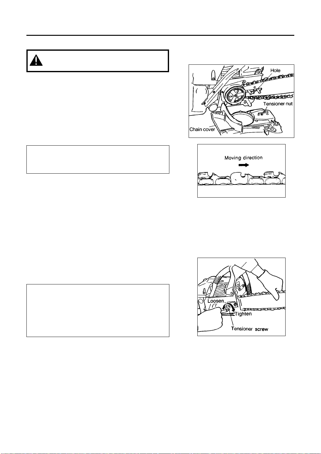
1. Loosen the nuts and remove the chain cover.
2. Install the attached spike to the power unit.
3. Gear the chain to the sprocket and, while fitting
the saw chain around the guide bar, mount the
guide bar to the power unit, Then adjust the
position of chain tensioner nut on the chain
cover to the lower hole of guide bar.
Note:
Pay attention to the correct direction of the saw
chain.
4. Fit the chain cover to the power unit and fasten
the nuts to finger tightness.
5. While holding up the tip of the bar, adjust the
chain tension by turning the tensioner screw until
the tie straps just touch the bottom side of the
bar rail.
6. Tighten the nuts securely with the bar tip held
up. Then check the chain for smooth rotation
and proper tension while moving it by hand. If
necessary, readjust with the chain cover loose.
7. Tighten the tensioner screw.
Note :
A new chain will expand its length in the
beginning of use. Check and readjust the
tension frequently as a loose chain can easily
derail or cause rapid wear of itself and the guide
bar.
2. Installing Guide Bar and Saw Chain
4
Page 7
■ FUEL
The RedMax engines are lubricated by oil
specially formulated for air-cooled 2-cycle
gasoline engine use. If RedMax oil is not
available, use an anti-oxidant added quality
oil expressly labeled for air-cooled 2-cycle
engine use.
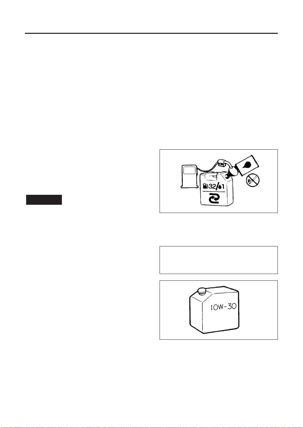
RECOMMENDED MIXING RATIO
GASOLINE 32 : OIL 1
Exhaust emission are controlled by the
fundamental engine parameters and
components (eq., carburation, ignition
timing and port timing) without addition
of any major hardware or the introduction
of an inert material during combustion.
These engines are certified to operate on
un-leaded gasoline.
The fuel is highly flammable. Do not
smoke or bring any flame or sparks near
fuel.
• HOW TO MIX FUEL
1. Measure out the quantities of gasoline
and oil to be mixed.
2. Put some of the gasoline into a clean,
approved fuel container.
3. Pour in all of the oil and agitate well.
4. Pour in the rest of gasoline and agitate
again for at least one minute.
5. Put a clear indication on the outside of the
container to avoid mixing up with gasoline
or other containers.
WARNING !
3. Fuel and Chain oil
FOR YOUR ENGINE LIFE, AVOID;
1. FUEL WITH NO OIL(RAW GASOLINE) –
It will cause severe damage to the engine
inner parts very quickly.
2. GASOHOL – It can cause deterioration of
rubber and/or plastic parts and disruption
of engine lubrication.
3. OIL FOR 4-CYCLE ENGINE USE or
WATER COOLED 2-CYCLE ENGINE
USE – It can cause spark plug fouling,
exhaust port blocking, or piston ring
sticking.
■ CHAIN OIL
Use motor oil SAE 10W-30 all year round, or
SAE 30-40 in summer and SAE 20 in winter.
NOTE:
Do not use waste or regenerated oil that
can cause damage to the oil pump.
5
Page 8
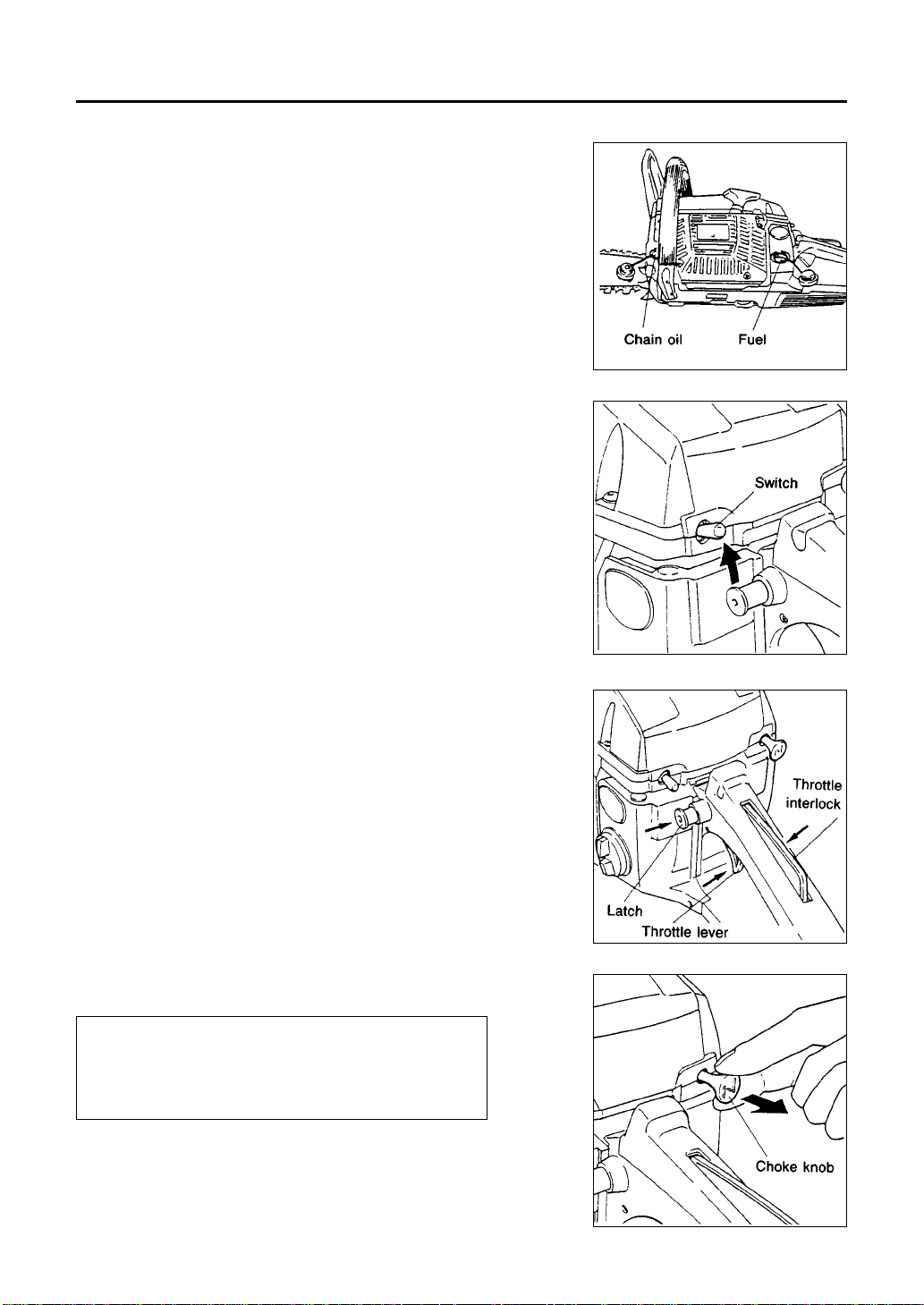
Starting engine
1. Fill fuel and chain oil tanks respectively, and
tighten the caps securely.
2. Tilt the switch lever upward.
3. While holding the throttle lever together with the
throttle interlock, push in the side latch and
release the throttle lever to hold it at the starting
position.
4. Pull out the choke knob to the closed position.
Note:
When restarting immediately after stopping the
engine, Ieave the choke knob at the open
position.
4. Operating Engine
6
Page 9
5. While holding the saw unit securely on the
ground, pull the starter rope vigorously.
Do not start the engine while hanging the
chain saw with a hand. The saw chain may
touch your body. It's very dangerous.
6. When engine has ignited first, push in the choke
knob and pull the starter again to start the
engine.
7. Allow the engine to warm up with the throttle
lever pulled slightly.
Keep clear of the saw chain as it will start
rotating upon starting of engine.
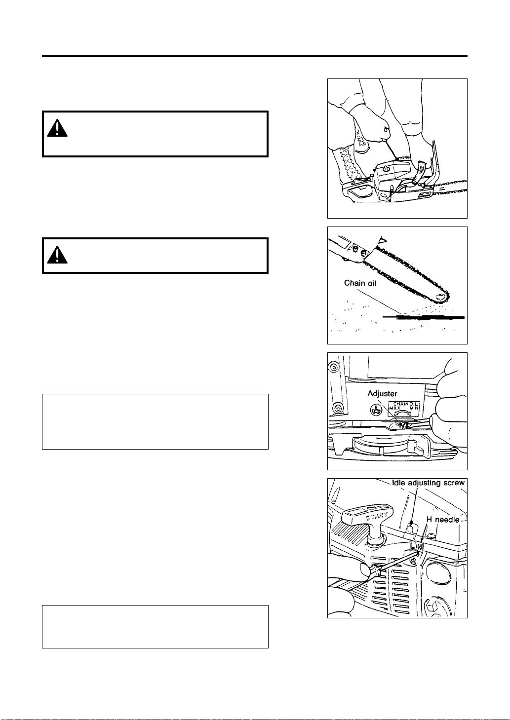
Checking oil supply
After starting the engine, run the chain at medium
speed and see if chain oil is scattered oft as shown
in the figure.
The chain oil flow can be changed by inserting a
screwdriver in the hole on bottom of the clutch
side. Adjust according to your work conditions.
Note:
The oil tank should become nearly empty by the
time fuel is used up. Be sure to refill the oil tank
every time when refueling the saw.
Adjusting carburetor
The carburetor has been adjusted at the factory.
Should your unit need readjustment due to the
changes in altitude or operating conditions, please
let your skillful dealer make the adjustment. A
wrong adjustment may cause damage to your unit.
If you have to make the adjustment yourself,
please carefully follow the procedure below.
Note :
Be sure to adjust the carburetor with the bar
chain attach ed.
7
Page 10

1. H and L needles are restricted within the number
of turn as shown below, because this engine
conforms to 1995 California regulations for utility
and lawn and garden equipment engines as
applicable.
H needle:
1
/4
L needle: fixed
2. Start engine and allow it to warm up in low
speed for a few minutes.
3. Turn idle adjusting screw (T) counterclockwise
so that saw chain does not turn. If idling speed is
too slow, turn the screw clockwise.
4. Make a test cut adjust the H needle for best
cutting power, not for maximum speed.
Icing prevention system
This system prevents icing of the carburetor which
sometimes happen while sawing in winter.
When your saw is possible to be frozen at the
carburetor during operation, use the system as
follows:
1. Loosen a screw and remove the screen on the
back of the air cleaner cover.
2. Turn the screen a half and reinstall to the cover.
Never use the system in normal
temperature because that can cause
starting failure due to overheating of the
carburetor.
When using the saw with the anti-icing setting,
frequently check the screen and keep it clean of
saw dust.
8
Page 11

Chain brake
This machine is equipped with an automatic brake
to stop saw chain rotation upon occurrence of
kickback while in saw cutting operation. The brake
is automatically operated by inertial force which
acts on the weight fitted inside the front gurd.
This brake can also be operated manually with the
front guard turned down to the guide bar.
To release brake, pull up the front guard toward the
front handle till “click” sound is heard.
[Caution]
Be sure to confirm brake operation on the daily
inspection.
How to confirm:
1) Turn off the engine.
2) Holding the chain saw horizontally, release your
hand from the front handle, hit the tip of the
guide bar to a stump or a piece of wood, and
confirm brake operation. Operating level varies
by bar size.
In case the brake is not effective, ask our dealer
inspection and repairing.
The engine, if being kept rotated at high speed with
the brake engaged, heats the clutch, causing a
trouble. When the brake is operated while in
operation, immediately release your fingers from
the throttle lever and stop the engine.
Stopping engine
1. Release the throttle lever to allow the engine
idling for a few minutes.
2. Move the switch lever downward.
9
Page 12

NOTE:
• Before proceeding to your job, read “For
Safe Operation” section. It is
recommended to first practice sawing
easy logs. This also helps you get
accustomed to your unit.
• It is not necessary to force the saw into
the cut. Apply only light pressure while
running the engine at full throttle.
• Racing the engine with the chain seized in
a cutaway can damage the clutch system.
When the saw chain is caught in the cut,
do not attempt to pull it out by force, but
use a wedge or a lever to open the cut.
■ GUARD AGAINST KICKBACK
• This saw is equipped with a special “low
kickback” chain that greatly reduces the
severty of kickback should it occur.
• The saw chain has been tested in
accordance with American National
Standard Safety Specifications for
gasoline powered chain saw (ANSI
B175.1 1985) as having an acceptable
low kickback level. On this saw never use
any chain other than those recommended
on page 12 of this manual, or which is not
designated as meeting the ANSI B175.1
kickback levels on this saw.
• Low kickback saw chains are chains
which have met the kickback
requirements of ANSI B175.1 when tested
on the representative samples of chain
saws below 3.8 C.I.D. specified in ANSI
B175.1.
• The guide bar supplied with this saw has
an under 1.2 inch radius sprocket nose
which produces a specific kickback
energy. Never use a bar with a larger
nose radius. Use only those
recommended on page 12.
• The length of bars has a great effect on
kickback. Use only those length as
specified on page 12.
• This saw is also equipped with a chain
brake that will stop the chain in the event
of kickback if operating properly. You
must check the chain brake operation
before each usage by running the saw at
full throttle for 1 or 2 seconds and pushing
the front hand guard forward. The chain
should stop immediately with the engine
at full speed. If the chain is slow to stop or
does not stop then replace the brake band
and clutch drum before use.
• It is extremely important that the chain
brake be checked for proper operation
before each use and that the chain be
sharp in order to maintain the kickback
safety level of this saw. Removal of the
safety devices, inadequate maintenance,
or incorrect replacement of the bar or
chain may increase the risk of serious
personal injury due to kickback.
■ FELLING A TREE
[CAUTION!] When you fell a tree, be sure to
warn your neighboring workers of the
danger.
5. Sawing
10
Page 13

1. Decide the felling direction considering the
wind, Iean of the tree, location of heavy
branches, ease of job after felling, and
other factors .
2. While clearing the area around the tree,
arrange a good foothold and retreat path.
3. Make a notch cut one-third of the way into
the tree on the felling side.
4. Make a felling cut from the opposite side
of the notch and at a level slightly higher
than the bottom of the notch.
■ LOGGING AND LIMBING
[CAUTION!]
1. Always ensure your foothold as well as
stability of the tree.
2. Be alert to the rolling over of a cut log.
3. Read the instructions in “For Safe
Operation” to avoid kickback of the
saw.
Before starting work, check the direction of
bending force inside the log to be cut.
Always finish cutting from the opposite side
of bending direction to prevent the guide bar
from being caught in the cutaway.
• Cutting an unpillowed log
Saw down halfway, then roll the log over and
cut from the opposite side.
• Cutting a pillowed log
In the area A in the picture right above, saw
up from the bottom one-third and finish by
sawing down from the top. In the area B,
saw down from the top one-third and finish
by sawing up from the bottom.
• Limbing a felled tree
[CAUTION!]
Be alert to the spring back of a cut limb.
First check which way the limb is bent. Then
make a shallow cut into the compressed side
to prevent the limb from being torn. Cut
through from the tensed side.
• Pruning
[CAUTION!]
1. Do not use an unstable foothold or a
stepladder.
2. Do not overreach.
3. Do not cut above shoulder height.
4. Always use both hands to grip the saw.
Cut up from the bottom, finish down from the
top.
11
Page 14

6. Maintenace
Before cleaning, inspecting or repairing
your unit, make sure that engine has
stopped and is cool. Disconnect the spark
plug to prevent accidental starting.
A.Maintenance after each use
1. Air filter
Dust on the cleaner surface can be removed by
tapping a corner of the cleaner against a hard
surface. To clean dirt in the meshes, split the
cleaner into halves and brush in gasoline. When
using compressed air, blow from the inside.
To assemble the cleaner halves, press the rim until
it clicks.
2. Oiling port
Dismount the guide bar and check the oiling port
for clogging.
3. Guide bar
When the guide bar is dismounted, remove
sawdust in the bar groove and the oiling port.
Grease the nose sprocket from the feeding port on
the tip of the bar.
4. Others
Check for fuel leakage and loose fastenings and
damage to major parts, especially handle joints
and guide bar mounting. If any defects are found,
make sure to have them repaired before operating
again.
12
Page 15

B.Periodical service points
1. Cylinder fins
Dust clogging between the cylinder fins will cause
overheating of the engine. Periodically check and
clean the cylinder fins after removing the air
cleaner and the cylinder cover. When installing the
cylinder cover, make sure that switch wires and
grommets are positioned correctly in place.
2. Fuel filter
(1) Using a wire hook, take out the filter from the
filler port.
(2) Disassemble the filter and wash with gasoline,
or replace with a new one if needed.
Note:
• After removing the filter, use a pinch to hold
the end of the suction pipe.
• When assembling the filter, take care not to
allow filter fibers or dust inside the suction
pipe.
3. Oil tank
With a wire hook, take out the oil filter through the
filler port and clean in gasoline. When putting the
filter back into the tank, make sure that it comes to
the front right corner. Also clean off dirt in the tank.
4. Spark plug
Clean the electrodes with a wire brush and reset
the gap to .025 in. as necessary.
Note:
Use a Champion RCJ-7Y or NGK BPMR7A for
replacement.
5. Sprocket
Check for cracks and for excessive wear interfering
with the chain drive. If the wearing is found
obviously, replace it with a new one. Never fit a
new chain on a worn sprocket, or a worn chain on
a new sprocket.
6. Front and Rear dampers
Replace if adhered part is peeled or crack is
observed on the rubber part.
13
Page 16

A.Saw Chain
It is very important for smooth and safe
operation to keep the cutters always sharp.
Your cutters need to be sharpened when:
• Sawdust becomes powder-like.
• You need extra force to saw in.
• The cut way does not go straight.
• Vibration increases.
• Fuel consumption increases.
Cutter setting standards:
Be sure to wear safety gloves.
Before filing:
• Make sure the saw chain is held securely.
• Make sure the engine is stopped.
• Use a round file of proper size for your
chain.
Chain type 33SL
File size 4.5mm
Place your file on the cutter and push straight
forward.
Keep the file position as illustrated.
7. Maintenace of Saw Chain and Guide Bar
14
Page 17

After every cutter has been set, check the depth
gauge and file it to the proper level as illustrated.
Be sure to round off the front edge to
reduce the chance of kickback or tie-strap
breakage.
Make sure every cutter has the same length and
edge angles as shown below.
15
Page 18

B. Guide Bar
• Reverse the bar occasionally to prevent partial
wear.
• The bar rail should always be a square. Check
for wear of the bar rail. Apply a ruler to the bar
and the outside of a cutter. If a gap is observed
between them, the rail is normal. Otherwise, the
bar rail is worn. Such a bar needs to be
corrected or replaced.
16
WARNING:
This saw is equipped with the following low kickback bar/chain combination:
RedMax® Part Number
Saw Model Bar Size Guide Bar Saw Chain
G455AVS 16” G0021 33SL-66X
For replacement use only above bars and chains or the following:
OREGON BAR
16 inch DOUBLE GUARD™ Pro bar,
Mount code #A195.
OREGON CHAIN
G455AVS
33SL
Page 19

Check fuel for water or incorrect mixture. Replace with proper fuel.
Check engine for flooding. Remove and dry the spark plug.
Repeat pulling starter with no choke.
Remove spark plug and check for correct sparking. Replace with a new plug.
8. Troubleshooting Guide
17
Case 1. Starting failure:
Check fuel for water or incorrect mixture. Replace with proper fuel.
Check air filter and fuel filter for clogging. Clean or replace as necessary.
Check carburetor for inadequate adjustment. Readjust speed needles. (See page 8.)
Case 2. Lack of power/Poor acceleration/Rough idling:
Check oil tank to see if empty. Supply oil.
Check oil passage and ports for clogging. Clean.
Case 3. Oil does not come out:
When your unit seems to need further service, please consult our service shop in your area.
Page 20

9. Specifications
Model G455AVS
Power unit:
Dis placement cc (cu. in.) 45.0 (2. 75)
Fuel Mixture (Gasoline 32: Two-cycle oil 1)
Fuel tank capacity cc (pints) 550 (1.17)
Chain oil Motor oil SAE#10W-30
Oil tank capacity cc (pints) 260 (0.55)
Carburetor Diaphragm type (Walbro WT)
Ignition system C.D.I. with timing advance function
Spark plug Champion RCJ-7Y
Oil feeding system Mechanical plunger pump with adjuster
Sprocket Teeth x Pitch 7T x .325”
Dimensions (L x W x H) mm (in.) 410 x 235 x 265 (16.1 x 9.3 x 10.4)
Dry weight : Power unit only kg (lbs) 4.85 (10.7)
Cutting head:
Guide bar – Type Sprocket nose
– Size in. 16
Saw chain – Type Oregon 33SL
– Pitch in. .325
– Gauge in. .050
18
Specifications are subject to change without notice.
Page 21

10. Parts List
NOTE :
1. Use KOMATSU ZENOAH genuine parts as specified in the parts list for repair and/or
replacement.
2. KOMATSU ZENOAH does not warrant the machines, which have been damaged by the
use of any parts other than those specified by the company.
3. When placing parts orders for repair and/or replacement, check if the model name and the
serial number are applicable to those specified in the parts list, then use parts number
described in the parts list.
4. The contents described in the parts list may change due to improvement.
5. The parts for the machine shall be supplied seven (7) years after the machine is
discontinued. [It is possible that some specific parts may be subject to change of their
delivery term and list price within the limit of ten (7) years after the machine is
discontinued. It is also possible that some parts may be available even after the limit of
seven (7) years.]
CHAINSAWS
G455AVS
19
APPLICABLE SERIAL NUMBER : 918747 and up
Page 22

10. Parts List : G455AVS
20
Page 23

21
Page 24

Key# Part Number Description Q'ty NOTE
1 2670-12112 CYLINDER 1
2 2810-14110 INLET PIPE 1
3 2817-14121 GASKET 1 ✻1
4 2670-14130 SCREW 2
5 2880-14150 GUIDE 1
6 2670-14311 BRACKET 1
7 2670-14320 SCREW 2
8 2880-14350 SPACER 1
9 2880-14360 GASKET 1
10 2670-14211 GASKET 1 ✻1
11 2850-14220 BOLT 4
12 2810-15220 BOLT 2
13 2850-15230 NUT 2
14 2812-15103 MUFFLER ASS’Y 1
15 2812-15113 MUFFLER 1
16 3357-15120 SPARK ARRESTER 1
17 2670-25430 SCREW 1
18 ––––––––– ––––– –
19 2670-14130 SCREW 1
20 3356-15210 GASKET 1 ✻1
21 2812-15310 COVER 1
22 2672-15320 SPACER 1
23 2670-14220 SCREW 1
24 2812-21000 CRANKCASE ASS’Y 1
25 2810-21240 BEARING 2
26 04065-03515 SNAP RING 1
27 2670-21210 SEAL 1
28 2670-21220 SEAL 1
29 2616-21230 STUD 2
30 2670-21250 ELBOW 1
31 2810-22511 STOPPER 1
32 2810-22521 STOPPER 1
33 2670-21311 GASKET 1 ✻1
34 2670-21320 SCREW 5
35 2810-22210 PIPE 1
36 3310-82230 CLIP 1
37 2810-22411 MAT 1
38 2670-41113 PISTON 1
39 2670-41211 RING 2
40 3350-41310 PIN 1
41 3350-41320 SNAP RING 2
42 1400-41410 BEARING 1
43 2670-41510 WASHER 2
44 2880-42001
CRANKSHAFT COMP.
1
45 1000-43240 KEY 1
46 2670-71101 ROTOR ASS’Y 1
47 1850-75220 RATCHET 2
48 2670-71130 SPRING 2
49 0308-00040 RNG 2
50 3350-43231 NUT 1
51 0290-20820 WASHER 1
52 2880-71300 COIL ASS’Y 1
53 2810-71204 COIL COMP. 1
54 2810-71220 CORD 1
Key# Part Number Description Q'ty NOTE
55 2670-71230 GROMMET 1
56 2810-72110 CAP 1
57 1400-72121 SPRING 1
58 2670-71320 TUBE 1
59 ––––––––– ––––– –
60 2810-71250 GROMMET 1
61 2670-14220 SCREW 2
62 2810-21270 PLATE 1
63 0260-30410 SCREW 2
64 2670-71510 CORD 1
65 2810-71610 SWITCH 1
66 2670-71621 COVER 1
67 2880-71630 PLATE 1
68 2670-14130 SCREW 1
69 1630-73110 SPARK PLUG 1 ✻1
Champiopn RCJ7Y
70 2880-75003 STARTER ASS’Y 1
71 2810-75110 CASE 1
72 2810-75120 GUIDE 1
72-1 2810-75150 BOSS 1
73 2670-75212 REEL 1
74 3317-75300 SPRING COMP. 1
75 2670-75411 ROPE 1
76 1400-75170 KNOB 1
77 3310-75431 WASHER 1
78 1400-86280 WASHER 1
79 2670-14220 SCREW 1
80 2880-75600 COVER COMP. 1
81 2670-14320 SCREW 4
82 2812-75130 LABEL 1
83 2881-98611
SNOW PROTECTOR
1
✻2 Optional
84 2810-32100
LEFT HANDLE COMP.
1
85 2671-32210 SCREW 4
86 2810-33007 HANDLE ASS’Y 1
87 3330-33250 STOPPER 1
88 3310-33262 SPRING 1
89 3310-33271 KNOB 1
90 2810-33280 DAMPER (A) 1
91 2670-75520 SCREW 1
92 2810-33210 GASKET 1
93 2670-33311 LEVER 1
94 3356-33321 SPRING 1
95 04025-00524 SPRING PIN 1
96 3356-31160 LABEL 1
97 3356-83351 ARM 1
98 2670-34110 COVER 1
99 2671-32210 SCREW 1
100 2810-25210 CHAIN CATCHER 1
101 2670-14320 SCREW 1
102 2880-35111 DAMPER 3
103 2670-35120 SCREW 4
104 2810-35150 CAP 3
105 2881-35110 SPRING 1
106 2881-35120 SPACER 1
10. Parts List : G455AVS
22
✻1 Component of 2810-06012 GASKET KIT (Optional)
Page 25

Key# Part Number Description Q'ty NOTE
107 2880-35211 DAMPER 2
108 3350-35170 BOLT 2
109 2880-35250 CAP 2
110 2810-31115 CYLINDER COVER 1
111 2670-14320 SCREW 5
112 3359-83340 LABEL 1
113 2810-83305
CLEANER COVER COMP.
1
114 3356-83322 KNOB 1
115 3388-83340 GASKET 1
116 2810-83500 CLEANER COMP. 1
117 2810-83520 SEAL 1
118 1600-33130 SCREW 1
119 2810-83410 GROMMET 1
120 2810-83101 CLEANER COMP. 1
121 2813-31210 LABEL 1
122 2812-81000
CARBURETOR ASS’Y
1
123 2880-82310 GUIDE (I) 1
124 2880-82350 GUIDE (HL) 1
125 2880-82102 MANIFOLD COMP. 1
126 2810-82141 SUPPORTER 1
127 2880-82210 SCREW 2
128 2880-82410 CHOKE ROD 1
129 2670-82421 GROMMET 1
130 2670-82430 GUIDE 1
131 2880-82511 THROTTLE ROD 1
132 2810-82520 GROMMET 1
133 2810-34303 FUEL PIPE ASS’Y 1
134 2810-34312 PIPE 1
135 2810-34350 COLLAR 1
136 3302-85400 FILTER ASS’Y 1
137 3302-85420 SCREEN 2
138 3306-85450 FILTER 2
139 2670-34401 TANK CAP ASS'Y 1
140 2670-34430 GASKET 1
141 2670-34500 BREATHER ASS’Y 1
142 2670-34510 BREATHER 1
143 3350-34540 PIPE 1
144 1260-85460 CLIP 1
145 2811-98501 CLEANER COMP. 1
✻3 Optional
146 2630-31801 CAP ASS’Y 1
147 2630-31820 GASKET 1
148 2812-23100 OIL PIPE ASS’Y 1
149 2812-23120 PIPE 1
150 2812-23130 FILTER 1
151 1260-85460 CLIP 1
152 2670-23210 PIPE 1
153 3330-23121 VALVE 1
154 3350-26220 SEAL 1
155 3350-26230 CLIP 1
156 2880-55100 OIL PUMP ASS’Y 1
157 2670-55120 GEAR 1
158 2670-55220 SEAL 1
159 2670-55410 SCREW 2
160 2670-55610 COVER 1
Key# Part Number Description Q'ty NOTE
161 2670-55410 SCREW 3
162 2670-51200 CLUTCH ASS’Y 1
163 2670-51210 PLATE 1
164 3317-51231 SPRING 1
165 2810-51310 BEARING 1
166 2880-51110 DRUM 1
167 3350-51121 RIM 1
168 2670-25310 SPIKE 1
169 2670-14320 SCREW 2
170 2810-25421 PLATE 1
171 ––––––––– –––––– –
172 2670-25430 SCREW 1
173 2670-25410 GUIDE 1
174 3350-53410 NUT 2
175 2812-54004
CHAIN COVER ASS’Y
1
176 2671-53114 COVER 1
177 2880-53150 STOPPER 1
178 2671-53210 SCREW 1
179 2810-53221 NUT 1
180 2671-53230 GEAR 1
181 2671-53240 PLATE 1
182 2670-25410 GUIDE 1
183 2670-54630 SCREW 2
184 2671-53311 PROTECTOR 1
185 2812-54101 GUARD COMP. 1
186 2812-54111 GUARD 1
187 2670-54121 PIN 1
188 0308-00030 RING 1
189 2880-54130 WEIGHT 1
190 2880-54140 SPRING 1
191 2880-54150 PIN 1
192 2670-54210 SPRING 1
193 2670-54220 PIN 1
194 2670-54231 SPACER 1
195 3238-15230 WASHER 1
196 0308-00040 RING 2
197 2810-54240 PLATE 1
198 2810-54260 SPACER 1
199 2670-54302
BRAKE LEVER COMP.
1
200 2670-54410 ARM 1
201 2670-54510 BAND 1
202 3356-24140 ROLLER 1
203 2670-54610 SPRING 1
204 2880-54650 SPRING 1
205 2670-54621 COVER 1
206 2670-54630 SCREW 3
207 2672-53120 LABEL 1
208 2672-54250 GASKET 1
209 2812-31320 LABEL 1
210 2812-31410 LABEL 1
23
Page 26

10. Parts List : G455AVS
24
Page 27

25
✻1 Special tools (Opt. Part)
Key# Part Number Description Q'ty NOTE
1 2812-81000
CARBURETOR ASS’Y
–
2 3306-81380 SCREEN 1
3 2810-81120 COVER 1
4 3310-81130 SCREW 1
5 –––––––––
–––––––
–
6 2812-06020 GASKET KIT 1
7 –––––––––
–––––––
–
8 ––––––––– –––––– –
g 3310-81230 LEVER 1
10 3310-81240 SCREW 1
11 2841-81270 SPRING 1
12 3310-81250 PIN 1
13 3310-81280 COVER 1
14 3356-81310 INLET VALVE 1
15 3310-81360 SCREW 1
16 3356-81340 THROTTLE VALVE 1
17 2670-81410 SPRING 1
18 2812-81420 THROTTLE SHAFT 1
19 2630-81460 SPRING 1
20 2670-81430 SCREW 1
21 2880-81470 SCREW 2
22 –––––––––
–––––––
–
23 3310-81351 SCREW 4
24 2880-81460 CHOKE SHAFT 1
25 1148-81390 RING 1
26 3350-81350 SPRING 1
27 3350-81220 BALL 1
28 2670-81450 CHOKE VALVE 1
29 2810-81440 LEVER 1
30 2812-81510 PISTON 1
31 2812-81520 BALL 1
32 2810-81530 SPRING 1
33 G0021 BAR 16 1
34 33SL-66X CHAIN 33SL-66E 1
35 3359-97110 PROTECTOR 1
36 –––––––––
–––––––
–
37 3320-91140 WRENCH 1
38 2670-91150 SCREWDRIVER 1
39 2812-93112 OWNER’S MANUAL 1
40 2670-96002 TOOL SET 1 ✻1
41 2890-96100 PULLER ASS’Y 1 ✻1
42 2670-96210 WRENCH 1 ✻1
43 2670-96220 STOPPER 1 ✻1
44 3350-96230 GUIDE 1 ✻1
45 2670-96240 WRENCH 3 ✻1
46 2670-96310 WRENCH 1 ✻1
47 2670-96320 WRENCH 1 ✻1
48 2670-96510 GUIDE 1 ✻1
49 3350-96620 GUIDE 1 ✻1
50 2670-96660 HOLDER 1 ✻1
51 3350-96240 GAUGE 1 ✻1
52 2670-96410 WRENCH 1 ✻1
53 2810-96710 GUIDE 1 ✻1
Key# Part Number Description Q'ty NOTE
Page 28

THE CALIFORNIA AIR RESOURCES BOARD AND KOMATSU ZENOAH Co. ARE PLEASED TO
EXPLAIN THE EMISSION CONTROL SYSTEM WARRANTY ON YOUR 1995 AND LATER LAWN AND
GARDEN EQUIPMENT ENGINE. IN CALIFORNIA, NEW UTILITY AND LAWN AND GARDEN
EQUIPMENT ENGINES MUST BE DESIGNED, BUILT AND EQUIPPED TO MEET THE STATE'S
STRINGENT ANTI-SMOG STANDARDS.
KOMATSU ZENOAH Co, MUST WARRANT THE EMISSION CONTROL SYSTEM ON YOUR LAWN AND
GARDEN EQUIPMENT ENGINE FOR THE PERIODS OF TIME LISTED BELOW PROVIDED THERE HAS
BEEN NO ABUSE, NEGLECT OR IMPROPER MAINTENANCE OF YOUR LAWN AND GARDEN
EQUIPMENT ENGINE.
YOUR EMISSION CONTROL SYSTEM. MAY INCLUDE PARTS SUCH AS THE CARBURETOR, THE
IGNITION SYSTEM, AND CATALYTIC CONVERTER. ALSO INCLUDED MAY BE THE HOSES, BELTS,
CONNECTORS AND OTHER EMISSION-RELATED ASSEMBLIES.
WHERE A WARRANTABLE CONDITION EXISTS, KOMATSU ZENOAH Co. WILL REPAIR YOUR LAWN
AND GARDEN EQUIPMENT ENGINE AT NO COST TO YOU INCLUDING DIAGNOSIS, PARTS AND
LABOR.
MANUFACTURER'S WARRANTY COVERAGE:
THE 1995 AND LATER UTILITY AND LAWN AND GARDEN EQUIPMENT ENGINES ARE
WARRANTED FOR TWO YEARS. IF ANY EMISSION-RELATED PART ON YOUR ENGINE IS
DEFECTIVE, THE PART WILL BE REPAIRED OR REPLACED BY KOMATSU ZENOAH Co.
OWNER'S WARRANTY RESPONSIBILITIES:
—AS THE LAWN AND GARDEN EQUIPMENT ENGINE OWNER, YOU ARE RESPONSIBLE FOR
THE PERFORMANCE OF THE REQUIRED MAINTENANCE LISTED IN YOUR OWNER'S
MANUAL. KOMATSU ZENOAH Co. RECOMMENDS THAT YOU RETAIN ALL RECEIPTS
COVERING MAINTENANCE ON YOUR LAWN AND GARDEN ENGINE, BUT KOMATSU
ZENOAH Co. CAN NOT DENY WARRANTY SOLELY FOR THE LACK OF RECEIPTS OR FOR
YOUR FAILURE TO ENSURE THE PERFORMANCE OF ALL SCHEDULED MAINTENANCE.
—AS THE LAWN AND GARDEN EQUIPMENT ENGINE OWNER, YOU SHOULD BE AWARE,
HOWEVER, THAT KOMATSU ZENOAH Co. MAY DENY YOU WARRANTY COVERAGE IF
YOUR LAWN AND GARDEN EQUIPMENT ENGINE OR A PART HAS FAILED DUE TO ABUSE,
NEGLECT, IMPROPER MAINTENANCE OR UNAPPROVED MODIFICATION.
—YOU ARE RESPONSIBLE FOR PRESENTING YOUR LAWN AND GARDEN EQUIPMENT
ENGINE TO A KOMATSU ZENOAH Co. DISTRIBUTION CENTER AS SOON AS A PROBLEM
EXISTS. THE WARRANTY REPAIRS SHOULD BE COMPLETED IN A REASONABLE AMOUNT
OF TIME, NOT TO EXCEED 30 DAYS.
IF YOU HAVE ANY QUESTIONS REGARDING YOU WARRANTY RIGHTS AND RESPONSIBILITIES,
YOU SHOULD CONTACT KOMATSU ZENOAH AMERICA INC. AT (770)-381-5147.
CALIFORNIA EMISSION CONTROL WARRANTY STATEMENT
YOUR WARRANTY RIGHTS AND OBLIGATIONS
Page 29

RedMax CHAIN SAW
MODELS G455AVS
1-YEAR LIMITED WARRANTY
KOMATSU ZENOAH AMERICA INC.
1505 Pavilion Place Suite A
Norcross, Georgia 30093
EMISSION-RELATED PARTS, FOR TWO (2) YEARS FROM THE DATE OF ORIGINAL DELIVERY OF THE MODEL
G455AVS UNIT, KOMATSU ZENOAH AMERICA INC. (THE COMPANY), THROUGH ANY RedMax DEALER, WILL REPAIR
OR REPLACE, FREE OF CHARGE, FOR THE ORIGINAL AND EACH SUBSEQUENT PURCHASER. ANY PART OR
PARTS FOUND TO BE DEFECTIVE IN MATERIAL AND/OR WORKMANSHIP. EMISSION-RELATED PARTS ARE:
THE CARBURETOR ASSY, COIL ASSY, ROTOR, SPARK PLUG,
AIR FILTER, FUEL FILTER, INTAKE MANIFOLD, AND THE GASKETS
ALL OTHER PARTS EXCEPT ABOVE PARTS, FOR ONE (1) YEAR OF HOME USE [ NINETY (90) DAYS FOR ANY
OTHER USE ] FROM THE DATE OF ORIGINAL ANY DELIVERY OF THE MODEL G455AVS UNIT.
THE COMPANY, THROUGH ANY RedMax DEALER, WILL REPAIR OR REPLACE, FREE OF CHARGE, FOR THE
ORIGINAL PUSHCHASER, ANY PART OR PARTS FOUND TO BE DEFECTIVE IN MATERIAL AND/OR WORKMANSHIP.
THIS IS THE EXCLUSIVE REMEDY.
THE PURCHASER SHALL BEAR COSTS OF TRANSPORTING THE UNIT TO AND FROM THE RedMax DEALER.
THE PURCHASER SHALL NOT BE CHARGED FOR DIAGNOSTIC LABOR WHICH LEADS TO THE DETERMINATION
THAT A WARRANTED PART IS DEFECTIVE, IF THE DIAGNOSTIC WORK IS PERFORMED AT THE RedMax DEALER.
THE PURCHASER OR OWNER IS RESPONSIBLE FOR THE PERFORMANCE OF THE REQUIRED MAINTENANCE AS
DEFINED BY THE MANUFACTURER IN THE OWNER/OPERATOR MANUAL.
ANY WARRANTED PART WHICH IS NOT SCHEDULED FOR REPLACEMENT AS REQUIRED MAINTENANCE, OR
WHICH IS SCHEDULED ONLY FOR REGULAR INSPECTION TO THE EFFECT OF "REPAIR OR REPLACE AS
NECESSARY" SHALL BE WARRANTED FOR THE WARRANTY PERIOD. ANY WARRANTED PART WHICH IS
SCHEDULED FOR REPLACEMENT AS REQUIRED MAINTENANCE SHALL BE WARRANTED FOR THE PERIOD OF
TIME UP TO THE FIRST SCHEDULED REPLACEMENT POINT FOR THAT PART.
ANY REPLACEMENT PART THAT IS EQUIVALENT IN PERFORMANCE AND DURABILITY MAY BE USED IN NONWARRANTY MAINTENANCE OR REPAIRS, AND SHALL NOT REDUCE THE WARRANTY OBLIGATION OF THE
COMPANY.
THE COMPANY IS LIABLE FOR DAMAGES TO OTHER ENGINE COMPONENTS CAUSED BY THE FAILURE OF A
WARRANTED PARTS STILL UNDER WARRANTY.
THIS WARRANTY DOES NOT APPLY TO THOSE UNITS WHICH HAVE BEEN DAMAGED BY NEGLIGENCE OF
INSTRUCTION LISTED IN THE OWNER/OPERATOR MANUAL FOR PROPER USE AND MAINTENANCE OF THE UNITS,
ACCIDENT MISHANDLING, ALTERATION, ABUSE, IMPROPER LUBRICATION. USE OF ANY PARTS OR ACCESSORIES
OTHER THAN THOSE SPECIFIED BY THE COMPANY, OR OTHER CAUSES BEYOND THE COMPANY'S CONTROL.
THIS WARRANTY DOES NOT COVER THOSE PARTS REPLACED BY NORMAL WEAR OR HARMLESS CHANGES IN
THEIR APPEARANCE.
THERE ARE NO OTHER EXPRESS WARRANTIES.
IMPLIED WARRANTIES INCLUDING THOSE OF MERCHANTABILITY AND FITNESS FOR A PARTICULAR PURPOSE
ARE LIMITED TO ONE (1) YEAR OF HOME USE [NINETY (90) DAYS FOR ANY OTHER USE] FROM THE ORIGINAL
DELIVERY DATE.
LIABILITIES FOR INCIDENTAL OR CONSEQUENTIAL DAMAGE UNDER ANY AND ALL WARRANTIES
ARE EXCLUDED.
SOME STATES DO NOT ALLOW LIMITATION ON HOW LONG AN IMPLIED WARRANTY LASTS OR EXCLUSION OR
LIMITATION OF INCIDENTAL OR CONSEQUENTIAL DAMAGES, SO THE ABOVE LIMITATION OR EXCLUSION MAY
NOT APPLY TO YOU.
THIS WARRANTY GIVES YOU SPECIFIC LEGAL RIGHTS, AND YOU MAY ALSO HAVE OTHER RIGHTS WHICH VARY
FROM STATE TO STATE.
IF YOU NEED TO OBTAIN INFORMATION ABOUT THE NEAREST SERVICE CENTER, PLEASE CALL KOMATSU
ZENOAH AMERICA INC. AT (770)-381-5147.
IMPORTANT: YOU WILL RECEIVE A WARRANTY REGISTRATION CARD AT TIME OF PURCHASE. PLEASE FILL
OUT THE CARD AND SEND IT TO RedMax / KOMATSU ZENOAH AMERICA WITHIN SEVEN (7) DAYS. BE SURE TO
KEEP A COPY FOR YOUR RECORDS.
Page 30

KOMATSU ZENOAH AMERICA INC.
1505 Pavilion Place Suite A
Norcross, Georgia 30093
Printed in Japan
 Loading...