

Page 1

G230RC
OWNER’S SERVICE MANUAL
T2070-93110 (205)
• This engine is designed
for the radio controlled
car use. Komatsu Zenoah
assumes that no
responsibility for this
engine that is modified or
used for any other
applications.
Purchaser has all
responsibility against any
laws and regulations
existing in the country,
Komatsu Zenoah is
exempt from such law
and regulations.
• Read this OWNER’S
SERVICE MANUAL before
operating this engine.
WARNING
Page 2
Page 3
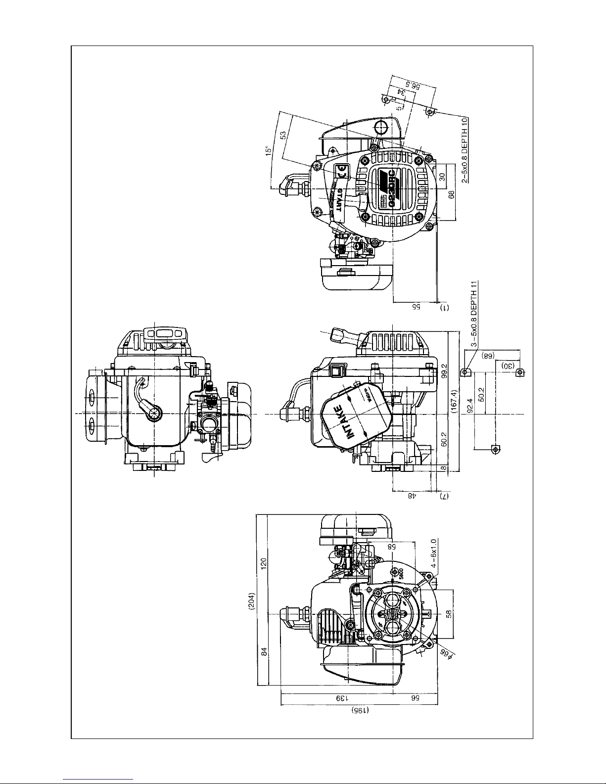
1. Specifications
2. Fuel
• Mix high-octane (over 95) gasoline and high
grade 2 cycle oil (JASO FC Grade oil or ISO
EGC grade) in the ratio of 25 : 1.
1) Never use any alcohol fuel or alcohol added
fuel, or the rubber parts in the carburetor
and engine will be damaged.
2) Gasoline is very flammable. Avoid smoking,
bringing any fires near fuel.
3) To prevent all possible problem on fueling
system, make sure to use the fuel filter and
fuel pipe packed as accessories.
WARNING
Overall Size (L x W x H) 167 x 204 x 195mm
Weight 2.07kg
Engine Type G230RC
Displacement 22.5cm
3
Clutch Engagement 6000rpm (STD Spring)
Carburetor Type WT-603
Spark Plug NGK CMR7H
Spark Plug Gap 0.65mm
Rotating Direction Counter-Clockwise (View From PTO)
3
Page 4
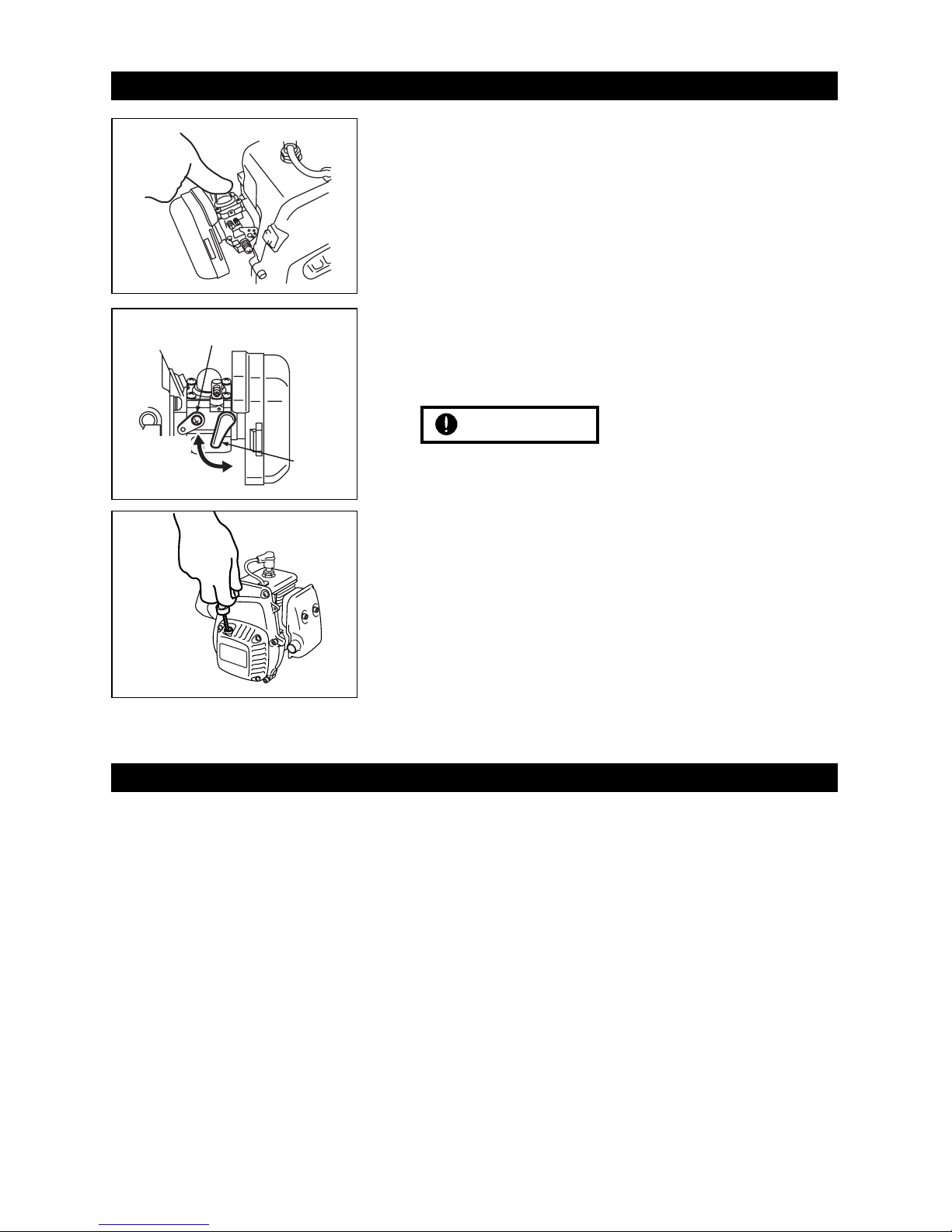
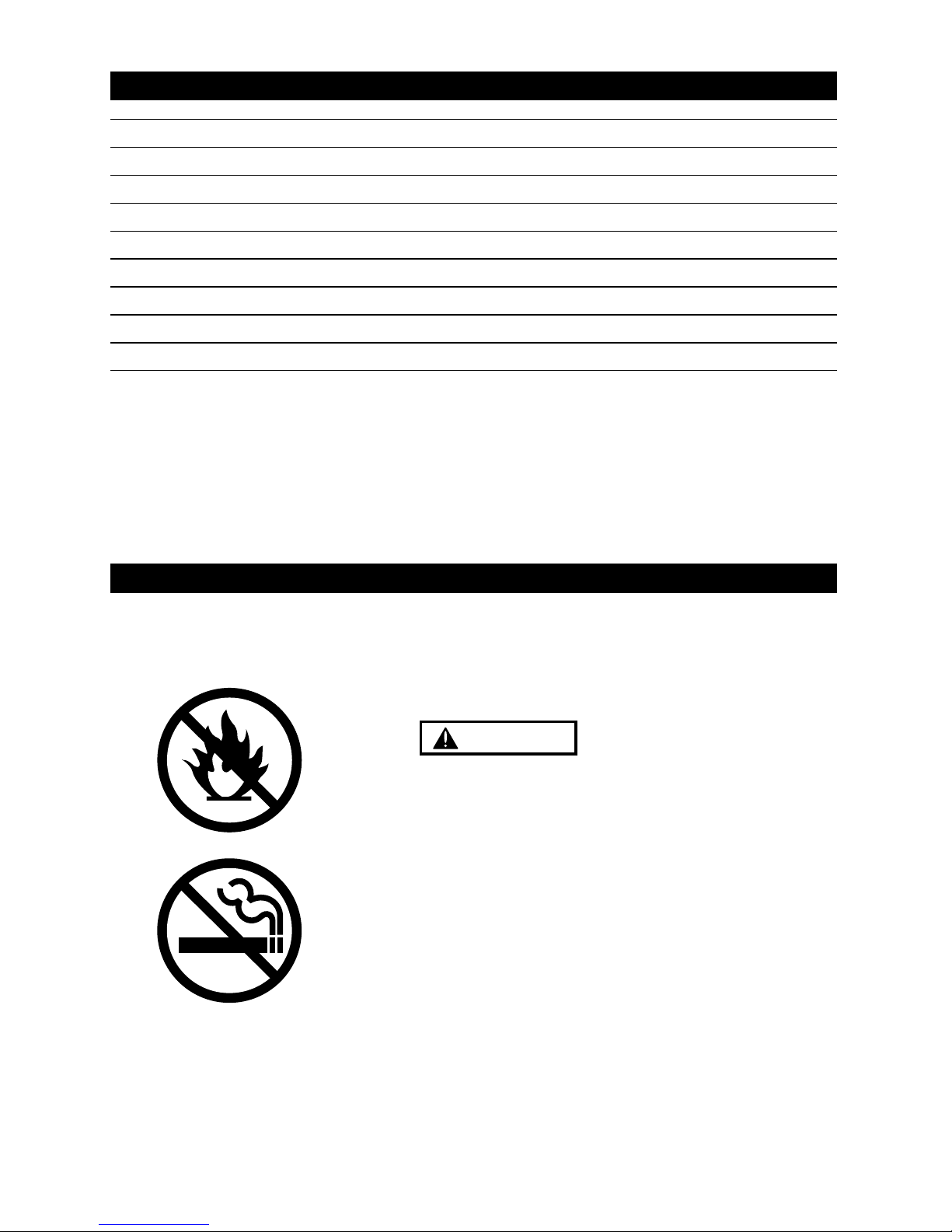
3. Engine Starting
4. Operation
• Push the primer pump several times until
overflown fuel flows out. (Fig.1)
• Close the choke lever(Fig.2), and move the
throttle lever 1/4~1/3 open position.
• Pull the starter(knob) quickly until first firing
noise. (Fig.3)
• Open the choke(Fig.2), throttle idle~1/4 open
• Pull the starter quickly
• Operate engine for a few minutes for the
warming up.
• In case of engine warm condition, choking may
not be necessary.
• Over choking may cause starting difficulty due
to wet spark plug.
In this case change spark plug or dry it, and
remove fuel rest in the cylinder by pulling
starter.
IMPORTANT
• This engine is already tuned up to get high
power and high speed, and needs correct
maintenance to keep such high performance.
• The details for operation may be described in
the separate owners manual to be issued by car
manufacturer.
• Be sure to have the engine cool down for 30
seconds at idle speed after full throttle running.
Fig.1
Choke
Lever
Open
Close
Throttle Lever
Fig.2
Fig.3
4
Page 5

5. Maintenance
1) MAINTENANCE CHART
Before Every Every
Items Action Use 25 hours 100 hours Note
Leakage,
Check ✔
Damage/Crack
Idling Speed Check/Adjust ✔✔✔
Air-cleaner Check/Cleaning ✔✔ Replace if necessary
Spark Plug(gap) Check/Adjust ✔✔ ↑
Cylinder(barrel) Check/Cleaning ✔✔ ↑
Piston, Ring Check/Cleaning ✔✔ ↑
Muffler & Bolt Check/Cleaning ✔✔✔ ↑
Bearings Check/Cleaning ✔✔ ↑
Crank Shaft Check/Alignment ✔ ↑
2) SPECIFICATIONS AND TECHNICAL DATA
Items Unit Specifications Remarks
Bore x Stroke mm 32 x 28
Displacement cm
3
22.5
Effective Compression Ratio 8.8
Type Walbro WT
Carburetor
Venture(mm) ø12.7
Starting Recoil Starter
Type TCI
Ignition
Timing BTC 30°/8000rpm
Standard CMR7H NGK
Spark Plug Option(For Race) CR8HVX NGK
with Terminal Nut
Clutch Engagement Speed rpm 6000
No load max Speed rpm 19500
Idling Speed rpm 4000
Without Air Cleaner
Max. Power kW/rpm 2.10/14000
and Muffler
Max. Torque N.m/rpm 1.72/10000 ↑
Fuel Consumption g/kW·h 680 (500g/ps·h) ↑
Carburetor H 1 3/8 ± 1/4
Standard setting L 1 1/4 ± 1/4
5
Page 6

5. Maintenance
3) MAINTENANCE SPECIFICATIONS
Items Standard Limit Measuring Device Remarks
Compression (kg/cm2) 8.8 7.3 Compression Gage
Bore (mm) ø32 Plating damaged Eye Checking
Diameter (mm) ø31.97 ø31.87 Micro Meter
Piston Ring
1.01 1.11 Thickness Gauge
Groove width (mm)
Piston Pin Hole (mm) ø8.01 ø8.05 Cylinder Gauge
Clearance between Micro Meter
0.03~0.06 0.15
Piston and Cylinder (mm) Cylinder Gauge
Clearance between
0.02~0.04 0.1 Thickness Gauge
Groove and Piston Ring (mm)
End Gap (mm) 0.05~0.25 0.5 Thickness Gauge
Width (mm) 0.98 0.93 Micro Meter
Piston Pin Diameter (mm) ø8 ø7.98 Micro Meter
Connecting Rod Small end (mm) ø11 ø11.05 Cylinder Gauge
Crankshaft Dia. at Main Bearing (mm) ø12 ø11.98 Micro Meter
Eccentricity (mm) — 0.07 Dial Gauge
Axial Play (mm) — 0.5 Thickness Gauge
Gritty or
Main Bearing — —
Feels Flat Spot
At the skirt end and
the right angle to
the piston pin.
When inserted in a
new cylinder.
Piston CylinderPiston Ring
4) CARBURETOR
Items Standard Limit Measuring Device Remarks
Metering Lever set (mm) 1.65 ± 0.16 Vanier
Inlet Valve Opening Pressure (kg/cm2) 1.3~2.3 Leak Tester
Inlet Valve Closing Pressure (kg/cm2) 0.7~1.7 Leak Tester
6
Page 7

5. Maintenance
5) IGNITION SYSTEM
Items Standard Limit Measuring Device Remarks
Spark Plug Air Gap (mm) 0.6~0.7 0.7 Thickness Gauge
Ignition Coil/Flywheel Air Gap (mm) 0.3 0.4 Thickness Gauge
Primary 0.7 — Volt Meter
Secondary 6100 — Volt Meter
Reading between
primary terminal and
iron core.
Reading between
sparking cord end and
iron core.
6) TIGHTENING TORQUE
Items Screw Size Standard (kg·cm) Limit (kg·cm) Remarks
Carburetor M5 (P=0.8) 35 30~40
Insulator M5 (P=0.8) 35 30~40 with Locktight glue
Clutch M6 (P=1.0) 65 50~80
Rotor M8 (P=1.0) 130 100~150
Cylinder M5 (P=0.8) 70 60~80
Crankcase M5 (P=0.8) 65 50~80
Spark Plug M10 (P=1.0) 110 100~120
Muffler M5 (P=0.8) 90 70~100
Fan Cover M5 (P=0.8) 35 30~40
Ignition Coil M4 (P=0.7) 33 25~40
Starter Case M4 (P=0.7) 13 10~15
Tapping Screw TP 4.3 25 20~30
Coil
Resistance
(Ω)
7
Page 8

6. Special Tools
7) SPECIAL TOOLS
Part Name Part No. External Appearance Usage
1 Puller Assy 2890-96100 To remove rotor.
2 Piston Stopper 4810-96220
3 Rod Assy 1101-96220 To remove/install piston pin.
4 Air Gap Gauge 3330-97310 To set ignition coil.
5 Hex Wrench 3304-97611
6 Snap Ring Pliers 5500-96110 To remove snap ring.
To hold crankshaft when
disassembling/assembling
clutch and rotor.
For socket screw of Hex.
3mm, 4mm and 5mm.
8
Page 9

7. Service Guide
1) REMOVING CLUTCH SHOE
1. Remove the housing and plug cap.
2.Remove the spark plug and fit the
stopper(4810-96220) into the plug hole.
3. Remove clutch bolts(14mm Hex.).
2) REMOVING ROTOR (FAN)
4. Remove the rotor nut(12mm Hex.).
5. Remove the rotor using the puller assy (2890-
96100). Apply 8mm puller bolts.
3) ASSEMBLING ROTOR
Insert the gauge(3330-97310) in between the
rotor magnet metal and the coil.Tighten screws
while pressing the coil against the rotor.
Gap Specification 0.3 ~ 0.4mm
Clutch Bolt
(14mm Hex.)
Rotor Nut
17mm Hex.
Puller Bolts
Puller
Rotor
Wrench
Air Gap Gauge
Ignition Coil
9
Page 10

7. Service Guide
4) REMOVING PISTON PIN
1. Remove snap rings from both sides of the
piston pin.
2. Engage the rod assy(1101-96220) to the
piston pin and gently tap with a plastic hammer
to push out the pin while holding piston firmly.
Hard hammering may damage the big end of
the connecting rod.
5) INSTALLING PISTON
1. Make sure to point the arrow mark on the
piston to the exhaust side.
2. Fit the circlip in the groove so as to face the
end gap below.
Deformed circlip may come off during engine
operation and damage the engine.
6) CARBURETOR ADJUSTMENT
The carburetor comes with a standard setting, it
is for optimum performance under the barometric
pressure and climatic conditions at factory, so it
may be re-adjusted according to load applied.
Idle rpm : 4000 ± 300 rpm (STD Spring)
H needle : 1 3/8 ± 1/4
L needle : 1 1/4 ± 1/4
NOTE
NOTE
Plastic
Hammer
Rod Assy
Piston
Arrow Mark
Circlip
End Gap
Piston
H needle
L needle
Idle Screw
10
Page 11

9. Trouble Shooting
1) ENGINE DOES NOT START
Description Cause Countermeasure
No spark in the spark plug
Spark Plug 1. Wet spark plug electrodes Make them dry
2. Carbon deposited on the electrodes Cleaning
3. Insulation failure by insulator damage Exchange
4. Inproper spark gap Adjust to 0.6~0.7mm
5. Burn out of electrodes Exchange
Magneto 1. Ignition coil inside failure Exchange
2. Damaged cable sheath or disconnected cable Exchange or repair
Switch 1. Switch is OFF ON the switch
2. Switch failure Exchange
3.Primary wiring earthed Repair
Sparks appear in the spark plug
Compression & 1. Over sucking of fuel Drain excess fuel
fueling is normal 2. Too rich fuel Adjust carburetor
3. Overflow Carburetor adjust or exchange
4. Clogging of air cleaner Wash with mixed gasoline
5. Faulty fuel Change with proper fuel
Fueling normal but 1. Worn out cylinder, piston, or piston ring Exchange
poor compression 2. Gas leakage from cylinder and crank case gasket Apply liquid gasket and reassemble.
No fuel supply 1. Choked breather air hole Cleaning
2. Clogged carburetor Cleaning
3. Clogged fuel filter Exchange fuel filter
11
2) LACK OF POWER OR UNSTABLE RUNNING
Description Cause Countermeasure
Compression is normal 1. Air penetration from fuel pipe joints, etc Secure connection
and no misfire 2. Air penetration from intake tube joint or
Change gasket or tightening screws
carburetor joint
3. Water in fuel Change with good fuel
4. Piston start to seizure Replace piston(and cylinder)
5. Muffler choked with carbon Cleaning
Overheating 1. Fuel too lean Adjust carburetor
2. Clogging of cylinder fin with dust Cleaning
3. Poor fuel quality Exchange with proper fuel
4. Carbon deposited in the combustion chamber Cleaning
5. Spark plug electrode red hot Thoroughly clean, adjust spark gap
[ 0.6~0.7(0.023~0.028in) ]
Others 1. Dirty air cleaner Wash with mixed gasoline
2. Over loading Reduce load
Page 12

10. Parts list
12
Page 13

Model Name & Cord
Key# Part Number Description Q'ty
GR23101 GR23102 GR23103 GR23104
Remarks
G230RC G230RC1 G230RC2 G230RC3
10. Parts list
13
1 T2070-12110 CYLINDER 1 ●●●●
2 T2070-12210 GASKET 1 ●●●●
3 01252-30522 BOLT 2 ●●●●M5x22L
4 1148-13161 INSULATOR 1 ●●●●
5 1140-13151 GASKET, INSU 1 ●●●●
6 3330-14121 GASKET, CARB 1 ●●●●
7 0263-90520 SCREW 2 ●●●●M5x20L
8 T2070-15110 MUFFLER 1 ●●––
9 01252-30550 BOLT 2 ●●– – M5x50L
10 1140-13141 GASKET, MUFFLER 1 ●●●●
11 1850-32160 SCREW 1 ●●– – M4x12L
12 T2070-21101 CRANKCASE-C 1 ●●●●
13 2629-21130 • PIN 3 ●●●●
14 5500-21141 GASKET, CASE 1 ●●●●
15 1155-21240 BEARING 2 ●●●●
16 2169-21210 SEAL 1 ●●●●
17 1850-21220 SEAL 1 ●●●●
18 04065-02812 RING 1 ●●●●
19 01252-30530 BOLT 4 ●●●●M5x30L
20 T2070-41110 PISTON 1 ●●●●
21 T2070-41210 RING 1 ●●●●
22 1101-41310 PIN 1 ●●●●
23 1260-41320 RING 2 ●●●●
24 5500-41410 BEARING 1 ●●●●
25 1101-41340 WASHER 2 ●●●●
26 T2070-42000 CRANKSHAFT-C 1 ●●●●
27 1650-43230 NUT 1 ●●●●M8x1.0
28 1000-43240 KEY 1 ●●●●
29 1140-43250 SIM 1 ●●●●
30 1140-51111 SHOE 2 ●●●–
31 T2070-51220 SPRING 1 ●●●– (6000rpm IN)
32 1140-51250 SCREW 2 ●●●– M6x22L
33 1140-51230 WASHER 2 ●●●–
34 1140-51242 WASHER 2 ●●●–
35 1140-21162 CASE, CLUTCH 1 ●●●–
36 3350-15250 BOLT 4 ●●●– M5x16L
37 1140-55310 PLATE 1 ●●●–
38 0224-30614 BOLT 1 ●●●– M6x14L
39 T2070-71110 ROTOR 1 ●●●●
40 T2070-71200 COIL-A 1 ●●●●
42 T2070-72210 CAP 1 ●●●●
43 1400-72121 SPRING 1 ●●●●
44 5500-72130 GROMMET 1 ●●●●
45 1260-71261 SPACER 2 ●●●●
46 3350-14150 BOLT 2 ●●●●M4x20L
47 T2070-75101 RECOIL-A 1 ●●●●
48 T2070-75110 • CASE 1 ●●●●
49 5990-75120 • SPRING, SPIRAL 1 ●●●●
50 5990-75131 • REEL 1 ●●●●
51 5990-75141 • RATCHET 1 ●●●●
52 5990-75151 • SPRING, BREAK 1 ●●●●
53 5990-75270 • SCREW 1 ●●●●
54 5990-75160 • RETAINER 1 ●●●●
55 5990-75170 • WASHER 1 ●●●●
56 1861-75180 • ROPE 1 ●●●●
57 1490-75181 • KNOB 1 ●●●●
58 0263-90416 SCREW 4 ●●●●M4x16L
59 T2070-81000 CARBURETOR-A 1 ●●●●WT-603
60 3306-81380 • SCREEN 1 ●●●●
61 3080-81120 • COVER 1 ●●●●
62 3310-81130 • SCREW 1 ●●●●
63 3304-81140 • GASKET 1 ●●●●
64 1172-81150 • DIAPHRAGM 1 ●●●●
65 1751-81470 • GASKET 1 ●●●●
Page 14

10. Parts list
14
Model Name & Cord
Key# Part Number Description Q'ty
GR23101 GR23102 GR23103 GR23104
Remarks
G230RC G230RC1 G230RC2 G230RC3
66 3310-81260 • DIAPHRAGM 1 ●●●●
67 T2070-81210 • BODY-A 1 ●●●●
68 1751-81520 • COVER 1 ●●●●
69 1751-81510 • PUMP 1 ●●●●
70 2867-81270 • SPRING 1 ●●●●
71 3356-81310 • VALVE inlet 1 ●●●●
72 1480-81420 • PLUG welch 1 ●●●●
73 3310-81230 • LEVER 1 ●●●●
74 3310-81240 • SCREW 1 ●●●●
75 3310-81250 • PIN 1 ●●●●
76 2630-81330 • SCREW 1 ●●●●
77 3350-81380 • SPRING 1 ●●●●
78 T2070-81370 • SHAFT throttle 1 ●●●●
79 2670-81410 • SPRING 1 ●●●●
80 2880-81470 • SCREW 2 ●●●●
81 3310-81340 • VALVE throttle 1 ●●●●
82 3310-81360 • SCREW 1 ●●●●
83 1790-81440 • LEVER throttle 1 ●●●●
84 1148-81390 • RING 1 ●●●●
85 T2070-81460 • SHAFT choke 1 ●●●●
86 2670-81450 • VALVE choke 1 ●●●●
87 3350-81350 • SPRING 1 ●●●●
88 3350-81220 • BALL 1 ●●●●
89 1148-81530 • SCREW 4 ●●●●
90 1491-81160 • SPRING 1 ●●●●
91 1148-81171 • NEEDLE low speed 1 ●●●●
92 3080-81320 • SPRING 1 ●●●●
93 T2070-81330 • NEEDLE high speed 1 ●●●●
94 3304-81450 • SCREEN 1 ●●●●
95 3304-81441 • RING 1 ●●●●
96 3360-81440 • PLUG 1 ●●●●
98 T2070-82410 LEVER 1 ●●●●
99 T2070-82510 SPACER 1 ●●●●
100 0263-90560 SCREW 2 ●●– – M5x60L
101 0263-90550 SCREW 2 – – ●●M5x50L
102 T2070-82000 CLEANER-A 1 ●●––
103 5731-82011 • HOUSING 1 ●●––
104 5730-82040 • COVER 1 ●●––
105 1750-82020 • FILTER 1 ●●––
106 5730-82060 • SLEEVE 2 ●●––
107 T2070-31110 COVER, FAN 1 ●●●●
108 3310-12281 BOLT 4 ●●●●M5x20L
109 T2070-32100 COVER-A 1 ●●●●
110 1850-32160 SCREW 1 ●●●●M4x12L
111 1900-31410 SCREW 2 ●●●●TP4.5x18L
112 T1108-73110 SPARKPLUG 1 ●●●●
113 T2070-72200 SWITCH-A 1 ●●●●
114 T2070-75410 LABEL, RECOIL 1 ● – ●●
115 T2071-75410 LABEL, RECOIL 1 – ● ––
116 1726-85004 TANK-A 1 – ● ––
117 5601-85201 • CAP-A 1 – ● ––
118 1726-85601 • PIPE COMP 1 – ● ––
119 5500-85400 • FILTER 1 – ● ––
120 1260-85460 • CLIP 1 – ● ––
121 1799-85400 PIPE COMP 1 ● – ●●
122 5500-85400 FILTER 1 ● – ●●
123 1260-85460 CLIP 1 ● – ●●
124 T3039-91310 SOCKET 1 ●●●●
125 T2070-93110 MANUAL 1 ●●●●
126 2890-96100 PULLER-A 1 ●●●●OP
127 4810-96220 STOPPER 1 ●●●●OP
128 T2070-98100 SPARKPLUG 1 ●●●●OP
(NGK CR8HVX with Terminal Nut)
129 1764-51220 SPRING 1 ●●●– OP (5000rpm IN)
Page 15

11. Warranty
15
1) SCOPE OF APPLICATION
This engine manufactured by Komatsu Zenoah Co. (hereinafter referred as KZ) and
sold to the user directly or through distributor/manufacturer, shall entitle to be covered
by this warranty.
2) LIMIT OF WARRANTY
KZ warrants that ;
1. The quality disclosed in the specifications.
2. The engine which shall be considered defective by KZ, caused by material or
production fault.
3) LIMITS OF COMPENSATION
1. KZ compensates such quality, material and production faults by repairing or
replacing.
2. KZ shall not compensate any other accompanied or benefit losses caused to user
and distributor/manufacturer by such faults and through repairing or replacing.
4) TERMS OF WARRANTY
3 months after purchased by user subject to 12 months from produced month.
5) EXEMPT FROM WARRANTY
KZ shall not warrant this engine even if the fault has been caused during the period of
terms of warranty, in case of that ;
1. Any faults, failures caused from neglect of this OWNER'S SERVICE MANUAL for
proper operation and maintenance.
2. Any modifications not approved by KZ.
3. Normal abrasion and deterioration.
4. Consuming parts.
Page 16

Head Office : 1-9 Minamidai, Kawagoe-city, Saitama, 350-1192 Japan
Phone: (+81)492-43-1117 Fax: (+81)492-43-7197
 Loading...