

Page 1
BK3420FL
848G5C93A0 (704)
BRUSHCUTTER
OWNER’S MANUAL
• Before using our products, please read
this manual carefully to understand the
proper use of your unit.
• Keep this manual handy.
Caution
Page 2

2
SAFETY FIRST
Instructions contained in warnings within this
manual marked with a symbol concern
critical points which must be taken into
consideration to prevent possible serious
bodily injury, and for this reason you are
requested to read all such instructions
carefully and follow them without fail.
■ NOTES ON TYPES OF WARNINGS IN THE
MANUAL
This mark indicates instructions which must be
followed in order to prevent accidents which could
lead to serious bodily injury or death.
This mark indicates instructions which must be
followed, or it leads to mechanical failure,
breakdown, or damage.
This mark indicates hints or directions useful in the
use of the product.
NOTE
IMPORTANT
WARNING
Contents
1. Parts Location …………………………………3
2. Symbols On The Machine ……………………3
3. Safety Precautions ……………………………4
4. Set Up …………………………………………7
5. Fuel ……………………………………………12
6. Operation ……………………………………13
7. Maintenance …………………………………19
8. Troubleshooting ……………………………26
9. Specifications ………………………………28
Page 3
3
1. Muffler
2. Fuel tank
3. Fuel tank cap
4. Shoulder frame
5. Shoulder belt
6. Hanging belt
7. Air cleaner
8. Spark plug
9. Fuel cock
10. Carburetor
11. Recoil starter
12. Choke lever
13. Gear case
14. Tangle-prevention cover
15. Blade (Blade is not included)
16. Blade cover
17. Debris guard
18. Main pipe
19. Loop handle
20. Throttle lever
21. Right-hand grip
22. Throttle wire
23. Wire clamp
24. Engine stopping switch
25. Flexible shaft
2. Symbols on the machine
For safe operation and maintenance, symbols are carved
in relief on the machine. According to these indications,
please be careful not to take a mistake.
(a) The port to refuel the "MIX GASOLINE"
POSITION: FUEL TANK CAP
(b) The direction to close the choke
POSITION: AIR CLEANER COVER
(c) The direction to open the choke
POSITION: AIR CLEANER COVER
1. Parts Location
Page 4
4
■ BEFORE USING THE MACHINE
a. Read this owner's manual carefully to
understand how to operate this unit properly.
b. This product has been designed for use in
trimming grass, and it should never be used for
any other purpose since doing so could result
in unforeseen accidents and injuries occurring.
c. You should never use this product when under
the influence of alcohol, when suffering from
exhaustion or lack of sleep, when suffering
from drowsiness as a result of having taken
cold medicine, or at any other time when a
possibility exists that your judgment might be
impaired or that you might not be able to
operate the product properly and in a safe
manner.
d. Avoid running the engine indoors. The exhaust
gases contain harmful carbon monoxide.
e. Never use your product under circumstances
like those described below:
1. When the ground is slippery or when other
conditions exist which might make it not
possible to maintain a steady posture while
using the product.
2. At night, at times of heavy fog, or at any
other times when your field of vision might
be limited and it would be difficult to gain a
clear view of the area.
3. During rain storms, during lightning storms,
at times of strong or gale-force winds, or at
any other times when weather conditions
might make it unsafe to use this product.
f. When using this product for the first time,
before beginning actual work, learn to handling
the product from skilled worker.
g. Lack of sleep, tiredness, or physical exhaustion
results in lower attention spans, and this in turn
leads to accidents and injury.
Limit the amount of time over which the product
is to be used continuously to somewhere
around 30~40 minutes per session, and take
10~20 minutes of rest between work sessions.
Also try to keep the total amount of work
performed in a single day under 2 hours or
less.
h. Be sure to keep this manual handy so that you
may refer to it later whenever any questions
arise.
i. Always be sure to include this manual when
selling, lending, or otherwise transferring the
ownership of this product.
j. Never allow children or anyone unable to fully
understand the directions given in this manual
to use this product.
■
WORKING GEAR AND CLOTHING
a. When using your product, you should wear
proper clothing and protective equipment as
follows.
(1) Helmet
(2) Protection goggles or face protector
(3) Thick work gloves
(4) Non-slip-sole work boots
(5) Ear protectors
b. And you should carry with you things as
follows.
1. Attached tools and files
2. Properly reserved fuel
3. Spare blade
4. Things to notify your working area (Rope,
warning signs)
3. Safety Precautions
Page 5
5
person using the product should be considered
a hazardous area into which no one should
enter while the product is in use, and when
necessary yellow warning rope, warning signs
should be placed around the work area. When
work is to be performed simultaneously by two
or more persons, always check the presence
and locations of others so as to maintain a
distance each person sufficient to ensure
safety.
c. Make sure that there are no loose screws or
bolts, fuel leaks, ruptures, dents, or any other
problems which might interfere with safe
operation. Be especially careful to check that
there is nothing wrong with the blades or with
the joints by which the blades are attached to
the product.
d. Never use blades that are bent, warped,
cracked, broken or damaged in any way.
e. Keep the blade always sharp.
f. Filing the cutting edges, keep the end corner
sharp and round the root of the edge.
g. Check the bolt to fasten the blade and be sure
the blade turns smoothly without abnormal
noise.
■ NOTES ON STARTING THE ENGINE
1. Take a careful look around to make sure that
no obstacles exist within a perimeter of 15m or
less around the product.
2. Place the body of the product onto the ground
in a flat clear area and hold it firmly in place so
as to ensure that neither the blades nor the
throttle come into contact with any obstacles
when the engine starts up.
3. Place the throttle into the idling position when
starting the engine.
4. After starting up the engine, if the blades
continue to rotate even after the throttle has
been moved fully back, turn off the engine and
check the throttle wire and other parts.
■
KICKBACK SAFETY PRECAUTIONS
•A dangerous reaction may occur when the
spinning blade contacts a solid object in the
critical area. It is called Kick back. As a result,
5. Whistle (for collaboration or emergency)
6. Hatchet or saw (for removal of obstacles)
c. Never use your product when wearing pants
with loose cuffs, when wearing sandals, or
when barefoot.
■ WARNING CONSIDERING HANDLING OF
FUEL
a. The engine of this product is designed to run
on a mixed fuel which contains highly
flammable gasoline. You should never store
cans of fuel or refill the fuel tank in any place
where there is a boiler, stove, wood fire,
electrical sparks, welding sparks, or any other
source of heat or fire which might ignite the
fuel.
b. Smoking while operating the product or refilling
its fuel tank is extremely dangerous. Always
be sure to keep lit cigarettes away from the
product at all times.
c. When refilling the tank always turn off the
engine first and take a careful look around to
make sure that there are no sparks or open
flames anywhere nearby before refueling.
d. If any fuel spillage occurs during refueling, use
a dry rag to wipe up spills before turning the
engine back on again.
e. After refueling, screw the fuel cap back tightly
onto the fuel tank and then carry the product to
a spot 3m or more away from where it was
refueled before turning on the engine.
■ THINGS TO CHECK BEFORE USING THE
PRODUCT
a. Before beginning work, look around carefully to
get a feel for the shape of the land, or grass to
be trimmed, and whether or not there are any
obstacles which might get in the way while
working, and remove any obstacles which can
be cleared away.
b. The area within a perimeter of 15m of the
3. Safety Precautions
Page 6

6
3. Safety Precautions
h. Never touch the muffler, spark plug, or other
metallic parts of the engine while the engine is
in operation or immediately after shutting down
the engine. Doing so may result in serious
burns.
i. When you finish cutting in one location and
wish to continue work in another spot, turn off
the engine and turn the unit as the blade faces
away from your body.
■ MAINTENANCE SAFETY PRECAUTION
a. Perform the maintenance and checking
operations described in this manual at regular
intervals. If any parts must be replaced or any
maintenance or repair work not described in
this manual must be performed, please contact
a representative from the store nearest
KOMATSU ZENOAH authorized servicing
dealer for assistance.
b. Under no circumstances should you ever take
apart the product or alter it in any way. Doing
so might result in the product becoming
damaged during operation or the product
becoming unable to operate properly.
c. Always be sure to turn off the engine before
performing any maintenance or checking
procedures.
d. When sharpening, removing, or reattaching the
blade, be sure to wear thick, sturdy gloves and
use only proper tools and equipment to prevent
injury.
e. When replacing blade or any other parts or
when replacing the oil or any lubricants, always
be sure to use only KOMATSU ZENOAH
products or products which have been certified
by KOMATSU ZENOAH for use with the
product.
the operator can lose control of the unit which
can cause serious or fatal injury.
Avoid kickback, observe the safety precautions
below strictly.
1. Keep the cutting blades clear of fances, posts,
wires, and rocks to prevent kickback and
damage to the blades.
2. When using your product, do not grip other
parts except the handles.
3. When using your product, never take your eyes
off. If you need to, place the throttle into the
idling position.
4. When using your product, do not let the unit get
closer to your feet nor raise the unit above your
waist.
■ NOTES ON TRANSPORTATION
a. Make sure the appropriate blade cover is in
place.
b. When transporting by car, fix the unit firmly
using a rope. Do not transport by bicycle or
motorbike because it is dangerous.
c. Never transport the product over rough roads
over long distances without first removing all
fuel from the fuel tank, as doing so might cause
fuel to leak from the tank.
■
OPERATION SAFETY PRECAUTIONS
a. Grip the handles of the product firmly with both
hands. If you suspend the work, place the
throttle into the idling position.
b. Always be sure to maintain a steady, even
posture while working.
c. Maintain the speed of the engine at the level
required to perform cutting work, and never
raise the speed of the engine above the level
necessary.
d. If the grass gets caught in the blade during
operation, or if you need to check the unit or
refuel the tank, always be sure to turn off the
engine.
e. If the blade touches a hard object like a stone,
immediately stop the engine and check if
something is wrong with the blade. If so,
replace the blade by new one.
f. If someone calls out while working ,always be
sure to turn off the engine before turning
around.
g. Never touch the spark plug or plug cord while
the engine is in operation. Doing so may result
in being subjected to an electrical shock.
Page 7
7
4. Set Up
• Assemble each part correctly. Wrong assembly
might cause an accident.
• If you cannot do the assembling yourself, consult
the shop where you bought this product.
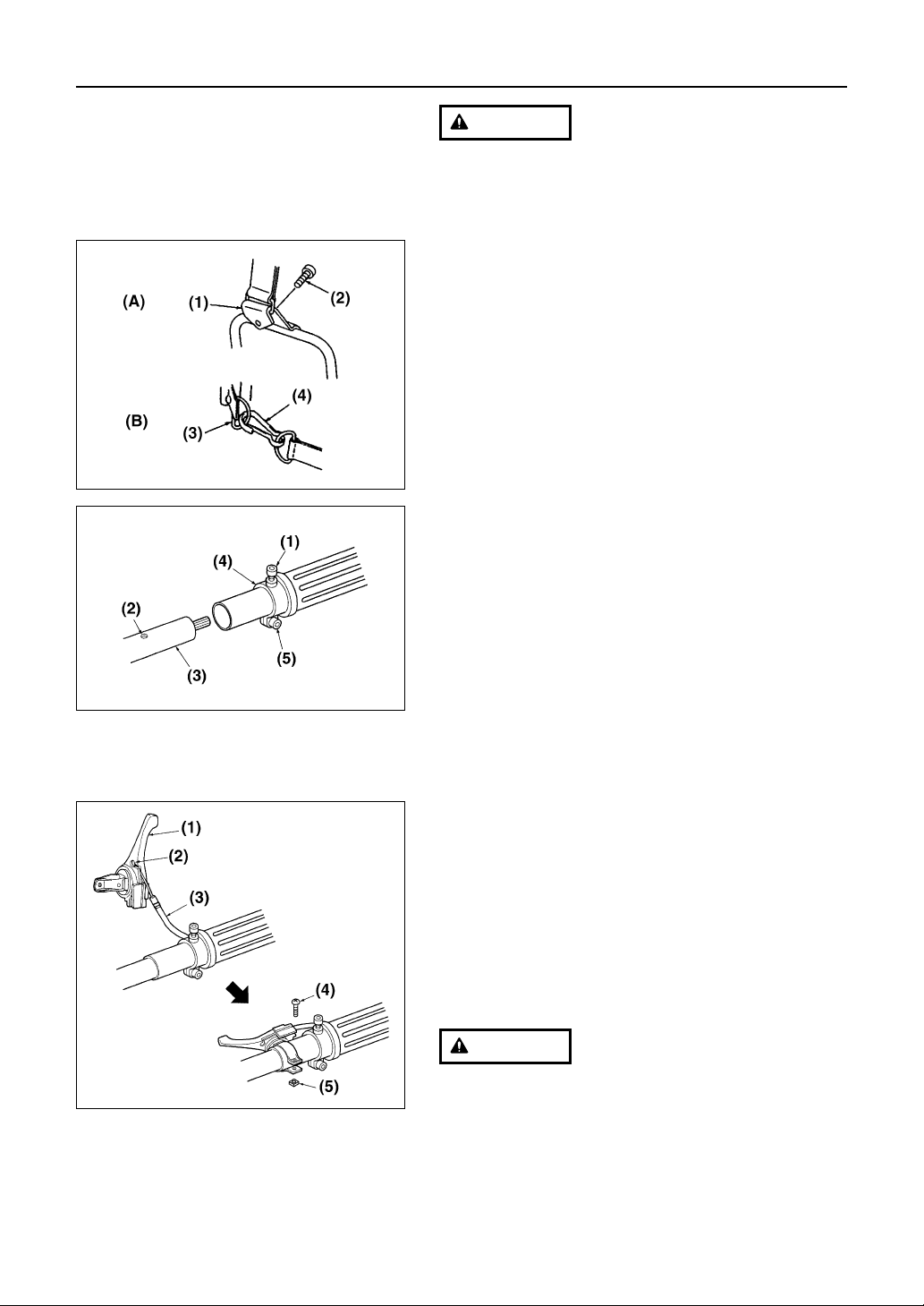
■ ATTACHING THE SHOULDER STRAP (SE1)
1. Pass the ring of the shoulder strap through the
hook(A) and fix it by the bolt securely.
2. Set the hook(B) of each shoulder strap to the D-rings
on the frame.
(A) UPPER SIDE (B) LOWER SIDE (1) Hook (A)
(2) Bolt (3) D-ring (4) Hook (B)
■ CONNECTING THE FLEXIBLE SHAFT
1. Remove the clamping bolt (M5xL10) in the center of
the end of the joint, and loosen the fastening bolt
(M5xL20). (SE2)
2. Insert the main pipe into the joint while turning it
clockwise and counterclockwise slightly. (SE2)
3. Align the safety-lock hole of the joint with the hole of
the main pipe, screw the clamping bolt and fasten it
tightly. (SE2)
4. Tighten the fastening bolt of the joint, and fix the main
pipe firmly. (SE2)
[Tightening torque]
4.9 to 7.8 N-m (0.5~0.8 kg-m)
(1) Clamping bolt (M5xL10) (2) Safety-lock hole
(3) Main pipe (4) Joint (5) Fastening bolt (M5xL20)
5. Hook the cable end into the hole of the throttle lever.
And set the cable in the lever as shown in the picture.
(SE3)
6. Attach the lever as shown in the picture and screw it
securely. (SE3)
(1) Throttle lever (2) Hole (3) Throttle cable
(4) Screw (5) Nut
After fitting the wire, check if the wire sleeve is
correctly fitted to the wire stopper. It is dangerous if
the wire sleeve is out of the wire stopper because
the engine speed will not decrease even if the
throttle lever is released.
WARNING
SE1
SE2
SE3
WARNING
Page 8
8
4. Set Up
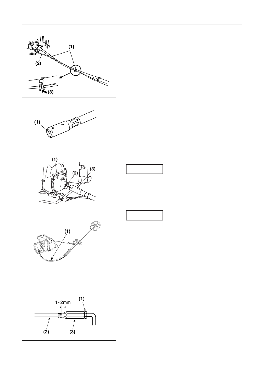
7. Align the throttle cable along with the liner and tie it
with band. (SE4)
(1) Band (2) Throttle cable (3) Tie loosely
8. Stretch the main pipe and the flexible shaft straight,
thrust the inner shaft into the main pipe while turning it
by hand, and connect the inner shaft to the shaft of the
main pipe. Unless the end of the inner shaft appears
from the flexible shaft, the inner shaft has been
correctly connected to the shaft of the main pipe.
(SE5)
(1) Inner shaft
9. Turn the hole at the end of the flexible shaft upward,
align the square hole of the clutch dram with the
direction of the inner shaft, and thrust the flexible shaft
into the clutch housing until you hear a click. (SE6)
(1) Clutch housing (2) Clutch dram square-hole (3) Hole
After connecting the inner shaft to the shaft of the main pipe,
try to pull out the flexible shaft by hand to make sure the
flexible shaft does not come off.
■ ADJUSTING THE PLAY OF THE THROTTLE WIRE
If you bend the flexible shaft, the amount of play of the
throttle wire changes. Adjust the play while keeping the
flexible shaft almost in the actual working condition. (SE7)
(1) Flexible shaft
The play of the throttle wire that extends out of the
carburetor with the throttle lever in its original place should
be 1 to 2 mm when lightly pulled by finger. If the play is too
large or small, readjust it as follows. (SE8)
1. Loosen the lock nut and adjust the throttle wire with
the wire brace so that the amount of play is
appropriate. The play becomes larger when the wire
brace is turned clockwise, and becomes smaller when
the wire brace is turned counterclockwise.
2. Tighten the lock nut after adjusting the play, and fix
the wire brace.
(1) Lock nut (2) Throttle wire (3) Wire brace
IMPORTANT
IMPORTANT
SE6
SE7
SE8
SE5
SE4
Page 9
9
4. Set Up
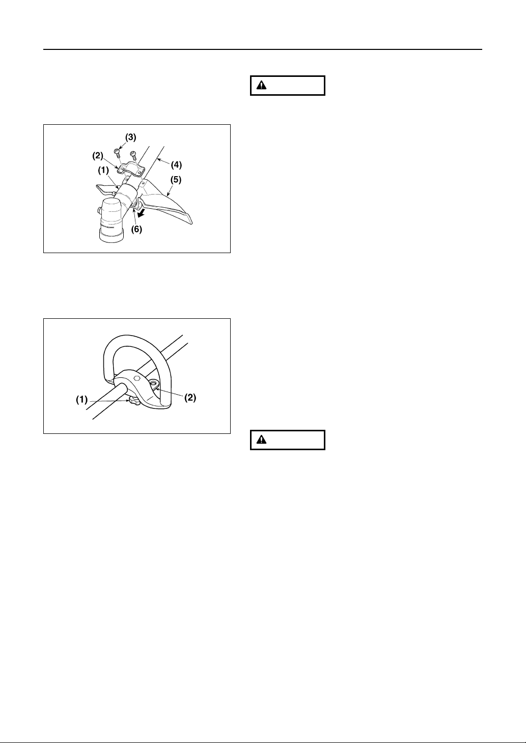
■ INSTALLING DEBRIS GUARD
Do not use this machine without the debris guard.
Fit the top of the debris guard to the gear case, install the
debris guard on the main pipe with the accessory clamp,
and tighten the debris guard evenly with two Phillips screws
(M5xL25). (SE9)
[Tightening torque]
2.6 to 4.9 N-m (27 to 50 kgf-cm)
(1) Gear case (2) Clamp (3) Phillips screw (M5xL25)
(4) Main pipe (5) Safety-guard cover
(6) Fit this part to the gear case.
■ MOUNTING THE HANDLE
1. Mount the loop handle on the main pipe in accordance
with the serial-number label. Turn the grip and tighten
it slightly, then fasten the hanger plate together in the
position shown in (SE10).
2. Adjust the position of the loop handle to the position
where you can work easily, and tighten the loop
handle firmly.
•Tighten the grip firmly. If the grip becomes loose,
it might move while you are working, causing
danger.
• Do not loosen or twist the grip while you are
working.
•Always stop the engine and make sure the blade
has stopped before adjusting the position of the
loop handle.
(1) Grip (2) Hanger plate
WARNING
SE9
SE10
WARNING
Page 10
10
4. Set Up
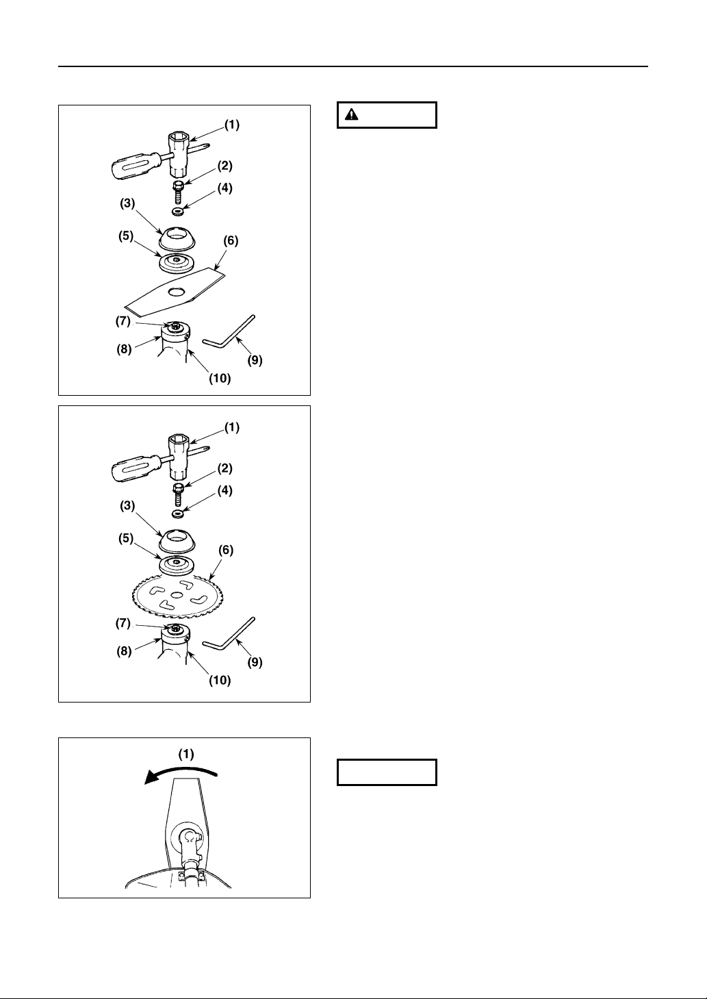
■ INSTALLING THE BLADE (available as an option)
• Do not install or remove the blade while the engine
is in operation.
• Use ZENOAH’s genuine replacement blades and
metal fixtures when installing the blade.
•When installing or removing the blade, fix the
machine securely, and wear robust gloves.
• The blade turns counterclockwise (viewed from
the gear case). When using an inside-out blade,
check the direction of the blade before installing it.
In particular, if you install a chip saw in the wrong
direction, the chips might break and scatter.
INSTALLING THE METAL BLADE (SE11) (SE12)
1. Remove the blade mounting bolt which is temporarily
fastened in the gear shaft (and which can be loosened
by turning it clockwise as it is a left-handed bolt) and
the outer holder.
2. Put the blade on the blade rest plate with the blade
surface on which there is writing facing toward the
gear case, then fit the hole of the blade to the
projecting part of the blade rest plate correctly.
3. Put the outer holder into the gear shaft with its convex
surface facing toward the blade.
4. Put the bolt cover on the outer holder, stop the whirl of
the blade rest plate with the L-shaped round rod, and
put the spring washer into the blade mounting bolt
(left-handed bolt). Then, tighten the bolt firmly.
[Tightening torque]
14.7 to 19.6 N-m (150 to 200 kgf-cm)
(1) Socket wrench (2) Blade mounting bolt
(3) Bolt cover (4) Spring washer
(5) Outer holder (6) Blade
(7) Gear shaft (8) Blade rest plate
(9) L-shaped round rod (10) Gear case
Look at the blade from above, and make sure that the
direction in which the blade is mounted is correct.
(1) Rotating direction
IMPORTANT
SE12
SE13
SE11
WARNING
Page 11

11
4. Set Up
INSTALLING THE NYLON CUTTER (available as an
option) (SE14)
Since the resistance of the nylon cutter is larger than that of
the metal cutter, wrong operation of the nylon cutter will
cause the clutch to overheat, deform and be damaged.
When using the nylon cutter, carefully note the following.
• Use ZENOAH’s genuine nylon cutter. When using a
commercially-available nylon cutter, make sure that it
is no longer than 10 cm in external shape.
• Make sure that the length of the nylon cord is 17 cm or
shorter.
• Keep the engine rotating at high speed while working.
1. Install the blade rest plate and the outer holder on the
gear shaft correctly, and stop their whirl with the
accessory L-shaped round rod.
2. Screw the mounting bolt (M7 left-handed) attached to
the nylon cutter into the gear shaft, and tighten it firmly
with a wrench.
[Tightening torque]
14.7 to 19.6 N-m (150 to 200 kgf-cm)
3. Screw the main body of the nylon cutter into the
mounting bolt while fixing the blade rest plate with the
L-shaped round rod, and tighten the main body of the
nylon cutter firmly by hand.
(1) Main body of the nylon cutter
(2) L-shaped round rod (3) Gear case
(4) Blade rest plate (5) Outer holder
(6) Mounting bolt (7) Nylon cord
The bolt, washer, and other parts for mounting the blade are
required when using the metal blade. Keep them carefully
so as not to lose them.
NOTE
IMPORTANT
SE14
Page 12

12
5. Fuel
• Gasoline is very flammable. Avoid smoking or
bringing any flame or sparks near fuel.
•Wipe up all spills before starting the engine.
•Make sure to stop the engine and allow it cool
before refueling the unit.
• Keep open flames away from the area where fuel
is handled or stored.
• Never use oil for 4 cycle engine use or water cooled 2cycle engine.
• Never use "FUEL WITH NO OIL (RAW GASOLINE)".
• Never use fuel laced with water.
• Mixed fuels which have been left unused for a period
of one month or more may clog the carburetor or
result in the engine failing to operate properly. Put
remained fuel into an air-tight container and keep it in
the dark and cool room.
• Please ask for “mixed gasoline for air-cooled 2-cycle
engines” at your nearest gas station, or use fuel made
by putting unleaded gasoline for automobiles and aircooled 2-cycle engine oil into a mixing container in
accordance with the following ratios and then shaking
to mix well.
Mixing ratios:
When using Zenoah genuine 2-cycle oil (FC grade):
50:1 (100 ml of oil for
every 5 liters of gasoline)
When using commercially available 2-cycle oil (FB
grade):
25:1(160 ml of oil for
every 4 liters of gasoline)
IMPORTANT
WARNING
Page 13

13
6. Operation
OP1
■ REFUELING
•Refuel the fuel tank in a flat place outdoors. Avoid
smoking or bringing any flame or spark near the
fuel, and stub out any cigarette.
• When refueling the fuel tank while using this
machine, make sure to stop the engine and allow it
to cool before refueling the fuel tank.
• Make sure to tighten the fuel-tank cap firmly.
• Wipe up all fuel spills with a dry cloth before
starting the engine.
Fill the fuel tank to roughly 80% of its capacity.
If filled too full, the fuel may leak from the tank cap while
using this machine.
1. Place the brushcutter to be refueled in a flat place
outdoors, and make sure it is stable.
2. Unscrew the fuel-tank cap a little, and allow the
difference of atmospheric pressure between the inside
and outside of the fuel tank to equalize.
3. Remove the fuel-tank cap, and fill fuel little by little up
to roughly 80%.
4. After filling the fuel, close the fuel-tank cap tightly, and
make sure that the fuel does not leak.
(1) Tank cap
(2) Fuel tank
IMPORTANT
WARNING
Page 14

14
6. Operation
• Do not start the engine with the throttle
lever kept pulled because the blade will
immediately begin to move upon starting
the engine. When starting the engine, place
the machine on a flat and firm place, and
keep all objects away from the blade.
• When starting the engine, keep all objects
away from the machine so that the blade
does not touch the ground.
• If the blade continues to rotate even after
the throttle lever is returned to the idling
position, stop the engine and check the
idling adjustment screw of the throttle wire
and the carburetor.
• When the engine has started, make sure
that the blade does not move. If the blade
continues to move, stop the engine, and
check the idling adjustment screw of the
throttle wire and the carburetor.
• While using the machine, hold the grips of
the machine with both hands, and keep
your eyes on the blade.
• Do not touch the metal part of the engine
body and the muffler while using the
machine or immediately after stopping
using it, otherwise you might suffer burns.
• Do not touch the spark plug or plug cord
while using the machine, otherwise you
might suffer an electric shock.
If you repeat the starting operation with the choke
closed, the electrode of the spark plug may become
wet and the engine might not start. If this happens,
open the choke, set the throttle lever to the almost
fully-open position and pull out the starter rope
repeatedly, or try the starting operation again after
removing the spark plug and drying the electrode.
IMPORTANT
■ STARTING THE ENGINE
• Before starting the engine after filling with
fuel, move the machine at least 3 m away
from where it was refueled.
Starting the engine where the machine was
refueled might cause a fire.
• Do not start the engine indoors or in any
place which is not well ventilated.
Otherwise, you might suffer carbon
monoxide poisoning which could injure
you.
• Keep the throttle lever set always to the
idling position when starting or stopping
the engine, or moving the machine. If the
throttle lever is set to any position other
than the idling position, the blade will begin
to rotate, causing danger.
• The engine might start after a delay. Hold
the unit until it starts.
• Before starting the engine, check the entire
unit for troubles such as looseness in
installing the handle, malfunctioning of the
throttle lever, looseness in installing the
blade, and fuel leaks.
• When starting the engine, place the
machine on the ground and hold it securely.
Since the blade might touch the ground or
object near the machine, do not start the
engine while holding up the machine with
one hand.
WARNING
WARNING
WARNING
Page 15

15
6. Operation
1. Open the fuel cock. (OP2)
2. Raise the choke lever on the right of the air cleaner to
close the choke.
When you start the engine again immediately after stopping
it, pull out the starter rope while keeping the choke opened.
(1) Choke lever (2) Close (3) Open
(4) Fuel cock (5) Closed (6) Opened
3. Set the throttle lever to “idling”. (OP3)
(1) Idling
4. Place the machine on a flat and firm place, and make
sure to keep the blade clear of everything around it.
Then, holding the main pipe with your left hand, put
your right foot on the frame, and pull out the starter
knob with your right hand. (OP4)
Do not pull out the starter rope up to its end, and do not let
the knob jump out of the right hand otherwise it may not
return to its original position.
5. When the engine starts, open the choke gradually.
6. Allow the engine to run for 2 or 3 minutes to warm up
before using the machine.
If you repeat the starting operation while leaving the choke
closed, the electrodes of the spark plug might become wet
and prevent starting. If this happens, try the starting
operation again after opening the choke and pulling out the
starter rope repeatedly, or after taking out the spark plug
and drying the electrodes.
IMPORTANT
IMPORTANT
NOTE
OP2
OP3
OP4
Page 16

16
6. Operation
■ STOPPING THE ENGINE
• Stop the engine immediately in an emergency.
• The blade rotates by inertia for a while after the engine
has stopped. Do not touch the blade until the engine
has stopped completely.
• Do not touch the muffler or spark plug with bare hands
immediately after the engines has stopped. Otherwise
you may suffer burns because the muffler and spark
plug are extremely hot.
If you stop the engine while keeping the revolution speed
high, the engine could become damaged. Return the throttle
lever to its original position and reduce the engine speed
before stopping the engine except in an emergency.
1. Return the throttle lever to the idling position. (OP5)
(1) Idling
2. Push the engine stop switch until engine stops. (OP6)
3. Close the fuel cock.
(1) Engine stopping switch
■ CUTTING OPERATION
When using a metal blade, do not cut grass with the
right half of the blade. Otherwise, the machine might
kick back, causing a serious injury. (OP7)
• When using this machine, read and obey the
precautions and instructions described in
“SAFETY PRECAUTIONS” (pages 4 to 6) of this
manual.
• Before shouldering the main body of the
brushcutter, return the throttle lever to the idling
position and make sure the blade has stopped
WARNING
IMPORTANT
OP5
OP6
OP7
Area of the blade where
the machine is prone to
kick back
WARNING
WARNING
Page 17

17
6. Operation
rotating.
• When shouldering the main body of the
brushcutter, be careful that the throttle wire does
not get tangled, and that the blade does not touch
the ground.
This product employs a plot type carburetor. If the
engine is tilted too much, the fuel in the breather or
carburetor of the fuel tank might leak out. Do not tilt the
engine upward or downward during cutting, or when
storing or transporting the brushcutter.
Be careful not to hit the blade against any object during
cutting. Hitting the blade against stones, etc. might damage
the blade and driving unit, or bend the main pipe.
■ SHOULDERING THE MAIN BODY OF THE UNIT
1. Start the engine and allow it to warm up. Then, return
the throttle lever to the idling position, and make sure
that the blade does not rotate.
2. Make sure that there is no person or object near the
machine. Then, holding the front part (on the blade
side) of the handle of the main pipe with your left
hand, hang the right shoulder belt on your right
shoulder.
3. Shift the main pipe from the left hand to the right hand,
and hang the left shoulder belt on your left shoulder.
4. Adjust the length of the left and right shoulder belts so
that the shoulder frame is a little above the waist, and
the weight of the main body of the machine is applied
evenly on both shoulders.
5. Use of the hanging belt (an accessories) allows you to
work comfortably without your arms becoming tired.
Hook the hanging belt in the left or right shoulder belt
and the hanger plate in which the loop handle is
mounted, and adjust the length of the ganging belt to
an easy-to-use length.
IMPORTANT
OP8
Method of adjusting the length
of the belt.
To shorten
the belt:
To lengthen
the belt:
Pull down the end
of the belt.
Pull up the lower
end of the buckle.
WARNING
Page 18

18
6. Operation
■ WHEN USING A METAL BLADE
• Swing the blade from right to left to cut grass.
• To cut usual grass, use the part of the blade
corresponding to 1/2 of the diameter of the blade. To
cut tough weeds such as Japanese pampas grass and
Solidago altisima, use the part of the blade
corresponding to 1/3 of the diameter of the blade.
• Adjust the rotation speed of the engine in accordance
with the resistance of grass. Cut young grass at
middle speed, and cut tough and thick grass such as
Japanese mugwort and vines at high speed.
Operating the engine at low speed might cause grass,
weeds or twigs to be caught up in the blade. It also wears
down the clutch more quickly.
■ SELECTION OF BLADE
• When cutting branches and plants, always use a
saw blade, and never use an eight-tooth blade or a
four-tooth blade.
• If you cut grass and plants with the wrong type or
size of blade, the blade might damage the shaft
and external pipe of this machine.
WARNING
IMPORTANT
OP9
Under growth
Heavy weeds
Light weeds
Grass
Nylon line head
CUTTER APPLICATION CHART
Saw blade 8-teeth blade 4-teeth blade 2-teeth blade
Select an appropriate blade to suit the material being cut.
For details, refer to the operating manual supplied with each blade.
Usable area of the blade
Area to be used
for cutting
young grass
Area to be used
for cutting
tough grass
Page 19

19
7. Maintenance
• Be sure to stop the engine when carrying out inspection and maintenance.
• Do not modify the machine or disassemble the engine.
• Use ZENOAH’s genuine parts or designated parts when replacing parts.
• If you cannot inspect or maintain the machine yourself, contact the shop where you bought it.
WARNING
1 Blade
2 Debris guard
3 Grip
4 Throttle lever
5 Throttle wire
6 Fuel tank
7 Shoulder belt
8 Flexible shaft
9 Gear case
10 Parts to be tightened
• The mounting bolt has become loose. • Tighten
• Broken, cracked, chipped, or bent. • Replace
• The blade edges have worn out. • Re-sharpen or replace
• Mounted has become loose. • Tighten
• Broken. • Replace
• Oil has stuck to the grip. • Wipe off
• Does not move smoothly. • Repair or replace
• The play is too large or too small. • Repair
• The throttle wire does not move smoothly. • Repair or replace
• Fuel leaks out. • Repair or replace
• The fuel pipe has been damaged. • Replace
• Broken or cracked. • Repair or replace
• The connecting part has become loose. • Repair or replace
• Cut off, cracked, discolored, or deformed. • Replace
• The shaft has become loose. • Repair or replace
• Loose or slipped off. • Tighten or repair
■ INSPECTION BEFORE AND AFTER CUTTING
Inspect the following items before and after cutting.
INSPECTION ITEMS MEASURES
25 hours 50 hours 100 hours
Removal of dust from cylinder fin O O O
Cleaning of the air cleaner element O O O
Checking, cleaning and adjustment of the spark plug O O O Gap 0.6 to 0.7 mm
Engine Cleaning of the fuel tank O O
Additional tightening of the bolt for mounting the cylinder
O
Additional tightening of the
parts
for the engine
O
Removal of the carbon from the muffler O
Supply of grease for the gear case O O O
Main body Removal of the contamination of the clutch drum O
Supply of grease for the flexible shaft O O O
■ REGULAR INSPECTION
Carry out inspection for each period of use as specified below.
INSPECTION AND MAINTENANCE ITEM
PERIOD OF USE REMARKS
Page 20

20
7. Maintenance
■ HOW TO SHARPEN THE BLADE
• When the blade has worn away and its edges have
become round, contact the shop where you
bought this product and ask it to sharpen the
edges. Sharpening the blade requires special
skills, and appropriate tools and techniques are
required.
• If you sharpen the blade yourself, be sure to round
off the blade edges to prevent the blade edge from
chipping.
• If you sharpen the blade with a sharpening
machine, the blade edges might become hot and
break into pieces if cooled in water, causing
danger. Allow the heated blade edges to cool
down naturally in air.
Be prepared for your cutting work by sharpening the blade,
for example, during lunchtime. When sharpening the blade,
use the tools specified in the left table.
WARNING
MA1
Kind of blade
Four-tooth blade
Eight-tooth blade
Circular-saw blade
Tools for
sharpening
the blade
Flat file and
pliers-grinder
File for adjusting
a sawtooth blade
■ BLADE (OPTION)
Blade is not included
•In order to carry out cutting work safely, be
sure to check the blade before you begin
and after you finish your work. If you
continue to use a blade which has become
loosened, chipped, cracked, broken, or
bent, such a blade might disintegrate and
broken pieces might hit you or adjacent
workers, causing a serious injury.
• Be sure to stop the engine before checking
the blade. If you check the blade with the
engine still in operation, the blade might
begin to rotate because of overturning of
the machine, etc.
WARNING
•When checking the blade, be sure to stop
the engine and wear gloves. Handling the
blade with bare hands might cause an
injury.
Do not use a blade which has worn away and has
become round. Such a blade does not cut well, and
grass and twigs easily wind themselves around it,
thus increasing the load on your arm during cutting
and affecting the fuel consumption and life-span of
the machine.
Be sure to check the blade before or after using the
machine. If anything is wrong with the blade, replace
it with a new one, or sharpen it again.
IMPORTANT
WARNING
Page 21

21
7. Maintenance
■ AIR CLEANER
Take off the air-cleaner cover and remove the dust inside
the air cleaner every 25 hours of use.
When the air-cleaner element has become extremely
contaminated, clean it thoroughly with warm water including
a neutral detergent. Install it after drying it completely.
When the air-cleaner element has become deformed or
damaged, replace it with a new one.
Part No.: Z1418-82130
If the air-cleaner element becomes clogged, the output of
the engine decreases and fuel consumption worsens. If you
continue to operate the machine without an air-cleaner
element, or with an air-cleaner element which has been
deformed or damaged, the inside of the engine will wear
severely.
(1) Air-cleaner element
IMPORTANT
MA2
MA3
Page 22

22
7. Maintenance
■ FUEL FILTER
When you mount or dismount the fuel filter, be careful
not to damage the rubber packing. A damaged rubber
packing or insufficient mounting of the fuel filter will
cause fuel to leak.
Check how heavily the fuel filter is clogged from the fueling
port of the fuel tank every 25 hours of use.
If the fuel filter is clogged with dust, empty the fuel tank, take
the fuel filter out, and clean it with a brush, etc.
If the clogging of the fuel filter cannot be removed or the fuel
filter is damaged, replace it with a new one.
Part No.: Z4551-85100
If the fuel filter is clogged, the engine rotation speed might
not increase, or rotation fluctuations might occur.
(1) Rubber packing (2) Fuel filter
■ SPARK PLUG
Do not touch the spark plug with bare hands
immediately after stopping the engine. The spark plug is
still so hot and might cause burns.
Take out the spark plug, check the electrodes, and if
contaminated, clean them with a wire brush, etc. every 25
hours of use.
When mounting the spark plug, screw the plug in with your
fingers, and then tighten it with the plug wrench supplied as
a standard accessory.
The spark gap should be adjusted to 0.6 to 0.7 mm.
[Tightening torque]
9.8 to 11.8 N-m (100 to 120 kgf-cm)
Designated spark plug
Champion : CJ-6Y
NGK : BPM7A
If you use the plug wrench to start tightening the spark plug,
the thread might become damaged.
IMPORTANT
IMPORTANT
MA4
MA5
WARNING
WARNING
Page 23

23
7. Maintenance
■ AIR COOLING VENT
Do not put any waste into the intake air-cooling vent
while the machine is in operation. It might touch the
rotating part, causing danger.
Check the intake air-cooling vent and the cooling fin of the
cylinder, and remove any dirt attached thereto every 25
hours of use. (MA6)
If any waste or dirt is jammed between the intake air-cooling
vent and the cylinder fin, the engine might overheat, causing
trouble.
(1) Cylinder fin (2) Intake air-cooling vent
■ GEAR CASE (MA7)
Supply lubricating grease to the gear case every 25 hours of
use.
Designated grease
Lithium-based heat-resistant grease (#2)
[How to supply grease]
1. Remove the blade and the blade rest plate.
2. Remove the plug beside the gear case, and pour tube
grease from the plug hole.
3. Stop supplying the grease when all the old grease has
been pushed out from the shaft connecting hole on the
side where the main pipe is installed, and mount the
plug in its original position.
4. Wipe off the pushed-out grease, and mount the blade
and the blade rest plate in their original positions.
(1) Plug (2) Blade rest plate
■ FLEXIBLE SHAFT (MA8)
Apply grease to the flexible shaft every 25 hours use.
1. Take out the flexible shaft while raising the stopper of
the clutch housing.
2. Take out the inner shaft, apply grease to the surface
of the inner shaft, and insert the inner shaft into the
liner.
Designated grease
Lithium-based heat-resistant grease (#2)
(1) Stopper (2) Liner (3) Inner shaft
(4) Grease (5) Liner
IMPORTANT
MA6
MA7
MA8
WARNING
Page 24

24
7. Maintenance
■
MAINTENANCE EVERY 100 HOURS (MA9) (MA10)
1. Remove the muffler, insert a screwdriver into the vent,
and wipe off any carbon. Also, wipe off any carbon at
the muffler outlet.
(1) Screwdriver (2) Muffler
2. Further tighten all screws, bolts and fittings.
3. Make sure that no oil or grease remains between the
clutch lining and the drum. If you see any there, wipe it
off using oil-free, lead-free gasoline.
4. Remove the float chamber of the carburetor, and
clean the inside of the float chamber.
(3) Float chamber
■ ADJUSTING THE ENGINE
Continued rotation of the blade after the throttle lever is
set to the idling position could be dangerous. If the
blade continues to rotate even after readjusting the
idling adjustment screw, the throttle lever, throttle wire,
or clutch might be faulty. Contact the shop where you
bought this product, and ask it to check and repair the
trouble.
• The idling engine speed is adjusted when this product
is shipped from the factory, but it might need to be
readjusted according to changes in operation
conditions (e.g. changes in the stability of the engine,
air density, etc.). When readjustment is necessary, try
to do so as described below. If this is difficult, contact
the shop where you bought this product, and ask it to
implement the readjustment.
• Make sure the throttle wire is parallel with the flexible
shaft. If the throttle wire is twisted, straighten it.
• If the flexible shaft is bent, the play of the throttle wire
changes. When you adjust the idling, bend the flexible
shaft and adjust the idling in a standing position similar
to the position in which you actually use the machine.
How to adjust the idling revolution speed
Warm up the engine at a medium speed for a few minutes
after starting it. Turn the idling adjustment screw on the
carburetor body using the screwdriver supplied as a
standard accessory, and adjust the idling revolution speed
to an appropriate value (when the throttle lever is returned
to its original position, the blade does not rotate, and the
IMPORTANT
MA10
MA9
MA11
Increases decreases
WARNING
Page 25

engine does not stop).
The engine revolution speed increases when you turn the
idling adjustment screw clockwise, and decreases when you
turn it counterclockwise.
Standard idling revolution speed: 2,300 to 2,700 rpm
(1) Idling adjustment screw
■ MAINTENANCE BEFORE LONG-TERM STORAGE
This machine is highly inflammable.
• When you take fuel out, keep the fuel tank well
away from flames.
• Be careful not to spill the fuel, and completely
wipe off all fuel spills.
• If you will not use the machine for a long time (two
months or more), take out the fuel from the fuel tank
and carburetor. If you leave the fuel tank and
carburetor filled with fuel for a long time, the fuel might
deteriorate and clog the inside of the carburetor, thus
causing engine problems (such as wrong start or
insufficient output).
• When storing the machine for a long time, loosen the
cap of the fuel tank slightly. Excessive tightening of
the cap might deform its packing over time.
1. Brush off dirt from the machine, and check the
damage or slack of each part. If you find any abnormal
part, repair it completely ready for the next time the
machine is used.
2. Extract fuel from the fuel tank, switch on the engine,
and leave it running until it stops naturally.
3. Remove the spark plug, and pour 1 to 2 ml of 2-cycle
oil into the engine. Draw the starter rope two to three
times, set the plug back, and stop it at the contraction
position.
4. Supply some grease to the gear case, and apply antirust oil to the metal parts such as the throttle wire.
5. Apply a little oil to the blade, put the cover on the
blade, and keep the machine in a safe place away
from heat and humidity.
(1) Tank cap
(2) Fuel tank
IMPORTANT
25
7. Maintenance
MA12
WARNING
Page 26

26
8. Troubleshooting
•Do not modify or disassemble the machine.
Modification or disassembly of the machine might
cause the machine to be damaged during
operation, or cause an unexpected accident due to
the leakage of fuel or malfunction of the machine.
• When you carry out inspection or maintenance of
the machine, keep the machine clear of fire (such
as a lit cigarette). Otherwise, the fuel might catch
fire.
• Use ZENOAH’s genuine or dedicated tightening
parts (bolts, nuts and screws). Use of other
manufacturers’ parts might damage the machine,
or cause an unexpected accident due to parts
falling off while the machine is in operation.
WARNING
PHENOMENON
The engine does not start.
The engine does not accelerate.
The engine stalls when the throttle
is returned to its original position.
The engine rotation speed changes.
Abnormal vibration
Deterioration of fuel consumption
• When the symptoms in the left column do not improve after taking the measures in the right column, please contact the shop
where you bought this product.
• For the measures marked with ✩, please buy ZENOAH’s genuine parts at the shop where you bought this product.
• Bad fuel (different quality, deterioration)
• Excessive sucking of fuel
• Clogging of the muffler exhaust vent
• Contamination of the spark plug electrodes,
Short-circuit or breaking of a wire
• Bad fuel (different quality, deterioration)
• Clogging of the muffler exhaust vent
• The idling revolution speed is too low.
• Clogging of the fuel filter
• Deformation or damage of the blade
• Clogging of the air cleaner
• Blunt blade
• Bad lubrication of the flexible shaft
MAIN CAUSE
• Replace it with normal fuel (page 12).
• Open the choke, open the throttle full
open, and pull out the rope repeatedly
(page 14).
• Clean the muffler (page 24).
• Clean the electrodes or replace the plug
(page 22✩).
• Replace it with normal fuel (page 12).
• Clean the muffler (page 24).
• Readjust the idling adjustment screw
(page 24,25).
Clean or replace the fuel filter (page 22✩).
•
• Replace the blade (page 19✩).
• Clean the air cleaner (page 21).
• Replace the blade (page 19✩).
• Supply grease (page 23).
MEASURES
Page 27

27
9. Specifications
ZENOAH Brushcutter
Name/Type
BK3420FL
Handle Type Loop
Machine Weight (✽1) kg 8.1
Total Length mm 315
Outward Size Total Width mm 315
Total Height mm 410
Total length of the control stick/
mm 2304-ø24
external shape of the main pipe
Fuel Tank Capacity 1.3
Applied Blade 2-teeth blade, 4-teeth blade, 8-teeth blade, round saw blade, nylon cutter
Power Transmission Method Automatic centrifugal clutch, spiral gear
Reduction Rate 1.375 (19 : 14)
Blade Rotating Direction Counterclockwise (from operator' s view)
Type Single cylinder air cooling 2-cycle gasoline engine
Displacement Volume cc 33.6
Fuel Used Lubricating oil mixed gasoline
Lubricating Oil Used 2-cycle engine oil
Mixing rate when using ZENOAH genuine oil (FC grade): 50:1
Engine when using market oil (FB grade): 25:1
Carburetor Float-type piston valve
Sparking Method Fly wheel magnet (CDI)
Spark Plug Champion CJ-6Y
Starting Method Pressure-accumulator type recoil starter
Stopping Method Sparking Circuit Primary Short
(✽1) Excluding blade and fuel
Note that detailed specifications of the product might differ from the information described herein due to modifications, etc.
Page 28

Head Office:
1-9, Minamidai, Kawagoe-city, Saitama, 350-1192 Japan
Telephone: (+81)492-43-1117 Telecopier: (+81)492-43-7197
Working for a better tomorrow
PRINTED IN JAPAN
Warning on Use, Installation, and Operation!
(Safety Precautions)
● The blade of Komatsu-Zenoah’s brushcutter is a safe product manufactured with its own
specifications. Before using it, read the following matters well, and follow them to prevent
accidents.
● Before using this product, make sure there is no broken or cracked part of the blade.
● Never use a blade that is broken, deformed, or worn down. Use Zenoah’s genuine blades.
● Two-tooth blades are very dangerous, and could cause a serious injury. Try to avoid
using them.
● If the blade hits stone, concrete, metal, or any other object, it could cause serious injury
to the user of this product or people nearby. Be careful to avoid such objects. If the
product does hit an object, stop work immediately and check the blade thoroughly.
● When storing the machine, put the cover on the blade. When using the machine, always
keep the safety guard installed.
● Install the blade correctly, and make sure the connecting pin in the blade does not come
out of place.
● Cut branches of soft trees; do not cut hard trees.
● If abnormal or unusual vibration occurs, stop work immediately and check the blade.
● Do not use this blade for any other manufacturer’s grass-cutter.
● While using this machine, prevent any person or animal from accessing the area within
15 m of the machine.
● Be sure to wear protective gear when using the machine.
● When replacing the blade,
1) Make the lower part of the blade edges round. Otherwise, the blade edges could chip
off.
2) An unbalance blade increases the vibration of the machine. Make sure the blade is not
unbalanced.
3) Note that the blade becomes hot. When the blade becomes hot, cool it in air gradually.
Cooling it with water might cause invisible cracks.
● For details of the kind, specifications, material name, and other instructions for the blade,
refer to the face of the blade.
● Manufactured in Japan.
● Japanese supplier: Komatsu Zenoah Co. Japan
 Loading...