

Page 1

installation and Operating Guide I Warranty
Model Numbers I Z42PX1D!ZSOPX2B ] PLASMATV
o
ze i
(s:,_::)pyd)ht 205, L,OE:ectionics USA I:_(:,
zenith
Page 2
Warning/Caution
f
WARNING/CAUTION:
TO REDUCE THE RISK OF ELECTRIC SHOCK DO NOT REMOVE COVER (OR BACK) NO USER
SERVICEABLE PARTS INSIDE. REFER TO QUALIFIED SERVICE PERSONNEL
the presence of uninsulated 'dangerous voltage" within the product's enclosure th_ may be of suffi*
The lightning flash with arrowhead symbol, within an equilateral triangle, is intended to alert the user to
cient m_gnitude to constitute a risk of e_ecthc shock to persons
The exclamation point within an equilateral tdangle is intended to alert the user to the presence of
important operating and maintenance (servicing) instructions in the iiterature accompanying the appli-
ance,
WARNING/CAUTION:
TO PREVENT FiRE OR SHOCK HAZARDS, DO NOT EXPOSE THiS PRODUCT TO RAiN OR MOISTURE.
FCC NOTICE
A Class B digital device
This equipment has been tested and found to comply with the limits for a Class B digital device, pursuant to Part
15 of the FCC Rules. These limits are designed to provide re_onable protection ag_nst harmful interference in
a residential installation. This equipment generates, uses and can radiate radio frequency energy and, if not
installed and used in accordance with the instructions, may cause harmfu_ interference to rad{e communications,
However, there is no guarantee that interference wit{ not occur in a par_cu_ar insta!l_ion_ if this equipment does
cause harmful interference to radio or television recep_on, which can be determined by turning the equipment off
and on, the ucor is encouraged to try to correct the interference by one or more of the following measures:
- Reorient or reJocate the receiving antenna.
Increase the separation between the equipment and receiver_
- Connect the equipment into an outlet on a drcuit different from that to which the receiver is connected.
- Consult the dealer or an experienced radio/TV technician for help
• Any changes or modifications not expressly approved by the party responsible for compli-
ance could void the user's authority to operate the equipment.
CAUTION:
Do not _empt to modify this product in any way w_out wr_en a_horization from LG Ele_ron_& Unauthonzed mod-
ificet_on cou{d void the user's authority to operate this product..
COMPLIANCE:
The responsible party for this device compliance is:
Zenith Electronics Corporation
1-201-816-2000
Marked and Distributed in the United States by LG Electronics U.S.A. Inc.
1000 Sylvan Avenue, Englewood C_iffs, NJ 07632
http:i/wvw:zenith.com
WARNi NG/CAUTION
TO REDUCE THE RiSK OF FiRE AND ELECTRIC SHOCK, DO NOT EXPOSE THIS PRODUCT TO
RAIN OR MOISTURE.
2 P_sma TV
Page 3
SafetyInstructions
R
In
f
IMPORTANT SAFETY INSTRUCTIONS
Important safety instructions shall be provided with each apparatus, This informal]on shall be given in a separate booklet or
sheet, or be located before _y operating instructions in an instruction for installation for use and supplied with the appara-
tus, This information shall be given in a language acceptable to the country when the apparatus is intended to be used, The
important safety instructions shatl be entitled "important Safety Instructions', _e following safety instructions shall be inctud-
ed where applicable, and, when used, shah be verbafJm as follows, Additional safety information may be included by adding
statements after the end of the following safety instruction list, At the rnanufacturer's option, a picture or drawing that iHus-
trates the intent of a specific safety instruction may be placed immediately adjacent to that safety instruction :
1. Read these instructions.
2. Keep these instructions.
3. Heed all warnings.
4. Follow a|l instructions.
5. Do not use this apparatus near water.
ons
6. Clean only with dry cloth.
7. Do not block any ventilation openings. Install in accordance with the manufacturer's instructions.
8. Do not install near any heat sources such as radiators, heat registers, stoves, or other apparatus (including ampli-
fiers)that pro.duce heat.
9. Do not defeat the safety purpose of the paiarized or grounding4ype p|ug. A polarized plug has two blades with
one wider than the other. A grounding type plug has two blades and a third grounding prong, The wide blade or the
third prong are provided for your safety. If the provided plug does not fit into your outlet, consult an electrician for
replacement of the obsolete outlet.
10. Protect the power cord from being walked on or pinched particularly at plugs, convenience receptacles, and the
point where they exit from the apparatus.
11. Only use attachments/accessories specified by the manufacturer.
t2. Use only with the cart, stand, tripod, bracket, or table specified by the mnufacturer_ or sold with the apparatus.
When a cart is used, use caLeion when moving the cart/apparatus combination to avoid injury from tip_ver.
POrt,ABLE CART WARNING
Operating Guide 3
Page 4
SafetyInstructions
!
IOnS
F
13, Unplug this apparatus during lightning storms or when unused for long periods of time.
14. Refer all servicing to qualified service personnel. Servicing is required when the apparatus has _n damaged
in any way, such as power-supply cord or plug is damaged, liquid has been spilled or objects have fallen into
the apparatus, the apparatus has exposed to rain or moisture, does not operate normally, or has _en dropped.
15. CAUTION concerning the Power Cord :
Most appliances recommend they _ placed upon a dedicated circuit; that
is, a single outlet circuit which powers only that appliance and has no
additional outlets or branch circuits. Check the specification page of
this owner's manual to he certain.
Do not overload wall outlets. Overloaded wall outlets_ loose or dam_ed
wall outlets, extension cords, frayed power cords, or damaged or
cracked wire insulation are dangerous. Any of these conditions could
result in electric shod or fire_ Periodically examine the cord of your
appliance, and if its appearance indicates damage or deterioration,
unplug it, discontinue use of the appliance, and have the cord replaced
with an exact replacement part by an authorized servicer.
Protect the power cord from physical or mechanical abuse, such as being
twisted, kinked, pinched, closed in a door, or walked upon. Pay
_rttcular attention to plugs, wall outlefs, and the point where the
cord exits the appliance.
16, Outdoor Use Marking :
WARNING - To Reduce The Risk Of Fire Or Electric Shock, Do Not Expose _ls Appliance To Rain Or Moisture.
17. Wet Location Marking :
Apparatus shall not _ exposed to dripping or splashing and no objects filled with liquids, such as vases, shall
be placed on the apparatus.
4 P_sma TV
Page 5
Contents
Warning/Caution ................................ 2
Safety Instructions ............................. 3~4
Introduction
Controls 7
Connection Options ............. 8
Remote Control Key Functions ........... 9-10
Installation
Accessories ......................... 11
Installation instructions .................. 11 ~12
_ning _ TV _y to Me _.<_lto protect the set
tun_ng ................................ 11
Extemat Equiprr_r_t Connections .......... 13~18
Antenna or Cable Connection ........... 13~14
VCR Setup ........................... 14
Externa_ AJV Source Setup ............... 15
DVD Setup ......................... 15
HDSTB Setup ......................... 16
PC Setup .............................. 17
Monitor Out Setup ...................... 18
Digita_ Audio Output .................... 18
HDMI .................................. 19-21
Operation
Turning the TV On ........................ 22
On-screen Menus Language Selection .......... 22
Setup Menu Options
EZ Scan (Channel Search) ............. 23
Manual Scan ........................ 23
Channel Edit ........................... 24
DTV Signal Stren_ ..................... 24
Channel Label Setup .................... 25
Input Source ........................... 25
Input Labe_ ............................ 25
Video Menu Options
EZ Picture ............................ 26
Manual Picture Control (Custom Option) ..... 26
Color Temperature Control ........... 26
Video Reset ..................... 26
Audio Menu Options
Audio Language ........................ 27
EZ SoundR_e / EZ Sound .............. 27
Manual Sound Control (Custom Option) ...... 27
Front Surround ......................... 28
TV Speakers On/Off Setup ................. 28
BBE ................................. 29
Stereo/SAP Broad_sts Setup .............. 29
Time Menu Options
Auto Clock Setup ......................... 30
Manual Clock Setup .................... 30
On/Off Timer Setup ...................... 30
Steep Timer /Auto Off .................... 31
Option Menu Features
Aspe_ Ratio Control ................ 32
Cinema 3:2 Mode Setup ........... 32
Caption .......................... 33
Caption / Text .......................... 33
Caption Option ........................ 34
tSM Method ............................ 34
Low Power ............................ 35
Lock Menu Options
Parental Lock Setup ................ 37
EPG (E_ec_ronic Program Guide) ............. 38
Brief _nfo ............................ 39
Mute ................................ 40
Freeze ................................. 40
Screen Setup for PC mode .................. 41
External Control _vice Setup ................ 42~47
IR Codes ................................. 48~49
Programming the Remote ...................... 50
Programming Codes ....................... 51_52
Troubleshooting Ch_klist ...................... 53
Maintenance ................................. 54
Product Specifications ......................... 55
Warranty ................................. 59_60
Setup and Operation Checklist
Setup and Operation Checkli_
(See pages 13~21 for available connection and operational setup options.)
1, Unpack TV and a_t accessories, 5_ Turn video source equipment on,
2. Connect aB extema_ video and audio equipment.
see pages 13_18.
3 Instalt batteries in remote control
See page 9
4. Turn TV on.
See page 22.
After reading this manual, keep it handy for future reference,
6. _lect viewing source for TV.
See pages 25,
7 Fine-tune source i_ge and sound to your personal prefer _
ence or as required by source,
See pages 26~ 29.
8. Additional features set up
See Conten_ above,
Operating Guide 5
Page 6
Introduction
What is a Plasma Display Panel (PDP)?
Aplasma display panel is the latest display technology and the best way to achieve flat panef displays with excellent image quality
and large screen sizes that are easily viewabie The PDP can be thought ofas a descendant of the neon lamp and it can be also
be viewed as a series of fluorescent lamps,
How does it work?
PDP is an array of ceils, known as pixels, which are comprised of 3 sub pi×els, corresponding to the coiors red green, and blue_
Gas in a plasma st.ateis used to react with phosphors ineach sub_pixel to produce co_ored light(red_ green, or b_ue)_These phos-
phors are the same types used in Cathode Ray Tube (CRT) devices such as televisions and common computer monitors
You get the rich, dynamic colors that you expect Each sub-pixe] is individually controlled by advanced electronics to produce over
16 million different colors, A_ of these mean that you get perfect images that are easily viewable in a display that is tess than 5
inches thick,
160 ° - Wide angle range of vision
Your fiat paneEp_asn_ screen offers an exceptionatmybroad viewing angEe_°over 160 degrees. This means that the display is
clear and visibte to viewers anywhere in the room who c_ see the screen.
Wide Screen
The screen of the Plasma Display is so wide that your viewing experience is as ff you are in a theater,
Multimedia
Connect your plasma display to a PC and you can use it for conferencing, games_ and Intemet browsing_
Versatile
The _ightweight and thin size makes it easy to installyour piasma display in a vadety of locations where conventional TVs will net
fit
The PDP Manufacturing Process: a few minute colored dots may be present on the PDP _reen
The PDP (Plasma Display Panel), which is the display device of this product, is composed of 09 to 2.2 miliion cells. A few ceB
defects will normally occur in the PDP manufacturing ptocass. Several tiny, minute colored dots visible on the screen should be
acceptable. This also occurs in other PDP manufacturers' products. The tiny dots appearing does not mean that this PDP is defec-
tive. Thus a few ceil defects are not sufficient cause for the PDP to be exchanged or returned. Our production technalogy mini-
mizes these cell defects during the manufacture and operation of this product.
6 P_ama TV
Page 7
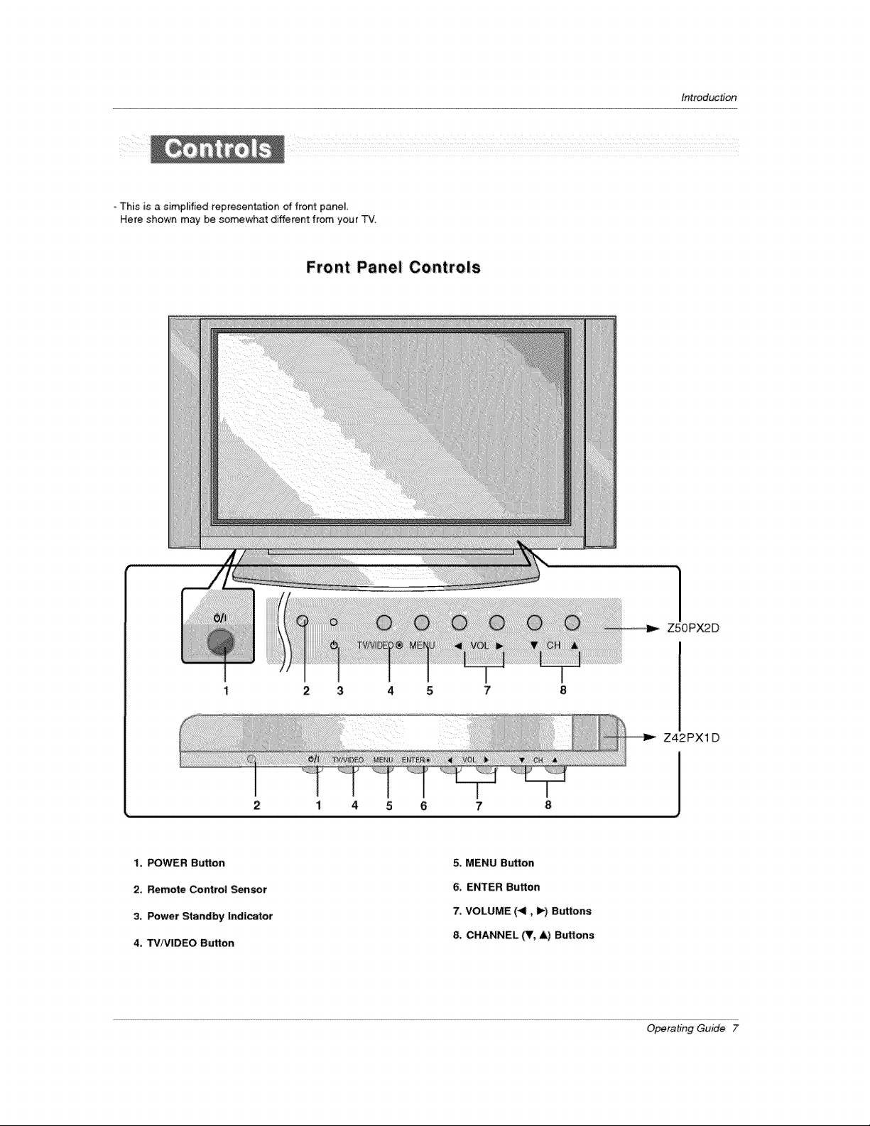
This is a simpFified representation of front pane].
Here shown may be somewhat different from your TV.
Front Panel; Controls
Introduction
1, POWER Button
2, Remote Control Sensor
3, Power Standby Indicator
4, TViViDEO Button
Z5OPX2D
2 3 4 5
Z42PX1D
2
i 4 5 6 7
5, MENU Button
6, ENTER Button
7, VOLUME (411,_) Buttons
8, CHANNEL (T, &) Buttons
Operating Guide 7
Page 8
Introduction
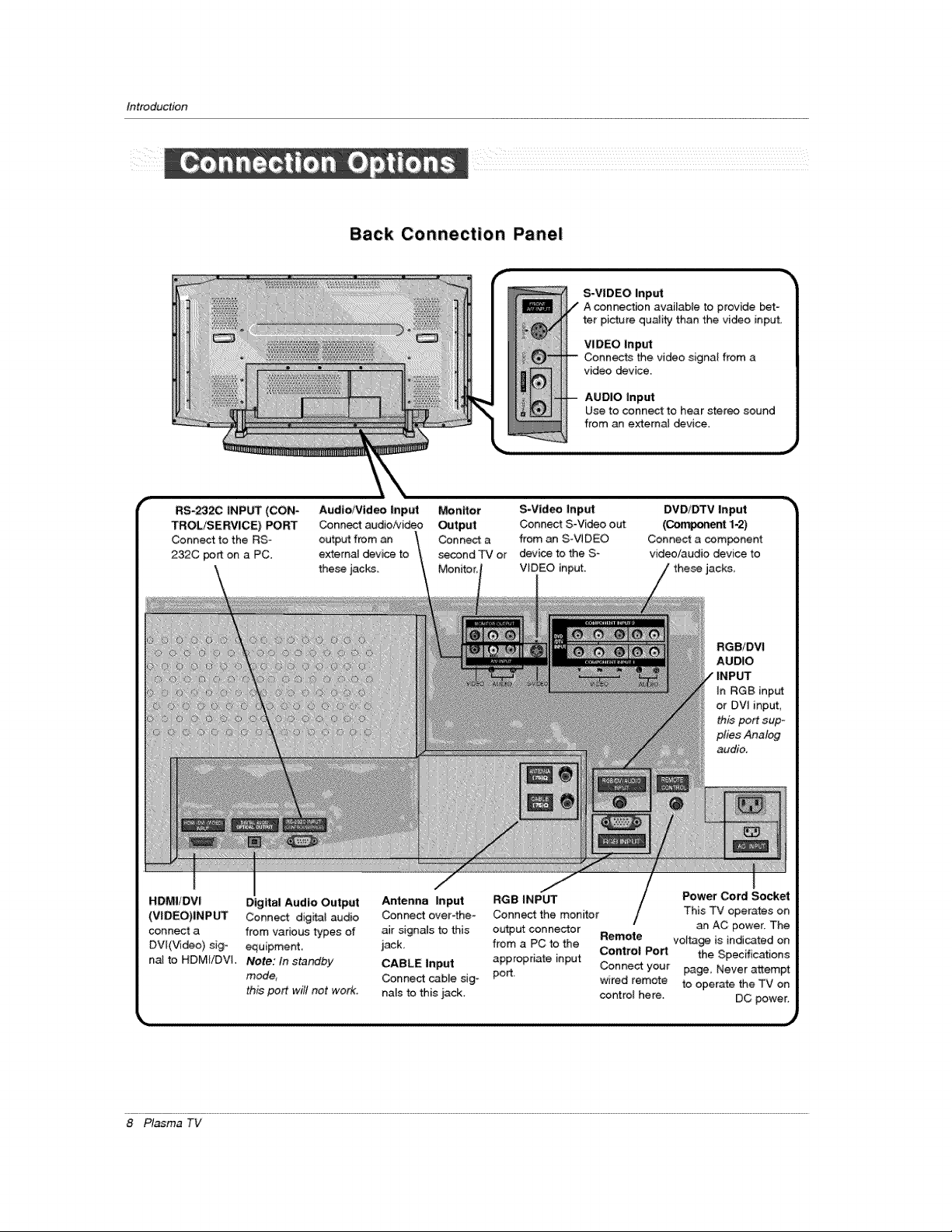
Back Connection Panel
S-VIDEO Input
VI DEC Input
Connects the video signal from a
video device,
AUDIO Input
Use to connect to hear stereo sound
from an external _vice,
RS-2320 INPUT (CON"
TROL_ERVICE) PORT
Connect to the RS-
232C port on a PC.
HDMI/DVI Digital Audio Output
(VIDEO)INP_ Connect dig_t audio
connect a from various types of
DV[(Video) sig- equipment.
na[ to HDMIiDVi. Note: In standby
mode,
this port will not work.
Audio/Video |nput Monitor
Conn_ audio/video Output
output from an Connect a
external device to second TV or
these jacks.
S-Vid_ Input
Connect S-Video out
from an S-VIDEO
devi_ to the S-
VIDEO input.
Antenna Input RGB INPUT Power Cord Socket
Connect over-the- Connect the monitor This TV operates on
air signals to this ou_ut connector Remote volta_ is indicated on
jack, from a PC to the Control Port the Specifications
CABLE input appropriate input Connect your page, Never attempt
Connect cabJe sig- port, wired remote to operate the TV on
na[s to this jack. control here. DC power.
DVD/DTV Input
(O-m_ent 1.2)
Connect a com_nent
video/audio device to
RGBIDVI
AUDIO
INPUT
In RGB input
or DVI input,
this port sup-
plies Analog
audio.
an AC power. The
8 P_sma TV
Page 9
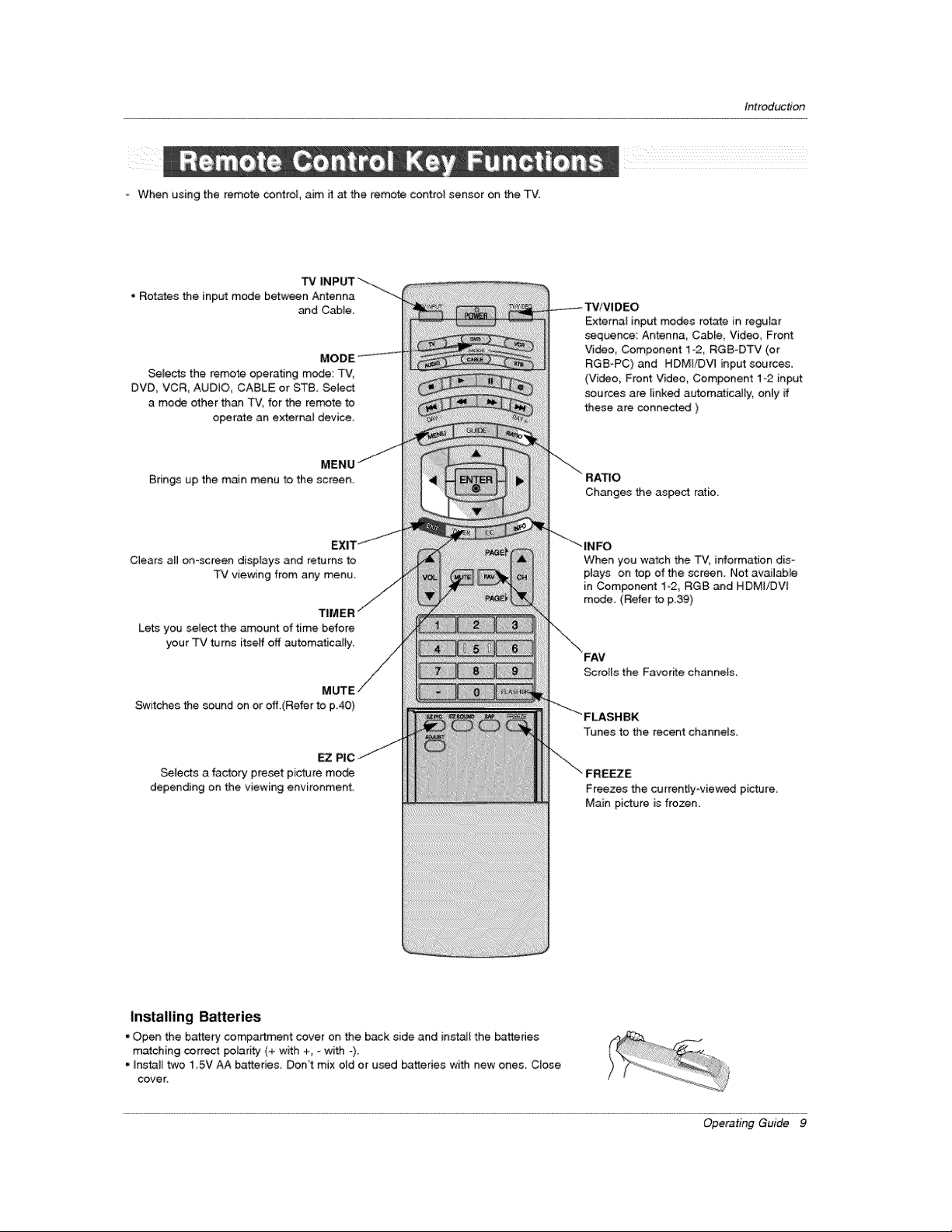
=When using the remote control, aim it at the remote control sensor on the TV.
TV
• Rotates the input mode between Antenna
_d Cable.
Selects the remote operating mode: TV,
DVD, VCR, AUDIO CABLE or ST8, _Iect
a mode other than TV, for the rem,3te to
operate an external device,
introduction
External input modes rotate in regular
sequence: Antenna_ CaMe, Video, Front
Video, Component 1-2, RGB-DTV (or
RGB-PC) and HDMI/DVl input sources,
(Video, Front Video, Component 1-2 input
sources are linked automatica[ly_ only ff
these are connected )
Brings up the main menu to the screen.
Clears aH on-screen displays and returns to
TV viewing from any menu,
Lets you select the amount of time before
your TV turns itseff off automatically,
Switches the sound on or eff.(Refer to p40)
EZ
Selects a factory preset picture mode
depending on the viewing environment.
RATIO
Changes the asset ratio.
When you watch the TV, information dis-
plays on top of the screen. Not available
in Component 1_2, RGB and HDMI/DVf
mode, (Refer to p39)
Scrolls the Favorffe channeis
Tunes to the recent channels
Freezes the currently-viewed picture
Main picture is frozen.
Installing Bakeries
• Open the battery compartment cover on the back side and install the batteries
matching correct polarity (+ w_th +_ =with _)
• Install two 1 5V AA batteries, Don't mix old or used ba_des with new ones, Close
cover_
Operating Guide 9
Page 10
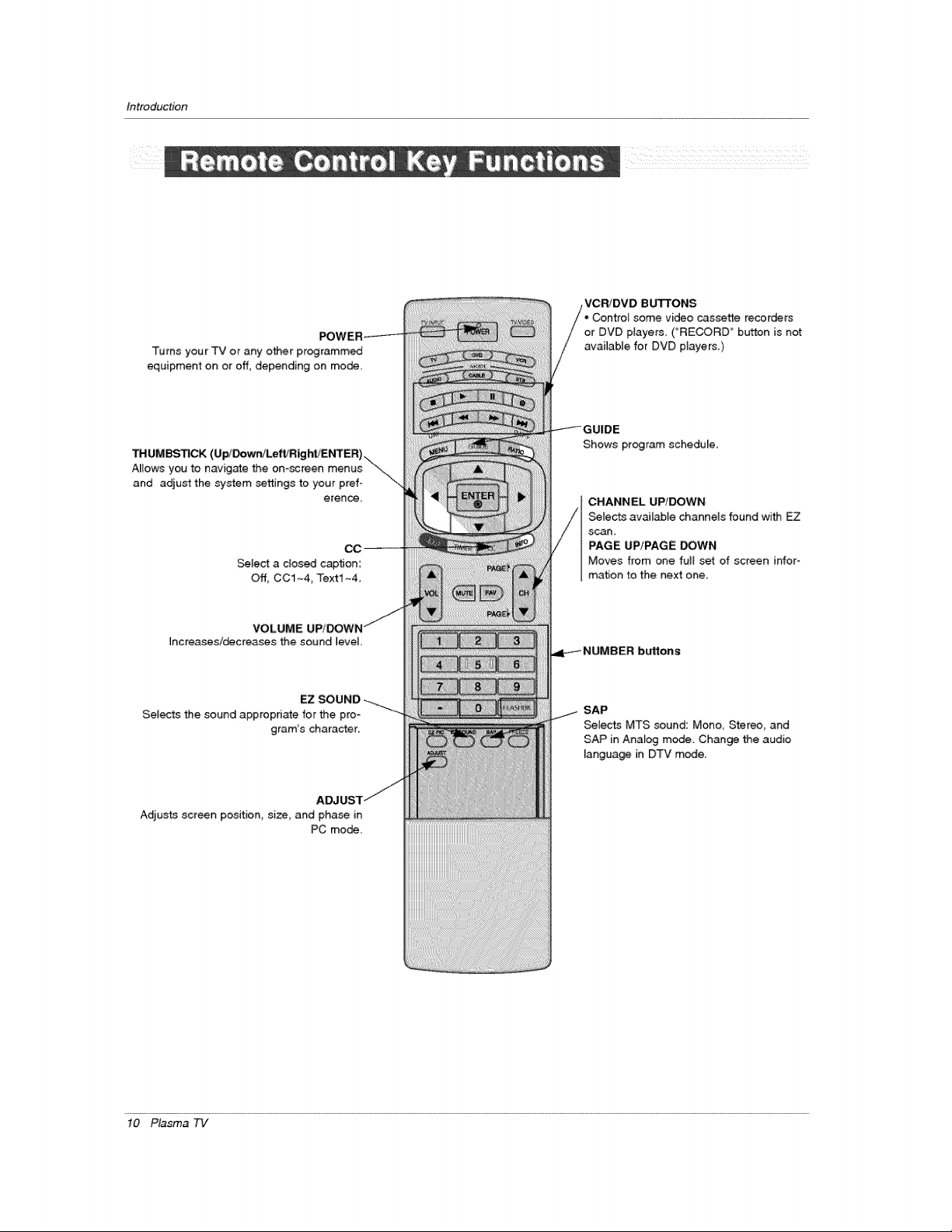
Introduction
Turns your TV or any other programmed
equipment on or off, depending on mode,
z z z z z z z z z z z z z z z z z z z z z_
VCRiDVD BUTTONS
Controi some video cassette recorders
or DVD players. ("'RECORD" button is not
awilable for DVD players.)
_UMBS_C'K
Mows you to navigate the on-screen menus
and adjust the system settings to your pref-
erence.
Select a c_osed caption:
Off, CC1~4_ Text1 ~4
Increasesi_creasos the sound Jevel.
Selects the sound appropriate for the pro-
gram's character..
Adjusts screen position, size_ and pha_ in
PC mode,
Shows program schedule.
CHANNEL UP/DOWN
Selects available channels found with EZ
scan,
PAGE UP!PAGE DOWN
Moves from one fult set of screen infor-
mation to the next one..
SAP
Selects MTS sound: Mono, Stereo, and
SAP in Analog mede. Change the audio
language in DTV mede.
10 Plasma 7q/
Page 11
Installation
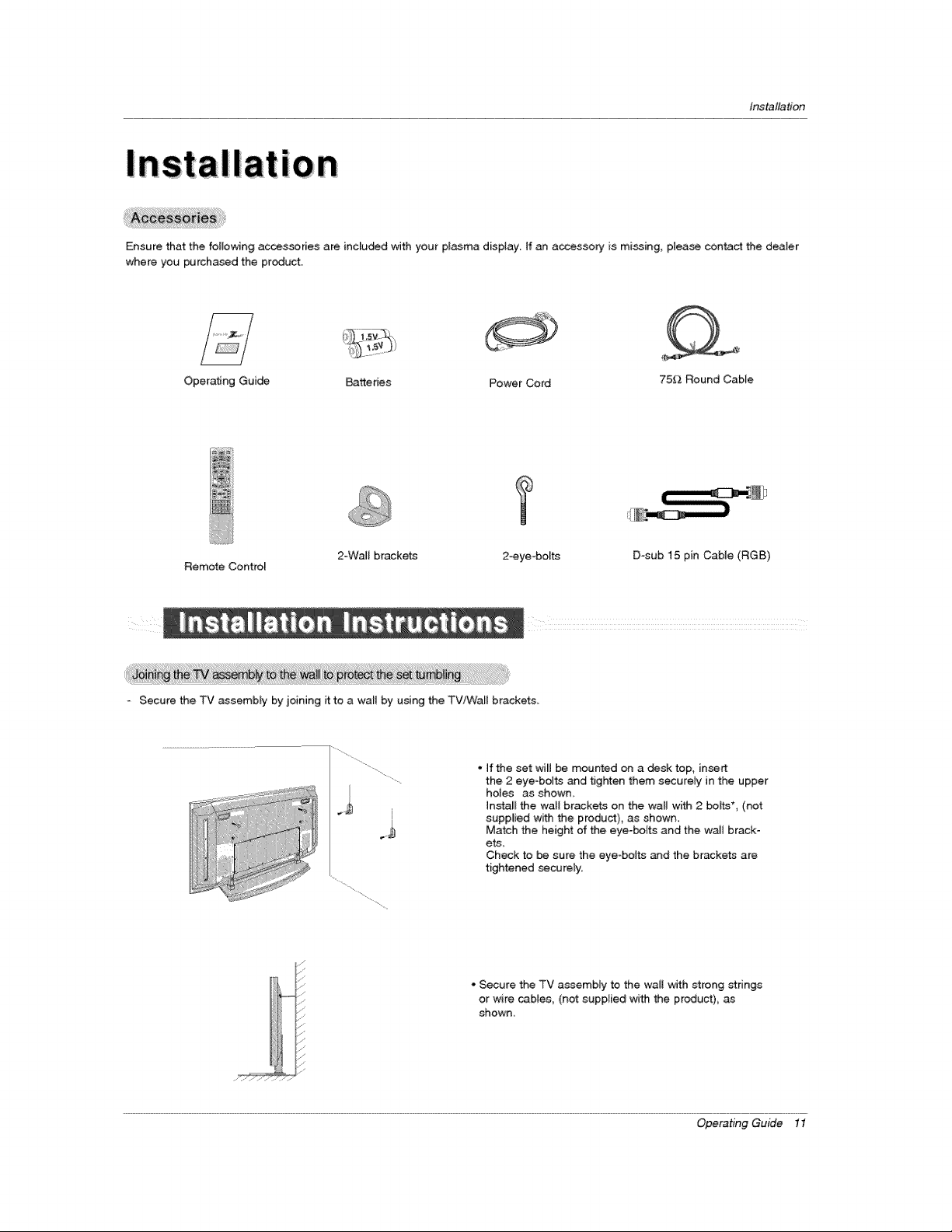
Ensure that the following accessories are included with your plasma display. If an accessory is mi_ing, please centact the dealer
when you purcha_d the product.
Operating Guide Batteries Power Cord 75_.-_Round Cable
T
Remote Control
* Secure the TV assembly by joining it to a wall by using the TV/Wall brackets,
2-WaJI brackets
ii).
2°eye -bo_ts D-sub 15 pin Cable (RGB)
, if the set wiB be mounted on a desk top, insert
the 2 eye-bolts and tighten them securely in the upper
holes as shown
Install the wall brackets on the wall with 2 bohts*, (not
supplied with the product), as shown.
Match the height of the eye-bolts and the waJt brack-
ets_
Check to be sure the eye bolts and the brackets are
tightened _curely.
• Secure the TV assembly to the waB with strong strings
or wire caMes, (not supplied with the product), as
shown,
Operating Guide 11
Page 12
Instatlation
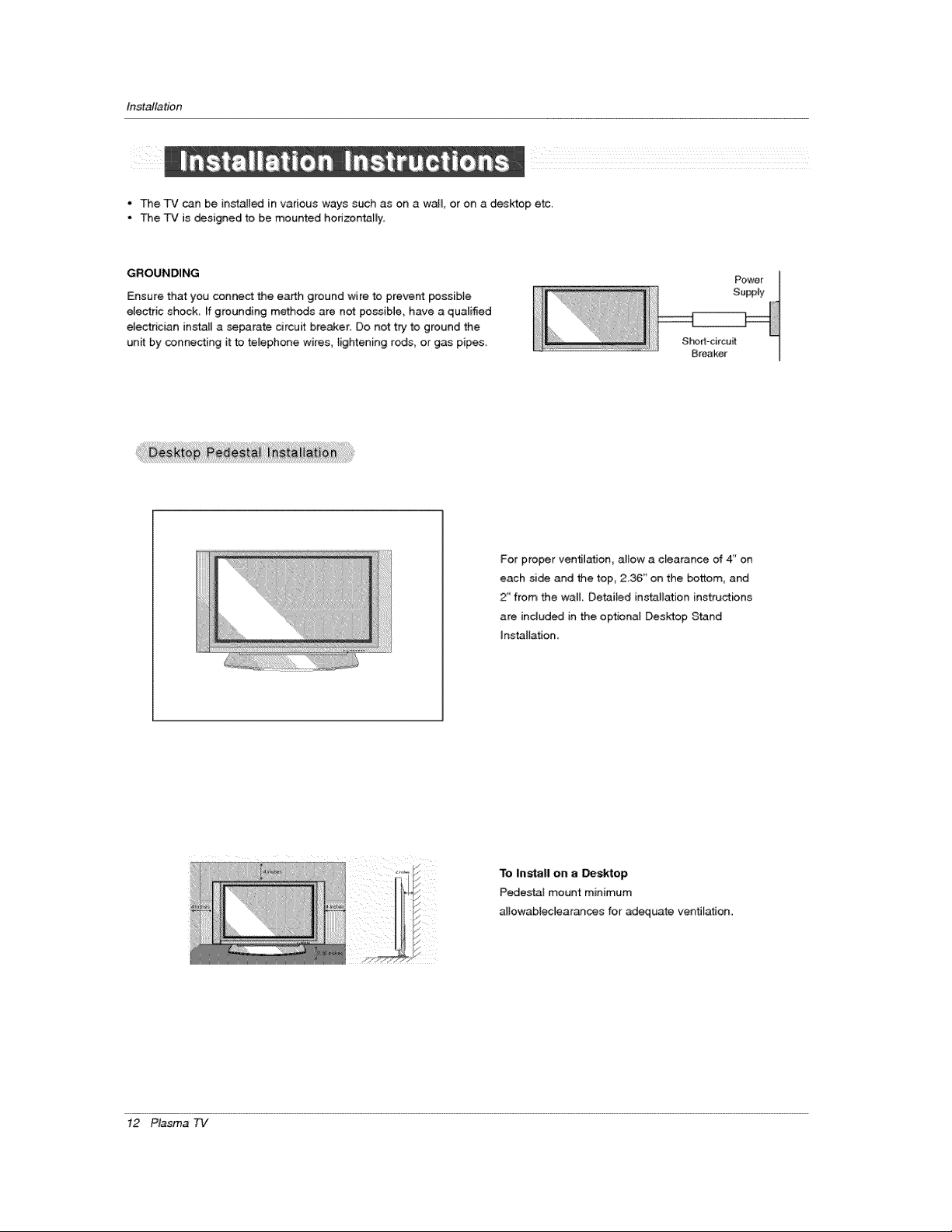
• The TV can be in_alted in various ways such as on a wall or on a desktop etc.
• The TV is designed to be mounted hodzontaiJy,
GROUNDING
Ensure that you connect the earth ground wire to prevent possible
electric shock If grounding methods are not possible, have a qualified
electrician install a separate circuit breaker, Do not try" to ground the
un_ by connecting it to teJephone wires, lightening rods, or gas pipes,
Short-circuit
Breaker
}For proper ventilation, ailow a ciearance of 4" on
each side and the top, 2.36 _ on the bottom, and
2" from the wa_l, Detai_ed installation instructions
are included in the optional Desktop Stand
installation.
To Install on a _sktop
Pedestal mount minimum
altowabiec]earan_s for adequate ventilation.
!2 Plasma 73/
Page 13
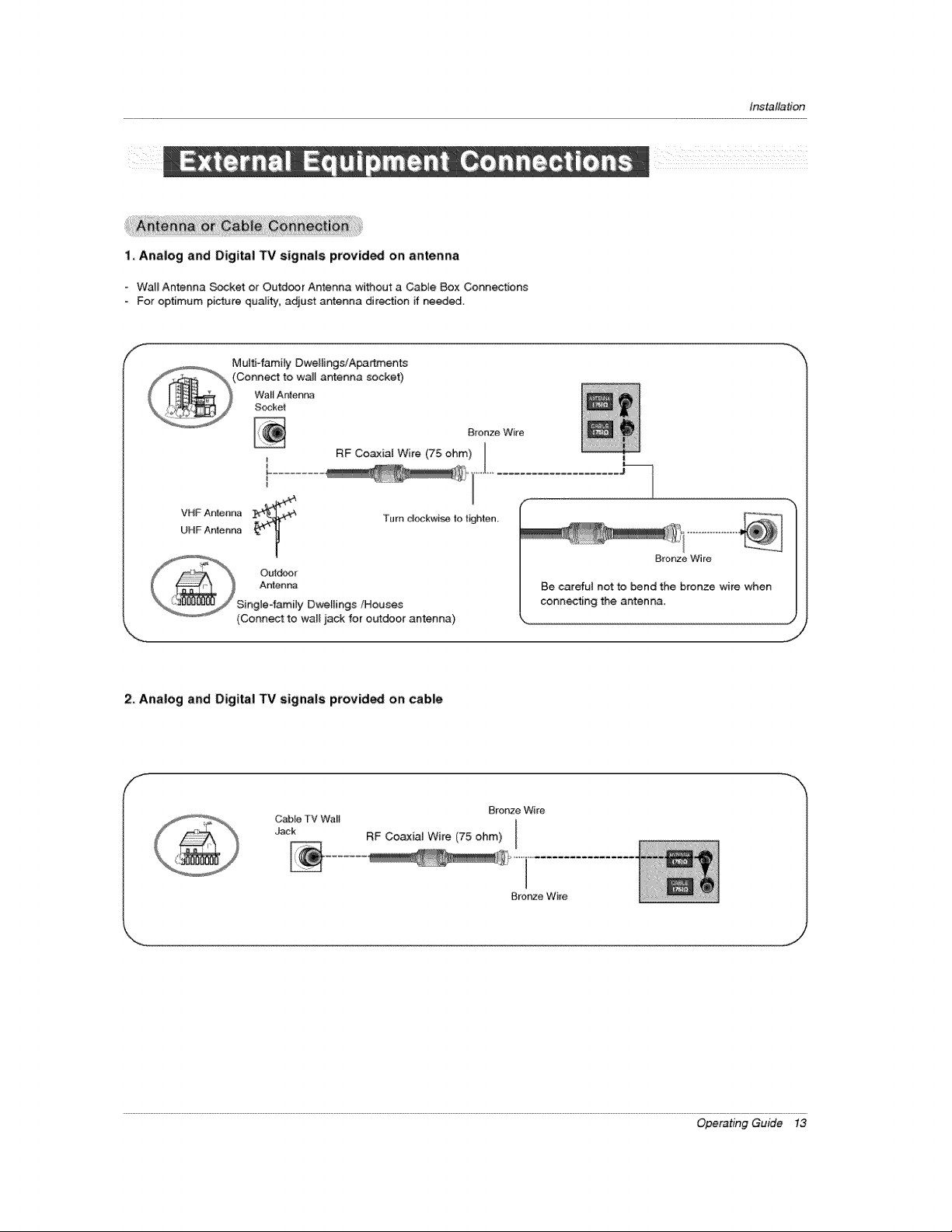
1, Analog and Digital TV signals provided on; antenna
- Watl Antenna _ket or Outd_r Antenna wi_out a Cable Box Connections
Fopoptimum picture quaJity, adjust antenna direction if needed.
ff_
Multi-fatality DweHings/Apartznen_
VHF Antenna
UHF Antenna
Outdoor
Antenr_a
Single-family Dwellings/Houses
(Conn_ to walE jack for outdoor antenna)
antenna socket)
Bronze Wire
RF Coa_xiat Wire (75 ohm) I
Turn clockwise to tkjhten_
Installation
Bronze Wire
Be carefut not to bend the bronze wire when
connecting the antenma,
,J
2, Analog and Digital TV signals provided on cable
Cable TV Wa_l
Jack RF Coaxial Wire (75 ohm)
Brortze V_ire
Operating Guide !3
Page 14
Installation
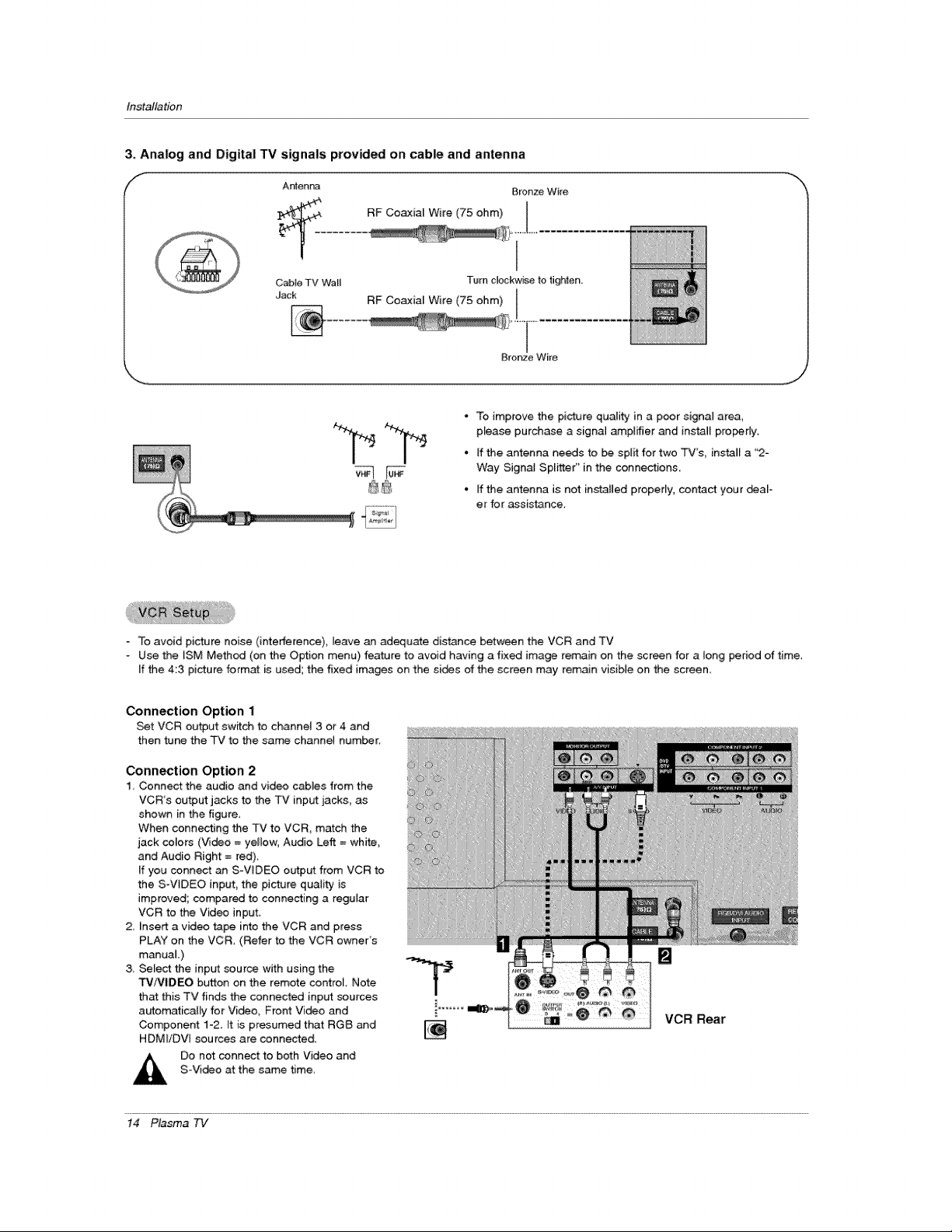
3, Analog and Digital TV signals provided on cable and antenna
f
RF Co_ial Wire (75 ohm)
CabFeTV Wall Turn clockw_e to tighten,
Jack RF Coaxial Wire (75 ohm)
Bronze Wire
- To improve the picture quaJity in a p_r signal area,
pEease purchase a signal amplifier and install pro_r[y.
• If the antenna needs to _ split for two TV's, ins_all a "2-
Way Signa_ Spritter" in the connections.
°ff the antenna is not installed properly, contact your _al-
et for assistance.
Bronze Wire
,i j
- To avoid picture noise (interference), leave an adequate distance between the VCR and TV
- Use the iSM Method (on the Option menu) feature to avoid having a fix_ image remain on the screen for a long period of time,
If the 4:3 picture format is used; the fixed images on the si_s of the screen may remain visible on the screen
Connection Option 1
Set VCR ou_ut switch to channel 3 or 4 and
then tune the TV to the same channel number
Connection Option 2
1, Connect the audio and video cables from the
VCR's output jacks to the TV input jacks, as
shown in the figure,
When connecting the TV to VCR, match the
jack colors (Video = yellow, Audio Left = white,
and Audio Right = red).
If you conn_ an S-ViDEO output from VCR to
the S-V_DEO input_ the picture quality is
improved; compared to connecting a regular
VCR to the Video input
2, Unsert a vid_ tape into the VCR and press
PLAY on the VCR, (Refer to the VCR owner's
manual )
& Select the input source with using the
TVNIDEO button on the remote control Note
that this TV finds the connected inpt,_ sources
automatically for Video, Front Video and
Component 1-2 it is presumed that RG8 and
H DM I/DVI sou rces are connected,
Do not connect to both Video and
S-V[_o at the same t_me
[]
VCR Rear
!4 Plasma 7q/
Page 15
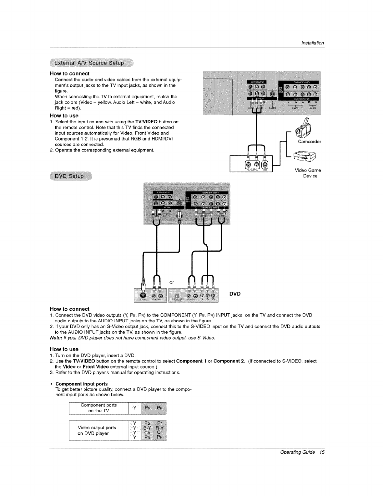
How to connect
Connect the audio and video cables from the externa] equip-
ment's output jacks to the TV input jacks, as shown in the
figure.
When connecting the TV to external equipment, match the
_ack colors (Video = yellow, Audio Left = white, and Audio
Right = red).
How to use
1. Select the input source with using the TVFVIDEO button on
the remote control. Note that this TV f[n_ the connected
inp_ sources automatically for Video, Front Video and
Component 1-2 it is presumed that RGB and HDMIiDW
sources are connected.
2. Operate the corresponding external equipment.
Installation
Camcorder
Video Game
Device
DVD
How to connect
1. Conned the DVD video outputs (Y, PEhPF_)to the COMPONENT (Y, P& PR) INPUT iacks on the TV _d connect the DVD
audio output_s to the AUDIO iNPUT jacks on the TV, as shown in the figure
2. ff your DVD only has an S-Vi_o output jack, conned this to the S-VIDEO input on the TV and conn_ the DVD audio outputs
to the AUDIO INPUT _acks on the TV, as shown in the figure.
Note." ff your DVD player does not have component video output, use S-Video.
HOW to u_
1, Turn on the DVD player, insert a DVD,
2_ Use the TMIVIDEO button on the remote control to select Component 1 or Com_nent 2 (ff connected to S_V_DEO, select
the Video or Front Video external input source,)
3 Refer to the DVD player's manual for operating instructions,
• Component |nput ports
To _t better picture quality, connect a DVD p_ayer to the com_-
nent input ports as shown below
Component ports
on the TV
Video output por_
on DVD player
Operating Guide 15
Page 16
Installation
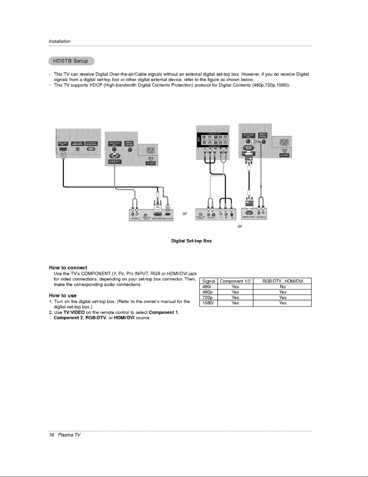
- This TV can receive Digital Over4he-aidC_le sign,s without an external digital set4op box. However, if you _ receive DigitaF
signals from a digffa_ set-top box or other digital external device, refer to the figure as shown below.
- This TV supports HDCP (High-bandwi_h Digital Contents Protection) protocol for Digital Contents (480p,720p, i080i).
Or
Digital Set4op Box
How to conn_t
Use the TV's COMPONENT (Y, P& PR) iNPUT, RG8 or HDMI/DVI jack
for video connections, depending on your set4op box connector. Then,
make the corresponding audio connections.
How to use
1. Turn on the digital set4op box, (Refer to the owner's manua_ for the
digi_l set-top box.)
2. Use TV/VlDEO on the remote control to _]ect Compenent 1,
Component 2, RGB-DTV, or HDMIiDVl source.
or
Si_[nal Component 1t2 RGB-D_, HDM_VI
480i Yes No
480 P Yes Yes
720p Yes Yes
1080i Yes Yes
!6 Plasma 7q/
Page 17
Installation
This TV provk:_es P_ug and Play capability; meaning that the PC adjusts automatically to the TV's settings
= The TV perceives 640x480 60Hz as DTV 480p based on the PC graphic card, change the screen scanning rate for the graphic
card accordingly
<When the PC supports DVI>
How to connect
1. Connect the PC to HDM]iDV[ port of this TV with an HDMI-to-DVi cable(not supplied with this product).
2 if the PC(or the sound card of the PC) has an analog audio output connector, connect the PC's audio output to RGBiDV[
AUDIO iNPUT port located on the upper side of RGB INPUT port.
How To Use
1 To get the best picture qua[i#y, adjust the PC graphics card to 1024x768, 80Hz.
2. Setect HDMIIDW input source in input source option of SETUP menu.(Refer to P.25)
TV!V|DEO button is a_so avail_le for this purpose.
3. Check the image on your TV. There may be noise assod_ed with the resolut:ion, ve_ca_ pattern, contrast or brightness in PC
mode. ff noise is pre_nt, change the PC output to another resel_ion, change the refresh rate to another rate or adiust the
brightness and contrast on the VIDEO menu until the picture is clear, if the refresh rate of the PC graphic card can not be
changed, change the PC graphic card or consult the manufacturer of the PC graphic card.
<When the PC supports RGB>
How to connect
1 Connect the PC to RGB iNPUT port of this TV with a RGB cab_e(not supplied with this product)_
2 ff the PC(or the seund card of the PC) has an analog audio ou_ut connector, connect the PC's audio output to RGBiDVI
AUDIO iNPUT port _ocated on the upper si_ of RGB LNPUT port,
How To Use
1_ To get the best picture quality, adjust the PC graphics card to 1024x768_ 60 Hz
2 Select RGB-PC input source in input source option of SETUP menu (Refer to P,25)
Once you select RGB-PC in main input option of SETUP menu_ TV/VIDEO button is aJso available for this purpese_
3, Check the image on your TV. There may be noise associ_ed wffh the resolution, ve_ca_ pattem_ contrast or brightness in PC
mode_ if noise is present change the PC ou_ut to another reselution_ change the refresh rate to another rate or adjust the
brightness and contrast on the VIDEO menu until the picture is clear, if the refresh rate of the PC graphic card c_ not be
changed, change the PC graphic card or consuit the manufacturer of the PC graphic card.
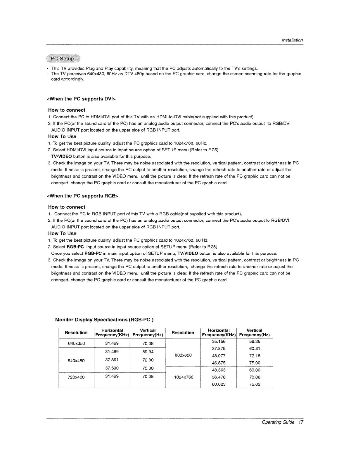
Monitor Display Specifications (RGB-PC)
Resolution Frequency(KHz) Frequency(Hz) Resolution Frequency(KHz) Frequency(Hz)
640X350 31.469 70,08
640x480 37,861 72,80
720x4_ 31.469 70,08
Hottzo ntal Vertical Horizo ntal Vertical
35.156
31,469 59.94
37.500 75,00
800x600
1024x768
37.879
4&077
46,875
48,363
56_476
60_023
5&25
60.31
72,18
7&O0
60_00
7&06
75,02
Operating Guide 17
Page 18
installation
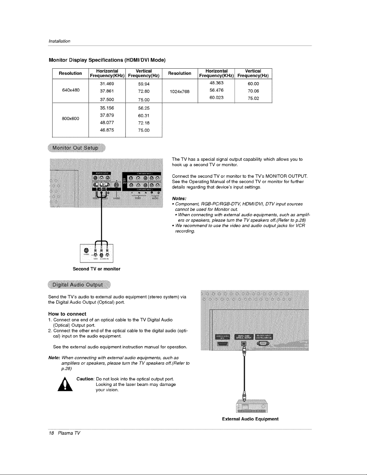
Monitor Display Specifications (HDMIIDVI Mode)
Resolution Frequenccy(KHz) Frequency(Hz) Resolution Fteguency(KHz) Frequency(Hz)
640x480 1024x768 56,476 70_06
800x600
Horizontal Vertical Hotlzon_l Vertical
31,469
37,861
37._0
35,156
37.879
48.077
46,875
5&94
72,80
75.00
56.25
60.31
72.18
75,00
The TV has a special signa_ output capability which allows you to
hook up a second TV or monitor.
Connect the second TV or monitor to the TV's MONITOR OUTPUT.
See the Operating M_ual of the second TV or monitor for fu_er
details regarding that _vice's input settings.
Notes:
. Component, RGB-PC/RGB-DTV, HDMt/DVI, DTV input sources
cannot be used for Monitor out,
• When connecting with external audio equipments, such as amp#l-
ets or speakers, please turn the TV speakers off.(Refer to p_28)
. We recommend to use the _4deo and audio output jacks for VCR
recording.
4&363 60,00
60023 7&02
_cond TV or monitor
Send the TV's audio to external audio equipment (stereo system) via
the Digita_ Audio Ou_ut (Optical) port.
How to connect
1 Connect one end of an optical cable to the TV Digital Audio
(Optical) Output port
2, Connect the other end of the optical cable to the digital audio (opti-
_J) input on the audio equipment.
See the external audio equipment instruction manual for operation
Note: When connecting with external audio equipments, such as
amptifers or speakers, please turn the TV speakers off,(Refer to
p.28)
Caution: Do not look into the optical output port,
Looking atthe I_er _am may dama_
your vision.
18 Plasma TV
iiiiiii/:>;i;iii
Ji
_ii:ii_i,iiii'i'i_
External Aadio Equipment
Page 19

Installation
HIGN _%Nrl-_ON MULTIMF=D_ INTE2RFNDE
- HDMV", the HDMm logo and High-Definition Multimedia Interface is a trademark or registered trademark of HDM_ Licensing."
This TV can receive the High-Definition Multimedia _nterface(HDMI) or the Digi_l Visual lnterface(DVl).
- This TV supports HDCP(Nigh bandwidth Digital Contents Protection) Protocol for 72Ox480p, 128Ox720p, and 192Ox1080i resolu-
tion.
° When you connect thisTV with a source device(DVD player,Se_ Top Box or PC) supporting Auto HDM_/DVl function,the output
resolution of the source device will be automatically set to 1280x720p.
If the source device does net support Auto HDMI/DVl, you need to set the output resolution appropriately.
To get the best picture quality; adjust the DVD P_ayer or Set Top Boxs output resolution to 1280x720p and the PC graphics card's
output resolution to 1024x768, 60Hz.
o If the source device has an HDMI output, no other audio connection is necessary because HDMI-to-HDMI connection includes
both video and audio.
- If the source device has a DVl output and no HDMI output, a separated audio connection is necessary,
<When the sour_ device(DVD player or Set Top Box) supports HDMI>
How To Connect
1. Connect the source device to HDMI/DVI port of this TV with an HDM_ cable(not supplied with this product).
2, No separated audio connection is necessary.
How To Use
If the sou rce device supports Auto HDMI function_ the output resolution of the source device wil_ be automatically set to 1280x720p,
If the source device does not support Auto HDML you need to set the output resolution appropriately,
To get the best picture quality, adiust the output resolution of the source device to 1280x720F
Select HDMI/DVI input source in input source option of SETUP menu(Refer to P25)
TV/VIDEO button is also available for this purpose
<When the source device(DVD player or Set Top Box) supports DVI>
How To Connect
I, Connect the source device to HDMI/DVl port of this TV wi_ a HDMFto_DVt cable(not suppiied with this product),
2_ A separated audio connection is nece_ary:
& If the source device has an analog audio output connector, connect the PC's audio output to RGBiDVt AUDIO INPUT port Iocet -
ed on the upper side of RG8 INPUT _rt
How To Use
ff the source devise supports Auto DVl function the output resok,_tion of the source device will be automatically set to 1280x720p.
- Ifthe source device does not support Auto DVl you need to set the output resolution appropriately:
To get the best picture quality, adiust the output resolution of the source device to 1280x720p.
o Select HDMI/DVl input source in input source option of SETUP menu.(Refer to P.25)
TV/V|DEO button is also avail_le for this purpose.
Operating Guide 19
Page 20

Installation
Cable sample
f
(not supplied with the product)
HDMI Cable
HDMI to DVl Cable
(not supplied with the product)
Fiber Optic Digital Audio Cable
(not supplied with the product)
Analog Audio Cable(RCA type)
(not supplied with the product)
Analog Audio Cable(Stereo to RCA type)
(not supplied with the product)
20 Plasma TV
,,J
Page 21

Installation
How to use
1. Connect the HDMItDV_ Source Devices(DVD Player or Set Top 8ox or PC) and the TV SET.
2. Turn on the display by precsing the POWER bL_on on the TV SET and HDML/DVl Source Devices remote control.
3. _t_ HDMI/DVl hput source in input source option of SETUP menu.(Refer to P.25)
4. Che_ the image on your TV SET. There may be noise associated with the resolution, vertical pattern, contrast or brightness in
HDM}/DVi Source Devices. ff noise is present, change the HDMI/DVt Source Devices to another resolution, change the refresh
rate or adjust the brightness and contrast on the menu unti_ the picture is clear. If the refresh rate of the PC graphics card can
not changed, change the PC graphics c_ard or consuJt the _nufacturer of the PC graphics card.
Notes:
- Depending on the graphics car_ DOS mode maynot work ffyou use a HDMI to DVI Cable.
- Avoid keeping a fixed image on the TV SET screen for a long period of time. The fixed image may _come permanently imprint-
ed on the screen. Use the Orbiter screen saver when possible.
- When Source Devices connected HDMI/DVt input, output PC Reso/ution(VGA, SVGA, XGA), Position, Size may not fit to
Screen. As shown the lower picture, press the ADJUST button to adjust the screen Position of TV SET and contact an PC
graphics card service center.
- When Source Devices connected HDMI/DVI input output TV SET Resolution(480p, 720p, 1080i)_ TV SET D[splay fit EIA/CEA-
861°B Specification to Screen. tf not, refer to the Manual of HDMI/DVI Source Devices or contact your service center.
- In case HDMI/DVI Source Devices is not connected Cable or _or cable connection, "NO SIGNAL '_OSD display in HDMI/DW
Input. And in case of, Video Resolution not supported TV SET output in HDM//DVI Source Devices, "IIVVALID FORMAT" OSD
display. Refer to the Manual of HDMI/DVI Source Devices or contact your service center.
PC mode
In This Mode, the Supported TV SET Resolution Specification
- 1920 x 1080 I @ 59.94Hz t 60Hz, 16:9
1280 x 720 P @ 59_94Hz / 60Hz, 16:9(preferred format)
- 720 x 480 P @ 59 94Hz / 60Hz, 16:9
- 720 x 480 P @ 5g 94Hz / 60Hz, 4:3
in This Mode, the Supported PC Resolution Specification
640 x 480 @ 60Hz
- 640 x 480 @ 72Hz
- 640 x 480 @ 75Hz
800 x 600 @ 56Hz
- 800 x 600 @ 60Hz
- 800 x 600 @ 72Hz
- 800 x 600 @ 75Hz
- 1024 x 768 @ 60Hz(preferred format)
1024 x 768 @ 70Hz
- 1024 x 768 @ 75Hz
Operating Guide 21
Page 22

Operation
* in this manual, the OSD (On Screen Display) may _ different from your "P¢'s _use it is just an
example to help you with the TV operation,
First, connect power cord correctly At this moment, the TV swffches to standby mode.
tn _andby mode to turn TV on, press the 0/I, TViVIDEO ,_ CH (& /V) button on the TV or press the POWER,
TM INPUT, TVNIDEO, OH (& / V), Number (0 ~ 9) button on the remote control.
2. Select the viewing source by using TViVIDEO button on the remote control
This TV is programmed to remember which power state it was _ast set to, even if the power cord is out.
3. When finished using the TVI press the POWER button on the remote control The TV reverts to standby mode.
TV Setup
- The menus _n _ shown on the screen in the selected language First select your langua_
1. Press the MENU button and then use & / V button to select the OFfI[ON
menu
2. Press the I_ button and then use A / V bb_on to se_ed Language.
3. Pre_ the I_ button and then use A / Y b_,_tan to select your _sired language.
From this point on, the on-screen rr_nus wilt be shown in the setected lan-
guage.
4_ Pre_ EXiT button to return to TV viewing or press MENU button to return to
the previous menu.
22 Plasma 7q/
Page 23

Autorr_3ticaliy finds all available channels through antenna or cable inputs, and stores them in memory on the channe_ list.
- Run EZ Scan again after my Antenna/Cable connection changes.
- A password is required to gain access to EZ Scan menu ff the L_k System is turned on.
1 Press the MENU button and then use & _V button to select the S_'I'_,_3Pmenu.
2. Press the I_ button and then use A IY button to select _S,'_
3. Press the ENTER button to _gin the channel search.
Allow EZ Scan to complete the channel search cycle for ANTENNA, and CABLE.
Operation
- A password is required to gain access to ManuaJ Scan menu if the Lock System [s turned on.
1 Press the MENU button and then use & !V button to select the _31P menu.
2, Press the II_ button and then use 4, IV button to select I_1[_ _,
3. Press the I_ button and then use & x V button to select TV, DTV, CAT'v, _d
CADTV.
4. Press the _ button and then use A / V button to select channel number you
want to add or delete,
5. Press the ENTER button to add or delete for the channel num_r.
6. Press EXIT button to return to TV viewing or press MENU button to return to
the previous menu.
Notes:
• This channel number is a physical channel number, which is different from the normal channel number shown in Channel
Edit.
• T'_" analog antenna(over-the-air) TVsignal
DTV: d_gital antenna(over-the-air) TV signal
CATV: analog cable TV signal
CADTV: digital cable TV signal
Operating Guide 23
Page 24

Operation
- There are two different ways in order to add or delete scanned channels. One
is °Custom List" _d the other is °Favorite List _ in the channel list. Both of them
are available after _ on the _UJP menu.
A Custom List can be created by toggling each channel on or off with ENTER
button The channels in the Custom List are displayed in bfack color, and the
channets deleted from the Custom List are displayed in gray color. Once a
channet is highFighted you can add or delete the channel by referring to the
sm.3_ win_w at the topqeft corner of the screen ?fou can create your own
Favorite LisL Use the FAV b_ton on the remote control when a channel is
highlighted and then you can add or de_ete the channel toffrom the Favorite
List
1 Press the MENU button and then use A ,'V button to select the _rl'_ menu,
2 Press the I_ button and then use A/V button to select Chear-_! Edit
& Pre_ the !_ buttom You wilt now see a screen fi]_ed with channel numbers and
a preview picture
4. Use & /V _11 zI_ button to select a channel _d then use the ENTER button to
add or delete it. Press FAV button to add the channe_ to the Favorite List.
5, Press EXiT button to return to TV viewing or press MENU button to return to the
previous menu,
- It indic_es stren_ of the DTV signal whether you need to adju_ your antenna or digital cable inp_.
The higher the signal strength, the less likely you are to expedence picture _gradation.
- DTV Signal: Only when the input signa_ is DTV or CADTV, this function is available.
1. Press the MENU button and then use A ,,V button to select the _ menu.
2. Press the I_ button and then use A/V b_'ton to select _ Slgne_L
3. View the on-screen signal strength monitor to see the qualib/of the signal being
received.
4_ Press EXIT button to return to TV viewing or press MENU button to return to the
previous menu,
24 Plasma 7q,/
Page 25

- Cheo_ preset [abels for your channels.
- If a channel label is provided on the signal from the broadcasting station, the TV displays a short n_e for a channel -
even if you didn't preset a label for the channel.
1. Press the MENU button and then use ,i, JV button to select the _JP menu.
2. Press the I_ button and then use & _y button to selec_ Cl-_ L4zbe].
3. Pre_ the I_ button. You will now see a screen filled with Labels and a preview screen.
4. Use the OH Az_ button to sele_ a channel to Label.
5, U_ A / V t41 t i_ button to select the appropriate label for the channel then press ENTER button to set the Label to
the selected channel
- if you press ENTER button in TV viewing mode, you will see the channel banner. • For example:
Operation
Change the picture source so you can watch your TV, _ble T,J, VCR, DVD, or any other devices that are connected to your TV.
1. Press the MENU b_,_tton and then use A _V button to select the _f_P menu.
2. Press the I_ button and then use A/V button to select _put Source.
3. Press the I_ button and then use A t V button to setect the source'. Antenna_
Cable _deo, Front Videe_ Componentl_ Com_nent2, RGB-DTV (or RGB-PC),
HDMJiDW,
4. Press EXIT button to return to TV viewing or press MENU button to return to the
previous menu.
Note:
• To toggle RGB-DTV and RGB-PC, select RGB-DTV(or RGB-PC) and press ID.
button.
Sets a Jabel to each input source or lets you skip the input source which is not
in use when you press TV/VlIDEO button.
1_ Press the MENU button and then use A / V button to select the S_'Ff_ menu.
2. Press the i_ button and then use A _1, button to select _t _tbel.
3. Press the I_ button and then use & fV button to select the _urce: Vi_o Front
Video, Component1, Component2, RGB, HDMIiDW.
4. Press the _1 /I_ button to select the tabeL
5, Press EXIT button to return to TV viewing or press MENU button to return to the
previous menu.
Operating Guide 25
Page 26

OF,;_ratien
EZ Picture adjusts the TV for the best picture appearance, Select the preset value in the EZ Picture menu based on the
program category:
o When ad)usting Vi_o menu options (contrast, bdghthess, color sharpness_ tint, and color temperature) manually, EZ
Picture automatically changes to Custom.
- D_lght_ No_al, Night T_, Movie_ Video Game and Spor_ settings are preset for optimum picture qua_iby at
the factor/and are not adjustable.
1. Press the _ PIC button repeatedly to select the picture appearance setup optJon as shown below:
C_tom (your own settings), Day_Jght, Normal, Night Time, Movie, Video G_e, and Sports.
• You can aJso use the VIDEO menu to adju_ EZ Picture.
2. Press the F__IT button to save and return to TV viewing or press MENU button to return to the previous menu.
Adju_ the picture appearance to suit your preference and viewing situ_ions.
1. Press the MENU button and then use A/V b_ton to select the VIDEO menu,
2, Press the II_ button and then use A/V button to select the _sired picture option
(Contrast, Bttghtness, Color, Sharpness, or TLnt ).
3. Press the I_ button _d then use _1 / I_ b_on to make appropriate adjustrr_nts.
4. Press EXIT button to return to TV viewing or press MENU button to return to the
previous menu.
- Choose one of three automatic color adjustments Set to warm to enhance hotter
colors such as red, or set to coot to see tess intense co{ors with more biue.
1. Press the MENU button and then use A/Y button to select the VIDEO menu.
2. Press the I_ button and then use A/V button to select Color Temperal,.,ure.
3. Press the I1_ button and then use ,i, ,_V button to select either Cool, Medium or
WC_Tn,
4. Press EXIT btYtton to return to TV viewing or press MENU button to return to the
pravious menu.
Use to quickly reset all the _deo menu options to their original factory preset
Values,
1. Press the MENU button and then use &/V button to select the V_BEO menu.
2, Press the I_ button and then use A /V button to select Video Res4_t,
3_ Press the II_ button to reset the Video menu options to originaJ v_ues,
26 Plasma 7q,/
Page 27

Other ranguages may be available ff a digP_J signal is provi_d by the broad-
casting station.
1, Press the MENU bb_ton and then use & / V bt_ton to seiect the AUDIO menu_
2_ Press the I_ button and then use A tY button to select Audio language.
3, Press the lip button and then use & _V button to setect: English, Spanish, or
French.
4. Press EXIT button to return to TV viewing or press MENU button to return to the
previous menu.
- _ans for changes in sound levei during commerc;als, then adjusts the sound
to match the specified audio level EZ SoundRite makes sure that the volume
leve_ remains consistent whether you are watching a commercia_ or a regular
TV program
1. Press the MENU bL,_ton and then use A ,'Y button to select the AUDIO menu.
2. Press the i_ button and then use A/V button to setect EZ SoundJ_te,
& Press the I_ button and then use & / V button to setect On or Off
4. Press EXIT button to return to TV viewing or press MENU button to return to the
previous menu.
Operation
EZ Sound lets you enjoy the best sound without any special adjust_nt becau_ the TV sets the appropriate sound
op_ons based on the program content.
When adjuring sound options (treble, bass, and front surround) manually, EZ Sound automatically switches to Custom.
N0rmal, Stadium_ News Music_ and Theater are preset for g_d sound quat_bt at the factory and are not adjustable.
1. Press the EZ SOUND button repeatedly to _lect the appropriate sound setup as shown be_ow:
Custom (your own settings), Normal, Stadium, News, Music, and Theater.
. You can _so adjust EZ Sound in the A_IO menu.
2. Press EXIT button to save and return to TV viewing or press MENU button to return to the previous
menu.
Adjust the sound to suit your taste and room situations
1. Press the MENU bt,_on and then use A / V button to seled the AUDIO menu.
2. Press thel_ button and then use & ,,V b_ton to select the desired sound option
(Balance_ Treble, or _)_
3. Press the I_ burn and then use _ / I_ button to make appropnate adjustrr_ents_
4 Press EXIT button to return to TV viewing or press MENU butch to return to the
previous menu,
Operating Guide 27
Page 28

Operation
$R$(0) is a trademark of SRS Labs, inc.
TruSurround XT technology is incorporated under _icense from SRS Labs, tnc,
Manufac_red under license from Do_by Laboratories, "Doiby" and the _uble-D symbol are trademarks of Dolby Laboratories,
1, Press the MENU button and then use A/V button to select the AUDIO menu,
2. Press the I_ button and then use A/V button to select hont SurtaX,
3. Press the I_ button and then use A tV burn to select Off, 3D _So_d
System or SRS (Sound Retrieval System) _Surround XT,,
- 31) Ec._oSound System
Creates a stunning simulated stereo effects from any mone sound and a
realistic three-dimensiena_ sound with a very wide and deep sound stage
into stereo sound.
* _ TTuSurround
Takes advantage of any mu_ti-channel format without needing to add extra
s_akers or equipment. Dialog c_arky, bass enrich_nt, and the addition of
stereo audio enhancement that produces an immersive sound experience
from standard stereo material
4. Press BIT button to return to TV viewing or press MENU button to return to
the previous menu,
o Turn TV speakers off if using extemai audio equipment. Feature turns the TV
Speakers option On or Off_
1. Press the MENU bL.C_tonand then use A iV button to sel_ the AUDIO menu,
2. Press the I_ button and then use A iV button to select TV S_er,
3. Press the 1_ button and then use A _V button to seJect On or Off.
4. Press EXIT button to return to TV viewing or press MENU button to return to the
previous menu.
28 Plasma 73/
Page 29

BBE High Definition Sound restores cladty and presence for better speech
inteBigibility _d music realism.
1. Press the MENU button _d then use A/V button to select the &tfl_[O menu.
2. Press the I1_ button and then use A/V button to select E_E.
3. Press the _ button and then use & / V button to select On or Off.
4. Press EXIT button to return to TV viewing or press MENU button to return to
the previous menu.
• _ Manufactured un_r license from BBE Sound, tnc,
•Trebie, Bass or BBE aren't suitable for SP,.ST$_ mode.
Operation
This TV can receive MTS stereo prograrr_ and any SAP (Secondary Audio Program) that accompanies the stereo program;
if the station transmits an addkionat sound signal as wetl as the original one
- When having selected Stereo or SAP button on the remote control, this TV can only receive the signal when the TV station
transmffs the proper signals.
- Mono sound is automatically re_ived if the broa_ast is only in Mono; even though Ster_ or SAP has been selected.
- Select Mono if you want to listen to mono sound during stereo/SAP broa_aeting
Stereo or SAP can be received in a Analog channel
1 Use the SAP button to select your desired MTS mode in a analog signal Each time you press the SAP button, Mo_o,
Stereo or SAP appear in turn
• ff other languages are avaitab_e on the digital signal, select them with the SAP button.
2. Press EX_ button to save and return to TV viewing.
Operating Guide 29
Page 30

OF;_rafion
The time is set automatically from a digitaJ channe_ signal,
The digital channel signa] includes information for the current time provided by the broadcasting sta_on,
Set the ctack _nuai_y, if the current time is set incorrectly by the auto clock function.
1. Press the MENU button _d then use &/_' button to select the TD_I[E menu.
2. Press the I_ button and then use A/V button to setect Aulo Clock.
3, Pre_ the I_ button and then use A/V button to so}oct _or_.
4 Press the I1_button and then use A _V button to select your viewing area t_me
zone: Eastern, Central, Mountain, Pacific, Al_ka, or Hawaii.
5. Press EX|T button to return to TV viewing or press MENU button to return to
the previous menu.
If current time setting is wrong, reset the dock manuai}y.
1. Press the MENU button and then use A/V button to select the T_£ menu.
2. Press the I_ button and then use A /V button to select M_rlualClo_
3. Press the I_ button and then use _1 / I_ button to select either the year, date,
or time optJon_ Once selected, use the & _V button to set the year, date, and
time op_ons,
4, Pre_ EXIT button to return to _ viewing or press MENU button to return to
the previous menu.
- Timer function operates onty if the current time has been set
- OffQqn-er function overrides On-qqmer function if they are both set to the same time
The -iV must be in standby mode for the On-qqrr_r to work.
- ff you do not press any button wffhin 2 hours after the TV turns on with the On Timer function, the TV _[[ automatically revert to
standby mode,
1. Press the MENU button _d then use A iV button to select the T_£ menu.
2. Press the I_ button _d then use A V button to select _mer or On _._e_r
3. Press the I_ button and then use ,&/V button to select _.
* To cancet On!Ott timer function, select Off
4. Press the I_ button and then use A/_' button to set the hour.
5. Press the I_ button and then use A 1_ button to set the minutes.
6, For only On timer function
Press the I_ button and then use A /V button to select the channel at tum-on_
Press the I_ button and then use _ __ button to set the sound _evet at turn-on.
7. Press EXIT button to return to TV viewing or press MENU button to return to the
previous menu.
30 Plasma TV
Page 31

- The _eep T_mer turns the TV off at the preset ti_, Note that this setting is cleared when the TV L_turned off,
- You can also set up the Sleep Timer in the TIME menu.
1 Press the _MER b_ton repeatedly to sel_ the number of minutes. When the O_ option appears on the screen,
highlight one of the for[owing sleep timer options by using the navigation : 10, 20_ 30 60, 90, 120, 180, and 240
minutes.
2. When the number of minutes you want is displayed on the screen, press the ENTER b_on. The timer begins to
count down from the humor of minutes selected
3 To check the remaining minutes before the TV rums off, press the TIMER button once
4. To cance_ the Sleep Timer, press the TIMER button repeatedly to seJ_ Ot[
If set to oR and there is no input signal, the TV turns off automatically after 10
minutes.
1. Press the MENU button and then use A Jr button to select the TIME n_nu,
2. Press the I_ button and then use A ,'Y button to select &utah.
3. Press the I_ button and then use A _V button to select O_r,or _.
4. Press EXIT button to return to TV viewing or press MENU button to return to the
previous menu
Operation
Operating Guide 31
Page 32

Ot;_eration
0- Lets you choose the way an anatog picture with a 4:3 aspect ratio is displayed on your TV wffh a 16:9 ratio picture format.
When you receive an analog picture with a 4;3 aspect ratio on your 16:9 TV_ you need to specify how the picture is to be dis-
played,
o If you are viewing a picture with a 16:9 aspect ratio, you _n't use the Hodzon aspect ratio option.
- Hodzon aspect ratio is not avaBabJe for Component 1-2(480p/720p/1080i)IRGB-DTV (480p/720p/lO80i)/HDMVDVFDTV (720p/1080i)
/DTV(720p/1060i) input s_rce.
In RGB-PC/DVI-PC input source, only effher 4:3 or 16:9 aspect ratio is available.
- Note: ff a fixed image ie displayed on the screen for a long time, the image may become imprinted on the screen and remain
visible+
1. Press the RATIO button repeatedly to select the desired picture format.
You can also adjust Asp_ Ratio in the OPTION menu.
- _ By Program
Choose the pro_r picture proportion to match the source's image. (4:3 -_ 4:& 16:9 -_ 16:9)
• 4;3
Choose 4_3 when you want to view a picture with an original 4:3 aspect ratJo_ with gray bars appearing _ both
the Jeft and right sides.
• 16_9
Choose 1_9 when you want to adjust the picture horizontally in a linear proportion to fin the entire screen
• Horizon
Choose Horizon when you want to adjust the picture in a non4inear proportion, that is, more enlarged at both
sides, to create a spectacular view,
o Zoom !
Choose Zoom ! when you want to view the picture without any alteration, Howeve£ the top and bottom portions
of the picture will be cropped,
• Zoom 2
Choose Zoom 2 Wen you want the picture to be aJtered, both vertically extended and cropped, The picture tak-
ing a haffway trade off between afferation and screen coverage
• Cinema Zoom
Choose Cinema Zoom when you want to enlarge the picture in correct propor_on. Note: When enlarging or
reducing the picture size, the image may become distorted.
You can adjust the enlarge proportion of Cinema Zoom using & _V button, The _us_nt range is 1~16,
Most movies are 24 frames/sec, but TV signal is 30 framesisec
This option lets the TV do 3:2 puIFdown operation for you to watch
movies at the beet motion appearance.
1. Press the MENU button and then use A tV button to select the OPTION menu.
2. Press the I1_button _ then use A / V button to select C_rhen-_ &2_
3, Press the I_ button ar_ then use A _V button to seiect On or
4, Press EXIT button to return to TV viewing or press MENU button to return to the
previous menu,
Note: This feature operates onty in Component 480i, S-Video_ Video mode.
32 Plasma 7q/
Page 33

1. Press the MENU button and then use A /V button to select the OPTION
menu,
2. Press the I_ button _d then use A _V button to select CapUon.
3, Press the I_ button and then use A / V button to select _or _,
4. Press EXIT button to return to Tv' viewing or press MENU button to return to
the previous menu.
Analog Broadcasting System Captions
- _lect a caption mode for displaying captioning information if being provided on a program.
- Analog caption displays information at any position on the screen.
- Text displays information, usually at the bottom position and is used for a dam ser¢ice,
= Caption/Text if being provided by the broadcaster_ would be avaitable for beth digitat and analog channels on the
Antenna!Cable.
This TV is programmed to m,-=morize the _3ption/text m_e which was last set to, when you turn the power off.
1, Use the _ button repeatedly to select Caption CCI C_, CC3, CC4 Tex_J,, Text2, Text& or Text4,
2 Press EXIT button to save and return to TV viewing.
Operation
. You can a_so use the OPTION menu to setect Caption/Text,,
1. Press the MENU button and then use A/Y button to sele_ the ONION menu.
2. Press the I_ button and then use A / V button to se_e_ _ptBoniText,
3 Press the _ button and t_en use 4,/V button to select caption: CC1, CC2, CC3
CC4_ TexU Text2 Text3, or Text4,
C_TtON
The term for the words th_ scroll across the bottom of the TV screen; usuaF
iy the audio portion of the program is provided for the hearing impaired.
- TEXT
The term for the words that appear in a large bJack frame and almost cover
the entire screen; usualty messages are provided by the broadcaster.
4. Press EXIT button to return to TV viewing or press MENU button to return to
the previous menu.
Digital Broadcasting System Captions
- Choose the language you want the DTV/CADTV Captions to appear in,
- Languages can be chosen for digital sources on_y if they are included on the program_
1. Press the MENU button and then use A / V button to select the OPTION
menu_
2. Press the i_ button and then use ,I, _V button to select Caption/Text.
3. Press the I1_ burn and tk_n use & / V bu_on to se_ec_ available caption lan-
guages: English, S_n_h, or French_
4, Press EXIT button to return to TV viewing or press MENU button to return to
the previous menu,
Operating Guide 33
Page 34

Operation
/
- Customize the DTV/CADTV captions that appear on your scr_n
1. Press the MENU button and then use a./V button to select the OP_ON
menu.
2. Press the I_ button and then use a, /V button to select C4_ _n.
3 Press the I_ button and then use 4 / I_ button to se]est C*_
4_ Use & iV button to customize the Style Font etc, to your preference. A p_
view icon is provided at the bottom of the screen, use it to see the caption
language.
* _; Set the size of the words,
* Font: _ect a typeface for the words,
* Text Co_t: Choose a color for the text,
Text _dt¥: Specify the opacity for the text color.
* Bg (_¢Je_reu_) Color: Sel_ a background color,
* Bg (_reuzl_l) O_1¥': SeJect the opacity for the background
color,
o Edge Type: Select an edge type,
- Edge _lor: Select a co,or for the edges
5 Press EXIT button to return to TV viewing or press MENU button to return
to the previous menu,
A frozen still picture from a PC/video game displayed on the screen for prolonged periods will result in a ghost
ima_ rerr_ining; even though the ima_ is changed. Use our unique method to minimize any fixed image on the
screen
1. Press the MENU button and then use & / V button to select the OPTION
menu,
2. Press the I_ button and then use & _'V button to se_est ISM Met._od
3. Press the I1_button and then use A JV button to select either Normal, White
Wash, Orbiter or Inversion
o N_
ff image sticking is never a problem, }SM is not necessary - set to Normal
White wash
White Wash removes permanent images from the screen
Note: An excessive permanent image may be impossible to clear entirely with
White Wash. To return to normal viewing, press the any button.
• Orbiter
Orbiter may he_p prevent ghost images. However; it is best not to allow any
fixed image to remain on the screen. To avoid a permanent image on the
_reen, the image will move once per 2 minutes: Left --_ Right --_ Upside --_
Downside -_ Right -+ Left -+ Downside --> Upside,
• Inversion
_nversion wi_[ automatically invert the p_asma display pane_ cotor every 30
minutes.
4_ Press EXiT burn to return to TV viewing or press MENU button to return to
the previous menu,
34 Plasma 73/
Page 35

- Low _wer reduces the plasma dispFay power consumption,
1 Press the MENU button and then use A t V button to select the OP_ON
menLL
2. Press the I_ button and then use _, _V button to seJect Low Power.
3. Press the I_ button and then use A iV button to _Ject On or Off.
When you select On, the screen darkens
4, Press EXIT button to return to TV viewing or press MENU button to re_um to
the previous _nu,
Operation
Operating Guide 35
Page 36

Ot:_ration
Parental Control can be used to block specific channels, ratings and other viewing sources.
The Parental Control Function (V-Chip) is used to block program viewing based on the ratings sent by the broadcasting station,
Re default setting is to aJlow alt programs to be viewed_ Viewing can be biocked by choosing the type of the program and the cat-
egories, It is also possible to b_ock aH program viewing for a time period. To use this function_ the folUowing must be done :
1_ Set ratings and categories to be blocked,
2. Specify a password
3. Enabte the lock
V-Chip rating and categories
Rating guidelines are provi_d by broadcasting stations. Most television p_ograms and television movies can be bmocked by TV
Rating and/or Individual Categories. Movies that have been shown at the theaters or direct4o-video movies use the Movie Rating
System (MPAA) only.
Ratings for Movies previously shown in theaters:
Movie Ratings :
"B_ocking Off
*G
* PG
° PG-13
.R
. NC-17
°X
tf you set PG_13 : G and PG movies will _ available, PG-13, R, NC_17 and X will be blocked.
Ratings for Television programs including _de-for-TV movies :
• TV-G
° TV-PG
• TV-14
° TV-MA
° TV-Y
• TV-Y7
TV Rating Children:
, Age
• Fantasy Violence
TV Rating General:
- Age
- Dial_ue - sexual dialogue
- Language _ adult language
• _x - sexual si_ations
- Violence
Input Block
- Video, Front Video (On_ Off)
"Component 1, 2 (On, Off)
° RGS, HDMI!DW (On, Off)
(Permi_ aJJprogram_)
(Genera_ audience)
(Parenta_ guidance suggested)
(Parents strongmy ca_ioned)
(Restricted)
(No one 17 and under admitted)
(Adult only)
(General audience)
(Parental guidance sugge_sted)
(Parents strongly cautioned)
(Mature audience on_y)
(All children)
(Children 7 years older)
(appties to TV-Y, TV-Y7)
(applies to TV-Y7)
(applies to TV-G, TV-PG, TV-14, TV-MA)
(appties to TV-PG TV-14)
(appiies to _PG_ TVol 4, TV-MA)
(applies to TV-PG TV-14, TV-MA)
(applies to TV-PG, TV-14, TV-MA)
36 Plasma 73/
Page 37

Set up blocking schemes to block specific channels, ratincss, and external viewing sources.
A password is required to gain access to this menu.
1. Press the MENU button and then use A _V button to select the tr-o_ menu.
Then, press the i_ button
° The TV is set up with the initial password "0©o0-0 '',
2_ Use Me & /Y button to choose from the following Lock Menu options. Once the
option is selected_ change the settings to your preference,
• Leek System; Enables or disables the b_ocking scheme you set up previ-
ously.
° Set Password: Change the password by inputting a new password twice,
• Block Channel: B_ocks any channels that you do not want to watch or
that you do not want your children to watch,
, Movie Rating (MPAA): Blocks movies according to the movie ratings lim-
its specified, so children c-3nnot view certain movies. You can set the rat-
ings _imit by Mocking out a_l the movies with the ratings above a specified
tevel Keep in mind that the movie ratings limit on_y applies to movies
shown on TV, not TV programs, such as soap operas,
• #,/Rating-Children: Prevents children from watching certain children's TV
programs, according to the ratings limit set. The children rating does not
apply to other TV programs. Un_ecs you block certain TV programs intend-
ed for mature audiences in the TV Rating - sub menu, your children can
view those programs,
• TV Ratlng-_nelral: Based on the ratings, b_ocks ce_in TV programs that
you and your family do not want to view,
• Input Block: Enables you to select a source to block f_m the external
source devices you have hooked up.
3. Press EXIT button to return to TV viewing or press MENU button to return to
the previous menu.
Note:
° If you ever forget your password, key in '7'_ '7', _7; '7' on the remote control.
Operation
Operating Guide 37
Page 38

Operation
EPG (Electronic Program Guide)
(in DTV mode)
This system has an E_ectronic Program Guide (EPG) to help your navigate hrough alt the possible viewing options.
The EPG supplies information such as program listings_ start and end times for aii available service&
This function can be used only _en the EPG information is broadcasted by broadcasting companies.
The EPG displays the program description for next 7 days.
This function is only supported in DTV n_de.
1. Press he GUIDE button to switch on EPG.
2. Press he ,l iV/411/11, button to select desired program, then press the ENTER button to dispiay the
selected program.
3 Press the GUIDE or EXIT button again to switch off EPG and return to TV viewing
38 Plasma 7q/
Page 39

Brief Info.
Brief Into shows the present screen [rfformation.
- Press the INFO bb_an to show the Brief Into on the screen.
- INFO button does not work in Component1, Component2, RGB, and HDMI/DVI rrc_des.
o Press the INFO button or EXIT button to exit.
Operation
Operation: • Watching TViDTV!CATV/CADTV
Fun_on:
• Watching Video, Front Video
° In Component1, Component2, RGB,
HDM[/DVl modes, INFO button is not
working.
* Show the present screen information.
. On Watching with the upper _nput signaJ,
press fi_e INFO button.
° Press the INFO button or EXIT button to
exit.
A: Banner information
8: Program tit_e
C: Day of week, Month, "/ear
D: Progr_ s_rt time
E: Program progress bar
F: Program finish time
G: Present time
H: Add_onal information. Refer to me icon
explanation on the dght.
B C D F G A
Operating Guide 39
Page 40

Operation
Mute
- When you repeatedly pr_essthe MUTE button, the sound mo_ is changed in turn. (Refer to the picture _low)
M_e : Sound is muted.
- Freezes the currently-viewed picture,
1. Press the FREEZE button to freeze the screen sec_on.
2. To return to normal viewing, press the FREEZE button again.
Mute Off : Sound is enabled.
40 Plasma 7q/
Page 41

Screen Setup for PC mode
• When RGB connect to PC input and select the RGB-PC, this function is used.
• When HDMWDVt connect to PC input and select HDMI/DV_ input_ this func_on is used_
• In RGB-DTV mode, SiZE and PHASE is not avaitable_
•After connecting RGB-PC or HDMI/DW to PC input and checking the screen quatity.
- Display PC Adjust Menu using ADJUST button.
- Position Adiust the screen position. After displaying the Adj#st, select the screen position.
- Size Adju_ the screen size.
Operation
Phase Adiust the phase of Pixe_ dock.
- Reset Initializating Position, Size, Phase adjustment.
tn HDM£_DVFPC mo_, PHASE is net available.
Operating Guide 41
Page 42

Extema!ControlDeviceSetup
External Control Device Setup
Connect the RSo232C input lack to an extema_ contro_ device (such as a computer or an A/V control system)
and contro_ the Monitor*s functions externat[y_
Connect the sedat port of the control device to the RS-232C jack on the Monitor back panel.
RS-232C connection cables are not supplied w_h the Monitor,
PC
No. Pin Name 1
1 No connection 5
2 RXD (Receive data)
4 DTR (DTE side ready) @ @
5 GND
6 DSR (DCE side ready) X\_ "\,
7 RTS (Ready to send) 9
8 CTS (Clear to send)
9 No Connection 6
7-Wire Configurations
(Standard RSo232C cable)
PC
TXD
GND
DTR
DSR 6
RTS '_"°'
CTS
.o
D-Sub 9 9 D-Sub 9 DoSub 9
PDP
TXD RXD
3
RXD TXD
GND GND
DSR DTR
DTR DSR
CTS RTS
RTS CTS
DoSub
,,\
3-Wire Conf[gu rations
(Not s_ndard)
PC
iiiiiiiiiiiii'ii_i_i!::6!{{{{{{{{{_i!
i!ii!ii!ii!ii!ii!ii!ii!i!i!!81iiiiiiiii_i:ii_ii!i!i
PDP
TXD
:_:::; RXD
GND
DTR
DSR
RTS
CTS
42 Plasma 7q/
Page 43

Use this function to specify a monitor IO number.
Refer to 'Real Data Mapping', See page 44,
1_ Press the MENU button and then use A iV b_on to select the $1I'I'II.TIPmenu,
2, Press the I_ button and then use & j V b_on to select SET ID_
3. Press the i_ button and then use A / V button to adjust SET _ to ch_se the
desired monitor _D number. The adjustment range of _ ID is 1 _ 99,
4. Press EXIT boron to re_um to TV viewing or pre_ MENU button to return to the
previous menu.
External Control Device Setup
• Baud rate : 9600 bps (UART)
° Data iength: 8 bits
• Parity : None
* Use a crossed (reverse) cable.
° Stop bit : 1 bit
• Communication code ASCH code
Transmission
I!commaod lICommand ll [SetID][][Data][Cr]I
* [Command 1]: First command to control the set.(j,k,m or x)
* [Command 2]: Second command to cor_tro[ the set.
* [Set ID]: You can adjust the set tD to chec_se desired _nitor
COMMAND i COMMAND 2 DATA
01, Power k a 0 ~ 1
04, Screen Mute k d 0 ~ 1
05 VoJurrre Mute k e 0 ~ 1
0& Volume Contro_ k f 0 ~ 64
07. _trast k
_ Brightness k h 0 ~ 64
09 _or k i 0 _ 64
10._nt k j.................0~G4............
!_!:Sh_n_ ........................................................................................................................k:...................................._ 64..............................
12. OSD Select k I 0 -- 1
13, Remote Control Lock _ k m 0 ~ 1
14, Treb_ k r 0 ~ 64
15. Bass k s 0 ~ 64
16. _ance k t 0 ~ 64
17, Cc4or Temperature k u 0 ~ 2
l& ISM Me_od 1 P *(Re_e_Lo_p_46_
(H_xadecimali}
* [DATA]: To transmit command data.
* [Cr]: Carriage Return
* [ ]: ASCII code 'sp_se (0x20)'
OK Acknowledgement
The Monitor transmits ACK (acknowledgement) based on
• is format when receiving normal data, At this time, if the
data is data read mode, it indicates present status data. If
the data is deta write mode, it returns the dat_ of the PC
computer,
Erro[ _cknewtedaement
][Command2]il[Set 01[][NG][Data][x] I
* The Monitor transmi_ ACK (acknowledgement) based on
this format when receiving abnormal data from non-viable
functions or communication errors,
[D number in Setup _nu. Adiustment range is 1
~ 99. When selecting Set ID '0', every connected
the TV is controlled. Set ID is indicated as decima_
(1-99) on menu and as Hexa decimal (OxO_Ox63)
on transmission/reseiving p_tocol.
Transmit 'FF' data to read status of command.
ASCII code 'Ox0D _
2i. Orbiter Pixei _tting i s 1 ~3
* This d_ will_ explained inthis document in detail.
COM- COM- DATA 0 DATA ! DATA 2 DATA 3 DATA 4 DK_"A 5
MAND 1 MAND 2 (I.4_e_mal) (I..le×_d_ima_} (I.4ex_de_imal) (Hex'ad_n_a_} (_._ade¢2ma_} {Nexad_ma_}
23. Cb,3nnel Ad_Del m b _ _ 01
24. Key_ m c key comte
25. Input _ect x b *(Rste_" to p.47)
Data i: tHegal Code
2: Not supported function
3: Wait more time
r_r#r low attribute
Operating Guide
Page 44

ExternalControlDeviceSetup
01. Power (Command2:a)
• To control Power On/Off of the Monitor.
Transmission
[[k][a][ ][Set In][ ][Data][Cr] ]
Data 0 : Power Off 1 : Power On
Acknowledqement
[[a][ ][Set In][ ][OK][Data][x] ]
* In a like manner, if other functions transmit 'FF' data
based on this format, Acknowledgement data feedback
presents status about each function.
02. Input Select (Command2:b) (Main Picture Input)
• To select input source for the Monitor.
Transmission
I[k][b][ ][Set In][ ][Data][Cr] ]
Data 0: DTV 5: Component 2
1: Analog 6: RGB-DTV
2: Video 7: RGB-PC
3: Front Video 8: HDMI/DVl
4: Component 1
Acknowledaement
I[b][ ][Set In][ ][OK][gata][x] ]
03. Aspect Ratio (Command2:c) (Main picture format)
• To adjust the screen format.
You can also adjust the screen format using the RATIO
button on remote control or in the Option menu.
Transmission
[[k][c][ ][Set ID][ ][Data][Cr]
Date 1:4:3
2:16:9
3: Horizon
4: Zoom 1
5: Zoom 2
Acknowledgement
[[C][ ][Set In][ ][OK][gata][x] ]
I
6: Set by program
10: Cinema Zoom (1)
1F: Cinema Zoom (16)
04. Screen Mute (Command2:d)
• To select screen mute on/off.
Transmission
[[k][d][ ][Set In][ ][Data][Cr] ]
Data 0 : Screen mute off (Picture on)
1 : Screen mute on (Picture off)
Acknowledqement
[[d][ ][Set In][ ][OK][Data][x] ]
05. Volume Mute (Command2:e)
• To control volume mute on/off.
You can also adjust mute using the MUTE button on
remote control.
Transmission
[[k][e][ ][Set In][ ][Data][Cr] J
Data 0 : Volume mute off (Volume on)
1 : Volume mute on (Volume off)
Acknowledaement
[[e][ ][Set In][ ][OK][Data][x]
06. Volume Control (Command2:f)
• To adjust volume.
You can also adjust volume with the volume buttons
on remote control.
Transmission
t[k][f][ ][Set In][ ][Data][Cr] ]
Data Min:0~Max:64
• Refer to 'Real data mapping' as shown below.
Acknowledaement
t[f][ ][Set In][ ][OK][Data][x] ]
07. Contrast (Command2:g)
• To adjust screen contrast.
You can also adjust contrast in the Video menu.
Transmission
[[k][g][ ][Set In][ ][Data][Cr] ]
Data Min:0-Max:64
• Refer to 'Real data mapping' as shown below.
Acknowledaement
[[g][ ][Set In][ ][OK][Data][x] J
08. Brightness (Command2:h)
• To adjust screen brightness.
You can also adjust brightness in the Video menu.
Transmission
[[k][h][ ][Set In][ ][Data][Cr] ]
Data Min:0~Max:64
• Refer to 'Real data mapping' as shown below.
Acknowledaement
[[h][ ][Set In][ ][OK][Data][x] ]
* Real data mapping
0 : Step 0
A : Step 10 (SET ID 10)
F : Step 15 (SET ID 15)
10 : Step 16 (SET ID 16)
44 Plasma TV
63 : Step 99 (SET ID 99)
64 : Step 100
Page 45

External Control Device Setup
09. Color (Command2:i)
• To adjust the screen color.
You can also adjust color in the Video menu.
Transmission
[[k][i][][Set Ig][ ][Data][Cr] ]
Data Min:0~Max:64
• Refer to 'Real data mapping'. See page 44.
Acknowledqement
[[i][ ][Set ID][ ][OK][Data][x] ]
10. Tint (Command2:j)
• To adjust the screen tint.
You can also adjust tint in the Video menu.
Transmission
[[k][j][ ][Set ID][ ][Data][Cr] ]
Data Red:0~Green:64
• Refer to 'Real data mapping'. See page 44.
Acknowledclement
I[ j ][ ][Set ID][ ][OK][Data][x] ]
11. Sharpness (Command2:k)
• To adjust the screen sharpness.
You can also adjust sharpness in the Video menu.
Transmission
[[k][k][ ][Set ID][ ][Data][Cr] ]
Data Min: 0 ~ Max: 64
• Refer to 'Real data mapping'. See page 44.
Acknowleclaement
[[k][ ][Set ID][ ][OK][Data][x] ]
13. Remote Control Lock Mode (Command2:m)
• To lock the remote control and the front panel controls on
the set.
Transmission
[[k][m][ ][Set ID][ ][Data][Cr] ]
Data 0: Lock off 1: Lock on
Ackno wledc_ement
l[m][ ][Set ID][ ][OK][Data][x] ]
14. Treble (Command2:r)
• To adjust treble.
You can also adjust treble in the Audio menu.
Transmission
I[k][r][ ][Set ID][ ][Data][Cr] I
Data Min: 0 ~ Max: 64
• Refer to 'Real data mapping'. See page 44.
Acknowledqement
I[r][ ][Set Ig][ ][OK][gata][x] I
15. Bass (Command2:s)
• To adjust bass.
You can also adjust bass in the Audio menu,
Transmission
I[klls][ ][Set IDI[ ][Datal[Crl I
Data Min: 0 - Max: 64
• Refer to 'Real data mapping'. See page 44.
Acknowledgement
I[s][ ][Set ID][ ][OK][Data][x] I
12. OSD Select (Command2:l)
• To select OSD (On Screen Display) on/off.
Transmission
[[k][I][ ][Set ID][ ][Datal[Cr] ]
Data 0: OSD off 1: OSD on
Acknowledclement
[[I][ ][Set ID][ ][OK][Data][x] I
16. Balance (Command2:t)
• To adjust balance.
You can also adjust balance in the Audio menu.
Transmission
I[kllt][ ][Set ID][ l[Datal[Crl I
Data Min: 0 ~ Max: 64
• Refer to 'Real data mapping'. See page 44.
Acknowledaement
I[t][ ][Set ID][ ][OK][Data][x] I
Operating Guide 45
Page 46

ExternalControlDeviceSetup
17. Color Temperature (Command2 :u)
• To adjust color temperature.
You can also adjust color temperature in the Video
menu.
Transmission
IN[u][ ][Set ID][ ][Data][Cr] I
Data 0: Medium 1: Cool 2: Warm
Acknowledqement
I[u][ ][Set ID][ ][OK][Data][x] I
18. ISM Method (Command2:p)
• To avoid having a fixed image remain on screen.
Transmission
I[ j ][p][ ][Set ID][ ][Data][Cr] I
Data 1: Inversion
2: Orbiter
4: White Wash
8: Normal
Acknowledqement
I[p] [ ][Set ID][ ][OK][Data][x] I
19. Low Power (Command2 :q)
• To control the Low Power function on/off.
You can also adjust Low Power in Option menu.
Transm_sion
I[j][q][][Set ID][ ][Data][Cr] I
Data O: Low Power off
1: Low Power on
Acknowledaement
I[q] [ ][Set ID][ ][OK][gata][x] I
20. Orbiter Time Setting (Command2:r)
• To adjust orbiter operation time term.
Transmission
I[j][r][ ][Set ID][ ][Data][Cr] I
Data Min: 1 - Max: FE
Acknowledqement
I[r][ ][Set Ig][ ][OK][gata][x] I
21. Orbiter Pixel Setting (Command2:s)
• To adjust pixel number in orbiter function.
Transmission
I[ j ][s][ ][Set ID][ ][Data][Cr] I
Data Min:l -Max:3
Acknowledgement
I[s][ ][Set ID][ ][OK][Data][x] I
22. Tune Command (Command: m a)
• To tune channel tofollowing physical/major/minornumber
Transmission
I[m][a][][SetID][][Data0][][Datal][ ][Data2][][Data3][][Data4][][Data5][Cr]I
Data 0: Physical Channel Number(Transmit by Hexadecimal code)
NTSC air:02~45
NTSC cable: 01,0E~7D
ATSC air:01 ~45
ATSC cable:01 ~87
Data 1,Data 2: Major Channel Number(two part) or Channel Number(One part)
Data1: High byte
Data2: Low byte
Two part channel number: Major number-Minor number
One part channel number: If the channel band is ATSC
digital cable, it can be used. In case of using one part than
nel number, minor channel does not need.
Data 3, Data 4: Minor Channel Number Data3: High byte Data4: Low byt_
Data 5:
Main Two/One
7 Picture 6 Part 3 2 Step
0 Main 0 Two 0 0 NTSC Air
1 1 One 0 0 r4TSCCal_
Channel
Using 4
5 _hysical P, ssc_
Dhannel ed
0 Use x
1 No Use x
1 0
0 0
0 1
1 0
1 1
0 0
0 1
1 0
1 1
x x
1 1
ATSC Air
ATSC
O_e sld
ATSC
ATSC
Caole i#
ATSC
c_ auto
Reserved
Reserved
Nc
0 0
x
0 0
x
O 1
x
0 1
x
0 1
x
0 1
x
x
x x
x
1 1
46 Plasma TV
Page 47

ExternalControlDeviceSetup
* All data are transmitted by Hexadecimal code
*Two/One part Channel: 6th bit
This bit is used in a cable-ready system.
*Using physical channel: 5th bit
If the channel band is NTSC air or NTSC cable, channel tun-
ing can be done by only physical channel. In this case, using
physical channel bit must be low(0).
But if the channel band is ATSC air or ATSC cable, there are
two cases that physical channel enable or disable.
If the physical channel sending is meaningful, you should set
this bit low(0). If the physical channel sending is
meaningless, you should set this bit high(l).
Example)
1. Analog channel: NTSC cable, channel number(35), main
picture Command: ma 00 23 xx xx xx xx 01attribute(0x01 ):
main picture, two part(it's not mandatory), using physical chan-
nel, NTSC cable 'xx' data: don't care major and minor channel
number in case analog channel tuning.
2. Digital channel: ATSC air, channel number(don't know phys-
ical channel, major(30), minor(3)), main picture Command: ma
00 xx 00 1E 00 03 22 attribute(0x22): main picture, two part,
not using physical channel, ATSC air 'xx' data: don't care ana-
log channel number in case digital channel tuning.
3. Digital channel: ATSC air, channel
number(physical(20),major(30), minor(5)), main picture
Command: ma 00 14 00 1E 00 05 02 attribute(0x02): main pic-
ture, two part, using physical channel, ATSC air.
Acknowledqement
[a][ ][Set ID][ ][OK][Data0][Datal][Data2][Data3][Data4][Data5][x]
[a] ][Set ID][ ][NG][Data0 [x]
25. Input select(Command: x b) (Main Picture Input)
• To select input source for TV.
Transmission
[[x][b][][Set Ig][][gata][Cr] ]
Data Structure
DATA(Hex) INPUT
00 DTV (Antenna)
01 DTV (Cable)
10 Analog (Antenna)
11 Analog (Cable)
20 Video
21 Front Video
40 Component 1
41 Component 2
50 RGB DTV
60 RGB PC
90 HDMIiDVI
23. Channel Add/Del (Command: m b)
• To add and delete the channels
Transmission
I[m][b][ ][Set Ig][ ][gata][Cr] I
Data O: Channel Delete
1: Channel Add
Acknowledqement
[b][ ][Set ID][ ][©K][Data][x]
b][ ][Set ID][ ][NG][Data][x]
24. Key (Command: m c)
• To send IR remote key code
Transmission
I[m][c][ ][Set Ig][ ][gata][Cr] I
Data Key code: Refer to page 49.
Acknowledclement
I[c][ ][Set ID][ ][OK][Data][x] I
Acknowledqement
I[b][ ][Set ID][ ][OK/NG][Data][x]
Operating Guide 47
Page 48

IRCodes
I_ Connect your w_red remote control to the Remote Control port on the TV
outp_ waveform
Single pulse, rr_u]ated with 37,917KHz signal at 455KHz
To
__J_[__[--l__ FcAn = 1MC = fosc!12
I_ T1 Duty _tio = T 1,qFc= I/3
i _,-- i
Configuration of frame
* 1st frar_
eLead Low High Data code
ICOIC 1 I02103 I04105106107 IO01C 1102103 Ic41calc61c7 Ir'_lDi ID2tD3 I_IDSIDelD7 _l_l_f_l_l_l_t
,mRe_at flame
Carrier frequency
__J L_ F
...............................................R_at co_ ................................................
I1_ Lead code
Tf
__J [
4,5 ms
I1_ Repeat code
9 ma
2.25. ms
I_ Bit description
• Bit "O_'[--
i_ Frame ir_terval : Tf
The waveform is t_nsmitted as long as a key is _[_sed,
I_ _1i_
Tf Tf
" Bit "1_"
--I
2.24 ms
[--1 D I D I
Tf=i08_ @455KHz
48 Plasma 73/
Page 49

Code (Hexa) Fun_ion Note
0B , TVNIDEO _ RIC Button
OF _ TV INPUT _ PJC Button
08 POWER
C4 POWER ON Discrete JR C_e {Qn!v £ovee[ On)
C5 POWER OFF Discrete tR Code (Only P£we[ O#)
79 RATIO R/C Button
0E TIMER
i0 ~ i9 Number Key 0_ 9 R/C Button
4C - (Dash) RtC Button
1A FLASHBK RiC Button
09 MUTE R/C Button
02 VOL A
03 VOLT RiC Button
00 CH a RtC Button
01 CH T R/C Button
i E FAV R/C Button
AA INFO R/C Button
39 _ CC . RiC Button
40 a R!C Button
41 _' R/C Button
07 _i R/C Button
06 _ R/C Button
44 ENIER RtC Button
43 MENU R!C Button
A9 GUIDE R/C Button
52 _ _,OUND . PJC Button
4D E7 PIG R/C Button
5B EXtI . R/C Button
65 FREEZE . R!C Button
0A SAP R!C Button
..................................CB ..................................................................ADJU,',ST R/C Button
D6 TV Discrete tR Code (FV Input _l_ion)
5A Y_DEQ Disc[ere !R C_e {Video Input Selection)
DO E[ont Video Discrete !R C_e (Front Vi_o !B#ut _!_i#o)
BF COMPONENI 1 Discrete IR Code (Component1 !nput _!eeti#o)
D4 #OMPQNEN! 2 Discrete IR Code (Coml0onen _ !nPut _!ect!on)
D5 RGBoPO Discrete tR Code (RGB-PC Input Selection)
D7 RGB_DTV _ Dis£[ete !8 #_e {SGB:D!V !8p#$ Se!e_io#}
C6 NDMt/D_t Discrete IR Code (HDM
Programm#_gtheRemote
Programming the Remote
1_ The remote is a mufti-brand or a universal remote. It can be programmed to operate most remoteocontro[lable devices of
other manufacturers
Note that the remote may not control aH modets of other brands,
1. To find out whether your remote can operate the device without programming, turn on the device such as a VCR and press the
corresponding mode button on the re_te
After that press the POWER button. If the device is turned off then it responds properly and the remote need not to be pro-
grammed. If not, the remote should be programmed to operate the device. The programming procedures are expl_ned below:
2. Pre_ the MENU and MUTE button continuousty at the _me time for 2 seconds, the current selected device button will be illu-
minated,
If you don'_ press any button for 20 seconds, the _ight on the mode button will be _med off, In that case, you have to repeat from
step 2,
3. Enter code numbers using the humor button on the remote by refering the code _le on the following pages. When pressing
the button the light b_inks at a time. ff the device turned off, the programming is successful.
4. Press the MENU button to store the code, After bffnking twice, this code is stored,
5. Test the remote functions to see if the device responds properly. If not, repeat from step 2.
50 Plasma 73,/
Page 51

Programming Codes
Brand Codes Brand Codes Brand Codes Br_ Codes
&iWA 034
_KAi 016 043 046 !24
&MPRO 072
_HAM 03! 033 103
_.,UDIODYHAMICS 0!2 _3 039 043
9ROKSONIC 035 037 t29
:,_AHON 028 031 033
3APENAR°[ ' t 08
3RANG 003 040 !35
3UR'_IS MK['FIE8 03! 033 041
bAEWO0 005 067 010 064
3A_ROH 108
_BX 0!2 _3 039 043
_YN/_T ECI4 034 053
ELC;CTROHOME 059
EMERSON 006 017 025 027
=ISHER 003 008 009 010
=UNAi 034
3E 031 033 063 072
30 VIDEO 132 !36
dARMAN KAR_)N 012 045
=i"_'ACHI 004 018 006 034
NS_ANTRiIPLA¥ 031 033
_CL, 031 03/3
,CPEHHY 010 0!3 015 033
J!ENSEH 043
_VO 012 03! 033 043
125 146
065 !@8 t10 !11
t12 116 117 !!9
029 031 034 035
036 037 046 101
t29 13t 138 153
107 1_ 144 147
043 063 137 !_
040 _ 101
048 O_ 055 060
t30 !.50 102
K_:!NWO00 014 034 039 043
LG (QOL/)STAR) 001 012 013 020
LLOYD 034
LXi 003 0_ 013 014
MAGiH 040
MAGNAVOX 031 033 034 01!
MARAHI'Z 012 03! 033 067
MA [TFA 101
MA_ SUI 027 030
MEI 03! 033
MEMOREX 003 010 014 03!
MGA 045 0,46 029
MiNOLI'A 013 020
Mi_RUBiSNi 013 020 045 046
M1C 034 040
MULT_'_'CH 024 024
HEC 012 023 039 043
NORDMENDE 043
OPTONiCA 053 054
PANASOHiC 066 070 074 _-}83
PEN3AX 013 020 031 033
PHiiL{'X) 03! 034 067
PFiiLIPS 031 033 034 054
P_LO_ 101
POONEER 013 02! 048
047 048
101 10_ 114 123
017 034 101 !06
067 068
069
033 034 053 072
101 102 134 139
049 0,5 059 06
151
048
133 140 145
063
067 07 101
POAWLAND 108
PULSAR 072
QUARI"Z 011 014
QUASAR 033 066 075 !45
RCA 013 02,,0 033 0,3.4
REALIStiC 003 (-_ 010 0!4
RCO 058
RUNCO 148
SALORA 014
SAMSUNG 032 040 102 104
SANSU 022 043 048 !35
8ANYO 003 067 010 014
SCOTt{ 017 037 112 129
SEARS 003 068 009 0!0
SHARP 031 O_ 149
Si°i NTOM 024
SONY 003 OC_ 031 0S2
SOUHDESIGH 034
STS 013
SYLVANIA 031 033 034 059
SY MPHOH_C 034
TANDY 010 O_
040 041 062 0_3
107 !2@ t40 144
145 !47
031 033 034 04&'
053 05,4 !01
!05 107 !09 112
113 115 t20 122
125
102 104
131
013 0!4 017 020
031 042 073 081
101
056 057 058 07_
077 078 149
067
TATU NQ 039 043
TEAC 034 039 043
T£'CHHiCS 03t 03-3 070
TEKNKA 0t9 031 033 034
THOMAS 034
TMK 006
TOSHIBA 008 013 042 047
TOTEV_SiON 040 101
UNiiT_:CH 040
VE_OR RESEAR_,_ 012
VCTOR 048
_*I_OCrL_JCEFrS 0t2 034 046
VIDEOSON C 040
WAROS 003 0!3 017 024
YAMAHA 0t2 034 039 043
ZEHiTi,_ 034 048 056
101
059 082 1t2 131
03t 033 034 040
053 O_ 13t
058 072 080 101
Bt_d Cedes Br_d Cedes 8ra_d Cedes B_ C_s
&_C 003 _ 039 042 _t_ENC_ANNEL 030 065 O&5 090 SPRUCER 047 078
&JIH t12
&HTRON_K 014
&RCH_R 005 _7 014 0,24
3ABLE STAR 026
3ENTURiOH 092
S HTURY 007
S _}Z_N 007
30LOUR VOICE 065
30M_ANO 080 _1
30MTRONICS 0t9 O_
D AMOHD 023
EAGLE 020 0_ 040
A_'T'ERH 057 062 066
LEC_R CORD 032
3[ _ 072
3EMIH 008 _2 025 054
31 052 074
046 052 053
RAMLIH 049 050 055
RRACHI 052 0,55
HOSPI fALITY 070 077
JERROLO 002 063 004 068
LG (GOLOS1AR) 001 106 101 065
MNET 037
MACOM 033
MAGNAVOX 010 012 064 079
MEMOREX 100
MO,VI_ TIME 028 032
HSC 015 028 038 071
OAK 016 031 037 053
PANASOH_C 044 047
PARAGON 100
PRiLIPS 006 012 013 ,g@O
009 010 052 069
074
073
PIONB_R 034 051 052 063
P,o_5r N_WS WE£K 0!6
PRUC R 059
P'i"S 011 048 071 07_
PULSAR 100
RCA 047
R_GAL 049 O_
R_G_HC'¢ 057
REMBRANT 025
SAMSUNG 102 !C/7 030 068
SCI_N_TIFtCATI_,Jt:a',_, 003 011 041 042
SR_,!RiTECH 022
SIGNAL O3O
@GNATURE 052
s& MARX 030
076
073 074
043 045, 046
STA£_COM 002 004 008
S TARGAT8 008 030
TAD RAN 030
TA KWA_,_G 110
TAiHAN 105
'rANDY 017
TEXSCAN 029
TOCOM 039 040 056
TOSHIBA 100
UHiKA 007 014 024
UHOTEDCABLE 004 053
UHWERSAL 005 ('X_7 0t4 024
VIEWSTAR 012 015 018
ZENI°rN 100 114 060 0@3
026 09,7 032 035
087 _8 089
Operating Guide 5t
Page 52

Programm#_gCodes
Br_ Cedes B4t_ Cedes Btat_ Cedes B_r_l Codes
ALPNAS_IARDSR 123 133 134 P#,OESKYSAT_LLITE 143 088 _0 107 130
AMPUCA
BiRDViEW
CNANNEL MASTER
CHAPARRAL
CtTOH
CUR_S MATHES
>RAKE
DX ANTENNA
ECHOS tAR
ELECTRO HOME 089
EU_ _OPLUS 1 t 4
FUJITSU 017 021 O_ 027
8t_ Cedes Bt_ Cedes Bt_d Cedes Btslt_l Codes
AiWA 014 02.8 070 096 JVC ¢X}4 013 141 PHLtPS 026 1t2 143 147 218
AKAt 163
ANAM OC_3 014 017 023
BURMECTER 2_
CA_'t2V_R 086
CLARION 199
DAEWO0 027 O_ 060
D_NON 015 075 130 143
FAN_ASIA 071
FtN_ARTS 022
FISH_I:'_ 089 O.C_
LG(GOIL)STAR) 001 021 024 029
HA!TAI O_ 035 188 222
HARMAbJKARDON 568
iNKEL 037 O_ O_ 06`9
O_
05! 126 129
013. 014 015 018
056 055
008 00_ 012 077
09_
050 145
005 @_ 007 010
011 052 112 116
141
02_ _60_ 076
0560qO 057 058
093 094 095 096
097 0_ 099 100
125 129 139 229
2_
059 106 189 216
217 235 236
10"2. 148 198 221
087 107 108 1t0
1_, 191 192 210
211 212 239
078 079 095 121
122 149 150 151
152 153 154 155
157 _ 159 1@3
1_ 207 222 224
225 226 227 243
247
GENER_£I_$_TR_7_E_ 003
I'oti'fAC HI 139
HUGHFS _8
JANI_L ('4O
JERROLD 06!
KATHREIN 108
L.EGENO
LG
LU_RON
LUXOR
MACOM
MEMOREX 057
NEXt, AVE 028 124 125,
NO RSAT 06_ 070
KEG 185 186 187
K_NWOOD 056 050 067 089
KOH_L, 030
NAD C45 046
LCI_E 014 016 036 098
LX_ 103
MAGNAVOX 111
MARANTZ O_ 018 020 025
I_IC#',_'_CX;H O49
MCS 104
M_MOREX 107
NAD O46
ONKYO 0!3 040 041 047
OPTIMUS 158
PANASONC CX_7 033 064 113
P_NNE¥ 104
@84 016 029
031
058 101
140
037 039 051
057
1O4
147
057
001
132
062
144
010
059 063 064
065
170 171 197 2_
215 222
1@ !72 173 174
175 176 177 178
179 1_ 181 !8/3
20! 2_ 208 213
2!4 219 223 232
2_ 240
034 041 081 ¢_3
097 112
048 056 057 132
133 140
142 220 241 251
PA NASONIC _ !42
PANSAt 121
P_.RSONAL CABLE !17
PH LIPS 07!
PiCO 105
PREStD£NT 019 1_
PRMESTAR 038 110 tll
PROSAT 072
RCA _ !_
REALISTIC 043 074
SA_UNG 123
S_TEL£_ESERV_EC_O'_8 _5 047 057
SCIeNTiFIC_TLANTA 032 !,'_5
SONY t03
S'tARCAST 041
SUPER GUIDE _0 24 125
TEECOM 023 @6 075 087
PONDER 039 042 045 _3
QUASAR 113
RCA 0_3
RCX 092
REALISTIC 103 106
SAMSUNG 124 !45 1_ 1_
SANSUI 0_I 135 t38 !4.4
SANYO 019 083 234
SCO_ 106 186
S_"_ARP 031 032 051 05,2
SN_RW_X)D _95 _ t58
SONY 044 045 t_ 114
_AEKWANG 0!2 @20 073 074
TEAC 010 085 106 !56
TECHNICS 101 113 128 134
085
065 _1 09'3 0_4
115 !23 127 2_9
1_3 194 195 203
244 245 246
072 0_' 117 119
156 !_ 1_ 200
206 2_
t18 126 248 249
076 077 105 161
162 16,3 1@I 165
166 167 168 169
205 231 233 242
185 187 237
"TOSHIBA .r_ 127
UNIOSN 016 0_'5 042 043
VIEWS [A,R 115
WIN_GARD 128 146
ZENITH _1 _2 083 084
SOSN_BA 137
THE 061
ViC#OR C_3 131
WA RDS (89
YAMAAA 054 055 066
137
044 045 04.8 049
078 079 080 086
101 135 156
_1 120
_ Codes Br_rld Codes B_ Codes i_and Codes
APEX DIGITAL 022 MAGNAVOX 013 PN LIPS 013 SONY _}7
)ENON 020 014 MARAN_Z 024 PONEER 00_ _6 THOMPSON 03S _6
GE O_ O_ M_TSUB_SHI 6_2 PROCEED 021 TOSHIBA 019 008
HARMAN KAR_N 027 NAO 023 PROSCAN COS _ YAMANA C_ 018
JV© 012 ONKYO 008 017 RCA 00S (_ ZENITN 010 016 025
LG 00! 010 016 025 PANASON_C 003 _9 SAMSUNG 011 015
52 Plasma 7q/
Page 53

Troubleshooting Checklist
Check to see ff there is any obiect between the TV and the remote contro_
causing obstru:ction
The remote controJ
, Are batteries installed w_th correct polarity (+ to +, to -)?
(Refer to p.9)
. Correct remote opetafJng mode set: TV, VCR etc.?
• Install new b,_tedes, (Refer to p,9)
Troubleshooting Checklist
. Select Color in the Video menu and press the 1_ button.
(Refer to p.26)
Noorpoor. ,_p aoo,_c_oota_stanco_tv_oo,_eTV_o_theVCR.
• Activate any function to restore the b,ghtness of the picture,
(If stJtl picture is on the screen for more than 5 minutes, the screen gets dark,)
Check for local interference such as an electrical appliance or power tool
_#_No output from oneof.
[_ the 'SP_ke_ s Adju_ Balat_--_ inthe AU]DIO menu, (Refer to p,27)
Operating Guide 53
Page 54

Maintenance
intenance
Eady maffunc_ons can be prevented. Care_[ and r_ular cleaning can extend the amount of time you will have your
new TV, Be sure to turn the power off _d unpUag the power cord befo_ you begin any cleaning_
1. Here's a great way to keep the dust off your screen for a while. Wet a soft c_eth in a mixture of lukewarm w_er and
a littUe fabric softener or dish washing detergent. Wring the cloth until it's a_most dry, and then use {tto wipe the
screen.
2. Make sure the excess water is off the screen, and then let it Mr=dry before you turn on your TV.
To remove dirt or dust, wipe the cabinet with a soft, dry, lint-free cloth.
Please be sure not to use a wet cloth.
If you expect to _eave your TV dormant for a long time (such as a vacation), it's a good idea to unplug
the _wer cord to protect against possible _mage from lightning or power surges,
54 Plasma TV
Page 55

pecifications
Specificatien
Width (inches / mm)
Height (inches /mm)
Depth (inches / mm)
Weight (pounds / kg)
Resolution
Power requirement
Tetevisien System
Program Coverage
External AntenP, a Impedan_
Opera_ng Temperature Range
Operating Humidity Range
47.6 / 1210
27,6 / 701
11.6 / 295
79 / 3&g
852 x 480 (Dot)
AC100°240V ~ 50/60Hz
NTSC*M, ATSC, 64 & 256 QAM
VHF2 - 13, UHF 14 - 69, CATV 1 - 135, DTV2 -.69, CADTV 1 - 135
75 _._
32 _ 104'_F (0 -- 40"C)
Less than 80%
1_6 x 768 (Dot)
• The specifications shown _ove may be changed without prior notice for quality improvement.
55 / 1400
32.3 / 821
12.4 / 315
115,7 / 52_46
Operating Guide 55
Page 56

Zenith will repair or replace your product, at Zenith's option, if it proves to be defective in material or workmanship
under normal use, during the warranty period ("Warranty Period") listed below, effective from the date of original
consumer/end user purchase. This warranty is good only to the original consumer/end user of the product and is
effective only when used in the United States.
WARRANTY PERIOD:
LABOR: ONE YEAR from the Date of Purchase.
PARTS: ONE YEAR from the Date of Purchase.
Effective Date of Warranty: Your warranty period
Begins on the date of sale to the original
consumer/end user. KEEP THE DEALER'S DATED BILL
OF SALE OR PROOF OF DELIVERY as evidence of the
purchase date. You will be required to submit a legible
copy of your bill of sale or proof of delivery when
requesting warranty service.
Repair Parts and Replacement Units are warranted
for the remaining period of the original warranty.
THIS WARRANTY IS IN LIEU OF ANY OTHER WARRANTIES, EXPRESS OR IMPLIED, INCLUDING WITHOUT
LIMITATION, ANY WARRANTY OF MERCHANTABILITY OR FITNESS FOR A PARTICULAR PURPOSE. TO THE
EXTENT ANY IMPLIED WARRANTY IS REQUIRED BY LAW, IT IS LIMITED IN DURATION TO THE EXPRESS
WARRANTY PERIOD ABOVE. ZENITH WILL NOT BE LIABLE FOR ANY INCIDENTAL, CONSEQUENTIAL,
INDIRECT, SPECIAL, OR PUNITIVE DAMAGES OF ANY NATURE, INCLUDING, WITHOUT LIMITATION, LOST
PROFITS, LOST OR CORRUPTED PROGRAMMING OR DATA, OR ANY OTHER DAMAGE WHETHER BASED IN
CONTRACT, TORT, OR OTHERWISE. Some states do not allow the exclusion or limitation of incidental or conse-
quential damages or limitations on how long an implied warranty lasts, so the above exclusion or limitation may not
apply to you. This warranty gives you specific legal rights and you may also have other rights that vary from stat
to state.
THIS LIMITED WARRANTY DOES NOT APPLY TO:
• damage caused in shipping or transit
• service required as a result of improper installation,
including incorrect or insufficient AC supply (please
consult the owner's manual for power supply
requirements)
• installation or repair of antenna systems, cable con-
verters, cable company supplied equipment, or
other components in a video system
• set-up or adjustment on consumer controls, or
damage caused by improper adjustments
• damage caused by other system components
• any unit that has been modified or incorporated
into any other product
• replacement of batteries on the remote control.
• damage (including cosmetic damage), failure, loss
HOW SERVICE IS HANDLED:
In Home Service. Please Call the Zenith Interactive
Center at 1-877-9ZENITH (1-877-993-6484) to
schedule a service appointment.
Your unit will be repaired or replaced with a new, sub-
stitute model or factory reconditioned unit, at Zenith's
option. If repaired, parts used in the repair may be new
or remanufactured.
Visit our website at http://www.zenithservice,com
or personal injury due to misuse, abuse, negli-
gence, improper maintenance or storage, or to acts
of nature or other causes beyond Zenith's control.
(Causes beyond Zenith's control include but are not
limited to lightning strike, power surges, power out-
ages and water damage.)
• Image burn-in
• repair or replacement of warranted parts by other
than Zenith Authorized Service Centers.
• units purchased or serviced outside of the U.S.A.
• product where the original factory serial numbers
have been removed, defaced or changed in any
way.
• product sold and labeled as "as is, where is" or sim-
ilar disclaimer.
The costs of repair or replacement under these excluded circumstances shall be borne by the consumer.
CONCERNING PIXEL FUNCTIONALITY: Your Plasma Television contains about one million individual pixels.
Plasma TVs typically contain a small number of pixels that do not function normally. Your display has been inspect-
ed and is in compliance with manufacturer's specifications, indicating that any pixel defects do not affect the oper-
ation or use of your display.
CUSTOMER INTER-ACTIVE CENTER NUMBERS:
To obtain customer assistance, prod-
uct information, or Dealer or Service
locations
Call 1-877-9Zenith (1-877-993-6484) (24 hours a day,
365 days per year) and select appropriate options from the
menu.
Or visit our website at http://www.zenithservice.com
Page 57

BEFORE CALLING FOR SERVICE:
• Please check your operating guide - you may avoid a service call.
• Please have your product model number, serial number and the date of purchase or the date of original instal-
lation available.
• If a replacement unit is required, under some circumstances you may be asked to provide a reserve deposit to
Zenith against a credit card number as surety for advanced shipment. Your credit card will not be charged if
you return the defective unit within 10 working days.
• If a replacement unit is received, please use the carton and packaging from that unit in returning the defective
unit to Zenith.
• Parts and service in accordance with the Zenith warranty are Zenith's responsibility and will be provided without
charge. Other service requirements will be at the owner's expense. If you have problems in obtaining satisfac-
tory warranty service, write or call the Zenith Customer Interactive Center. Service may be provided by inde-
pendently owned and operated service organizations.
• To assure proper credit and avoid unnecessary charges, you must obtain a Return Authorization before return-
ing any product for Zenith Warranty Service. Contact the number below or your authorized Zenith repair facility
for details.
IMPORTANT: Please fill out and mail your Product Registration Card or go to www.zenithservice.com to register
your product online. This information allows Zenith to reach you promptly should we discover a safety or reliabili-
ty problem that could affect you.
TO CONTACT ZENITH BY MAIL:
LG Customer Interactive Center
201 James Record Road
Huntsville, Alabama 35824
http ://www.zenithservice.com
P/N : 3828VA0528X
 Loading...