


Installation and Operating Guide
Model Numbers J Z42PT320, ZSOPT320, ZSOPV220, Z60PV220 I PLASMA TV
qll
nl
@
_i,i, i!ili¸¸ iii i!i !!__iii_
© Copyright 2011, [6 Electronics USA, Inc.
zenith
WARNING / CAUTION
TO REDUCE THE RISK OF ELECTRICSHOCK
DO NOT REMOVE COVER (OR BACK). NO
USER SERVICEABLEPARTSINSIDE. REFERTO
QUALIFIED SERVICEPERSONNEL.
_iiiiiiiiiliiiiD!_iiiii!!
....
WARNING / CAUTION
To prevent fire or shock hazards, do not expose
this product to rain or moisture.
Class B digital device
This equipment has been tested and found to comply
with the limits for a Class B digital device, pursuant to
Part 15 of the FCC Rules. These limits are designed
to provide reasonable protection against harmful
interference in a residential installation. This equipment
generates, uses and can radiate radio frequency energy
and, if not installed and used in accordance with the
instructions, may cause harmful interference to radio
communications. However, there is no guarantee that
interference will not occur in a particular installation.
If this equipment does cause harmful interference to
radio or television reception, which can be determined
by turning the equipment off and on, the user is
encouraged to try to correct the interference by one
or more of the following measures:
- Reorient or relocate the receiving antenna.
- Increase the separation between the equipment and
receiver.
- Connect the equipment to an outlet on a circuit
different from that to which the receiver isconnected.
-Consult the dealer or an experienced radio/TV
technician for help.
TO REDUCETHE RSK OF FIREAND ELECTRIC
RAIN OR MOISTURE,
This reminder is provided to call the CATV system
installer's attention to Article 820-40 of the National
Electric Code (U.S.A.). The code provides guidelines for
proper grounding and, in particular, specifies that the
cable ground shall be connected to the grounding system
of the building, as close to the point of the cable entry
as practical.
This device complies with part 15 of the FCC Rules.
Operation is subject to the following two condi-
tions: (1) This device may not cause (harmful)
interference, and (2) this device must accept any
interference received, including interference that
may cause undesired operation (of the device).
Any changes or modifications not expressly approved
by the party responsible for compliance could void
the user's authority to operate the equipment.
Do not attempt to modify this product in any way
without written authorization from LG Electronics.
Unauthorized modification could void the user's
authority to operate this product
2
SAFETYINSTRUCTIONS
IMPORTANT SAFETYINSTRUCTIONS
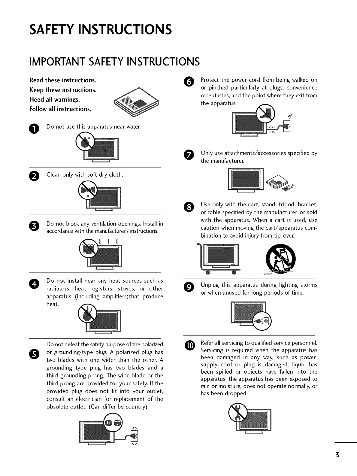
Read these instructions.
Keep these instructions.
Heed all warnings.
Follow all instructions.
O Do not use this apparatus near water.
O Clean only with soft dry cloth.
O Do not block any ventilation openings. Install in
accordance with the manufacturer's instructions.
Protect the power cord from being walked on
O
or pinched particularly at plugs, convenience
receptacles, and the point where they exit from
the apparatus.
Only use attachments/accessories specified by
the manufacturer.
Use only with the cart, stand, tripod, bracket,
0
or table specified by the manufacturer, or sold
with the apparatus. When a cart is used, use
caution when moving the cart/apparatus com-
bination to avoid injury from tip-over.
Do not install near any heat sources such as
O
radiators, heat registers, stoves, or other
apparatus (including amplifiers)that produce
heat.
Do not defeat the safety purpose of the polarized
or grounding-type plug. A polarized plug has
0
two blades with one wider than the other. A
grounding type plug has two blades and a
third grounding prong, The wide blade or the
third prong are provided for your safety. If the
provided plug does not fit into your outlet,
consult an electrician for replacement of the
obsolete outlet. (Can differ by country)
@
$3125A
O Unplug this apparatus during lighting storms
or when unused for long periods of time.
Refer all servicing to qualified service personnel.
@
Servicing is required when the apparatus has
been damaged in any way, such as power-
supply cord or plug is damaged, liquid has
been spilled or objects have fallen into the
apparatus, the apparatus has been exposed to
rain or moisture, does not operate normally, or
has been dropped.
3
SAFETYINSTRUCTIONS
O Never touch this apparatus or antenna during
a thunder or lighting storm.
When mounting a TV on the wall, make sure
®
not to install the TV by the hanging power and
signal cables on the back of the TV.
Do not allow an impact shock or any objects to
®
fall into the product, and do not drop onto the
screen with something.
CAUTION concerning the Power Cord:
O
It is recommend that appliances be placed
upon a dedicated circuit; that is, a single
outlet circuit which powers only that appliance
and has no additional outlets or branch
circuits. Check the specification page of this
owner's manual to be certain.
Do not connect too many appliances to the
same AC power outlet as this could result in
fire or electric shock.
Do not overload wall outlets. Overloaded wall
outlets, loose or damaged wall outlets, extension
cords, frayed power cords, or damaged or
cracked wire insulation are dangerous. Any of
these conditions could result in electric shock
or fire. Periodically examine the cord of your
appliance, and if its appearance indicates damage
or deterioration, unplug it, discontinue use of
the appliance, and have the cord replaced with
an exact replacement part by an authorized
servicer. Protect the power cord from physical
or mechanical abuse, such as being twisted,
kinked, pinched, closed in a door, or walked
upon. Pay particular attention to plugs, wall
outlets, and the point where the cord exits the
appliance.
Do not make the TV with the power cord
plugged in. Do not use a damaged or loose
power cord. Be sure do grasp the plug when
unplugging the power cord. Do not pull on the
power cord to unplug the TV.
WARNING - To reduce the risk of fire or electrical
0
shock, do not expose this product to rain,
moisture or other liquids. Do not touch the TV
with wet hands. Do not install this product
near flammable objects such as gasoline or
candles or expose the TV to direct air
conditioning.
Do not expose to dripping or splashing and do
@
not place objects filled with liquids, such as
vases, cups, etc. on or over the apparatus (e.g.
on shelves above the unit).
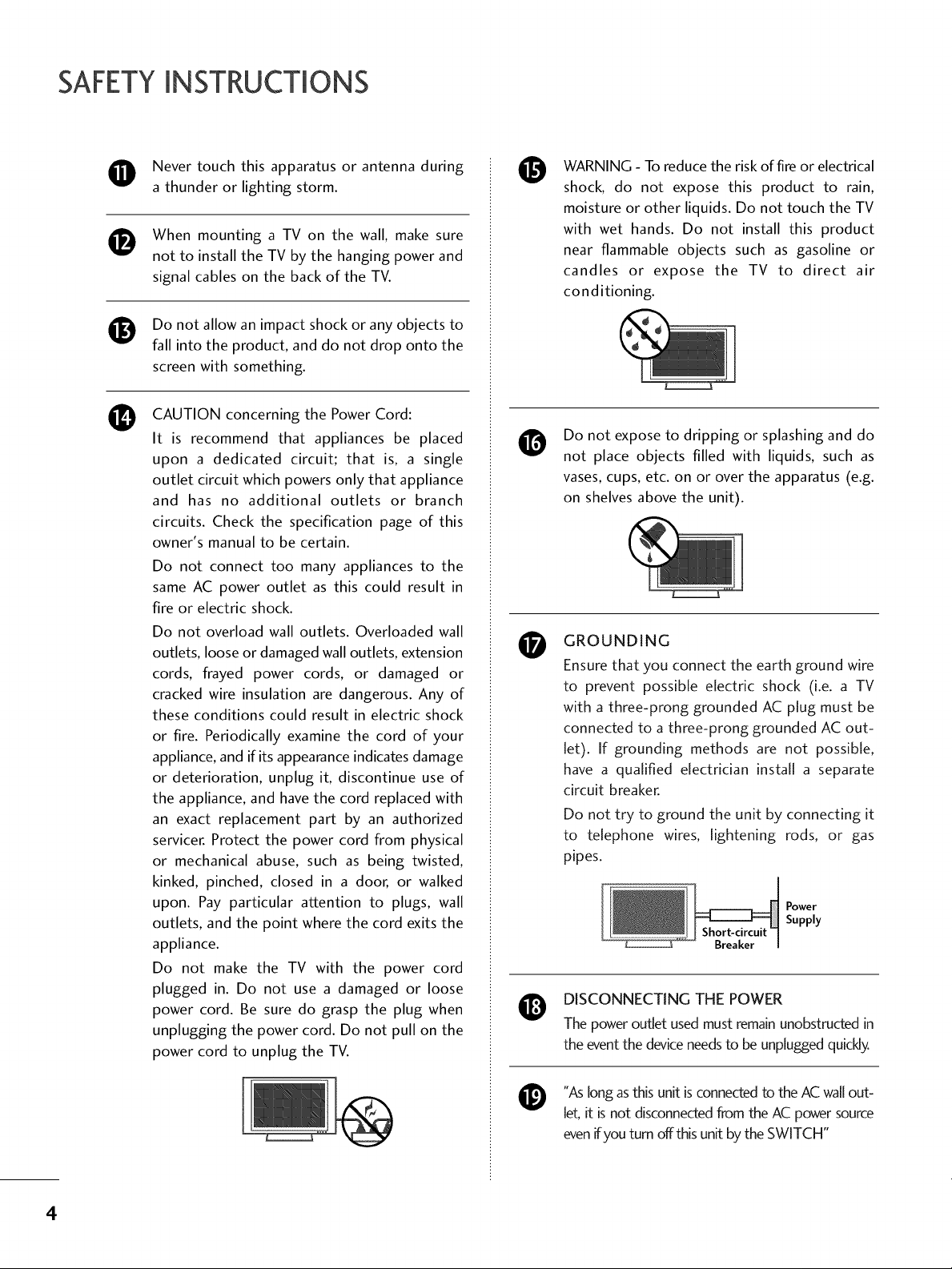
GROUNDING
0
Ensure that you connect the earth ground wire
to prevent possible electric shock (i.e. a TV
with a three-prong grounded AC plug must be
connected to a three-prong grounded AC out-
let). If grounding methods are not possible,
have a qualified electrician install a separate
circuit breaker.
Do not try to ground the unit by connecting it
to telephone wires, lightening rods, or gas
pipes.
DISCONNECTING THE POWER
The power outlet used must remain unobstructed in
the event the device needs to be unplugged quickly.
Power
Supply
"As long as this unit is connected to the AC wall out-
@
[
let, it is not disconnected from the AC power source
evenifyou turn offthis unit by the SWITCH"
4
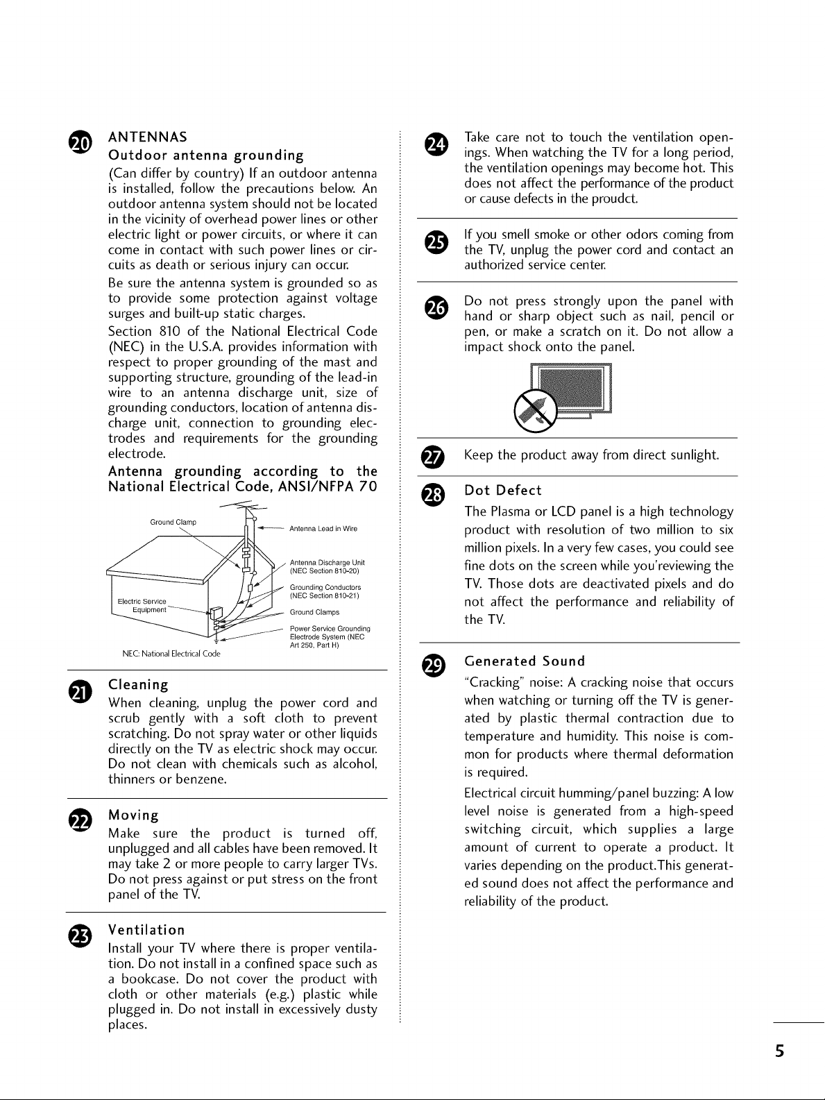
ANTENNAS
@
Outdoor antenna grounding
(Can differ by country) If an outdoor antenna
is installed, follow the precautions below. An
outdoor antenna system should not be located
in the vicinity of overhead power lines or other
electric light or power circuits, or where it can
come in contact with such power lines or cir-
cuits as death or serious injury can occur.
Be sure the antenna system is grounded so as
to provide some protection against voltage
surges and built-up static charges.
Section 810 of the National Electrical Code
(NEC) in the U.S.A. provides information with
respect to proper grounding of the mast and
supporting structure, grounding of the lead-in
wire to an antenna discharge unit, size of
grounding conductors, location of antenna dis-
charge unit, connection to grounding elec-
trodes and requirements for the grounding
electrode.
Antenna grounding according to the
National Electrical Code, ANSI/NFPA 70
Ground Clamp
NEC: National Electrical Code
Cleaning
O
When cleaning, unplug the power cord and
scrub gently with a soft cloth to prevent
scratching. Do not spray water or other liquids
directly on the TV as electric shock may occur.
Do not clean with chemicals such as alcohol,
thinners or benzene.
i_ Moving
Make sure the product is turned off,
unplugged and all cables have been removed. It
may take 2 or more people to carry larger TVs.
Do not press against or put stress on the front
panel of the TV.
Antenna Lead in Wire
Antenna Discharge Unit
(NEC Section 810-20)
Grounding Conductors
(NEC Section 810-21)
Ground Clamps
Power Service Grounding
Electrode System (NEC
Art 250, Part H)
Take care not to touch the ventilation open-
@
ings. When watching the TV for a long period,
the ventilation openings may become hot. This
does not affect the performance of the product
or cause defects in the proudct.
If you smell smoke or other odors coming from
the TV, unplug the power cord and contact an
authorized service center.
Do not press strongly upon the panel with
@
hand or sharp object such as nail, pencil or
pen, or make a scratch on it. Do not allow a
impact shock onto the panel.
t_t Keep the product awayfrom direct sunlight.
Dot Defect
The Plasma or LCD panel is a high technology
product with resolution of two million to six
million pixels. In a very few cases, you could see
fine dots on the screen while you'reviewing the
TV. Those dots are deactivated pixels and do
not affect the performance and reliability of
the TV.
@
Generated Sound
"Cracking" noise: A cracking noise that occurs
when watching or turning off the TV is gener-
ated by plastic thermal contraction due to
temperature and humidity. This noise is com-
mon for products where thermal deformation
is required.
Electrical circuit humming/panel buzzing: A low
level noise is generated from a high-speed
switching circuit, which supplies a large
amount of current to operate a product. It
varies depending on the product.This generat-
ed sound does not affect the performance and
reliability of the product.
Ventilation
Install your TV where there is proper ventila-
tion. Do not install in a confined space such as
a bookcase. Do not cover the product with
cloth or other materials (e.g.) plastic while
plugged in. Do not install in excessively dusty
places.
S
CONTENTS
WARNING / CAUTION ............................ 2
SAFETY INSTRUCTIONS .......................... 3
FEATURES OF THIS TV .............................8
Accessories ...................................................... 9
Front Panel Information ................................... 10
Back Panel Information ..................................... 11
Stand Instruction ............................................. 12
Cable Management ......................................... 14
Desktop Pedestal Installation ............................ 15
Swivel Stand .................................................... 15
VESA Wall Mounting ........................................ 16
Securing the TV to the wall to prevent falling
when the TV is used on a stand ....................... 17
Antenna or Cable Connection .......................... 18
- Channel Editing ........................................ 40
Channel List.................................................... 41
FavoriteChannel Setup .................................... 42
FavoriteChannel List ....................................... 42
Brief Information ............................................. 43
Input List ........................................................ 44
Input Label ..................................................... 45
Picture Size (Aspect Ratio) Control .................. 46
Power Saving................................................... 48
Preset Picture Settings(Picture Mode) .............. 49
Manual Picture Adjustment - User Mode .......... 50
Picture Improvement Technology ...................... 51
Expert Picture Control ..................................... 52
Picture Reset ................................................. 54
Image Sticking Minimization (ISM) Method ....... 55
HD Receiver Setup ......................................... 19
DVD Setup ..................................................... 22
VCR Setup ..................................................... 24
Other A/V Source Setup ................................. 25
Audio Out Connection ................................... 26
PC Setup ........................................................ 27
Remote Control Functions ............................... 32
Turning On TV ................................................ 34
Channel Selection ........................................... 34
Volume Adjustment ......................................... 34
Initial Setting .................................................. 35
On-Screen Menus Selection ............................ 36
Quick Menu ................................................... 37
Channel Setup
- Auto Scan (Auto Tuning) ........................... 38
- Add / Delete Channel (Manual Tuning) ...... 39
Auto Volume Leveler(Auto Volume) ................. 56
Preset Sound Settings (Sound Mode) ............... 57
Sound Setting Adjustment - User Mode ........... 58
Infinite Surround ............................................ 58
Balance .......................................................... 59
TV SpeakersOn/Off Setup .............................. 60
Audio Reset ................................................... 61
Stereo/SAP Broadcasts Setup .......................... 62
Audio Language .............................................. 63
On-Screen Menus LanguageSelection ............. 64
Caption Mode
- Analog Broadcasting System Captions ....... 65
- Digital Broadcasting System Captions ........ 66
- Caption Option ....................................... 67
6
Clock Setting
- Auto Clock Setup .................................... 68
- Manual Clock Setup ................................. 69
Auto On/Off Time Setting .............................. 70
Sleep Timer Setting ......................................... 71
Set Password& LockSystem ........................... 72
Channel Blocking ............................................ 75
Movie & TV Rating .......................................... 76
Downloadable Rating ...................................... 79
External Input Blocking .................................... 80
Key lock .......................................................... 81
Troubleshooting .............................................. 82
Maintenance ................................................... 84
Product Specifications ..................................... 85
IR Codes ....................................................... 86
External Control Through RS-232C .................. 88
7
FEATURES OF THIS TV
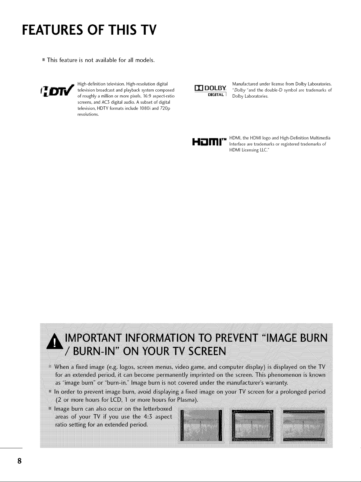
,,,IThis feature is not available for all models.
High-definition television. High-resolution digital
television broadcast and playback system composed
of roughly a million or more pixels, 16:9 aspect-ratio
screens, and AC3 digital audio. A subset of digital
television, HDTV formats include 1080i and 720p
resolutions.
I'_ DOLBY
DIGITAL[
Manufactured under license from Dolby Laboratories.
"Dolby "and the doub[e-D symbol are trademarks of
Dolby Laboratories.
HDMI, the HDMI logo and High-Definition Multimedia
HDmr Interface are trademarks or registered trademarks of
HDMI Licensing LLC."
8
PREPARATION
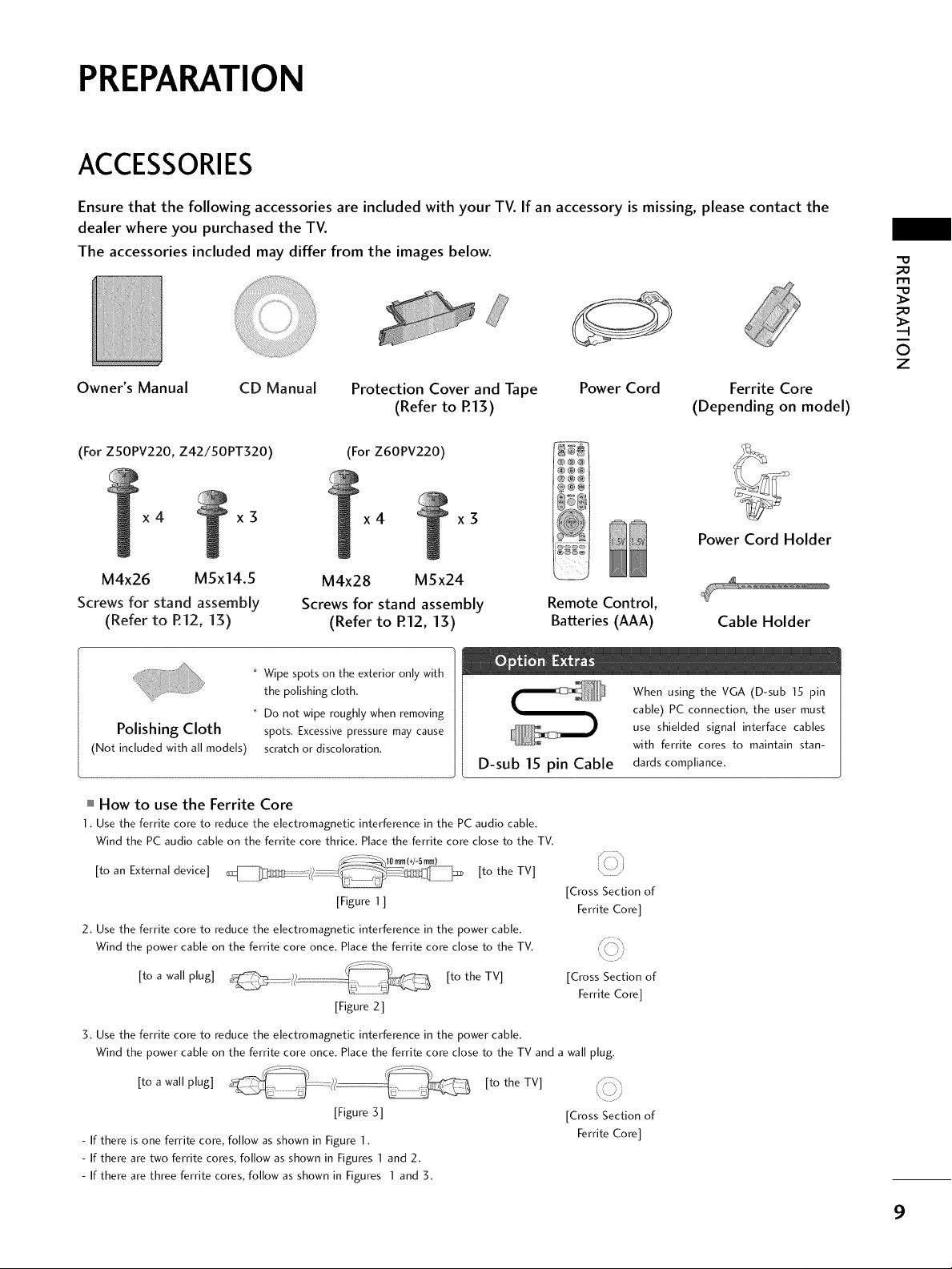
ACCESSORIES
Ensure that the following accessories are included with your TV. If an accessory is missing, please contact the
dealer where you purchased the TV.
The accessories included may differ from the images below.
_D
r'_
_D
Zii!i
Owner's Manual
(For ZSOPV220, Z42/50PT320) (For Z60PV220)
x4 x3
M4x26 M5x14.5
Screws for stand assembly
(Refer to R12, 13)
Polishing Cloth
(Not included with all models)
""_How to use the Ferrite Core
1, Use the ferrite core to reduce the electromagnetic interference in the PC audio cable,
Wind the PC audio cable on the ferrite core thrice, Place the ferrite core close to the TV,
CD Manual Protection Cover and Tape Power Cord
(Refer to R13)
x4 x3
M4x28 MSx24
Screws for stand assembly
(Refer to R12, 13)
* Wipe spots on the exterior only with
the polishing cloth.
* Do not wipe roughly when removing
spots. Excessive pressure may cause
scratch or discoloration.
D-sub 15 pin Cable
Remote Control,
Batteries (AAA)
When using the VGA (D-sub 15 pin
cable) PC connection, the user must
use shielded signal interface cables
with ferrite cores to maintain stan-
dards compliance,
O
z
Ferrite Core
(Depending on model)
Power Cord Holder
Cable Holder
[to an External device] [to the TV]
[Figure 1 ]
2, Use the ferrite core to reduce the electromagnetic interference in the power cable,
Wind the power cable on the ferrite core once, Place the ferrite core close to the TV,
[to a wall plug] [to the TV]
[Figure 2]
3, Use the ferrite core to reduce the electromagnetic interference in the power cable,
Wind the power cable on the ferrite core once, Place the ferrite core close to the TV and a wall plug,
[to a wall plug] [to the TV]
[Figure 3] [Cross Section of
- If there is one ferrite core, follow as shown in Figure 1,
- If there are two ferrite cores, follow as shown in Figures ] and 2,
- If there are three ferrite cores, follow as shown in Figures I and 3,
[Cross Section of
[Cross Section of
Ferrite Core]
Ferrite Core]
Ferrite Core]
9
PREPARATION
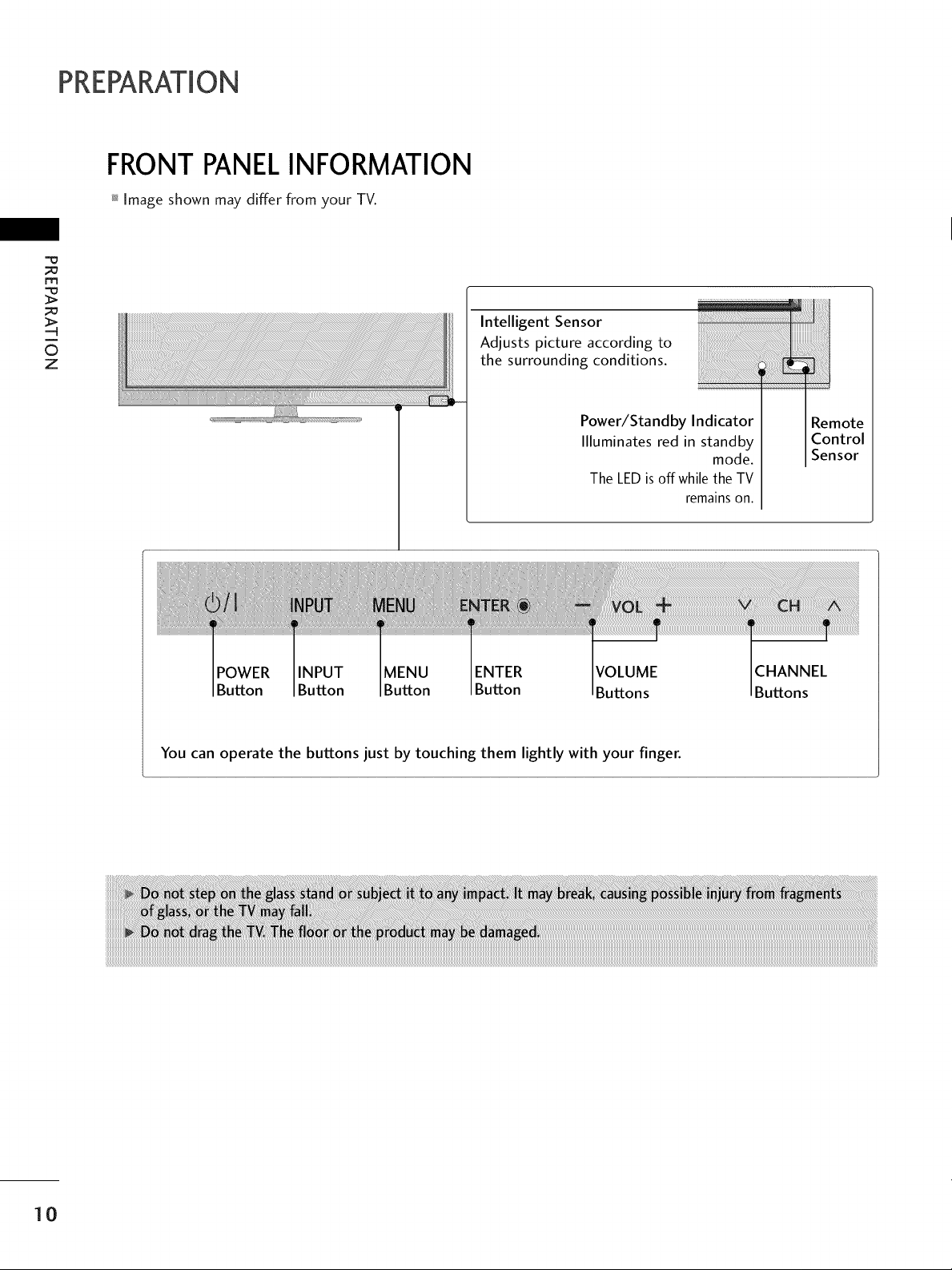
FRONTPANELINFORMATION
Image shown may differ from your TV.
;=o
m
mode.
CHANNEL
Buttons
_i_ii!ii!ii!ii!ii!ii!ii!ii!ii!ii!ii!ii!ii!ii!ii!ii!ii!ii!ii!ii!iiiiiilli!iiiiiiiii:iiiilili
Remote
Control
Sensor
i
©
z
Intelligent Sensor
Adjusts picture according to
the surrounding conditions.
Power/Standby Indicator
Illuminates red in standby
The LED is off while the TV
remains on.
POWER INPUT MENU ENTER VOLUME
Button Button Button Button Buttons
You can operate the buttons just by touching them lightly with your finger.
10
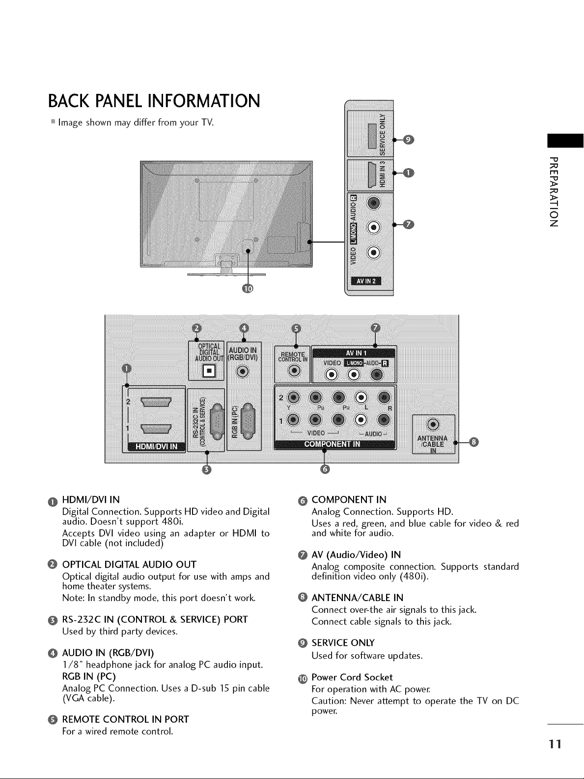
BACKPANELINFORMATION
Image shown may differ from your TV.
m
©
z
iiiiiiiiiiii_
!i!i!i!!!i!iiiiiii®iiil,iii!i
HDMI/DVI IN
Digital Connection. Supports HD video and Digital
audio. Doesn't support 480i.
Accepts DVl video using an adapter or HDMI to
DVl cable (not included)
OPTICAL DIGITAL AUDIO OUT
Optical digital audio output for use with amps and
home theater systems.
Note: In standby mode, this port doesn't work.
RS-232C IN (CONTROL & SERVICE) PORT
Used by third party devices.
AUDIO IN (RGB/DVI)
I/8" headphone jack for analog PC audio input.
RGB IN (PC)
Analog PC Connection. Uses a D-sub 15 pin cable
(VGA cable).
REMOTE CONTROL IN PORT
For awired remote control.
COMPONENT IN
@
Analog Connection. Supports HD.
Uses a red, green, and blue cable for video & red
and white for audio.
@
AV (Audio/Video) IN
Analog composite connection. Supports standard
definition video only (480i).
@
ANTENNA/CABLE IN
Connect over-the air signals to this jack.
Connect cable signals to this jack.
SERVICE ONLY
@
Used for software updates.
Power Cord Socket
@
For operation with AC power.
Caution: Never attempt to operate the TV on DC
power.
11
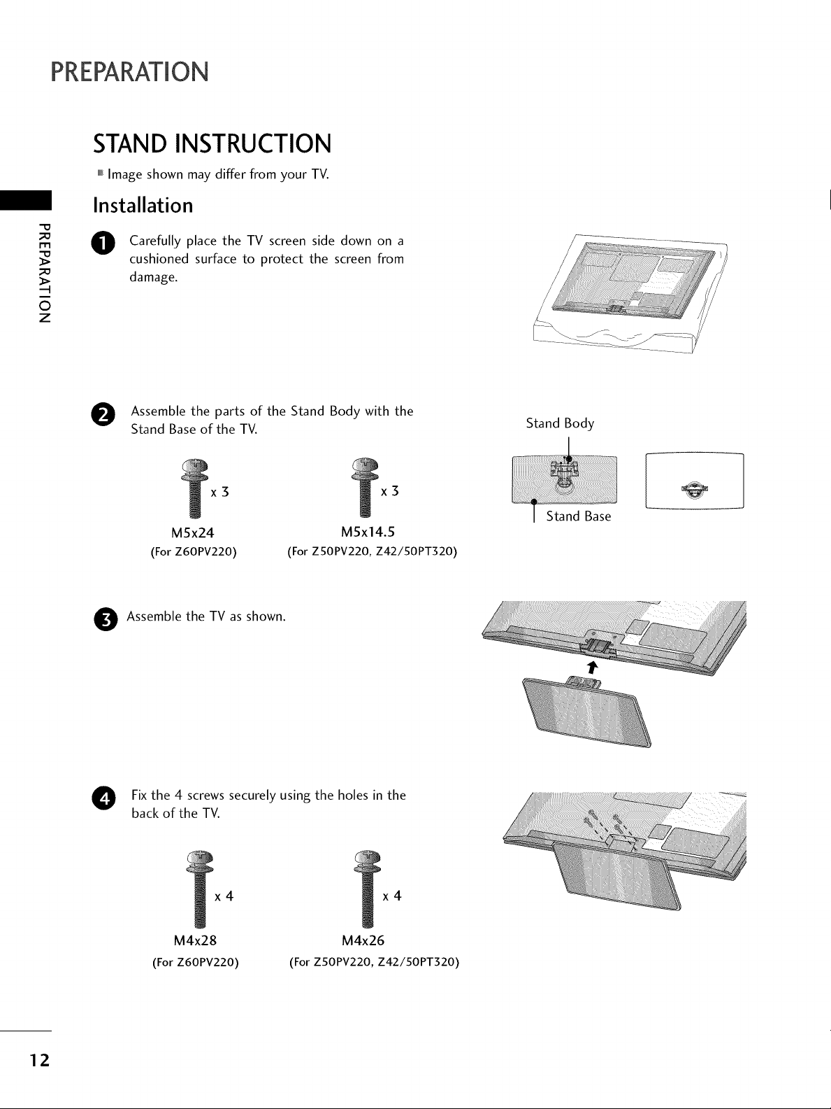
PREPARATION
STAND INSTRUCTION
,,,IImage shown may differ from your TV.
Installation
"0
_o
m
_o
©
z
Carefully place the TV screen side down on a
cushioned surface to protect the screen from
damage.
e Assemble the parts of the Stand Body with the
Stand Base of the TV.
x3
M5x24
(For Z60PV220)
Assemble the TV as shown.
(For ZSOPV220, Z42/50PT320)
x3
M5x14.5
Fix the 4 screws securely using the holes in the
back of the TV.
Stand Body
12
x4 x4
M4x28
(For Z60PV220)
M4x26
(For Z50PV220, Z42/50PT320)
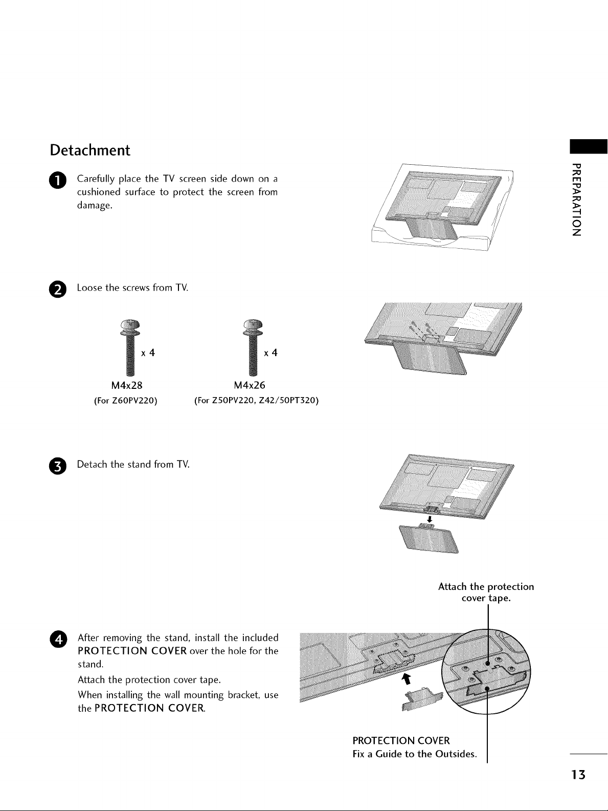
Detachment
O Carefully place the TV screen side down on a
cushioned surface to protect the screen from
damage.
Loose the screws from TV.
_D
m
_D
_!i_!_!_!_!_!_!_ii_ii_ii_ii_ii_iiii_i_ii_iiiiiiiiiiiiiiiiiiii!i_!i!!!!!i!i!i!_i_
©
z
....._:_-_
x4
M4x28
(For Z60PV220)
Detach the stand from TV.
After removing the stand, install the included
0
PROTECTION COVER over the hole for the
stand.
Attach the protection cover tape.
When installing the wall mounting bracket, use
the PROTECTION COVER.
(For ZSOPV220, Z42/50PT320)
x4
M4x26
Attach the protection
cover tape.
PROTECTION COVER
Fix a Guide to the Outsides.
13
PREPARATION
CABLEMANAGEMENT
,,,IImage shown may differ from your TV.
_e
m
_e
©
z
0
0
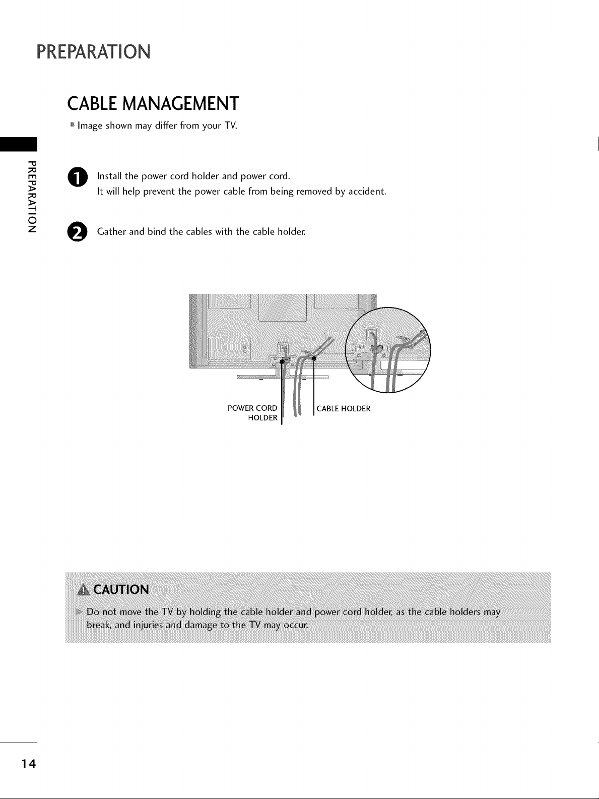
Install the power cord holder and power cord.
It will help prevent the power cable from being removed by accident.
Gather and bind the cables with the cable holder.
POWER CORD CABLE HOLDER
HOLDER
14
DESKTOP PEDESTALINSTALLATION
,,,IImage shown may differ from your TV.
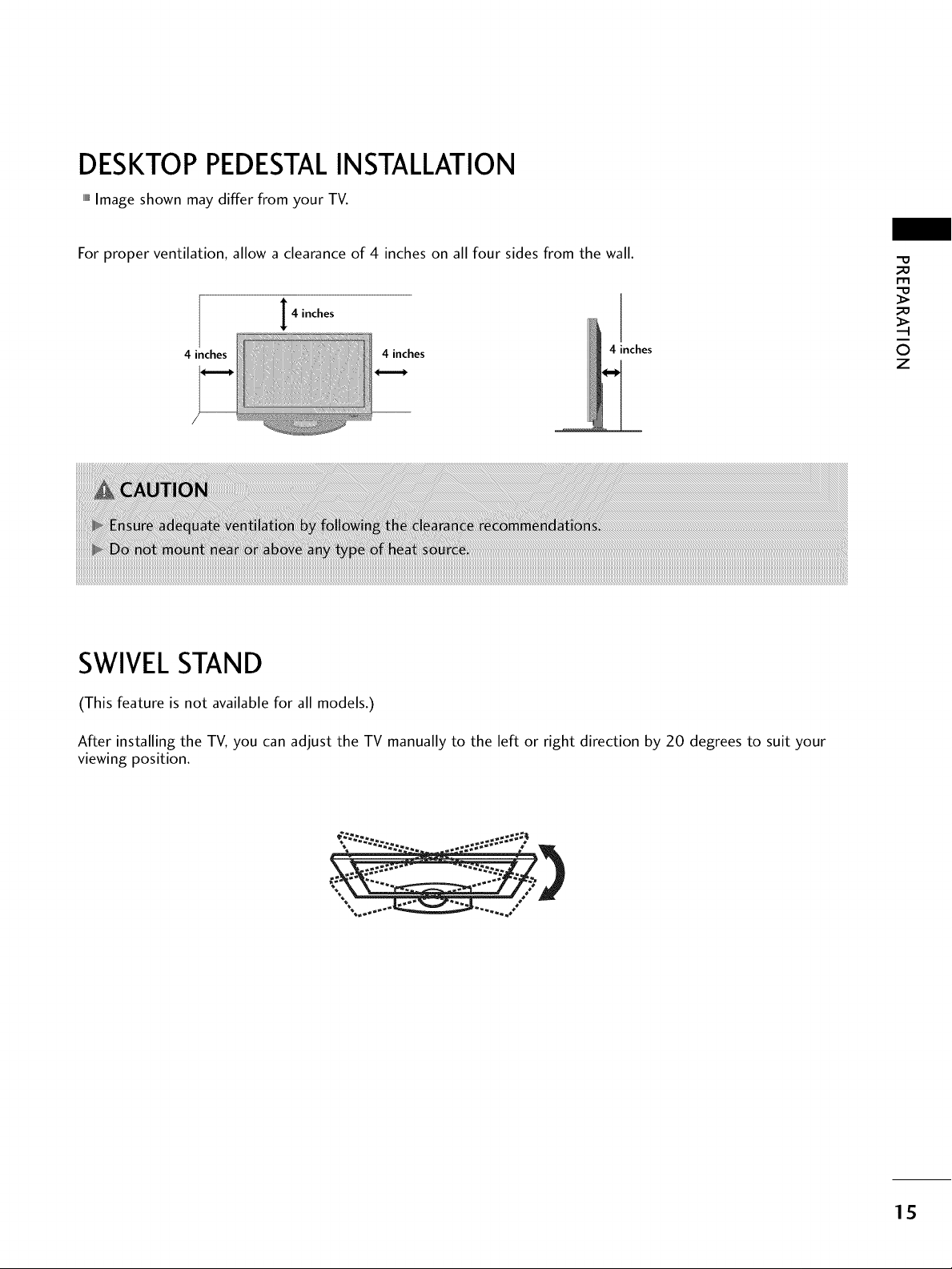
For proper ventilation, allow a clearance of 4 inches on all four sides from the wall.
4 inches
4 inches 4 inches
4 inches
SWIVELSTAND
(This feature is not available for all models.)
_0
I"I"1
_o
©
z
After installing the TV, you can adjust the TV manually to the left or right direction by 20 degrees to suit your
viewing position.
15
PREPARATION
VESAWALLMOUNTING
Install your wall mount on a solid wall perpendicular to the floor. When attaching to other building materials, please
-O
_a
r'rl
_a
0
z
contact your nearest installer.
If installed on a ceiling or slanted wall, it may fall and result in severe personal injury.
We recommend that you use an LG brand wall mount when mounting the TV to a wall.
LG recommends that wall mounting be performed by a qualified professional installer.
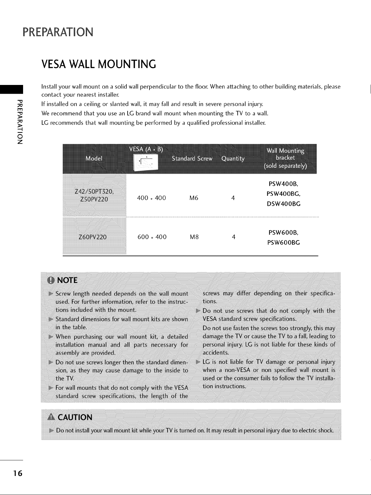
600 • 400 M8 4
PSW600B,
PSW600BG
16
SECURINGTHE TV TO THE WALLTO PREVENTFALLING
WHEN THE TV IS USED ON A STAND
You should purchase necessary components to prevent the TV from tipping over (when not using a wall mount).
llllll_Image shown may differ from your TV.
We recommend that you set up the TV close to a wall so it cannot fall over if pushed backwards.
Additionally, we recommend that the TV be attached to a wall so it cannot be pulled in a forward direction,
potentially causing injury or damaging the product.
Caution: Please make sure that children don't climb on or hang from the TV.
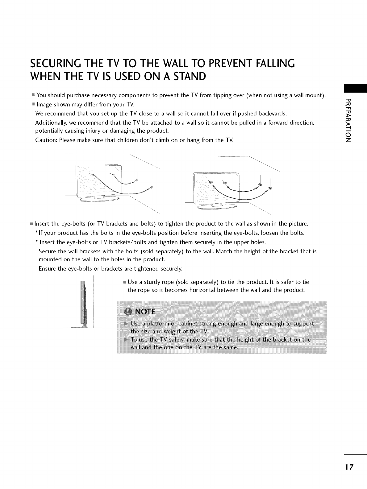
Insert the eye-bolts (or TV brackets and bolts) to tighten the product to the wall as shown in the picture.
If your product has the bolts in the eye-bolts position before inserting the eye-bolts, loosen the bolts.
Insert the eye-bolts or TV brackets/bolts and tighten them securely in the upper holes.
Secure the wall brackets with the bolts (sold separately) to the wall. Match the height of the bracket that is
mounted on the wall to the holes in the product.
Ensure the eye-bolts or brackets are tightened securely.
m
0
z
01_Use a sturdy rope (sold separately) to tie the product. It is safer to tie
the rope so it becomes horizontal between the wall and the product.
17
PREPARATION
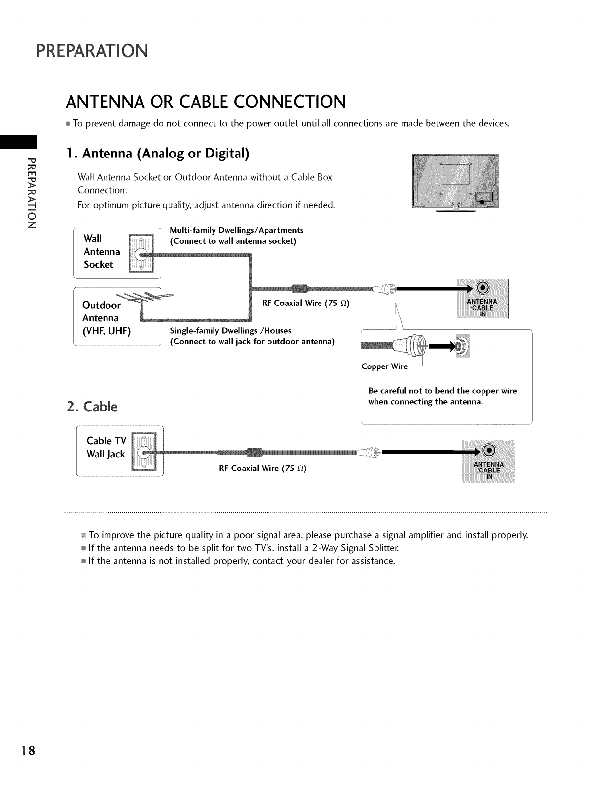
ANTENNA OR CABLECONNECTION
To prevent damage do not connect to the power outlet until all connections are made between the devices.
1. Antenna (Analog or Digital)
m
©
z
Wall Antenna Socket or Outdoor Antenna without a Cable Box
Connection.
For optimum picture quality, adjust antenna direction if needed.
_0_o_ "/ Multi-family Dwellings/Apartments
Antenna
Socket
Wall enna socket)
Outdo RFCoaxialWire (7S _)
Antenn
(VHF, UHF) I Single-family Dwellings/Houses
(Connect to wall jack for outdoor antenna)
Be careful not to bend the copper wire
2. Cable
when connecting the antenna.
Cable TV
Wall Jack
To improve the picture quality in a poor signal area, please purchase a signal amplifier and install properly.
01_If the antenna needs to be split for two TV's, install a 2-Way Signal Splitter.
01_If the antenna is not installed properly, contact your dealer for assistance.
18
EXTERNAL EQUIPMENT SETUP
HD RECEIVERSETUP
01_To prevent the equipment damage, never plug in any power cords until you have finished connecting all equipment.
,,,iImage shown may differ from your TV.
This TV can receive Digital Over-the-air/Cable signals without an external digital set-top box. However, if you do
receive digital signals from a digital set-top box or other digital external device, refer to the figure as shown below.
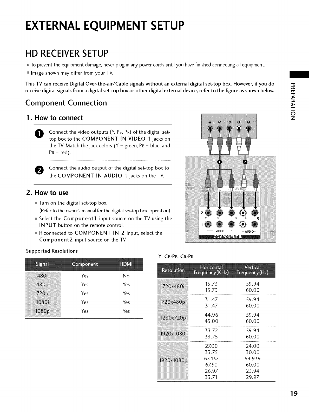
Component Connection
I. How to connect
Connect the video outputs (Y, PB, PR) of the digital set-
O
top box to the COMPONENT IN VIDEO 1 jacks on
the TV. Match the jack colors (Y = green, PB = blue, and
PR = red).
O onnect the audio output of the digital set-top boxto
the COMPONENT IN AUDIO 1 jacks on the TV.
2. How to use
01_Turn on the digital set-top box.
(Referto the owner'smanualforthe digitalset-top box.operation)
0_Select the Component1 input source on the TV using the
INPUT button on the remote control.
01_If connected to COMPONENT IN 2 input, select the
Component2 input source on the TV.
_D
m
_D
©
z
Supported Resolutions
Yes No
Yes Yes
Yes Yes
Yes Yes
Yes Yes
Y, CB/PB, CR/PR
15.73 59.94
15.73 60.00
31.47 59.94
31.47 60.00
44.96 59.94
45.00 60.00
33.72 59.94
33.75 60.00
2Z00 24.00
33.75 30.00
6Z432 59.939
6Z50 60.00
26.97 23.94
33.71 29.97
19
m
x
-4
m
z
F-
ro
_D
c
i
m
z
-4
m
-4
c
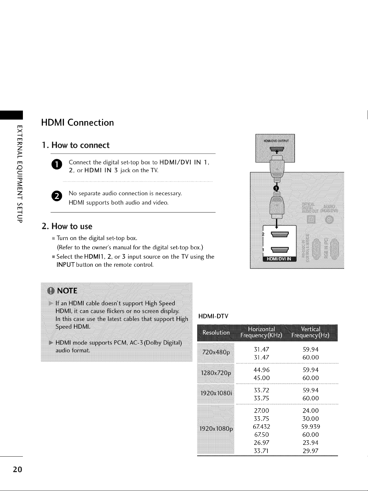
HDMI Connection
1. How to connect
O onnect the digital set-top box to HDMI/DVI IN 1,
2, or HDMI IN 3 jack on the TV.
O No separate audio connection is necessary.
HDMI supports both audio and video.
2. How to use
Turn on the digital set-top box.
(Refer to the owner's manual for the digital set-top box.)
Select the HDMI], 2, or 3 input source on the TV using the
INPUT button on the remote control.
20
HDMI-DTV
31.47 59.94
31.47 60.00
44.96 59.94
45.00 60.00
_i_i_i_i!i!iiiiiiiiiiii_ii_iiiiiiiiiiiiiiiiiiiii_i_i_i!i!i!iiiiiiii_i_i_i_i!i!i!iiiiiiiiiiiiiiiiiiiiiiii_iiiiiiiiiiiiii_ii_iiiiii_i_i!_!i!i_i_i_!_i_i;_!i_i_i_i_i!i_ii_ii_ii_ii_ii_i_ii_i
: 33.72 s9.94
33.75 60.00
2Z00 24.00
33.75 30.00
6Z432 59.939
6Z50 60.00
26.97 23.94
33.71 29.97
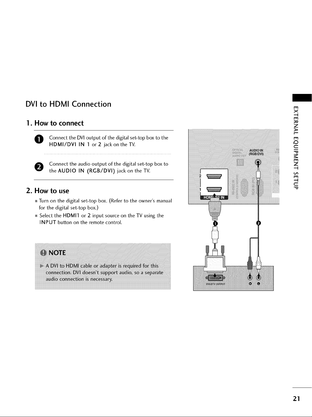
DVI to HDMI Connection
1. How to connect
m
x
m
z
O onnect the DVI output of the digital set-top box to the
HDMI/DVl IN 1 or 2 jackon the TV.
O Connect the audio output of the digital set-top box to
the AUDIO IN (RGB/DVl) jack on the TV.
2. How to use
01_Turn on the digital set-top box. (Refer to the owner's manual
for the digital set-top box.)
01_Select the HDMI1 or 2 input source on the TV using the
INPUT button on the remote control.
m
XD
c
m
z
m
c
21
EXTERNALEQUIPMENT SETUP
DVD SETUP
Component Connection
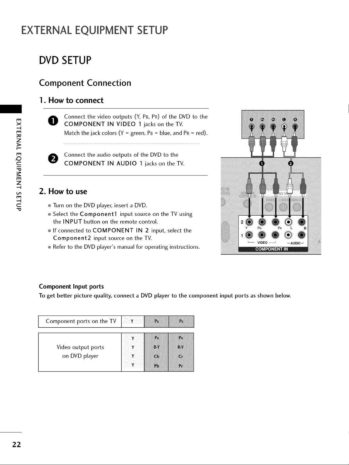
1. How to connect
Connect the video outputs (Y, PB, PR) of the DVD to the
x
r_l
_o
z
r_l
X:)
c
"0
r_l
z
r_l
c
"0
O
COMPONENT IN VIDEO 1 jacks on the TV.
Match the jack colors (Y = green, PB = blue, and PR= red).
O Connect the audio outputs of the DVD to the
COMPONENT IN AUDIO 1 jacks on the TV.
2. How to use
Turn on the DVD player, insert a DVD.
Select the Component1 input source on the TV using
the INPUT button on the remote control.
If connected to COMPONENT IN 2 input, select the
Component2 input source on the TV.
Refer to the DVD player's manual for operating instructions.
22
Component Input ports
To get better picture quality, connect a DVD player to the component input ports asshown below.
Component ports on the TV
Video output ports
on DVD player
HDMI Connection
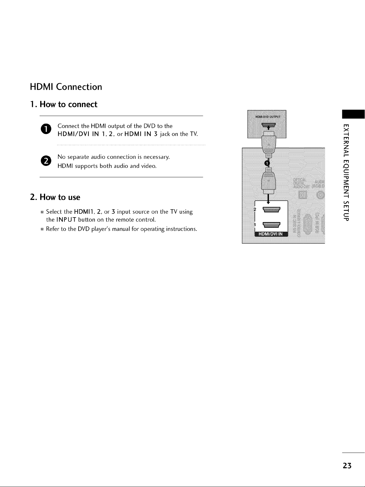
1. How to connect
O Connect the HDMI output of the DVD to the
HDMI/DVI IN 1,2, or HDMI IN 3 jack on the TV.
m
x
m
_o
z
No separate audio connection is necessary.
HDMI supports both audio and video.
2. How to use
01_Select the HDMI1, 2, or 3 input source on the TV using
the INPUT button on the remote control.
01_Refer to the DVD player's manual for operating instructions.
m
X:)
c
"O
m
z
m
c
"O
23
EXTERNALEQUIPMENT SETUP
VCRSETUP
Antenna Connection
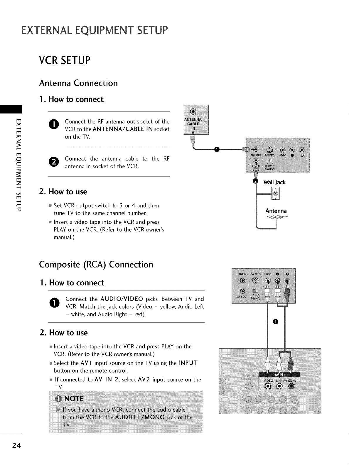
1. How to connect
x
r_l
_o
z
r_l
X:)
c
"O
r_l
z
r_l
c
"O
Connect the RF antenna out socket of the
VCR to the ANTENNA/CABLE IN socket
on the TV.
Connect the antenna cable to the RF
antenna in socket of the VCR.
2. How to use
Set VCR output switch to 3 or 4 and then
tune TV to the same channel number.
Insert a video tape into the VCR and press
PLAY on the VCR. (Refer to the VCR owner's
manual.)
Composite (RCA)
Connection
I. How to connect
Wall Jack
Antenna
24
Connect the AUDIO/VIDEO jacks between TV and
VCR. Match the jack colors (Video = yellow, Audio Left
= white, and Audio Right = red)
2. How to use
01_Insert a video tape into the VCR and press PLAY on the
VCR. (Refer to the VCR owner's manual.)
01_Select the AVl input source on the TV using the INPUT
button on the remote control.
01_If connected to AV IN 2, select AM2 input source on the
TV.
OTHERA/V SOURCESETUP
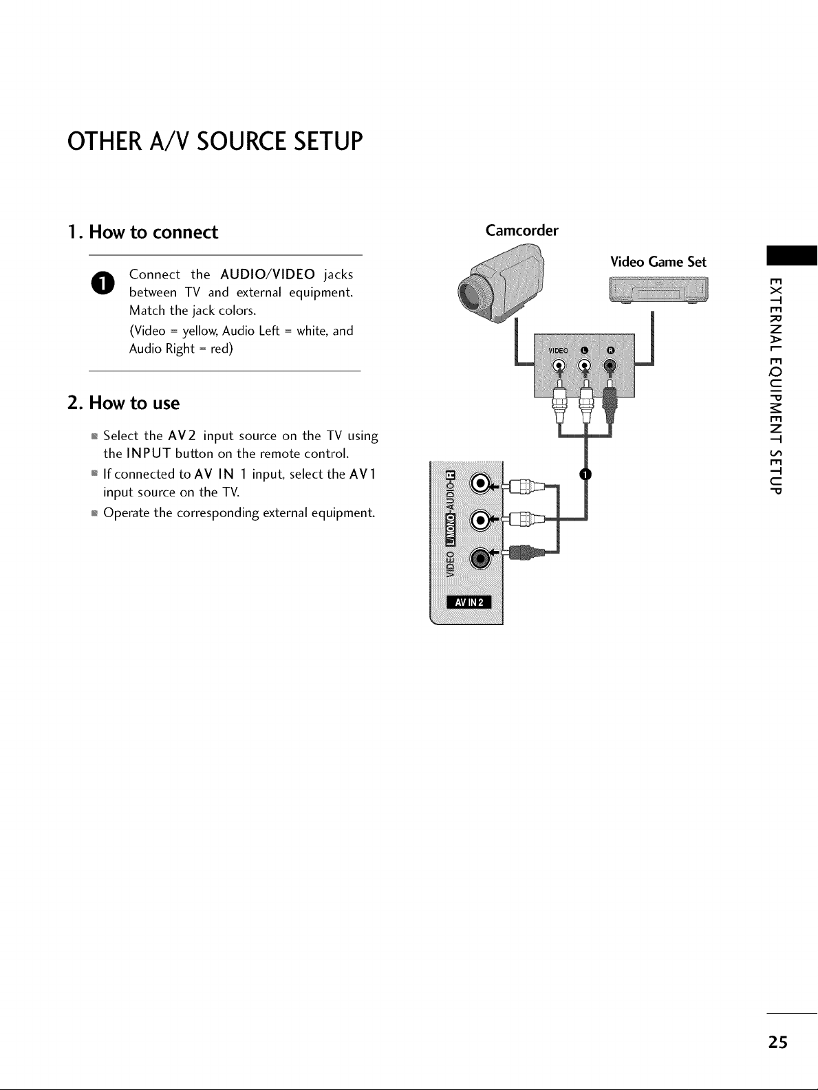
1. How to connect
Connect the AUDIO/VIDEO jacks
0
between TV and external equipment.
Match the jack colors.
(Video = yellow, Audio Left = white, and
Audio Right = red)
2. How to use
01_Select the AV2 input source on the TV using
the INPUT button on the remote control.
01_If connected to AV IN 1 input, select the AV 1
input source on the TV.
01_Operate the corresponding external equipment.
Camcorder
Video Game Set
X_
m
x
m
_o
z
m
c
m
z
m
c
-O
25
EXTERNALEQUIPMENT SETUP
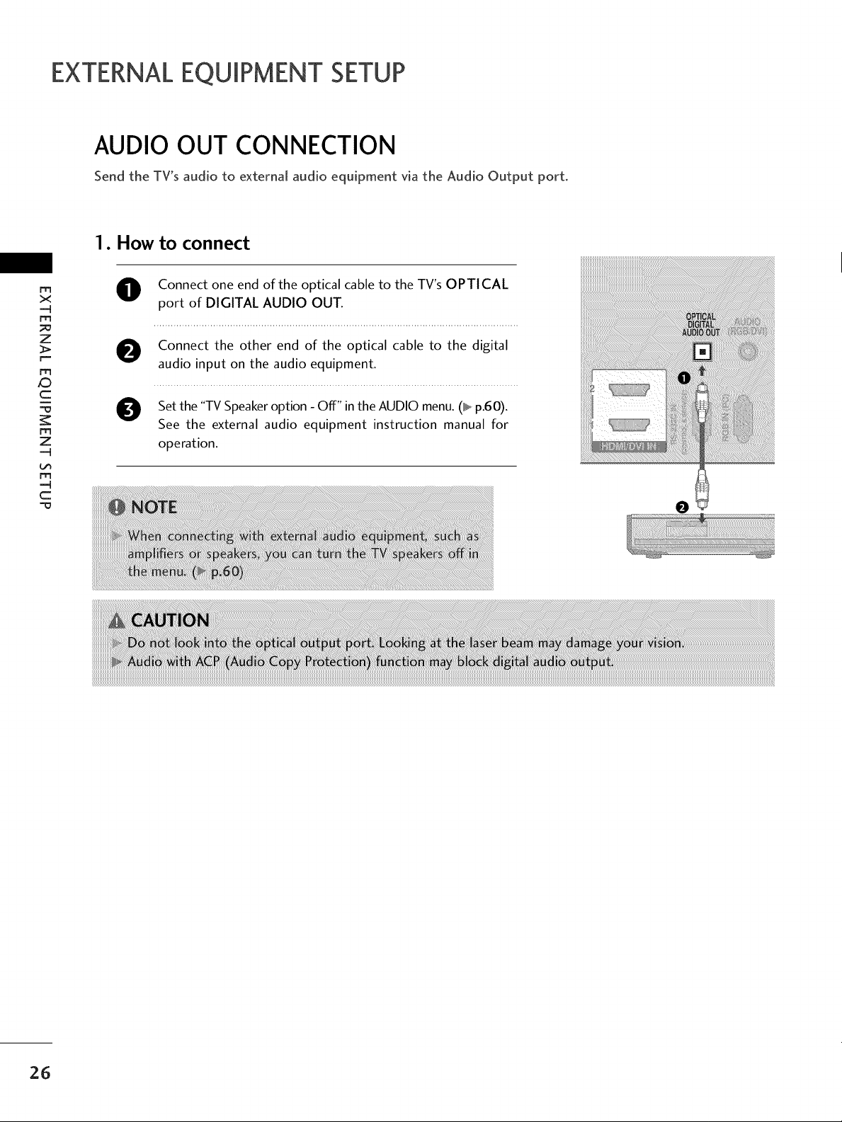
AUDIO OUT CONNECTION
Send the TV's audio to external audio equipment via the Audio Output port.
1. How to connect
rrt
x
m
_o
z
>.
r--
m
O Connect one end of the optical cable to the TV's OPTICAL
port of DIGITAL AUDIO OUT.
O onnect the other end of the optical cable to the digital
audio input on the audio equipment.
c
"=0
m
z
m
O Set the "TV Speaker option - Off" in the AUDIO menu. (_ p.60).
See the external audio equipment instruction manual for
operation.
c
26
PC SETUP
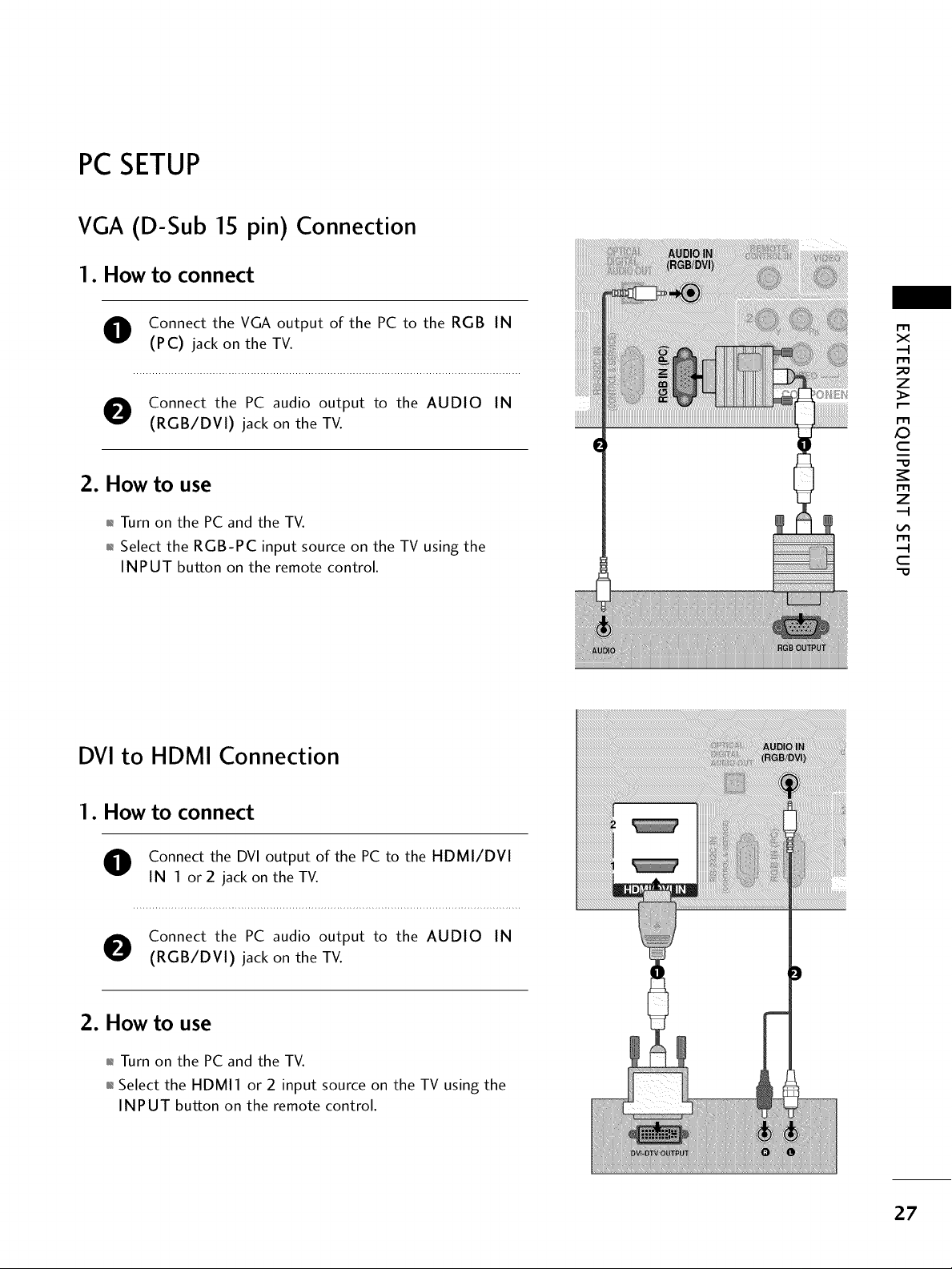
VGA (D-Sub 15 pin) Connection
1. How to connect
O onnect the VGA output of the PC to the RGB IN
(PC) jack on the TV.
O Connect the PC audio output to the AUDIO IN
(RGB/DVI) jack on the TV.
2. How to use
01_Turn on the PC and the TV.
01_Select the RGB-PC input source on the TV using the
INPUT button on the remote control.
DVI to HDMI Connection
m
x
m
_o
z
m
X:)
c
i
"O
m
z
m
c
"O
1. How to connect
O onnect the DVI output of the PC to the HDMI/DVI
IN 1 or 2 jack on the TV.
O Connect the PC audio output to the AUDIO IN
(RGB/DVI) jack on the TV.
2. How to use
01_Turn on the PC and the TV.
01_Select the HDMI1 or 2 input source on the TV using the
INPUT button on the remote control.
i!i!_!ii!i!i!_!ii]i!i!_!ii]i!i!_!ii]i!i!_!ii]i!i!_!ii]i!i!_!ii]i
27
EXTERNALEQUIPMENT SETUP
m
X
I"1"1
_o
z
I"1"1
x:)
C
I"1"1
z
I"1"1
C
"0
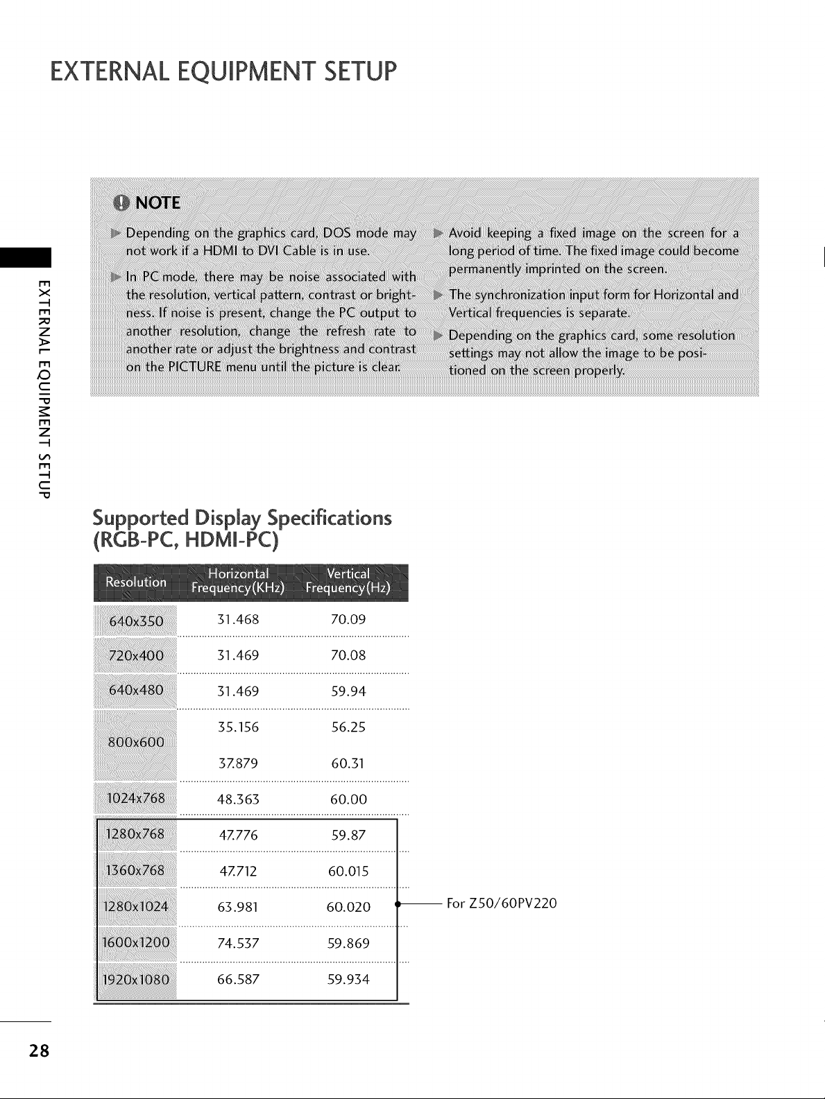
Supported Display Specifications
(R¢B-PC,HDMm-PC)
31.468 70.09
31.469 70.08
31.469 59.94
35.156 56.25
37.879 60.31
48.363 60.00
47.776 59.87
47.712 60.015
63.981 60.020 _ For ZSO/60PV220
28
74.537 59.869
66.587 59.934
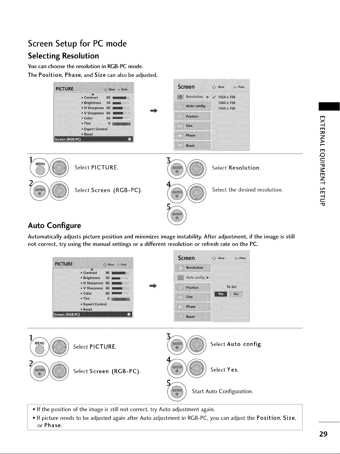
Screen Setup for PC mode
Selecting Resolution
You can choose the resolution in RGB-PC mode.
The Position, Phase, and Size can aJso be adjusted.
Select PICTURE. Select Resolution.
X_
r'_
x
r_
_D
z
r_
c
r_
z
Select Screen (RGB-PC).
Select the desired resolution.
Auto Configure
Automatically adjusts picture position and minimizes image instability. After adjustment, if the image is still
not correct, try using the manual settings or a different resolution or refresh rate on the PC.
Select PICTURE.
Select Auto config.
r_
c
Select Screen (RGB-PC).
Select Yes.
Start Auto Configuration.
• If the position of the image is still not correct, try Auto adjustment again.
• If picture needs to be adjusted again after Auto adjustment in RGB-PC, you can adjust the Position, Size,
or Phase.
29
 Loading...