

Page 1

SERVICE MANUAL
Product Type: PLASMA
Chassis: PA-63E
Manual Series:
Manual Part #: 38289S0065E
Model Line:
Product Year: 2007
Z50P3
Model Series:
CONTENTS
Description of Controls .................................................4
Specifications ..............................................................8
Adjustment Instructions ................................................9
Diagrams ...................................................................13
Parts List ...................................................................17
Schematics....................................................................
Published Oct. 2003
by Technical Publications
LG Electronics USA, Inc.
201 James Record Road,
Huntsville, Alabama 35824-1513
Copyright © 2003 by Zenith Electronics Corporation
Printed in Korea
http//www.zenithservice.com
Page 2

- 2 -
SAFETY PRECAUTIONS
Many electrical and mechanical parts in this chassis have special safety-related characteristics. These parts are identified by in
the Schematic Diagram and Replacement Parts List.
It is essential that these special safety parts should be replaced with the same components as recommended in this manual to
prevent X-RADIATION, Shock, Fire, or other Hazards.
Do not modify the original design without permission of manufacturer.
General Guidance
An lsolation Transformer should always be used during
the servicing of a receiver whose chassis is not isolated from
the AC power line. Use a transformer of adequate power rating
as this protects the technician from accidents resulting in
personal injury from electrical shocks.
It will also protect the receiver and it's components from being
damaged by accidental shorts of the circuitary that may be
inadvertently introduced during the service operation.
If any fuse (or Fusible Resistor) in this monitor is blown, replace
it with the same specified type.
When replacing a high wattage resistor (Oxide Metal Film
Resistor, over 1W), keep the resistor 10mm away from PCB.
Keep wires away from high voltage or high temperature parts.
Leakage Current Cold Check(Antenna Cold Check)
With the instrument AC plug removed from AC source,
connect an electrical jumper across the two AC plug prongs.
Place the AC switch in the on positioin, connect one lead of
ohm-meter to the AC plug prongs tied together and touch other
ohm-meter lead in turn to each exposed metallic parts such as
antenna terminals, phone jacks, etc.
If the exposed metallic part has a return path to the chassis, the
measured resistance should be between 1MΩ and 5.2MΩ.
When the exposed metal has no return path to the chassis the
reading must be infinite.
An other abnormality exists that must be corrected before the
receiver is returned to the customer.
Leakage Current Hot Check (See below Figure)
Plug the AC cord directly into the AC outlet.
Do not use a line Isolation Transformer during this check.
Connect 1.5K/10watt resistor in parallel with a 0.15uF capacitor
between a known good earth ground (Water Pipe, Conduit, etc.)
and the exposed metallic parts.
Measure the AC voltage across the resistor using AC
voltmeter with 1000 ohms/volt or more sensitivity.
Reverse plug the AC cord into the AC outlet and repeat AC
voltage measurements for each esposed metallic part. Any
voltage measured must not exceed 0.75 volt RMS which is
corresponds to 0.5mA.
In case any measurement is out of the limits sepcified, there is
possibility of shock hazard and the set must be checked and
repaired before it is returned to the customer.
Leakage Current Hot Check circuit
CANADA: LG Electronics Canada, Inc. 550 Matheson
Boulevard East Mississauga, Ontario L4Z 4G3
USA : LG Customer Interactive Center
P.O.Box 240007, 201 James Record Road Huntsville,
AL 35824
Digital TV Hotline 1-800-243-0000
1.5 Kohm/10W
To Instrument's
exposed
METALLIC PARTS
Good Earth Ground
such as WATER PIPE,
CONDUIT etc.
AC Volt-meter
IMPORTANT SAFETY NOTICE
0.15uF
Page 3

- 3 -
SPECIFICATIONS.................................................................4
ADJUSTMENT INSTRUCTIONS ..........................................5
PRINTED CIRCUIT BOARDS.............................................12
BLOCK DIAGRAM...............................................................15
EXPLODED VIEW...............................................................16
EXPLODED VIEW PARTS LIST .........................................17
REPLACEMENT PARTS LIST............................................18
SCHEMATIC DIAGRAM..........................................................
TABLE OF CONTENTS
Page 4

- 4 -
AC100-240V ~ 50/60Hz
NTSC-M, ATSC, 64 & 256 QAM
VHF 2 ~ 13, UHF 14 ~ 69,
CATV 1 ~ 135, CADTV 1 ~ 135, DTV 2 ~ 69
75 Ω
32 ~ 104°F (0 ~ 40°C)
Less than 80%
-4 ~ 140°F (-20 ~ 60°C)
Less than 85%
Z50P3
(50PC3DB-UE)
51.3 x 34.3 x 14.0 inches
1302.6 x 872.0 x 355.8 mm
51.3 x 31.9 x 4.2 inches
1302.6 x 810.0 x 107.7 mm
114.4 pounds / 51.9 kg
95.0 pounds / 43.1 kg
Dimensions
(Width x Height x Depth)
Weight
with stand
without stand
with stand
without stand
Power requirement
Television System
Program Coverage
External Antenna Impedance
Operating Temperature
Operating Humidity
Storage Temperature
Storage Humidity
Environmental
condition
• The specifications shown above may be changed without prior notice for quality improvement.
SPECIFICATIONS
Page 5

- 5 -
ADJUSTMENT INSTRUCTIONS
1. Application Object
These instructions are applied to all of the PDP TV, PA63E.
2. Notes
(1) Because this is not a hot chassis, it is not necessary to use
an isolation transformer. However, the use of isolation
transformer will help protect test equipment.
(2) Adjustments must be done in the correct order.
(3) The adjustments must be performed in the circumstance of
25±5°C of temperature and 65±10% of relative humidity if
there is no specific designation.
(4) The input voltage of the receiver be must kept 110V, 60Hz
when adjusting.
(5) The receiver must be operational for about 15 minutes
prior to the adjustments.
O Preliminary action is applied to the test for afterimage
discharge detection, and 100% FULL WHITE PATTERN
must be operated automatically.
O Test for afterimage discharge detection
1) After pressing Power Only key(only operating by
pressing Power Only key), Full Test Pattern(2 min
30sec) --> Full Black Pattern(30sec) --> After this state,
Full White Pattern is displayed.
(but you must preset the program for Full White State
when you press the Main Power Off/On)
2) Pattern Mode is deselected by pressing CH +/-, Exit Key.
[ Set is activated HEAT-RUN without signal generator in this
mode.
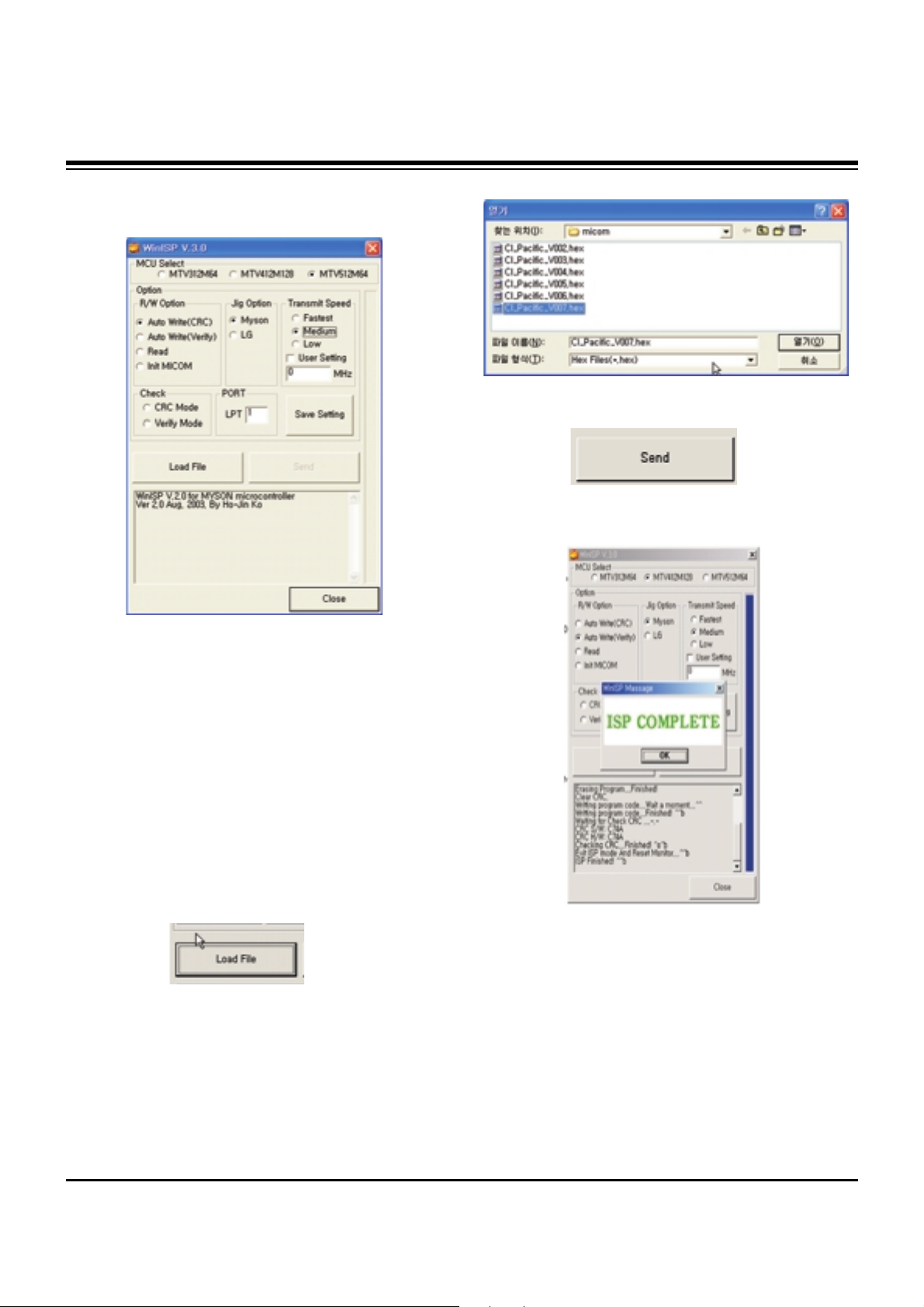
3. MICOM Download(Option)
3-1. Required Test Equipment
(1) JIG-LEVER TYPE for adjusting: 1EA
(2) PC & MONITOR: 2EA
(3) BOARD for INTERFACE: IIC & ISP BOARD: 2EA
(4) 15P D-SUB CABLE: 2EA
(5) Using the 12/15 line of D-SUB 15P
12-SDA/15-SCL
3-2. JIG Connection
3-3. Establishment Program
(1) Establish LGE Monitor Tools v1.1
(2) The program work and it is opened program window as
seen below.
Test Pattern 2min 30sec
Test Pattern 30sec
If you turn on a still screen more than 20 minutes (Especially
Digital pattern(13 CH), Cross Hatch Pattern), an afterimage
may occur in the black level part of the screen.
connection
to PC
connection
to PC
Page 6
- 6 -
ADJUSTMENT INSTRUCTIONS
(3) Click the first icon shown in fig.9. The window seen in
fig.10 should appear.
3-4. Set Method
(1) MCU Select: MTV512M64
(2) Option
R/W Option: Auto Write(Verity)
Jig Option: Myson
Transmit Speed: Medium
(3) Check: Just do it with blank micom.
(4) PORT
Chose Parallel Port (normal LPT1)
Attention: You must chose EPP when select Rom BIAS at
LPT
3-5. Download Method
(1) Click the Load File.
(2) Locate and select the correct file from your computer.
(*.hex).
(3) Click the Send.
(4) When you see (ISP COMPLETE) the download is
complete.
Page 7
- 7 -
ADJUSTMENT INSTRUCTIONS
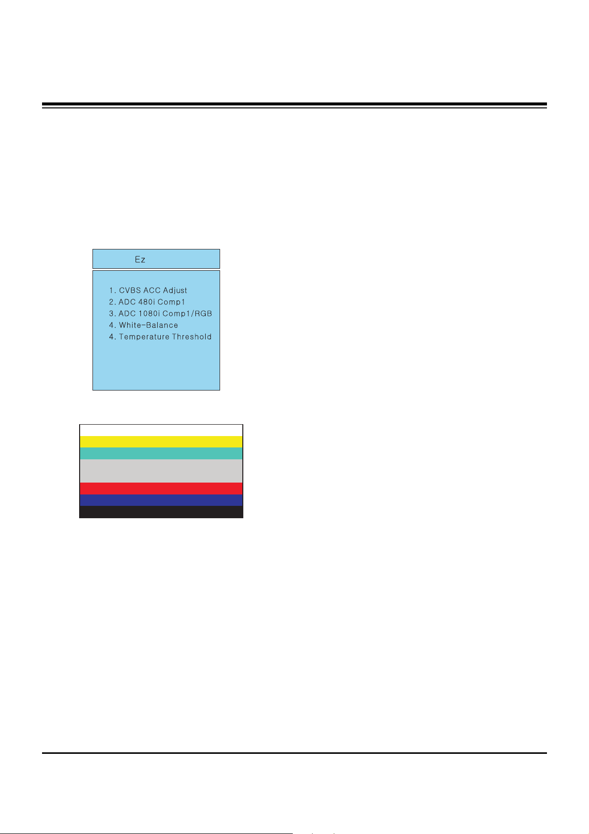
4. ADC-Set Adjustment
4-1. Synopsis
ADC-Set adjustment to set the black level and the Gain to
optimum.
4-2. Test Equipment
Service R/C, 801GF(802V, 802F, 802R) or MSPG925FA
Pattern Generator
(480i/1080i The Horizontal 100% Color Bar Pattern adjust to
within 0.7±0.1Vp-p)
4-3. Adjustment
(1) Select Component1 as the input with 100% Horizontal
Color Bar Pattern(HozTV31Bar) in 480i Mode
(2) After receiving signal for at least 1 second, press the ADJ
Key on the Service R/C to enter the ‘Ez - Adjust’ and select
the ‘2. ADC 480i Comp1’.
Pressing the Enter Key to adjust automatically.
(3) When the adjustment is over, 'MST3361 Component
Success’ is displayed. If the adjustment has errors,
'MST3361 Configuration Error’ is displayed.
(4) Select Component1 as the input with 100% Horizontal
Color Bar Pattern(HozTV31Bar) in 1080i Mode.
(5) After receiving signal for at least 1 second, press the ADJ
Key on the Service R/C to enter the ‘Ez - Adjust’ and select
the ‘3. ADC 1080i Comp1/RGB’.
Pressing the Enter Key to adjust automatically.
(6) When the adjustment is over, 'MST3361 Component
Success’ is displayed. If the adjustment has errors,
'MST3361 Configuration Error’ is displayed.
(7) After the Component MST3361 adjustment is over, convert
the RGB-DTV Mode and display Pattern.
When the adjustment is over, 'MST3361 RGB_DTV
Success’ is displayed.
(8) Readjust after confirming the case Pattern or adjustment
condition where the adjustment errors.
(9) After adjustment is complete, exit the adjustment mode by
pressing the ADJ KEY.
<Adjustment Mode>
<Adjustment Pattern: 480i/1080i 60Hz HozTV31Bar Pattern>
Page 8
- 8 -
ADJUSTMENT INSTRUCTIONS
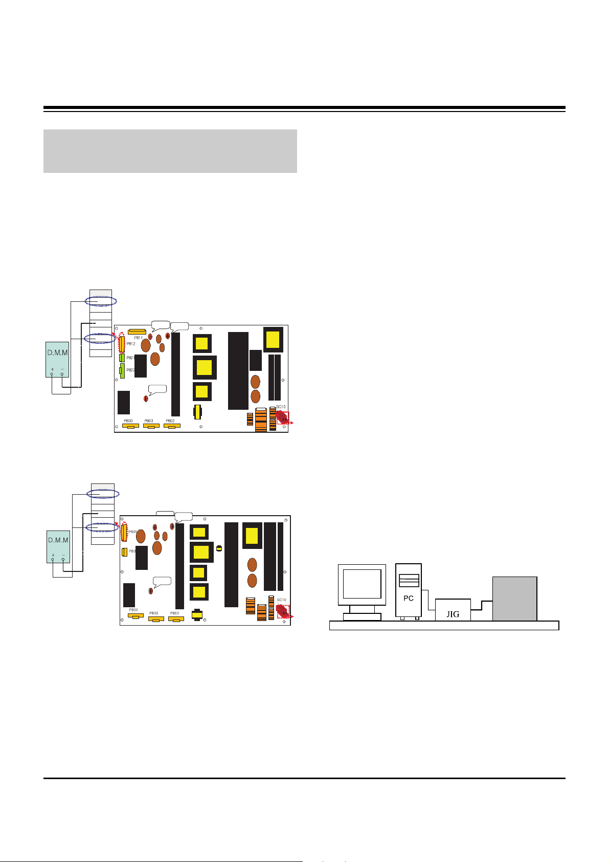
5. POWER PCB Assy Voltage
Adjustment
(Va, Vs Voltage Adjustment)
5-1. Test Equipment : D.M.M 1EA
5-2. Connection Diagram for Measuring
Refer to Fig 1.
5-3. Adjustment
(1) Va Adjustment
1) Connect + terminal of D.M.M to Va pin of P812(50”:
P805) and connect – terminal to GND pin of P812(50”:
P805).
2) Adjust VR901 voltage to match that of the label on the
Top/Right of the panel. (Deviation : ±0.5V)
(2) Vs Adjustment
1) Connect + terminal of D.M.M to Vs pin of P812(50”:
P805) and connect – terminal to GND pin of P812(50”:
P805).
2) Adjust RV401 voltage to match that of the label on the
Top/Right of the panel. (Deviation : ±0.5V)
6. EDID(The Extended Display
Identification Data)/DDC
(Display Data Channel) Download
This is the function that enables “Plug and Play".
6-1. HDMI EDID Data Input
(1) Required Test Equipment
1) PC, Jig for adjusting DDC. (PC serial to D-sub
Connection equipment)
2) S/W for writing DDC(EDID data write & read)
3) D-Sub cable
4) Jig for HDMI Cable connection
(2) Preparation for Adjustments &
Setting of Device
1) Set devices as below and turn on the PC and JIG.
2) Open S/W for writing DDC (EDID data write & read).
(operated in DOS mode)
Each PCB Assy must be checked by Check JIG Set before
assembly. (Especially, be careful Power PCB Assy which can
cause Damage to the PDP Module.)
111
VsAD J
VR951
VaADJ
VR901
3.3VADJ
VR22 1
T8
01
T9
01
T1
12
T5
01
L6
01
5V
GND
Va
GND
GND
NC
Vs
Vs
P811
111
VsAD J
VR951
VsAD J
VR951
VaADJ
VR901
VaADJ
VR901
3.3VADJ
VR22 1
T8
01
T9
01
T1
12
T5
01
L6
01
5V
GND
Va
GND
GND
NC
Vs
Vs
P811
<Fig. 1-1> Connection Diagram of Power Adjustment for
Measuring (Power Board): 42” XGA
VsADJ
VR951
5V
GND
Va
GND
GND
NC
Vs
Vs
P811
111
VaADJ
VR901
3.3VADJ
VR221
T8
01
T9
01
L8
51
T5
01
T1
12
L6
01
VsADJ
VR951
5V
GND
Va
GND
GND
NC
Vs
Vs
P811
111
VaADJ
VR901
VaADJ
VR901
3.3VADJ
VR221
T8
01
T9
01
L8
51
T5
01
T1
12
L6
01
<Fig. 1-2> Connection Diagram of Power Adjustment for
Measuring (Power Board): 50”
LCD TV SET
(or Digital Board)
<Fig. 2>
Page 9

- 9 -
ADJUSTMENT INSTRUCTIONS
6-2. EDID DATA for PA-63E
[42PX3D-UE: Z42PX3D]
: EDID for HDMI-1 (DDC (Display Data Channel) Data)
EDID Block 0 table =
0 1 2 3 4 5 6 7 8 9 A B C D E F
___________________________________________________
0 | 00 FF FF FF FF FF FF 00 1E 6D 01 00 01 01 01 01
10 | 00 10 01 03 80 5C 34 96 0A CF 74 A3 57 4C B0 23
20 | 09 48 4C 2F CE 00 31 40 45 40 61 40 01 01 01 01
30 | 01 01 01 01 01 01 64 19 00 40 41 00 26 30 18 88
40 | 36 00 C4 8E 21 00 00 1E 0E 1F 00 80 51 00 1E 30
50 | 40 80 37 00 C4 8E 21 00 00 1C 00 00 00 FD 00 38
60 | 4B 1F 3C 09 00 0A 20 20 20 20 02 20 00 00 00 FC
70 | 00 34 32 50 58 33 44 2D 55 45 0A 43 0A 20 01 5F
EDID Block 1 table =
0 1 2 3 4 5 6 7 8 9 A B C D E F
___________________________________________________
0 | 02 03 13 F1 44 84 05 03 02 23 15 07 50 65 03 0C
10 | 00 10 00 01 1D 00 72 51 D0 1E 20 6E 28 55 00 C4
20 | 8E 21 00 00 1E 01 1D 80 18 71 1C 16 20 58 2C 25
30 | 00 C4 8E 21 00 00 9E 8C 0A D0 8A 20 E0 2D 10 10
40 | 3E 96 00 C4 8E 21 00 00 18 8C 0A D0 8A 20 E0 2D
50 | 10 10 3E 96 00 13 8E 21 00 00 18 00 00 00 00 00
60 | 00 00 00 00 00 00 00 00 00 00 00 00 00 00 00 00
70 | 00 00 00 00 00 00 00 00 00 00 00 00 00 00 00 ED
: EDID for RGB-PC
EDID Block 0 table =
0 1 2 3 4 5 6 7 8 9 A B C D E F
___________________________________________________
0 | 00 FF FF FF FF FF FF 00 1E 6D 01 00 01 01 01 01
10 | 00 10 01 03 68 5C 34 96 0A CF 30 A3 57 4C B0 23
20 | 09 50 4E A1 08 00 01 01 01 01 01 01 01 01 01 01
30 | 01 01 01 01 01 01 64 19 00 40 41 00 26 30 18 88
40 | 36 00 98 07 32 00 00 18 0E 1F 00 80 51 00 1E 30
50 | 40 80 37 00 C4 8E 21 00 00 1C 66 21 50 B0 51 00
60 | 1B 30 40 70 36 00 C4 8E 21 00 00 1E 00 00 00 FC
70 | 00 34 32 50 58 33 44 2D 55 45 0A 20 20 20 00 21
[50PC3D-UE]
: EDID for HDMI-1 (DDC (Display Data Channel) Data)
EDID Block 0 table =
0 1 2 3 4 5 6 7 8 9 A B C D E F
___________________________________________________
0 | 00 FF FF FF FF FF FF 00 1E 6D 01 00 01 01 01 01
10 | 00 10 01 03 80 5C 34 96 0A CF 74 A3 57 4C B0 23
20 | 09 48 4C 2F CE 00 31 40 45 40 61 40 01 01 01 01
30 | 01 01 01 01 01 01 64 19 00 40 41 00 26 30 18 88
40 | 36 00 C4 8E 21 00 00 1E 0E 1F 00 80 51 00 1E 30
50 | 40 80 37 00 C4 8E 21 00 00 1C 00 00 00 FD 00 38
60 | 4B 1F 3C 09 00 0A 20 20 20 20 02 20 00 00 00 FC
70 | 00 34 32 50 58 33 44 2D 55 45 0A 43 0A 20 01 5F
EDID Block 1 table =
0 1 2 3 4 5 6 7 8 9 A B C D E F
___________________________________________________
0 | 02 03 13 F1 44 84 05 03 02 23 15 07 50 65 03 0C
10 | 00 10 00 01 1D 00 72 51 D0 1E 20 6E 28 55 00 C4
20 | 8E 21 00 00 1E 01 1D 80 18 71 1C 16 20 58 2C 25
30 | 00 C4 8E 21 00 00 9E 8C 0A D0 8A 20 E0 2D 10 10
40 | 3E 96 00 C4 8E 21 00 00 18 8C 0A D0 8A 20 E0 2D
50 | 10 10 3E 96 00 13 8E 21 00 00 18 00 00 00 00 00
60 | 00 00 00 00 00 00 00 00 00 00 00 00 00 00 00 00
70 | 00 00 00 00 00 00 00 00 00 00 00 00 00 00 00 ED
: EDID for HDMI-2 (DDC (Display Data Channel) Data)
EDID Block 0 table =
0 1 2 3 4 5 6 7 8 9 A B C D E F
___________________________________________________
0 | 00 FF FF FF FF FF FF 00 1E 6D 01 00 01 01 01 01
10 | 00 10 01 03 80 5C 34 96 0A CF 74 A3 57 4C B0 23
20 | 09 48 4C 2F CE 00 31 40 45 40 61 40 01 01 01 01
30 | 01 01 01 01 01 01 64 19 00 40 41 00 26 30 18 88
40 | 36 00 98 07 32 00 00 18 01 1D 80 18 71 1C 16 20
50 | 58 2C 25 00 C4 8E 21 00 00 9E 00 00 00 FC 00 34
60 | 32 50 58 33 44 2D 55 45 0A 43 0A 20 00 00 00 FD
70 | 00 38 4B 1F 3C 09 00 0A 20 20 20 20 20 20 01 67
EDID Block 1 table =
0 1 2 3 4 5 6 7 8 9 A B C D E F
___________________________________________________
0 | 02 03 13 F1 44 84 05 03 02 23 15 07 50 65 03 0C
10 | 00 20 00 8C 0A D0 8A 20 E0 2D 10 10 3E 96 00 C4
20 | 8E 21 00 00 18 8C 0A D0 8A 20 E0 2D 10 10 3E 96
30 | 00 13 8E 21 00 00 18 00 00 00 00 00 00 00 00 00
40 | 00 00 00 00 00 00 00 00 00 00 00 00 00 00 00 00
50 | 00 00 00 00 00 00 00 00 00 00 00 00 00 00 00 00
60 | 00 00 00 00 00 00 00 00 00 00 00 00 00 00 00 00
70 | 00 00 00 00 00 00 00 00 00 00 00 00 00 00 00 7B
: EDID for RGB-PC
EDID Block 0 table =
0 1 2 3 4 5 6 7 8 9 A B C D E F
___________________________________________________
0 | 00 FF FF FF FF FF FF 00 1E 6D 01 00 01 01 01 01
10 | 00 10 01 03 68 5C 34 96 0A CF 30 A3 57 4C B0 23
20 | 09 50 4E A1 08 00 01 01 01 01 01 01 01 01 01 01
30 | 01 01 01 01 01 01 64 19 00 40 41 00 26 30 18 88
40 | 36 00 98 07 32 00 00 18 0E 1F 00 80 51 00 1E 30
50 | 40 80 37 00 C4 8E 21 00 00 1C 66 21 50 B0 51 00
60 | 1B 30 40 70 36 00 C4 8E 21 00 00 1E 00 00 00 FC
70 | 00 34 32 50 58 33 44 2D 55 45 0A 20 20 20 00 21
Page 10
- 10 -
ADJUSTMENT INSTRUCTIONS
[60PC1D-UE]
: EDID for HDMI-1 (DDC (Display Data Channel) Data)
EDID Block 0 table =
0 1 2 3 4 5 6 7 8 9 A B C D E F
___________________________________________________
0 | 00 FF FF FF FF FF FF 00 1E 6D 01 00 01 01 01 01
10 | 00 10 01 03 80 5C 34 96 0A CF 74 A3 57 4C B0 23
20 | 09 48 4C 2F CE 00 31 40 45 40 61 40 01 01 01 01
30 | 01 01 01 01 01 01 64 19 00 40 41 00 26 30 18 88
40 | 36 00 C4 8E 21 00 00 1E 0E 1F 00 80 51 00 1E 30
50 | 40 80 37 00 C4 8E 21 00 00 1C 00 00 00 FD 00 38
60 | 4B 1F 3C 09 00 0A 20 20 20 20 02 20 00 00 00 FC
70 | 00 34 32 50 58 33 44 2D 55 45 0A 43 0A 20 01 5F
EDID Block 1 table =
0 1 2 3 4 5 6 7 8 9 A B C D E F
___________________________________________________
0 | 02 03 13 F1 44 84 05 03 02 23 15 07 50 65 03 0C
10 | 00 10 00 01 1D 00 72 51 D0 1E 20 6E 28 55 00 C4
20 | 8E 21 00 00 1E 01 1D 80 18 71 1C 16 20 58 2C 25
30 | 00 C4 8E 21 00 00 9E 8C 0A D0 8A 20 E0 2D 10 10
40 | 3E 96 00 C4 8E 21 00 00 18 8C 0A D0 8A 20 E0 2D
50 | 10 10 3E 96 00 13 8E 21 00 00 18 00 00 00 00 00
60 | 00 00 00 00 00 00 00 00 00 00 00 00 00 00 00 00
70 | 00 00 00 00 00 00 00 00 00 00 00 00 00 00 00 ED
: EDID for HDMI-2 (DDC (Display Data Channel) Data)
EDID Block 0 table =
0 1 2 3 4 5 6 7 8 9 A B C D E F
___________________________________________________
0 | 00 FF FF FF FF FF FF 00 1E 6D 01 00 01 01 01 01
10 | 00 10 01 03 80 5C 34 96 0A CF 74 A3 57 4C B0 23
20 | 09 48 4C 2F CE 00 31 40 45 40 61 40 01 01 01 01
30 | 01 01 01 01 01 01 64 19 00 40 41 00 26 30 18 88
40 | 36 00 98 07 32 00 00 18 01 1D 80 18 71 1C 16 20
50 | 58 2C 25 00 C4 8E 21 00 00 9E 00 00 00 FC 00 34
60 | 32 50 58 33 44 2D 55 45 0A 43 0A 20 00 00 00 FD
70 | 00 38 4B 1F 3C 09 00 0A 20 20 20 20 20 20 01 67
EDID Block 1 table =
0 1 2 3 4 5 6 7 8 9 A B C D E F
___________________________________________________
0 | 02 03 13 F1 44 84 05 03 02 23 15 07 50 65 03 0C
10 | 00 20 00 8C 0A D0 8A 20 E0 2D 10 10 3E 96 00 C4
20 | 8E 21 00 00 18 8C 0A D0 8A 20 E0 2D 10 10 3E 96
30 | 00 13 8E 21 00 00 18 00 00 00 00 00 00 00 00 00
40 | 00 00 00 00 00 00 00 00 00 00 00 00 00 00 00 00
50 | 00 00 00 00 00 00 00 00 00 00 00 00 00 00 00 00
60 | 00 00 00 00 00 00 00 00 00 00 00 00 00 00 00 00
70 | 00 00 00 00 00 00 00 00 00 00 00 00 00 00 00 7B
: EDID for RGB-PC
EDID Block 0 table =
0 1 2 3 4 5 6 7 8 9 A B C D E F
___________________________________________________
0 | 00 FF FF FF FF FF FF 00 1E 6D 01 00 01 01 01 01
10 | 00 10 01 03 68 5C 34 96 0A CF 30 A3 57 4C B0 23
20 | 09 50 4E A1 08 00 01 01 01 01 01 01 01 01 01 01
30 | 01 01 01 01 01 01 64 19 00 40 41 00 26 30 18 88
40 | 36 00 98 07 32 00 00 18 0E 1F 00 80 51 00 1E 30
50 | 40 80 37 00 C4 8E 21 00 00 1C 66 21 50 B0 51 00
60 | 1B 30 40 70 36 00 C4 8E 21 00 00 1E 00 00 00 FC
70 | 00 34 32 50 58 33 44 2D 55 45 0A 20 20 20 00 21
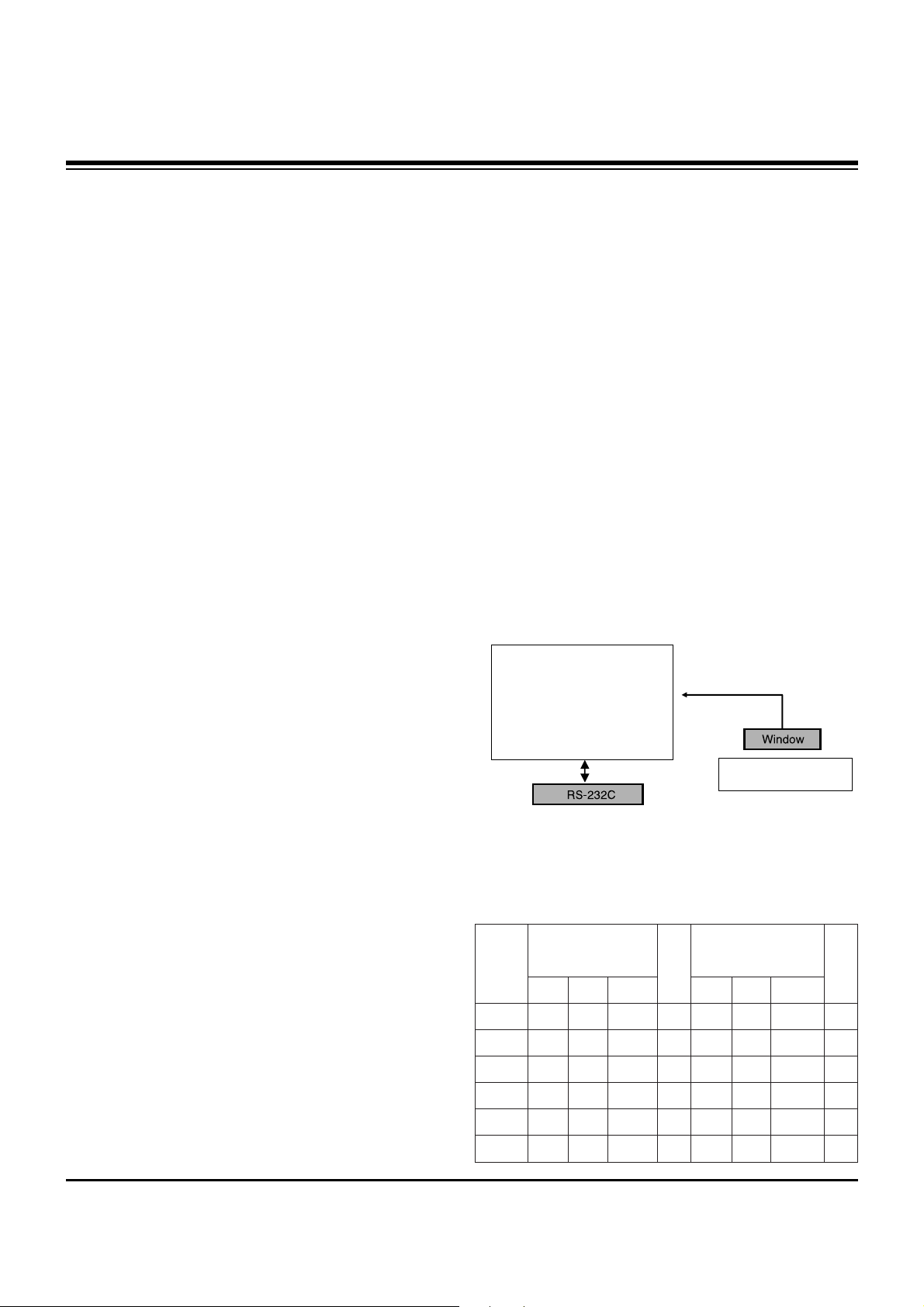
7. Adjustment of White Balance
7-1. Required Equipment
(1) Color analyzer (CA-100 or similar product)
(2) Automatic adjustor (with automatic adjustment necessity
and the RS-232C communication being possible)
(3) Pattern Generator(MSPG-925FA): DVI Output
7-2. Connection Diagram of Equipment
for Measuring (Automatic Adjustment)
[
RS-232C Command (Automatic Adjustment)
[42PX3D-UE: Z42PX3D]
Full White Pattern
Digital RGB
PDP MONITOR
COLOR
ANALYZER
TYPE; CA-100
MSPG-925FA
<Fig. 3> Connection Diagram of Automatic Adjustment
R Gain
G Gain
B Gain
R Cut
G Cut
B Cut
Jg
Jh
Ji
Cool
Ja
Jb
Jc
Mid
RS-232C COMMAND
[CMD ID DATA]
CENTER
(DEFAULT)(Decimal)
Jd
Je
Jf
00
00
00
ff
ff
ff
7f
7f
7f
Warm
Min
Max
(Deci
mal)
bd
ac
c0
41
40
42
Cool
c0
a9
b1
3f
40
41
Mid
c0
8f
68
40
40
45
Warm
Page 11

- 11 -
ADJUSTMENT INSTRUCTIONS
[50PC3D-UE]
7-3. Adjustment of White Balance
O
Calibrate of the CA-100, then attach sensor to PDP module
surface when you adjust.
O
Manual adjustment is also possible by the following sequence.
(1) Enter ‘Ez - Adjust’ by pressing ADJ KEY on the Service
Remote Control.
(2) Select "9. WHITE PATTERN" using CH +/- Key and HEAT
RUN at least 30 minutes by pressing the ENTER Key.
(3) Receive the Window pattern signal from Digital Pattern
Generator.
(AV Input: connect the ‘HDMI’, Digital Pattern Generator input
Pattern => Model: 217, pattern: 6, opt: 106.64.48.1.216)
(4) After attaching sensor to center of screen, select ‘6. White-
Balance’ of ‘Ez - Adjust’ by pressing the ADJ KEY on the
Service R/C. Then enter adjustment mode by pressing the
Right KEY (
G
) .
[42PX3D-UE: Z42PX3D]
1) Adjust the Hight Light using G Gain/R Gain(Cool).
(B Gain: 192, R-Cut/G-Cut/B-Cut: 65/64/66 Fix.)
2) Adjust the Hight Light using G Gain/B Gain(Medium).
(R Gain: 192, R-Cut/G-Cut/B-Cut: 63/64/65 Fix.)
3) Adjust the Hight Light using G Gain/B Gain(Warm).
(R Gain: 192, R-Cut/G-Cut/B-Cut: 64/64/69 Fix.)
[50PC3D-UE]
1) Adjust the Hight Light using G Gain/B Gain(Cool).
(R Gain: 192, R-Cut/G-Cut/B-Cut: 63/61/69 Fix.)
2) Adjust the Hight Light using G Gain/B Gain(Medium).
(R Gain: 192, R-Cut/G-Cut/B-Cut: 64/61/70 Fix.)
3) Adjust the Hight Light using G Gain/B Gain(Warm).
(R Gain: 192, R-Cut/G-Cut/B-Cut: 61/61/70 Fix.)
(6) Adjust using Volume +/- KEY.
(7) After adjustment is complete, exit the adjustment mode by
pressing the ENTER(
V) KEY => ADJ KEY.
High Level: 216gray
[Cool]
X; 0.278±0.002 Y; 0.279±0.002
Color temperature: 11000°K±1500°K
dUV: -3dUV
[Medium]
X; 0.287±0.002 Y; 0.289±0.002
Color temperature: 9300°K±1500°K
dUV: -3dUV
[Warm]
X; 0.315±0.002 Y; 0.316±0.002
Color temperature: 6500°K±1500°K
dUV: -3dUV
R Gain
G Gain
B Gain
R Cut
G Cut
B Cut
Jg
Jh
Ji
Cool
Ja
Jb
Jc
Mid
RS-232C COMMAND
[CMD ID DATA]
CENTER
(DEFAULT)(Decimal)
Jd
Je
Jf
00
00
00
ff
ff
ff
7f
7f
7f
Warm
Min
Max
(Deci
mal)
c0
a8
b4
3f
3d
45
Cool
c0
a6
9d
40
3d
46
Mid
c0
85
58
3d
3d
46
Warm
Page 12

- 12 -
PRINTED CIRCUIT BOARDS
MAIN(TOP)
Page 13

- 13 -
PRINTED CIRCUIT BOARDS
MAIN(BOTTOM)
Page 14

- 14 -
PRINTED CIRCUIT BOARDS
CONTROL
SIDE A/V(TOP)
PRE-AMP
SIDE A/V(BOTTOM)
Page 15

- 15 -
BLOCK DIAGRAM
Page 16

- 16 -
EXPLODED VIEW
300
121
560
120
570
305
303
302
301
304
200
580
201
202
203
204
240
400
430
431
250
205
206
208
101
207
600
602
601
590
501
502
520
Page 17

- 17 -
EXPLODED VIEW PARTS LIST
101 5900904001A Fan Module,1.7KRPM DC 12V 250UA 3W 50HZ
120 EAB30829601 Speaker,Woofer g2060102 ND 15W 8OHM 82DB 100HZ 240 X 57 X 49 LUG MACOM
121 EAB30826001 Speaker,Tweeter D013d03k1400 ND 15W 8OHM 85DB 0HZ 88 X 38.3 X 10 LUG
200 EAJ34777301 PDP,Module-XGA PDP50X40000.ADLGB XGA 50INCH 1365X768 16/9 PDP DIVISION
201 6871QCH083A PCB Assembly,CTRL Board CTRL ASS’Y 50 CTRL PDP DIVISION
202 6871QDH115A PCB Assembly,Y DRIVE TOP YDRV ASS’Y 50 X4 PDP DIVISION
203 6871QDH116A PCB Assembly,Y DRIVE BOTTOM YDRV ASS’Y 50 X4 YDRV BTM PDP DIVISION
204 6871QLH063A PCB Assembly,X_LEFT BOARD XRLT ASS’Y 50 X4 PDP DIVISION
205 6871QXH034A PCB Assembly,X_CENTER BOARD XRCT ASS’Y 50 X4 PDP DIVISION
206 6871QRH073A PCB Assembly,X_RIGHT BOARD XRRT ASS’Y 50 X4 PDP DIVISION
207 6871QYH061A PCB Assembly,Y_SUS BOARD YSUS ASS’Y 50 X4 2 LAYER PDP DIVISION
208 6871QZH065A PCB Assembly,Z_SUS BOARD ZSUS ASS’Y 50 X4 2 LAYER PDP DIVISION
240 4980900101C Supporter ASSY,AL SKD
250 4980900102C Supporter ASSY,AL VERTICAL L SKD
300 ACQ30250001 Cover Assembly,50PC3D-UD . 50 LG ERS
301 4980900103B Supporter,FILTER AL 50PC3D-UD.SUSULLJR
302 4980900104B Supporter,FILTER AL 50PC3D-UD.SUSULLJR BOTTOM
303 4980900105B Supporter,FILTER AL 50PC3D-UD.SUSULLJR RIGHT
304 4980900106B Supporter,FILTER AL 50PC3D-UD.SUSULLJR LEFT
305 5230V00025C Filter,PRINTING TOP 50PDP Glass ∏µ® ¿˚øÎ LG CHEMICAL GLASS FILTER (38%)
400 3809900102M Cover Assembly,50PC3D-UE PA63E 50 BCM CKD
430 3501900004K Base Assembly,STAND 50PC3D-UD PA61A SKD
431 35509K0101F Cover,MOLD HIPS 51SF 50pc1 HIPS 51SF ckd
501 3301900089Q Plate Assembly,AV 50PC3D-UE AF044C(BCM)
3301900089S Plate Assembly,AV 50PC3D-UE SKD BCM
502 3301900094V Plate Assembly,50PC3D-UE AF044C(BCM)
3301900094W Plate Assembly,50PC3D-UE AF044C(BCM)
520 EBR31360004 PCB Assembly,Main PA63E 50PC3D-UE SUSYLJR Broadcom X4
EBR31360005 PCB Assembly,Main PA63E 50PC3D-UE KUSYLMR Broadcom X4
560 68719SM157B PCB Assembly,Sub PA51D 50PC3D-UD SUSLLJR -
68719SM157D PCB Assembly,Sub PA51D 42PC3D-UD KUSLLMR
570 EBR32645102 PCB Assembly,SUB M.I PA63E 50PC3D-UE .SUSLLJR PREAMP+LED
EBR32645103 PCB Assembly,SUB M.I PA63E 50PC3D-UE .KUSLLMR PREAMP+LED
580 6709900020B Power Supply Assembly,50INCH UNIFAICATION PSU PDP LGIT PA61A 530W 50PB2DR
590 6200J000115 Filter,AC Line IJ-N06CESL1 5.3mH 250VAC 6A 0.22uF 1000pF
600 68719SM156A PCB Assembly,Sub PA51D 50PC3D-UD AUSLLAX -
68719SM156B PCB Assembly,Sub PA51D 50PC3D-UD KUSLLMR -
601 4811900021A Bracket Assembly,SIDE AV 42PC3D-UD PA51D NORTH AMERICA
602 48149V0003B Plate,PRESS SPTE T0.3 SIDE AV 50PC1R
No.
Part No.
Description
Page 18

- 18 -
REPLACEMENT PARTS LIST
LOCA. NO PART NO DESCRIPTION
Q4005
Q4006
Q4007
Q4008
Q4009
Q4010
Q5004
Q5005
Q5006
Q5007
Q5009
Q5010
Q5011
Q5012
Q5013
Q5014
Q5015
Q5016
Q5017
Q7002
Q7003
Q7005
Q7009
Q7011
Q7012
Q7013
D4001
D4002
D4003
D4005
D4006
D4007
D4008
D5001
D5002
D5015
D7001
D7002
LD101
ZD1001
C100
C1001
C1007
C1008
0TRIY80001A
0TRIY80001A
0TRIY80001A
0TRIY80001A
0TRIY80001A
0TRIY80001A
0TRIH80002A
0TRIH80002A
0TRIY80001A
0TRIY80001A
0TRIY80001A
0TRIY80001A
0TRIY80001A
0TRIY80001A
0TRIY80001A
0TRIY80001A
0TRIY80001A
0TRIY80001A
0TRIY80001A
0TR102009AJ
0TR102009AJ
0TRIY80001A
0TRIY80001A
0TRIY80001A
0TR102009AJ
0TR102009AJ
0DRSE00038A
0DRSE00038A
0DSIH00028A
0DSIH00028A
0DL233309AC
0DR340009AA
0DS226009AA
0DSIH00028A
0DSIH00028A
0DZRM00178A
0DSIH00028A
0DSIH00028A
0DL200000CA
0DZDI00078A
0CH5331K416
0CE107WF6DC
0CK103BH56A
0CK104BF56A
2SC3052 NPN 6V 50V 50V 200MA
2SC3052 NPN 6V 50V 50V 200MA
2SC3052 NPN 6V 50V 50V 200MA
2SC3052 NPN 6V 50V 50V 200MA
2SC3052 NPN 6V 50V 50V 200MA
2SC3052 NPN 6V 50V 50V 200MA
2SA1530A-T112-1R PNP -6V -60
2SA1530A-T112-1R PNP -6V -60
2SC3052 NPN 6V 50V 50V 200MA
2SC3052 NPN 6V 50V 50V 200MA
2SC3052 NPN 6V 50V 50V 200MA
2SC3052 NPN 6V 50V 50V 200MA
2SC3052 NPN 6V 50V 50V 200MA
2SC3052 NPN 6V 50V 50V 200MA
2SC3052 NPN 6V 50V 50V 200MA
2SC3052 NPN 6V 50V 50V 200MA
2SC3052 NPN 6V 50V 50V 200MA
2SC3052 NPN 6V 50V 50V 200MA
2SC3052 NPN 6V 50V 50V 200MA
KRC102S NPN 30V 0V 50V 100MA
KRC102S NPN 30V 0V 50V 100MA
2SC3052 NPN 6V 50V 50V 200MA
2SC3052 NPN 6V 50V 50V 200MA
2SC3052 NPN 6V 50V 50V 200MA
KRC102S NPN 30V 0V 50V 100MA
KRC102S NPN 30V 0V 50V 100MA
SDC15 1.3V 14.3VTO16.4V 21.2
SDC15 1.3V 14.3VTO16.4V 21.2
MC2838-T112-1 1.2V 75V 300MA
MC2838-T112-1 1.2V 75V 300MA
LED,Chip SAM2333
MBRS340 525MV 40V 4A 0SEC 0F
KDS226 1.2V 85V 300MA 2A 4NS
MC2838-T112-1 1.2V 75V 300MA
MC2838-T112-1 1.2V 75V 300MA
Zener,UDZS5.1B 5.1V
MC2838-T112-1 1.2V 75V 300MA
MC2838-T112-1 1.2V 75V 300MA
LED,DIP SAM5670(DL-2LRG)
Zener,BZT52C3V3S-F
0805N331J500LT 330pF 5% 50V
MVK6.3TP16VC100M 100uF 20% 1
C1005X7R1E103KT- 10nF 10% 25
C1005X7R104KET 100nF 10% 16V
LOCA. NO PART NO DESCRIPTION
IC1001
IC2002
IC2003
IC3001
IC4001
IC4002
IC4003
IC4004
IC4006
IC4007
IC4008
IC4010
IC4011
IC4012
IC4013
IC4014
IC4016
IC4017
IC5001
IC5002
IC5003
IC5004
IC6003
IC6004
IC6005
IC6006
IC7001
IC7002
IC7004
IC7005
IC7008
IC7010
IC7012
IC7013
IC7015
IC7016
IC7017
Q1001
Q1002
Q101
Q102
Q4001
Q4003
Q4004
0IPRP00702A
0IMMRHY057E
0IMMRHY057E
EAN30267601
0IPRP00009A
0IPRP00538A
0IPMGA0010A
0IKE702900G
0IPRPFA015B
0ISTLPH026A
0IPMGS1006B
0IKE702900G
0IMCRRH001A
0IMCRAL021A
0IMCRSH001A
0IMCRAL006A
0IMCRFA010A
EAN31513601
EAN30744301
EAN30744401
0ISO206900A
0IPRPCI016A
0IMI623200B
0IMCRTH002A
0IPMGKE032A
0IPMGKE032A
0ICB533100A
0ISTL00029A
0IPRP00696A
0IMMRCS012B
0IPH740800H
0IMMRAL014D
0IMMRAL014D
0IMMRAL014D
0IPRP00623A
0IPRP00623A
0IPRP00700A
0TRIY80001A
0TRIY80001A
0TR387500AA
0TR387500AA
0TRIH80002A
0TRIY80001A
0TRIY80001A
BCM3550KPB5G 1.14VTO1.26V
HY5DU561622ETP-D43 256MBIT
HY5DU561622ETP-D43 256MBIT
TPS2052BDRG4 2.7TO5.5 3MSE
ICL3232CBNZ 3VTO5.5V - SSO
FSA1156P6X-NL 1.65TO5.5V 4
AZ1117H-3.3 4.75TO10V 3.3V
KIA7029AF -0.3TO15V 2.9V 5
FMS6400CS1X,LF 4.75VTO5.25
74LVC14APW 1.2TO3.6V 0.01m
SC1566I5M25TRT 2.2V~5.5V 1
KIA7029AF -0.3TO15V 2.9V 5
BA033FP-E2 4.3TO25V 3.3V 1
AT24C512W-10SU-2.7 512KBIT
PQ05DZ1U 6TO16V 5V 8W D2PA
AT24C16AN-10SU-2.7 16KBIT
KA7809R 11.5TO24V 9V 150W
SC4519STRT 2.6V to 16V 0.8
MM1732XVBE 4.5TO9.5 50NSEC
MM1731XVBE 4.0TO9.5 50NSEC
CXA2069Q 8.5TO9.5V - - 1.3
CS4344-CZZR 4.75TO5.25V 3T
M62320FP(SOP) 4.5TO5.5V 0.
THC63LVD103 3VTO3.6V 1W TQ
KIA78R09F 10TO25V 9V 8W DP
KIA78R09F 10TO25V 9V 8W DP
CS5331A-KSR 4.75TO5.25V 48
MC33078DR2G +-5TO+-18V 2mV
MST3361M-LF-110 3.3V_2.5V
CAT24WC08W-T(MST3000) 8KBI
74F08D 4.5TO5.5V 12.9mA AN
AT24C02BN-10SU-1.8 2KBIT 2
AT24C02BN-10SU-1.8 2KBIT 2
AT24C02BN-10SU-1.8 2KBIT 2
CM2021-00TR 1VTO5.5V,0VTO0
CM2021-00TR 1VTO5.5V,0VTO0
TPA3100D2PHPR 10TO26V . .
2SC3052 NPN 6V 50V 50V 200MA
2SC3052 NPN 6V 50V 50V 200MA
2SC3875S(ALY) NPN 5V 60V 50V
2SC3875S(ALY) NPN 5V 60V 50V
2SA1530A-T112-1R PNP -6V -60
2SC3052 NPN 6V 50V 50V 200MA
2SC3052 NPN 6V 50V 50V 200MA
IC
RUN DATE : 2007.8.17
For Capacitor & Resistors, the
charactors at 2nd and 3rd digit
in the P/No. means as follows;
CC, CX, CK, CN : Ceramic
CQ : Polyestor
CE : Electrolytic
RD : Carbon Film
RS : Metal Oxide Film
RN : Metal Film
RF : Fusible
TRANSISTOR
DIODE
CAPACITOR
Page 19

- 19 -
LOCA. NO PART NO DESCRIPTION
C1009
C101
C101
C1010
C1011
C1012
C1016
C1017
C1018
C1019
C102
C1020
C1021
C1022
C1024
C1025
C1027
C1028
C1029
C103
C1030
C1032
C1033
C1034
C1036
C1037
C1038
C1039
C104
C1040
C1041
C1042
C1043
C1044
C1045
C1046
C105
C1050
C1051
C1052
C1053
C1054
C1055
C1056
C1057
C1058
C1059
C1060
C1061
C1062
C1063
0CK104BF56A
0CH5331K416
0CC101CK41A
0CK104BF56A
0CK104BF56A
0CK105CD56A
0CK475CC94A
0CK104BF56A
0CK104BF56A
0CK104BF56A
0CC330CK41A
0CK104BF56A
0CK104BF56A
0CK104BF56A
0CK104BF56A
0CK103BH56A
0CK104BF56A
0CK475CC94A
0CK104BF56A
0CE4763F618
0CK104BF56A
0CK104BF56A
0CK104BF56A
0CK475CC94A
0CK103BH56A
0CK103BH56A
0CK103BH56A
0CK104BF56A
0CE4763F618
0CK104BF56A
0CK475CC94A
0CK104BF56A
0CK104BF56A
0CK104BF56A
0CK104BF56A
0CK104BF56A
0CE4763F618
0CK103BH56A
0CK104BF56A
0CK104BF56A
0CK104BF56A
0CK103CK56A
0CK103CK56A
0CK103CK56A
0CK103CK56A
0CH2122K516
0CH2122K516
0CH2122K516
0CH2122K516
0CK104BF56A
0CK104BF56A
C1005X7R104KET 100nF 10% 16V
0805N331J500LT 330pF 5% 50V
C1608C0G1H101JT 100pF 5% 50V
C1005X7R104KET 100nF 10% 16V
C1005X7R104KET 100nF 10% 16V
C1608X7R1A105KT 1uF 10% 10V
C1608Y5V0J475ZT 4.7uF -20TO+
C1005X7R104KET 100nF 10% 16V
C1005X7R104KET 100nF 10% 16V
C1005X7R104KET 100nF 10% 16V
C1608C0G1H330JT 33pF 5% 50V
C1005X7R104KET 100nF 10% 16V
C1005X7R104KET 100nF 10% 16V
C1005X7R104KET 100nF 10% 16V
C1005X7R104KET 100nF 10% 16V
C1005X7R1E103KT- 10nF 10% 25
C1005X7R104KET 100nF 10% 16V
C1608Y5V0J475ZT 4.7uF -20TO+
C1005X7R104KET 100nF 10% 16V
ESF476M016T1A5E05G 47uF 20%
C1005X7R104KET 100nF 10% 16V
C1005X7R104KET 100nF 10% 16V
C1005X7R104KET 100nF 10% 16V
C1608Y5V0J475ZT 4.7uF -20TO+
C1005X7R1E103KT- 10nF 10% 25
C1005X7R1E103KT- 10nF 10% 25
C1005X7R1E103KT- 10nF 10% 25
C1005X7R104KET 100nF 10% 16V
ESF476M016T1A5E05G 47uF 20%
C1005X7R104KET 100nF 10% 16V
C1608Y5V0J475ZT 4.7uF -20TO+
C1005X7R104KET 100nF 10% 16V
C1005X7R104KET 100nF 10% 16V
C1005X7R104KET 100nF 10% 16V
C1005X7R104KET 100nF 10% 16V
C1005X7R104KET 100nF 10% 16V
ESF476M016T1A5E05G 47uF 20%
C1005X7R1E103KT- 10nF 10% 25
C1005X7R104KET 100nF 10% 16V
C1005X7R104KET 100nF 10% 16V
C1005X7R104KET 100nF 10% 16V
0603B103K500CT 10nF 10% 50V
0603B103K500CT 10nF 10% 50V
0603B103K500CT 10nF 10% 50V
0603B103K500CT 10nF 10% 50V
0805B122K500CT 1.2nF 10% 50V
0805B122K500CT 1.2nF 10% 50V
0805B122K500CT 1.2nF 10% 50V
0805B122K500CT 1.2nF 10% 50V
C1005X7R104KET 100nF 10% 16V
C1005X7R104KET 100nF 10% 16V
LOCA. NO PART NO DESCRIPTION
C1064
C1065
C2001
C2002
C2003
C2004
C2005
C2006
C2007
C2008
C2009
C2010
C2011
C2012
C2013
C2014
C2015
C2016
C2017
C2018
C2019
C2020
C2021
C2022
C2023
C2024
C2025
C2026
C2027
C2028
C2029
C2030
C2031
C2032
C2033
C2034
C3005
C3007
C3008
C3012
C3013
C3014
C3015
C3016
C3017
C3018
C3019
C3020
C3021
C3022
C3023
0CK103BH56A
0CK475CC94A
0CK104BF56A
0CK104BF56A
0CE107WF6DC
0CE107WF6DC
0CK475CC94A
0CK104BF56A
0CK104BF56A
0CK104BF56A
0CK103BH56A
0CK104BF56A
0CK103BH56A
0CK473CH56A
0CK473CH56A
0CK104BF56A
0CK104BF56A
0CK272CK46A
0CK272CK46A
0CK102BK56A
0CK102BK56A
0CK102BK56A
0CC471CK41A
0CC471CK41A
0CK103BH56A
0CK102BK56A
0CK102BK56A
0CK104BF56A
0CK105CD56A
0CC471CK41A
0CK105CD56A
0CC471CK41A
0CK105CD56A
0CK105CD56A
0CC471CK41A
0CC471CK41A
0CK475CC94A
0CC080CK11A
0CC080CK11A
0CC150CK41A
0CC150CK41A
0CK104BF56A
0CK104BF56A
0CK104BF56A
0CK104BF56A
0CK103BH56A
0CK103BH56A
0CE336WD6D8
0CE336WD6D8
0CK106DC67A
0CK106DC67A
C1005X7R1E103KT- 10nF 10% 25
C1608Y5V0J475ZT 4.7uF -20TO+
C1005X7R104KET 100nF 10% 16V
C1005X7R104KET 100nF 10% 16V
MVK6.3TP16VC100M 100uF 20% 1
MVK6.3TP16VC100M 100uF 20% 1
C1608Y5V0J475ZT 4.7uF -20TO+
C1005X7R104KET 100nF 10% 16V
C1005X7R104KET 100nF 10% 16V
C1005X7R104KET 100nF 10% 16V
C1005X7R1E103KT- 10nF 10% 25
C1005X7R104KET 100nF 10% 16V
C1005X7R1E103KT- 10nF 10% 25
C1608X7R1E473KT 47nF 10% 25V
C1608X7R1E473KT 47nF 10% 25V
C1005X7R104KET 100nF 10% 16V
C1005X7R104KET 100nF 10% 16V
0603B272J500CT 2.7nF 10% 50V
0603B272J500CT 2.7nF 10% 50V
0402B102K500CT 1nF 10% 50V X
0402B102K500CT 1nF 10% 50V X
0402B102K500CT 1nF 10% 50V X
C1608C0G1H471JT 470pF 5% 50V
C1608C0G1H471JT 470pF 5% 50V
C1005X7R1E103KT- 10nF 10% 25
0402B102K500CT 1nF 10% 50V X
0402B102K500CT 1nF 10% 50V X
C1005X7R104KET 100nF 10% 16V
C1608X7R1A105KT 1uF 10% 10V
C1608C0G1H471JT 470pF 5% 50V
C1608X7R1A105KT 1uF 10% 10V
C1608C0G1H471JT 470pF 5% 50V
C1608X7R1A105KT 1uF 10% 10V
C1608X7R1A105KT 1uF 10% 10V
C1608C0G1H471JT 470pF 5% 50V
C1608C0G1H471JT 470pF 5% 50V
C1608Y5V0J475ZT 4.7uF -20TO+
C1608C0G1H080DT 8pF 0.5PF 50
C1608C0G1H080DT 8pF 0.5PF 50
C1608C0G1H150JT 15pF 5% 50V
C1608C0G1H150JT 15pF 5% 50V
C1005X7R104KET 100nF 10% 16V
C1005X7R104KET 100nF 10% 16V
C1005X7R104KET 100nF 10% 16V
C1005X7R104KET 100nF 10% 16V
C1005X7R1E103KT- 10nF 10% 25
C1005X7R1E103KT- 10nF 10% 25
RC1A336M05005VR 33uF 20% 10V
RC1A336M05005VR 33uF 20% 10V
JMK212JB106MG-T 10uF 20% 6.3
JMK212JB106MG-T 10uF 20% 6.3
REPLACEMENT PARTS LIST
Page 20

- 20 -
LOCA. NO PART NO DESCRIPTION
C3024
C3025
C3026
C3027
C3028
C3029
C3030
C3031
C3032
C3033
C3034
C3035
C3036
C3037
C3038
C3039
C3040
C3041
C3042
C3043
C3044
C3045
C3046
C3047
C3048
C3049
C3050
C3051
C3052
C3053
C3054
C3055
C3056
C3057
C3058
C3059
C3060
C3061
C3062
C3063
C3064
C3065
C3066
C3067
C3068
C4001
C4002
C4003
C4004
C4005
C4006
0CK104BF56A
0CK102BK56A
0CK103BH56A
0CK475CC94A
0CK104BF56A
0CK103BH56A
0CK103BH56A
0CK102BK56A
0CK475CC94A
0CK104BF56A
0CH8106F691
0CK104BF56A
0CK103BH56A
0CH8106F691
0CK102BK56A
0CK475CC94A
0CK105CD56A
0CK104BF56A
0CK103BH56A
0CK102BK56A
0CK104BF56A
0CK103BH56A
0CK102BK56A
0CK104BF56A
0CK103BH56A
0CK102BK56A
0CK104BF56A
0CK103BH56A
0CK102BK56A
0CK475CC94A
0CK475CC94A
0CK104BF56A
0CE336WD6D8
0CK106DC67A
0CK475CC94A
0CK103BH56A
0CK102BK56A
0CK104BF56A
0CK103BH56A
0CK102BK56A
0CC150CK41A
0CE336WD6D8
0CK106DC67A
0CK104BF56A
0CK475CC94A
0CK334CF56A
0CK104BF56A
0CK334CF56A
0CK473CH56A
0CK334CF56A
0CK104BF56A
C1005X7R104KET 100nF 10% 16V
0402B102K500CT 1nF 10% 50V X
C1005X7R1E103KT- 10nF 10% 25
C1608Y5V0J475ZT 4.7uF -20TO+
C1005X7R104KET 100nF 10% 16V
C1005X7R1E103KT- 10nF 10% 25
C1005X7R1E103KT- 10nF 10% 25
0402B102K500CT 1nF 10% 50V X
C1608Y5V0J475ZT 4.7uF -20TO+
C1005X7R104KET 100nF 10% 16V
MVK4.0TP16VC10M 10uF 20% 16V
C1005X7R104KET 100nF 10% 16V
C1005X7R1E103KT- 10nF 10% 25
MVK4.0TP16VC10M 10uF 20% 16V
0402B102K500CT 1nF 10% 50V X
C1608Y5V0J475ZT 4.7uF -20TO+
C1608X7R1A105KT 1uF 10% 10V
C1005X7R104KET 100nF 10% 16V
C1005X7R1E103KT- 10nF 10% 25
0402B102K500CT 1nF 10% 50V X
C1005X7R104KET 100nF 10% 16V
C1005X7R1E103KT- 10nF 10% 25
0402B102K500CT 1nF 10% 50V X
C1005X7R104KET 100nF 10% 16V
C1005X7R1E103KT- 10nF 10% 25
0402B102K500CT 1nF 10% 50V X
C1005X7R104KET 100nF 10% 16V
C1005X7R1E103KT- 10nF 10% 25
0402B102K500CT 1nF 10% 50V X
C1608Y5V0J475ZT 4.7uF -20TO+
C1608Y5V0J475ZT 4.7uF -20TO+
C1005X7R104KET 100nF 10% 16V
RC1A336M05005VR 33uF 20% 10V
JMK212JB106MG-T 10uF 20% 6.3
C1608Y5V0J475ZT 4.7uF -20TO+
C1005X7R1E103KT- 10nF 10% 25
0402B102K500CT 1nF 10% 50V X
C1005X7R104KET 100nF 10% 16V
C1005X7R1E103KT- 10nF 10% 25
0402B102K500CT 1nF 10% 50V X
C1608C0G1H150JT 15pF 5% 50V
RC1A336M05005VR 33uF 20% 10V
JMK212JB106MG-T 10uF 20% 6.3
C1005X7R104KET 100nF 10% 16V
C1608Y5V0J475ZT 4.7uF -20TO+
C1608X7R1C334KT 330nF 10% 16
C1005X7R104KET 100nF 10% 16V
C1608X7R1C334KT 330nF 10% 16
C1608X7R1E473KT 47nF 10% 25V
C1608X7R1C334KT 330nF 10% 16
C1005X7R104KET 100nF 10% 16V
LOCA. NO PART NO DESCRIPTION
C4007
C4008
C4010
C4011
C4012
C4014
C4015
C4016
C4017
C4018
C4019
C4020
C4021
C4022
C4023
C4024
C4025
C4026
C4027
C4028
C4030
C4032
C4033
C4034
C4035
C4037
C4038
C4039
C4040
C4041
C4043
C4043
C4046
C4047
C4048
C4049
C4050
C4051
C4052
C4053
C4054
C4055
C4056
C4057
C4058
C4060
C4062
C4063
C4064
C4065
C4066
0CK103BH56A
0CC270CK41A
0CK104BF56A
0CC270CK41A
0CE227WF6DC
0CC221CK41A
0CC221CK41A
0CK103BH56A
0CE106WFKDC
0CK102BK56A
0CE476WF6DC
0CK104BF56A
0CH2474F566
0CH2474F566
0CE107WF6DC
0CE106WFKDC
0CE476WF6DC
0CK104BF56A
0CK104BF56A
0CK104BF56A
0CE106WFKDC
0CE107WF6DC
0CK104BF56A
0CK105CD56A
0CK104BF56A
0CK104BF56A
0CK104BF56A
0CK104BF56A
0CK104BF56A
0CH8106F691
0CK104BF56A
0CK104BF56A
0CK104BF56A
EAE30840201
0CK104BF56A
0CK104BF56A
0CK104BF56A
0CK104BF56A
0CK104BF56A
0CK104BF56A
0CK104BF56A
0CE106WFKDC
0CK104BF56A
0CK104BF56A
EAE30840201
0CE106WFKDC
0CK104BF56A
EAE30840401
0CE476WF6DC
0CE476WF6DC
0CK104BF56A
C1005X7R1E103KT- 10nF 10% 25
C1608C0G1H270JT 27pF 5% 50V
C1005X7R104KET 100nF 10% 16V
C1608C0G1H270JT 27pF 5% 50V
MVK8.0TP16VC220M 220uF 20% 1
C1608C0G1H221JT 220pF 5% 50V
C1608C0G1H221JT 220pF 5% 50V
C1005X7R1E103KT- 10nF 10% 25
MVK4.0TP16VC10M 10uF 20% 16V
0402B102K500CT 1nF 10% 50V X
MVK6.3TP16VC47M 47uF 20% 16V
C1005X7R104KET 100nF 10% 16V
0805B474K160CT 470nF 10% 16V
0805B474K160CT 470nF 10% 16V
MVK6.3TP16VC100M 100uF 20% 1
MVK4.0TP16VC10M 10uF 20% 16V
MVK6.3TP16VC47M 47uF 20% 16V
C1005X7R104KET 100nF 10% 16V
C1005X7R104KET 100nF 10% 16V
C1005X7R104KET 100nF 10% 16V
MVK4.0TP16VC10M 10uF 20% 16V
MVK6.3TP16VC100M 100uF 20% 1
C1005X7R104KET 100nF 10% 16V
C1608X7R1A105KT 1uF 10% 10V
C1005X7R104KET 100nF 10% 16V
C1005X7R104KET 100nF 10% 16V
C1005X7R104KET 100nF 10% 16V
C1005X7R104KET 100nF 10% 16V
C1005X7R104KET 100nF 10% 16V
MVK4.0TP16VC10M 10uF 20% 16V
C1005X7R104KET 100nF 10% 16V
C1005X7R104KET 100nF 10% 16V
C1005X7R104KET 100nF 10% 16V
4SVPC330M 330uF 20% 4V 2.32A
C1005X7R104KET 100nF 10% 16V
C1005X7R104KET 100nF 10% 16V
C1005X7R104KET 100nF 10% 16V
C1005X7R104KET 100nF 10% 16V
C1005X7R104KET 100nF 10% 16V
C1005X7R104KET 100nF 10% 16V
C1005X7R104KET 100nF 10% 16V
MVK4.0TP16VC10M 10uF 20% 16V
C1005X7R104KET 100nF 10% 16V
C1005X7R104KET 100nF 10% 16V
4SVPC330M 330uF 20% 4V 2.32A
MVK4.0TP16VC10M 10uF 20% 16V
C1005X7R104KET 100nF 10% 16V
25SVPD10M 10uF 20% 25V 1.5A
MVK6.3TP16VC47M 47uF 20% 16V
MVK6.3TP16VC47M 47uF 20% 16V
C1005X7R104KET 100nF 10% 16V
REPLACEMENT PARTS LIST
Page 21

- 21 -
LOCA. NO PART NO DESCRIPTION
C4067
C4068
C4070
C4071
C4072
C4073
C4074
C4077
C4078
C4080
C4082
C4083
C4084
C4085
C4086
C4087
C4088
C4089
C4090
C4091
C4094
C4095
C4096
C4097
C4098
C4099
C4100
C4101
C4102
C4103
C4104
C4105
C4106
C4107
C4108
C4109
C5001
C5002
C5003
C5004
C5005
C5006
C5007
C5008
C5009
C5010
C5011
C5012
C5013
C5014
C5015
0CK104BF56A
0CE476WF6DC
0CK104BF56A
0CE105WK6DC
0CK104BF56A
0CE476WF6DC
0CE107WF6DC
0CC220CK41A
0CC220CK41A
EAE30840201
0CE106WFKDC
EAE30840301
0CK104BF56A
0CE227WF6DC
0CK104BF56A
0CE107WF6DC
0CK104BF56A
0CE107WF6DC
0CK104BF56A
0CK104BF56A
0CK104BF56A
0CK104BF56A
0CK104BF56A
0CK104BF56A
0CN475FH67A
0CK224CF56A
0CK153CK51A
0CC561CK41A
0CK476FD67A
0CK104BF56A
0CE336WD6D8
0CE336WD6D8
0CK104BF56A
0CK103BH56A
0CK103BH56A
0CK475CC94A
0CE476WF6DC
0CK103CK56A
0CE476WF6DC
0CK103CK56A
0CK105DH56A
0CK105DH56A
0CK105DH56A
0CK105DH56A
0CK105DH56A
0CK105DH56A
0CK105DH56A
0CK105DH56A
0CK105DH56A
0CK105DH56A
0CK105DH56A
C1005X7R104KET 100nF 10% 16V
MVK6.3TP16VC47M 47uF 20% 16V
C1005X7R104KET 100nF 10% 16V
MVK4.0TP50VC1M 1uF 20% 50V 5
C1005X7R104KET 100nF 10% 16V
MVK6.3TP16VC47M 47uF 20% 16V
MVK6.3TP16VC100M 100uF 20% 1
C1608C0G1H220JT 22pF 5% 50V
C1608C0G1H220JT 22pF 5% 50V
4SVPC330M 330uF 20% 4V 2.32A
MVK4.0TP16VC10M 10uF 20% 16V
10SVPC68M 68uF 20% 10V 1.97A
C1005X7R104KET 100nF 10% 16V
MVK8.0TP16VC220M 220uF 20% 1
C1005X7R104KET 100nF 10% 16V
MVK6.3TP16VC100M 100uF 20% 1
C1005X7R104KET 100nF 10% 16V
MVK6.3TP16VC100M 100uF 20% 1
C1005X7R104KET 100nF 10% 16V
C1005X7R104KET 100nF 10% 16V
C1005X7R104KET 100nF 10% 16V
C1005X7R104KET 100nF 10% 16V
C1005X7R104KET 100nF 10% 16V
C1005X7R104KET 100nF 10% 16V
TMK325BJ475MN-T 4.7uF 20% 25
0603B224K160CT 220nF 10% 16V
0603B153K500CT 15nF 10% 50V
C1608C0G1H561JT 560pF 5% 50V
LMK325BJ476MM-T 47uF 20% 10V
C1005X7R104KET 100nF 10% 16V
RC1A336M05005VR 33uF 20% 10V
RC1A336M05005VR 33uF 20% 10V
C1005X7R104KET 100nF 10% 16V
C1005X7R1E103KT- 10nF 10% 25
C1005X7R1E103KT- 10nF 10% 25
C1608Y5V0J475ZT 4.7uF -20TO+
MVK6.3TP16VC47M 47uF 20% 16V
0603B103K500CT 10nF 10% 50V
MVK6.3TP16VC47M 47uF 20% 16V
0603B103K500CT 10nF 10% 50V
C2012X7R105KFT 1uF 10% 25V X
C2012X7R105KFT 1uF 10% 25V X
C2012X7R105KFT 1uF 10% 25V X
C2012X7R105KFT 1uF 10% 25V X
C2012X7R105KFT 1uF 10% 25V X
C2012X7R105KFT 1uF 10% 25V X
C2012X7R105KFT 1uF 10% 25V X
C2012X7R105KFT 1uF 10% 25V X
C2012X7R105KFT 1uF 10% 25V X
C2012X7R105KFT 1uF 10% 25V X
C2012X7R105KFT 1uF 10% 25V X
LOCA. NO PART NO DESCRIPTION
C5016
C5019
C5020
C5022
C5025
C5026
C5027
C5028
C5029
C5030
C5031
C5032
C5033
C5034
C5035
C5036
C5037
C5038
C5039
C5040
C5041
C5042
C5044
C5045
C5046
C5047
C5048
C5049
C5050
C5051
C5052
C5053
C5054
C5055
C5056
C5057
C5058
C5059
C5060
C5061
C5062
C5063
C5064
C5065
C5066
C5068
C5070
C5071
C5072
C5073
C5074
0CK105DH56A
0CK103CK56A
0CE225WK6DC
0CK104BF56A
0CH2474F566
0CC101CK41A
0CC101CK41A
0CK104BF56A
0CK104BF56A
0CH8226F691
0CH8226F691
0CK104BF56A
0CE476WH6DC
0CK103BH56A
0CH8106F691
0CK104BF56A
0CC101CK41A
0CH8106F691
0CK104BF56A
0CC101CK41A
0CK104BF56A
0CH8106F691
0CE227WF6DC
0CK222CK56A
0CK222CK56A
0CK104BF56A
0CK104BF56A
0CK104BF56A
0CK104BF56A
0CK104BF56A
0CC101CK41A
0CK104BF56A
0CC101CK41A
0CE225WK6DC
0CK222CK56A
0CE105WK6DC
0CK222CK56A
0CK222CK56A
0CK222CK56A
0CH2474F566
0CH2474F566
0CE225WK6DC
0CK104BF56A
0CH8106F691
0CE105WK6DC
0CK104BF56A
0CH8106F691
0CH8106F691
0CH8106F691
0CK104BF56A
0CH8106F691
C2012X7R105KFT 1uF 10% 25V X
0603B103K500CT 10nF 10% 50V
MVK4.0TP50VC2.2M 2.2uF 20% 5
C1005X7R104KET 100nF 10% 16V
0805B474K160CT 470nF 10% 16V
C1608C0G1H101JT 100pF 5% 50V
C1608C0G1H101JT 100pF 5% 50V
C1005X7R104KET 100nF 10% 16V
C1005X7R104KET 100nF 10% 16V
MVK5.0TP16VC22M 22uF 20% 16V
MVK5.0TP16VC22M 22uF 20% 16V
C1005X7R104KET 100nF 10% 16V
MVK8.0TP25VC47M 47uF 20% 25V
C1005X7R1E103KT- 10nF 10% 25
MVK4.0TP16VC10M 10uF 20% 16V
C1005X7R104KET 100nF 10% 16V
C1608C0G1H101JT 100pF 5% 50V
MVK4.0TP16VC10M 10uF 20% 16V
C1005X7R104KET 100nF 10% 16V
C1608C0G1H101JT 100pF 5% 50V
C1005X7R104KET 100nF 10% 16V
MVK4.0TP16VC10M 10uF 20% 16V
MVK8.0TP16VC220M 220uF 20% 1
0603B222K500CT 2.2nF 10% 50V
0603B222K500CT 2.2nF 10% 50V
C1005X7R104KET 100nF 10% 16V
C1005X7R104KET 100nF 10% 16V
C1005X7R104KET 100nF 10% 16V
C1005X7R104KET 100nF 10% 16V
C1005X7R104KET 100nF 10% 16V
C1608C0G1H101JT 100pF 5% 50V
C1005X7R104KET 100nF 10% 16V
C1608C0G1H101JT 100pF 5% 50V
MVK4.0TP50VC2.2M 2.2uF 20% 5
0603B222K500CT 2.2nF 10% 50V
MVK4.0TP50VC1M 1uF 20% 50V 5
0603B222K500CT 2.2nF 10% 50V
0603B222K500CT 2.2nF 10% 50V
0603B222K500CT 2.2nF 10% 50V
0805B474K160CT 470nF 10% 16V
0805B474K160CT 470nF 10% 16V
MVK4.0TP50VC2.2M 2.2uF 20% 5
C1005X7R104KET 100nF 10% 16V
MVK4.0TP16VC10M 10uF 20% 16V
MVK4.0TP50VC1M 1uF 20% 50V 5
C1005X7R104KET 100nF 10% 16V
MVK4.0TP16VC10M 10uF 20% 16V
MVK4.0TP16VC10M 10uF 20% 16V
MVK4.0TP16VC10M 10uF 20% 16V
C1005X7R104KET 100nF 10% 16V
MVK4.0TP16VC10M 10uF 20% 16V
REPLACEMENT PARTS LIST
Page 22

- 22 -
LOCA. NO PART NO DESCRIPTION
C5075
C5076
C5077
C5078
C5079
C5080
C5102
C5103
C5104
C5105
C5106
C5107
C5108
C5109
C6010
C6011
C6012
C6013
C6014
C6015
C6016
C6017
C6018
C6019
C6020
C6021
C6022
C6023
C6024
C6025
C6026
C6027
C6028
C6029
C6030
C6031
C6032
C6033
C6034
C6035
C7001
C7002
C7003
C7007
C7015
C7019
C7020
C7021
C7022
C7023
C7024
0CH8106F691
0CK104BF56A
0CE335WK6D8
0CE335WK6D8
0CH8106F691
0CE335WK6D8
0CC101CK41A
0CC101CK41A
0CE105WK6DC
0CE105WK6DC
0CE225WK6DC
0CK104BF56A
0CH2474F566
0CH2474F566
0CE106WFKDC
0CK104BF56A
0CE226WF6DC
0CE226WF6DC
0CK104BF56A
0CK104BF56A
0CK104BF56A
0CK104BF56A
0CK104BF56A
0CE476WF6DC
0CE476WF6DC
0CE106WFKDC
0CK104BF56A
0CK102BK56A
0CK104BF56A
0CE106WFKDC
0CK104BF56A
0CK104BF56A
0CK104BF56A
0CE476WH6DC
0CE476WF6DC
0CK104BF56A
0CE106WFKDC
0CE106WFKDC
0CK104BF56A
0CK104BF56A
0CK103BH56A
0CE226WF6DC
0CE226WF6DC
0CC470CK41A
0CK104BF56A
0CK224CF56A
0CK105DH56A
0CK225DK94A
0CK224CF56A
0CK104CK56A
0CK474DK56A
MVK4.0TP16VC10M 10uF 20% 16V
C1005X7R104KET 100nF 10% 16V
MVK4.0TP50VC3.3M 3.3uF 20% 5
MVK4.0TP50VC3.3M 3.3uF 20% 5
MVK4.0TP16VC10M 10uF 20% 16V
MVK4.0TP50VC3.3M 3.3uF 20% 5
C1608C0G1H101JT 100pF 5% 50V
C1608C0G1H101JT 100pF 5% 50V
MVK4.0TP50VC1M 1uF 20% 50V 5
MVK4.0TP50VC1M 1uF 20% 50V 5
MVK4.0TP50VC2.2M 2.2uF 20% 5
C1005X7R104KET 100nF 10% 16V
0805B474K160CT 470nF 10% 16V
0805B474K160CT 470nF 10% 16V
MVK4.0TP16VC10M 10uF 20% 16V
C1005X7R104KET 100nF 10% 16V
MVK5.0TP16VC22M 22uF 20% 16V
MVK5.0TP16VC22M 22uF 20% 16V
C1005X7R104KET 100nF 10% 16V
C1005X7R104KET 100nF 10% 16V
C1005X7R104KET 100nF 10% 16V
C1005X7R104KET 100nF 10% 16V
C1005X7R104KET 100nF 10% 16V
MVK6.3TP16VC47M 47uF 20% 16V
MVK6.3TP16VC47M 47uF 20% 16V
MVK4.0TP16VC10M 10uF 20% 16V
C1005X7R104KET 100nF 10% 16V
0402B102K500CT 1nF 10% 50V X
C1005X7R104KET 100nF 10% 16V
MVK4.0TP16VC10M 10uF 20% 16V
C1005X7R104KET 100nF 10% 16V
C1005X7R104KET 100nF 10% 16V
C1005X7R104KET 100nF 10% 16V
MVK8.0TP25VC47M 47uF 20% 25V
MVK6.3TP16VC47M 47uF 20% 16V
C1005X7R104KET 100nF 10% 16V
MVK4.0TP16VC10M 10uF 20% 16V
MVK4.0TP16VC10M 10uF 20% 16V
C1005X7R104KET 100nF 10% 16V
C1005X7R104KET 100nF 10% 16V
C1005X7R1E103KT- 10nF 10% 25
MVK5.0TP16VC22M 22uF 20% 16V
MVK5.0TP16VC22M 22uF 20% 16V
C1608C0G1H470JT 47pF 5% 50V
C1005X7R104KET 100nF 10% 16V
0603B224K160CT 220nF 10% 16V
C2012X7R105KFT 1uF 10% 25V X
CL21F225ZBFNNNE 2.2uF -20TO+
0603B224K160CT 220nF 10% 16V
0603B104K500CT 100nF 10% 50V
UMK212BJ474KG-T 470nF 10% 50
LOCA. NO PART NO DESCRIPTION
C7025
C7026
C7027
C7028
C7029
C7030
C7031
C7032
C7033
C7034
C7035
C7036
C7037
C7038
C7039
C7040
C7041
C7042
C7043
C7044
C7045
C7046
C7047
C7048
C7049
C7050
C7051
C7052
C7053
C7054
C7055
C7056
C7057
C7058
C7059
C7060
C7061
C7062
C7063
C7064
C7065
C7066
C7067
C7068
C7069
C7070
C7071
C7072
C7073
C7074
C7075
0CE107WF6DC
0CK104CK56A
0CK104BF56A
0CK104BF56A
0CK105DH56A
0CK105DH56A
0CK104BF56A
0CK105DH56A
0CK105DH56A
0CK104BF56A
0CK103CK56A
0CK103CK56A
0CE107WF6DC
0CC470CK41A
0CK105DH56A
0CK105DH56A
0CK225DK94A
0CK224CF56A
0CK224CF56A
0CE106WH6DC
0CE107WK6DC
0CE226WF6DC
0CK103BH56A
0CE106WFKDC
0CK104BF56A
0CK104BF56A
0CK104BF56A
0CE476WF6DC
0CK104BF56A
0CE106WFKDC
0CE106WFKDC
0CE106WFKDC
0CK104BF56A
0CK104BF56A
0CK104BF56A
0CK104BF56A
0CK104BF56A
0CK104BF56A
0CE106WFKDC
0CK104BF56A
0CE106WFKDC
0CK104BF56A
0CK104BF56A
0CK104BF56A
0CK104BF56A
0CK104BF56A
0CK104BF56A
0CK104BF56A
0CK473CH56A
0CK473CH56A
0CK473CH56A
MVK6.3TP16VC100M 100uF 20% 1
0603B104K500CT 100nF 10% 50V
C1005X7R104KET 100nF 10% 16V
C1005X7R104KET 100nF 10% 16V
C2012X7R105KFT 1uF 10% 25V X
C2012X7R105KFT 1uF 10% 25V X
C1005X7R104KET 100nF 10% 16V
C2012X7R105KFT 1uF 10% 25V X
C2012X7R105KFT 1uF 10% 25V X
C1005X7R104KET 100nF 10% 16V
0603B103K500CT 10nF 10% 50V
0603B103K500CT 10nF 10% 50V
MVK6.3TP16VC100M 100uF 20% 1
C1608C0G1H470JT 47pF 5% 50V
C2012X7R105KFT 1uF 10% 25V X
C2012X7R105KFT 1uF 10% 25V X
CL21F225ZBFNNNE 2.2uF -20TO+
0603B224K160CT 220nF 10% 16V
0603B224K160CT 220nF 10% 16V
MVK5.0TP25VC10M 10uF 20% 25V
MVK10TP50VC100M 100uF 20% 50
MVK5.0TP16VC22M 22uF 20% 16V
C1005X7R1E103KT- 10nF 10% 25
MVK4.0TP16VC10M 10uF 20% 16V
C1005X7R104KET 100nF 10% 16V
C1005X7R104KET 100nF 10% 16V
C1005X7R104KET 100nF 10% 16V
MVK6.3TP16VC47M 47uF 20% 16V
C1005X7R104KET 100nF 10% 16V
MVK4.0TP16VC10M 10uF 20% 16V
MVK4.0TP16VC10M 10uF 20% 16V
MVK4.0TP16VC10M 10uF 20% 16V
C1005X7R104KET 100nF 10% 16V
C1005X7R104KET 100nF 10% 16V
C1005X7R104KET 100nF 10% 16V
C1005X7R104KET 100nF 10% 16V
C1005X7R104KET 100nF 10% 16V
C1005X7R104KET 100nF 10% 16V
MVK4.0TP16VC10M 10uF 20% 16V
C1005X7R104KET 100nF 10% 16V
MVK4.0TP16VC10M 10uF 20% 16V
C1005X7R104KET 100nF 10% 16V
C1005X7R104KET 100nF 10% 16V
C1005X7R104KET 100nF 10% 16V
C1005X7R104KET 100nF 10% 16V
C1005X7R104KET 100nF 10% 16V
C1005X7R104KET 100nF 10% 16V
C1005X7R104KET 100nF 10% 16V
C1608X7R1E473KT 47nF 10% 25V
C1608X7R1E473KT 47nF 10% 25V
C1608X7R1E473KT 47nF 10% 25V
REPLACEMENT PARTS LIST
Page 23

- 23 -
LOCA. NO PART NO DESCRIPTION
C7076
C7077
C7078
C7079
C7080
C7081
C7082
C7083
C7084
C7085
C7086
C7087
C7088
C7089
C7090
C7091
C7092
C7095
C7096
C7097
C7098
C7099
C7100
C7108
C7109
C7110
C7141
C7142
C7143
C7144
C7150
C7151
C7152
C7153
C7154
C7155
C7156
C7157
C7158
C7159
C7160
C7161
C1
C10
C11
C12
C13
C2
C3
0CK473CH56A
0CK153CK56A
0CK473CH56A
0CK473CH56A
0CC470CK41A
0CK104BF56A
0CK104BF56A
0CK104BF56A
0CE106WFKDC
0CK104BF56A
0CK104BF56A
0CK104BF56A
0CC220CK41A
0CC220CK41A
0CK104BF56A
0CE226WF6DC
0CK104BF56A
0CE106WFKDC
0CH5220K416
0CE106WFKDC
0CE106WFKDC
0CH5220K416
0CC150CK41A
0CC150CK41A
0CK104BF56A
0CE476WF6DC
0CK103CK56A
0CK104CK56A
0CK104CK56A
0CK103CK56A
0CK105DH56A
0CK104CK56A
0CK104CK56A
0CK105DH56A
0CK474DK56A
0CK104CK56A
0CK105DH56A
0CE226WF6DC
0CE227WJ6DC
0CE227WJ6DC
0CK104BF56A
0CK104BF56A
6631900010N
6631V39015F
6631V39016E
68509A0004G
6850J00005C
6631900012D
6631900027C
C1608X7R1E473KT 47nF 10% 25V
0603B153K500CT 15nF 10% 50V
C1608X7R1E473KT 47nF 10% 25V
C1608X7R1E473KT 47nF 10% 25V
C1608C0G1H470JT 47pF 5% 50V
C1005X7R104KET 100nF 10% 16V
C1005X7R104KET 100nF 10% 16V
C1005X7R104KET 100nF 10% 16V
MVK4.0TP16VC10M 10uF 20% 16V
C1005X7R104KET 100nF 10% 16V
C1005X7R104KET 100nF 10% 16V
C1005X7R104KET 100nF 10% 16V
C1608C0G1H220JT 22pF 5% 50V
C1608C0G1H220JT 22pF 5% 50V
C1005X7R104KET 100nF 10% 16V
MVK5.0TP16VC22M 22uF 20% 16V
C1005X7R104KET 100nF 10% 16V
MVK4.0TP16VC10M 10uF 20% 16V
0805N220J500LT 22pF 5% 50V C
MVK4.0TP16VC10M 10uF 20% 16V
MVK4.0TP16VC10M 10uF 20% 16V
0805N220J500LT 22pF 5% 50V C
C1608C0G1H150JT 15pF 5% 50V
C1608C0G1H150JT 15pF 5% 50V
C1005X7R104KET 100nF 10% 16V
MVK6.3TP16VC47M 47uF 20% 16V
0603B103K500CT 10nF 10% 50V
0603B104K500CT 100nF 10% 50V
0603B104K500CT 100nF 10% 50V
0603B103K500CT 10nF 10% 50V
C2012X7R105KFT 1uF 10% 25V X
0603B104K500CT 100nF 10% 50V
0603B104K500CT 100nF 10% 50V
C2012X7R105KFT 1uF 10% 25V X
UMK212BJ474KG-T 470nF 10% 50
0603B104K500CT 100nF 10% 50V
C2012X7R105KFT 1uF 10% 25V X
MVK5.0TP16VC22M 22uF 20% 16V
MVK10TP35VC220M 220uF 20% 35
MVK10TP35VC220M 220uF 20% 35
C1005X7R104KET 100nF 10% 16V
C1005X7R104KET 100nF 10% 16V
Harness,Single 12P 2.0MM
Harness,Single 3.96MM 4P
Harness,Single 3.96MM 10P
Cable,Assembly RCA R/A TO RCA S/T
Cable,Assembly GT121 HOUSING
Harness,Single 2.50MM 10P
Harness,Single 2.50MM 13P
LOCA. NO PART NO DESCRIPTION
C4
C5
C6
C7
C8
C9
P100
P100
P100
P101
P101
P3002
P4001
P4003
P4004
P4005
P4007
P5002
P6007
P6008
P7004
P7009
P7010
L101
L3002
L4002
L4019
L4020
L4022
L7008
L7020
L7029
L7030
L7031
L7032
R106
R108
J4002
J4003
J4004
J5004
J5005
J5006
J5007
JK100
JK101
P7007
6631900050D
6631900065C
6631900097C
6631900098C
6631900100D
6631T20031J
6602T20009C
6602T20009J
6630V90142A
6602T20009C
6602T20008L
EAG31022001
6630G70017A
6602T25008J
6602T25008M
6602T25008L
6602T20008J
6602T20008L
366-932B
6602T12007D
6630G70016A
6602T25008C
6602T25008B
0LC1032101A
0LC0233002A
0LCML00020B
0LC2000005K
0LC2000005K
6140TBZ047B
0LCML00020B
0LCML00020B
6140VR0008A
6140VR0008A
6140VR0008A
6140VR0008A
0LC0233002A
0LC0233002A
6612J10024A
6612F00099A
6612F00099A
6612J10031A
6612J10031A
6612F00024C
6612J10006K
EAG32151101
6612J10033A
6612B00015B
Harness,Single 2.00MM 10P
Harness,Single 2.50MM 12P
Harness,Single 2.50MM 3P
Harness,Single 2.50MM 4P
Harness,Single 2.50MM 4P
Harness,Single 2.00MM 4P
Conector,Wafer SMAW200-04P
Conector,Wafer SMAW200-10P
Conector,Wafer 6P 2.54MM
Conector,Wafer SMAW200-04P
Conector,Wafer SMW200-12P
Conector,USB UB01123-4HHS-4F
Conector,DSUB 9P 2.77MM
Conector,Wafer SMW250-10P
Conector,Wafer SMW250-13P
Conector,Wafer SMW250-12P
Conector,Wafer SMW200-10P
Conector,Wafer SMW200-12P
Conector,Wafer 3P 2.50MM
Conector,Wafer GT121-31P-TD 31P
Conector,DSUB 15P 2.29MM
Conector,Wafer SMW250-04P
Conector,Wafer SMW250-03P
Inductor,FI-C3216-103KJT 10UH 10%
Inductor,FI-B2012-332KJT 3.3UH 10% - 50M
Inductor,MLI-201209-6R8K 6.8UH 10% 0V 15
Inductor,FI-D2012-223KJT(CE) 22UH 10%
Inductor,FI-D2012-223KJT(CE) 22UH 10%
Inductor,RLF7030T-3R3M4R1 3.3UH 20% 0V
Inductor,MLI-201209-6R8K 6.8UH 10% 0V 15
Inductor,MLI-201209-6R8K 6.8UH 10% 0V 15
Inductor,SLF12575T-330M3R2 33UH 20% Inductor,SLF12575T-330M3R2 33UH 20% Inductor,SLF12575T-330M3R2 33UH 20% Inductor,SLF12575T-330M3R2 33UH 20% Inductor,FI-B2012-332KJT 3.3UH 10% - 50M
Inductor,FI-B2012-332KJT 3.3UH 10% - 50M
Jack,Complex KCN-BT-0-0056 4P N
Jack,Phone PEJ024-01 1P 4P ST
Jack,Phone PEJ024-01 1P 4P ST
Jack,RCA PPJ209-02 14.0MM 1
Jack,RCA PPJ209-02 14.0MM 1
Jack,DIN PSJ014-01 SOCKET 4
Jack,RCA PPJ150-08 14.0MM 2
Jack,Fiber Optic TOX177L(F,T) 3P TX
Jack,Complex PMJ016-13 13P DIN/
Jack,DIN DC1R019WDH SOCKET
REPLACEMENT PARTS LIST
INDUCTOR
CONNECTOR & WAFER
JACK
Page 24

- 24 -
LOCA. NO PART NO DESCRIPTION
P7008
AR2001
AR2002
AR2003
AR2004
AR2005
AR2006
AR2007
AR2008
AR2009
AR2010
AR2011
AR2012
AR2013
AR2014
AR2015
AR2016
AR2017
AR3021
AR6001
AR6002
AR6003
AR6004
AR6005
AR6006
AR6007
AR7001
AR7002
AR7003
AR7004
AR7005
AR7006
R1006
R1008
R101
R101
R101
R1014
R1015
R1016
R1017
R1018
R1019
R102
R102
R102
R1020
R1021
R103
6612B00015B
0RJ0222C692
0RJ0222C692
0RJ0222C692
0RJ0222C692
0RJ0222C692
0RJ0222C692
0RJ0222C692
0RJ0222C692
0RJ0222C692
0RJ0222C692
0RJ0222C692
0RJ0222C692
0RJ0222C692
0RJ0222C692
0RJ0222C692
0RJ0222C692
0RJ0222C692
0RJ1001C687
0RJ0222C692
0RJ0222C692
0RJ0222C692
0RJ0222C692
0RJ0222C692
0RJ0222C692
0RJ0222C692
0RJ0222C687
0RJ0222C687
0RJ0222C687
0RJ0222C687
0RJ0222C687
0RJ0222C687
0RJ2000D477
0RJ0102D677
0RJ0000D677
0RJ7501D677
0RJ2002D677
0RJ0511D677
0RJ0182D677
0RJ0182D677
0RJ0182D677
0RJ0562D477
0RJ0562D477
0RJ7501D677
0RJ2002D677
0RJ1200D677
0RJ0000C678
0RJ0562D477
0RJ0000D677
Jack,DIN DC1R019WDH SOCKET
MNR04 M0APJ 220 22OHM 5% 1/16W
MNR04 M0APJ 220 22OHM 5% 1/16W
MNR04 M0APJ 220 22OHM 5% 1/16W
MNR04 M0APJ 220 22OHM 5% 1/16W
MNR04 M0APJ 220 22OHM 5% 1/16W
MNR04 M0APJ 220 22OHM 5% 1/16W
MNR04 M0APJ 220 22OHM 5% 1/16W
MNR04 M0APJ 220 22OHM 5% 1/16W
MNR04 M0APJ 220 22OHM 5% 1/16W
MNR04 M0APJ 220 22OHM 5% 1/16W
MNR04 M0APJ 220 22OHM 5% 1/16W
MNR04 M0APJ 220 22OHM 5% 1/16W
MNR04 M0APJ 220 22OHM 5% 1/16W
MNR04 M0APJ 220 22OHM 5% 1/16W
MNR04 M0APJ 220 22OHM 5% 1/16W
MNR04 M0APJ 220 22OHM 5% 1/16W
MNR04 M0APJ 220 22OHM 5% 1/16W
RCA86TRJ1K00 1KOHM 5% 1/16W 4
MNR04 M0APJ 220 22OHM 5% 1/16W
MNR04 M0APJ 220 22OHM 5% 1/16W
MNR04 M0APJ 220 22OHM 5% 1/16W
MNR04 M0APJ 220 22OHM 5% 1/16W
MNR04 M0APJ 220 22OHM 5% 1/16W
MNR04 M0APJ 220 22OHM 5% 1/16W
MNR04 M0APJ 220 22OHM 5% 1/16W
RCA86TRJ22R0 22OHM 5% 1/16W 4
RCA86TRJ22R0 22OHM 5% 1/16W 4
RCA86TRJ22R0 22OHM 5% 1/16W 4
RCA86TRJ22R0 22OHM 5% 1/16W 4
RCA86TRJ22R0 22OHM 5% 1/16W 4
RCA86TRJ22R0 22OHM 5% 1/16W 4
MCR03EZPF201 200OHM 1% 1/10W 1
MCR03EZPJ100 10OHM 5% 1/10W 16
MCR03EZPJ000 0OHM 5% 1/10W 160
MCR03EZPJ752 7.5KOHM 5% 1/10W
MCR03EZPJ203. 20KOHM 5% 1/10W
MCR03EZPJ5R1 5.1OHM 5% 1/10W 1
MCR03EZPJ180 18OHM 5% 1/10W 16
MCR03EZPJ180 18OHM 5% 1/10W 16
MCR03EZPJ180 18OHM 5% 1/10W 16
MCR03EZPF560 56OHM 1% 1/10W 16
MCR03EZPF560 56OHM 1% 1/10W 16
MCR03EZPJ752 7.5KOHM 5% 1/10W
MCR03EZPJ203. 20KOHM 5% 1/10W
MCR03EZPJ121 120OHM 5% 1/10W 1
MCR01MZPJ000 0OHM 5% 1/16W 100
MCR03EZPF560 56OHM 1% 1/10W 16
MCR03EZPJ000 0OHM 5% 1/10W 160
LOCA. NO PART NO DESCRIPTION
R103
R103
R1030
R1032
R1034
R1035
R1036
R1037
R1038
R1039
R104
R104
R104
R1040
R1041
R1042
R1044
R1045
R1046
R1047
R1048
R1049
R105
R105
R105
R1050
R1051
R1054
R1056
R1057
R1058
R1059
R106
R1060
R1061
R1062
R1063
R1064
R1065
R1066
R1067
R1068
R107
R107
R1073
R1074
R1079
R108
R1080
R1081
R1083
0RJ3301D677
0RJ1201D677
0RH1504D622
0RH1504D622
0RJ0000C678
0RJ0000C678
0RJ0000C678
0RJ0000C678
0RJ0000C678
0RJ0000C678
0RJ3301D677
0RJ1201D677
0RJ4700D677
0RJ0000C678
0RJ0000C678
0RJ0000C678
0RH1504D622
0RJ0000C678
0RJ4990D477
0RH1504D622
0RJ0000C678
0RJ0000C678
0RH0000D622
0RJ7501D677
0RJ4700D677
0RJ0000C678
0RJ0000C678
0RJ0222C678
0RJ0222C678
0RJ0222C678
0RJ0000C678
0RJ0222C678
0RJ2002D677
0RJ0000C678
0RJ0222C678
0RJ0000C678
0RJ0000C678
0RJ0000C678
0RJ4700D677
0RJ4700D677
0RJ4700D677
0RJ4700D677
0RH0000D622
0RJ3301D677
0RJ0000C678
0RJ5600D677
0RJ0000C678
0RJ1201D677
0RJ0000C678
0RJ0000C678
0RJ0000C678
MCR03EZPJ332 3.3KOHM 5% 1/10W
MCR03EZPJ122 1.2KOHM 5% 1/10W
MCR10EZHJ155 1.5MOHM 5% 1/8W 2
MCR10EZHJ155 1.5MOHM 5% 1/8W 2
MCR01MZPJ000 0OHM 5% 1/16W 100
MCR01MZPJ000 0OHM 5% 1/16W 100
MCR01MZPJ000 0OHM 5% 1/16W 100
MCR01MZPJ000 0OHM 5% 1/16W 100
MCR01MZPJ000 0OHM 5% 1/16W 100
MCR01MZPJ000 0OHM 5% 1/16W 100
MCR03EZPJ332 3.3KOHM 5% 1/10W
MCR03EZPJ122 1.2KOHM 5% 1/10W
MCR03EZPJ471 470OHM 5% 1/10W 1
MCR01MZPJ000 0OHM 5% 1/16W 100
MCR01MZPJ000 0OHM 5% 1/16W 100
MCR01MZPJ000 0OHM 5% 1/16W 100
MCR10EZHJ155 1.5MOHM 5% 1/8W 2
MCR01MZPJ000 0OHM 5% 1/16W 100
MCR03EZPF4990 499OHM 1% 1/10W
MCR10EZHJ155 1.5MOHM 5% 1/8W 2
MCR01MZPJ000 0OHM 5% 1/16W 100
MCR01MZPJ000 0OHM 5% 1/16W 100
MCR10EZHJ000 0OHM 5% 1/8W 2012
MCR03EZPJ752 7.5KOHM 5% 1/10W
MCR03EZPJ471 470OHM 5% 1/10W 1
MCR01MZPJ000 0OHM 5% 1/16W 100
MCR01MZPJ000 0OHM 5% 1/16W 100
MCR01MZPJ220 22OHM 5% 1/16W 10
MCR01MZPJ220 22OHM 5% 1/16W 10
MCR01MZPJ220 22OHM 5% 1/16W 10
MCR01MZPJ000 0OHM 5% 1/16W 100
MCR01MZPJ220 22OHM 5% 1/16W 10
MCR03EZPJ203. 20KOHM 5% 1/10W
MCR01MZPJ000 0OHM 5% 1/16W 100
MCR01MZPJ220 22OHM 5% 1/16W 10
MCR01MZPJ000 0OHM 5% 1/16W 100
MCR01MZPJ000 0OHM 5% 1/16W 100
MCR01MZPJ000 0OHM 5% 1/16W 100
MCR03EZPJ471 470OHM 5% 1/10W 1
MCR03EZPJ471 470OHM 5% 1/10W 1
MCR03EZPJ471 470OHM 5% 1/10W 1
MCR03EZPJ471 470OHM 5% 1/10W 1
MCR10EZHJ000 0OHM 5% 1/8W 2012
MCR03EZPJ332 3.3KOHM 5% 1/10W
MCR01MZPJ000 0OHM 5% 1/16W 100
MCR03EZPJ561 560OHM 5% 1/10W 1
MCR01MZPJ000 0OHM 5% 1/16W 100
MCR03EZPJ122 1.2KOHM 5% 1/10W
MCR01MZPJ000 0OHM 5% 1/16W 100
MCR01MZPJ000 0OHM 5% 1/16W 100
MCR01MZPJ000 0OHM 5% 1/16W 100
REPLACEMENT PARTS LIST
RESISTOR
Page 25

- 25 -
LOCA. NO PART NO DESCRIPTION
R1084
R1085
R1086
R1087
R1088
R109
R110
R1129
R1131
R1132
R1133
R1134
R1135
R1136
R1137
R1139
R1140
R1141
R1142
R1144
R1145
R1157
R1158
R1159
R1160
R1161
R1162
R2002
R2003
R2012
R2013
R2015
R2016
R2017
R2022
R2023
R2024
R2025
R2026
R2027
R2028
R2032
R2033
R2044
R2045
R2046
R2047
R2048
R2049
R2050
R2051
0RJ0000C678
0RJ0271D677
0RJ0271D677
0RJ0271D677
0RJ2701C678
0RH0000D622
0RH0000D622
0RJ2701C678
0RJ2701C678
0RJ0752C678
0RH1504D622
0RJ0000C678
0RJ0000C678
0RJ0392D677
0RJ0392D677
0RH1504D622
0RJ0000C678
0RJ0392D677
0RH1504D622
0RJ2701C678
0RJ2701C678
0RJ3601D677
0RJ3601D677
0RJ3601D677
0RJ3601D677
0RJ1001C678
0RJ1001C678
0RJ0000C678
0RJ1003D677
0RJ0000C678
0RJ4701C678
0RJ0000C678
0RJ0000C678
0RJ4701C678
0RJ0222C678
0RJ0222C678
0RJ0222C678
0RJ0222C678
0RJ0222C678
0RJ0222C678
0RJ0222C678
0RJ0000C678
0RJ0000C678
0RJ4991D477
0RJ4991D477
0RJ4991D477
0RJ4991D477
0RJ4991D477
0RJ4991D477
0RJ4991D477
0RJ4991D477
MCR01MZPJ000 0OHM 5% 1/16W 100
MCR03EZPJ2R7 2.7OHM 5% 1/10W 1
MCR03EZPJ2R7 2.7OHM 5% 1/10W 1
MCR03EZPJ2R7 2.7OHM 5% 1/10W 1
MCR01MZPJ272 2.7KOHM 5% 1/16W
MCR10EZHJ000 0OHM 5% 1/8W 2012
MCR10EZHJ000 0OHM 5% 1/8W 2012
MCR01MZPJ272 2.7KOHM 5% 1/16W
MCR01MZPJ272 2.7KOHM 5% 1/16W
MCR01MZPJ750 75OHM 5% 1/16W 10
MCR10EZHJ155 1.5MOHM 5% 1/8W 2
MCR01MZPJ000 0OHM 5% 1/16W 100
MCR01MZPJ000 0OHM 5% 1/16W 100
MCR03EZPJ390 39OHM 5% 1/10W 16
MCR03EZPJ390 39OHM 5% 1/10W 16
MCR10EZHJ155 1.5MOHM 5% 1/8W 2
MCR01MZPJ000 0OHM 5% 1/16W 100
MCR03EZPJ390 39OHM 5% 1/10W 16
MCR10EZHJ155 1.5MOHM 5% 1/8W 2
MCR01MZPJ272 2.7KOHM 5% 1/16W
MCR01MZPJ272 2.7KOHM 5% 1/16W
MCR03EZPJ362 3.6KOHM 5% 1/10W
MCR03EZPJ362 3.6KOHM 5% 1/10W
MCR03EZPJ362 3.6KOHM 5% 1/10W
MCR03EZPJ362 3.6KOHM 5% 1/10W
MCR01MZPJ102 1KOHM 5% 1/16W 10
MCR01MZPJ102 1KOHM 5% 1/16W 10
MCR01MZPJ000 0OHM 5% 1/16W 100
MCR03EZPJ104 100KOHM 5% 1/10W
MCR01MZPJ000 0OHM 5% 1/16W 100
MCR01MZPJ472 4.7KOHM 5% 1/16W
MCR01MZPJ000 0OHM 5% 1/16W 100
MCR01MZPJ000 0OHM 5% 1/16W 100
MCR01MZPJ472 4.7KOHM 5% 1/16W
MCR01MZPJ220 22OHM 5% 1/16W 10
MCR01MZPJ220 22OHM 5% 1/16W 10
MCR01MZPJ220 22OHM 5% 1/16W 10
MCR01MZPJ220 22OHM 5% 1/16W 10
MCR01MZPJ220 22OHM 5% 1/16W 10
MCR01MZPJ220 22OHM 5% 1/16W 10
MCR01MZPJ220 22OHM 5% 1/16W 10
MCR01MZPJ000 0OHM 5% 1/16W 100
MCR01MZPJ000 0OHM 5% 1/16W 100
MCR03EZPF4991 4.99KOHM 1% 1/10
MCR03EZPF4991 4.99KOHM 1% 1/10
MCR03EZPF4991 4.99KOHM 1% 1/10
MCR03EZPF4991 4.99KOHM 1% 1/10
MCR03EZPF4991 4.99KOHM 1% 1/10
MCR03EZPF4991 4.99KOHM 1% 1/10
MCR03EZPF4991 4.99KOHM 1% 1/10
MCR03EZPF4991 4.99KOHM 1% 1/10
LOCA. NO PART NO DESCRIPTION
R2102
R2103
R2104
R2105
R2106
R2107
R2108
R2109
R2110
R2111
R2112
R2113
R2114
R3001
R3003
R3005
R3006
R3009
R3011
R3012
R3013
R3014
R3015
R3016
R3017
R3018
R3019
R3020
R3023
R3025
R3026
R3027
R3028
R3029
R3030
R3031
R3033
R3035
R3038
R3040
R3041
R3042
R3043
R3044
R3047
R3048
R3049
R3050
R3051
R3052
R3057
0RJ4701C678
0RJ4701C678
0RJ4701C678
0RJ4701C678
0RJ4701C678
0RJ4701C678
0RJ4701C678
0RJ4701C678
0RJ4701C678
0RJ0000D677
0RJ0000D677
0RJ0000D677
0RJ0000D677
0RJ2701C678
0RJ2701C678
0RJ2701C678
0RJ2701C678
0RJ2701C678
0RJ2701C678
0RJ1501D477
0RJ0222C678
0RJ0222C678
0RJ1501D477
0RJ3000D677
0RJ3000D677
0RJ0000C678
0RJ0000C678
0RJ0000C678
0RJ0000C678
0RJ4701C678
0RJ4701C678
0RJ0222C678
0RJ0222C678
0RJ4701C678
0RJ1001D677
0RJ4701C678
0RJ2701C678
0RJ2701C678
0RJ0000C678
0RJ0000C678
0RJ0000C678
0RJ4701C678
0RJ2701C678
0RJ4701C678
0RJ0000C678
0RJ0222C678
0RJ0222C678
0RJ0222C678
0RJ0222C678
0RJ0222C678
0RJ0222C678
MCR01MZPJ472 4.7KOHM 5% 1/16W
MCR01MZPJ472 4.7KOHM 5% 1/16W
MCR01MZPJ472 4.7KOHM 5% 1/16W
MCR01MZPJ472 4.7KOHM 5% 1/16W
MCR01MZPJ472 4.7KOHM 5% 1/16W
MCR01MZPJ472 4.7KOHM 5% 1/16W
MCR01MZPJ472 4.7KOHM 5% 1/16W
MCR01MZPJ472 4.7KOHM 5% 1/16W
MCR01MZPJ472 4.7KOHM 5% 1/16W
MCR03EZPJ000 0OHM 5% 1/10W 160
MCR03EZPJ000 0OHM 5% 1/10W 160
MCR03EZPJ000 0OHM 5% 1/10W 160
MCR03EZPJ000 0OHM 5% 1/10W 160
MCR01MZPJ272 2.7KOHM 5% 1/16W
MCR01MZPJ272 2.7KOHM 5% 1/16W
MCR01MZPJ272 2.7KOHM 5% 1/16W
MCR01MZPJ272 2.7KOHM 5% 1/16W
MCR01MZPJ272 2.7KOHM 5% 1/16W
MCR01MZPJ272 2.7KOHM 5% 1/16W
MCR03EZPF152 1.5KOHM 1% 1/10W
MCR01MZPJ220 22OHM 5% 1/16W 10
MCR01MZPJ220 22OHM 5% 1/16W 10
MCR03EZPF152 1.5KOHM 1% 1/10W
MCR03EZPJ301 300OHM 5% 1/10W 1
MCR03EZPJ301 300OHM 5% 1/10W 1
MCR01MZPJ000 0OHM 5% 1/16W 100
MCR01MZPJ000 0OHM 5% 1/16W 100
MCR01MZPJ000 0OHM 5% 1/16W 100
MCR01MZPJ000 0OHM 5% 1/16W 100
MCR01MZPJ472 4.7KOHM 5% 1/16W
MCR01MZPJ472 4.7KOHM 5% 1/16W
MCR01MZPJ220 22OHM 5% 1/16W 10
MCR01MZPJ220 22OHM 5% 1/16W 10
MCR01MZPJ472 4.7KOHM 5% 1/16W
MCR03EZPJ102 1KOHM 5% 1/10W 16
MCR01MZPJ472 4.7KOHM 5% 1/16W
MCR01MZPJ272 2.7KOHM 5% 1/16W
MCR01MZPJ272 2.7KOHM 5% 1/16W
MCR01MZPJ000 0OHM 5% 1/16W 100
MCR01MZPJ000 0OHM 5% 1/16W 100
MCR01MZPJ000 0OHM 5% 1/16W 100
MCR01MZPJ472 4.7KOHM 5% 1/16W
MCR01MZPJ272 2.7KOHM 5% 1/16W
MCR01MZPJ472 4.7KOHM 5% 1/16W
MCR01MZPJ000 0OHM 5% 1/16W 100
MCR01MZPJ220 22OHM 5% 1/16W 10
MCR01MZPJ220 22OHM 5% 1/16W 10
MCR01MZPJ220 22OHM 5% 1/16W 10
MCR01MZPJ220 22OHM 5% 1/16W 10
MCR01MZPJ220 22OHM 5% 1/16W 10
MCR01MZPJ220 22OHM 5% 1/16W 10
REPLACEMENT PARTS LIST
Page 26

- 26 -
LOCA. NO PART NO DESCRIPTION
R3059
R3060
R3061
R3062
R3063
R3064
R3065
R3066
R3067
R3068
R3069
R3072
R3073
R3074
R3075
R3076
R3077
R3079
R3080
R3081
R3082
R3083
R3084
R3085
R3086
R3087
R3088
R3089
R3090
R3091
R3092
R3093
R3094
R3095
R3096
R3097
R3098
R3099
R3100
R3101
R3102
R3103
R3104
R3109
R3111
R3112
R3113
R3114
R3115
R3116
R3121
0RJ0222C678
0RJ0000C678
0RJ0000C678
0RJ0000C678
0RJ0000C678
0RJ0000C678
0RJ0000C678
0RJ0000C678
0RJ0000C678
0RJ0000C678
0RJ0000C678
0RJ0000C678
0RJ0000C678
0RJ0000C678
0RJ0000C678
0RJ0000C678
0RJ0000C678
0RJ0000C678
0RJ0000C678
0RJ0000C678
0RJ0000C678
0RJ0000C678
0RJ0000C678
0RJ0000C678
0RJ0000C678
0RJ0000C678
0RJ0000C678
0RJ0000C678
0RJ0000C678
0RJ0000C678
0RJ0000C678
0RJ0000C678
0RJ0000C678
0RJ0000C678
0RJ0000C678
0RJ0000C678
0RJ0000C678
0RJ0000C678
0RJ0000C678
0RJ0000C678
0RJ0000C678
0RJ0000C678
0RJ0000C678
0RJ1001C678
0RJ2701C678
0RJ1001C678
0RJ1002C678
0RJ0000C678
0RJ0000C678
0RJ0000C678
0RJ0222C678
MCR01MZPJ220 22OHM 5% 1/16W 10
MCR01MZPJ000 0OHM 5% 1/16W 100
MCR01MZPJ000 0OHM 5% 1/16W 100
MCR01MZPJ000 0OHM 5% 1/16W 100
MCR01MZPJ000 0OHM 5% 1/16W 100
MCR01MZPJ000 0OHM 5% 1/16W 100
MCR01MZPJ000 0OHM 5% 1/16W 100
MCR01MZPJ000 0OHM 5% 1/16W 100
MCR01MZPJ000 0OHM 5% 1/16W 100
MCR01MZPJ000 0OHM 5% 1/16W 100
MCR01MZPJ000 0OHM 5% 1/16W 100
MCR01MZPJ000 0OHM 5% 1/16W 100
MCR01MZPJ000 0OHM 5% 1/16W 100
MCR01MZPJ000 0OHM 5% 1/16W 100
MCR01MZPJ000 0OHM 5% 1/16W 100
MCR01MZPJ000 0OHM 5% 1/16W 100
MCR01MZPJ000 0OHM 5% 1/16W 100
MCR01MZPJ000 0OHM 5% 1/16W 100
MCR01MZPJ000 0OHM 5% 1/16W 100
MCR01MZPJ000 0OHM 5% 1/16W 100
MCR01MZPJ000 0OHM 5% 1/16W 100
MCR01MZPJ000 0OHM 5% 1/16W 100
MCR01MZPJ000 0OHM 5% 1/16W 100
MCR01MZPJ000 0OHM 5% 1/16W 100
MCR01MZPJ000 0OHM 5% 1/16W 100
MCR01MZPJ000 0OHM 5% 1/16W 100
MCR01MZPJ000 0OHM 5% 1/16W 100
MCR01MZPJ000 0OHM 5% 1/16W 100
MCR01MZPJ000 0OHM 5% 1/16W 100
MCR01MZPJ000 0OHM 5% 1/16W 100
MCR01MZPJ000 0OHM 5% 1/16W 100
MCR01MZPJ000 0OHM 5% 1/16W 100
MCR01MZPJ000 0OHM 5% 1/16W 100
MCR01MZPJ000 0OHM 5% 1/16W 100
MCR01MZPJ000 0OHM 5% 1/16W 100
MCR01MZPJ000 0OHM 5% 1/16W 100
MCR01MZPJ000 0OHM 5% 1/16W 100
MCR01MZPJ000 0OHM 5% 1/16W 100
MCR01MZPJ000 0OHM 5% 1/16W 100
MCR01MZPJ000 0OHM 5% 1/16W 100
MCR01MZPJ000 0OHM 5% 1/16W 100
MCR01MZPJ000 0OHM 5% 1/16W 100
MCR01MZPJ000 0OHM 5% 1/16W 100
MCR01MZPJ102 1KOHM 5% 1/16W 10
MCR01MZPJ272 2.7KOHM 5% 1/16W
MCR01MZPJ102 1KOHM 5% 1/16W 10
MCR01MZPJ103 10KOHM 5% 1/16W 1
MCR01MZPJ000 0OHM 5% 1/16W 100
MCR01MZPJ000 0OHM 5% 1/16W 100
MCR01MZPJ000 0OHM 5% 1/16W 100
MCR01MZPJ220 22OHM 5% 1/16W 10
LOCA. NO PART NO DESCRIPTION
R3122
R3123
R3124
R3125
R3126
R3127
R3128
R3130
R3131
R4001
R4002
R4003
R4004
R4005
R4006
R4009
R4010
R4011
R4015
R4016
R4018
R4019
R4022
R4023
R4026
R4028
R4029
R4030
R4031
R4032
R4033
R4039
R4040
R4041
R4044
R4045
R4046
R4047
R4048
R4049
R4050
R4051
R4053
R4054
R4055
R4057
R4058
R4059
R4060
R4061
R4062
0RJ0222C678
0RJ4701C678
0RJ4701C678
0RJ0222C678
0RJ0222C678
0RJ4701C678
0RJ0222C678
0RJ0000C678
0RJ0000C678
0RJ1000C678
0RJ0000C678
0RJ0000C678
0RJ0000C678
0RJ1000C678
0RJ1000C678
0RJ0000C678
0RJ0000C678
0RJ0000C678
0RJ1202D677
0RJ1002C678
0RJ0000C678
0RJ4700D677
0RJ1000C678
0RJ1000C678
0RJ0000C678
0RJ4703D677
0RJ4703D677
0RJ0000C678
0RJ3300D677
0RJ6800D677
0RJ4701C678
0RJ0000C678
0RJ0000C678
0RJ0000C678
0RJ0752C678
0RJ0222C678
0RJ0000C678
0RJ0000C678
0RJ4300D677
0RJ3650D477
0RJ0000C678
0RJ3301D677
0RJ0222C678
0RJ0222C678
0RJ0222C678
0RJ0000C678
0RJ0000C678
0RJ0000C678
0RJ0000C678
0RJ4702D677
0RJ4702D677
MCR01MZPJ220 22OHM 5% 1/16W 10
MCR01MZPJ472 4.7KOHM 5% 1/16W
MCR01MZPJ472 4.7KOHM 5% 1/16W
MCR01MZPJ220 22OHM 5% 1/16W 10
MCR01MZPJ220 22OHM 5% 1/16W 10
MCR01MZPJ472 4.7KOHM 5% 1/16W
MCR01MZPJ220 22OHM 5% 1/16W 10
MCR01MZPJ000 0OHM 5% 1/16W 100
MCR01MZPJ000 0OHM 5% 1/16W 100
MCR01MZPJ101 100OHM 5% 1/16W 1
MCR01MZPJ000 0OHM 5% 1/16W 100
MCR01MZPJ000 0OHM 5% 1/16W 100
MCR01MZPJ000 0OHM 5% 1/16W 100
MCR01MZPJ101 100OHM 5% 1/16W 1
MCR01MZPJ101 100OHM 5% 1/16W 1
MCR01MZPJ000 0OHM 5% 1/16W 100
MCR01MZPJ000 0OHM 5% 1/16W 100
MCR01MZPJ000 0OHM 5% 1/16W 100
MCR03EZPJ123 12KOHM 5% 1/10W 1
MCR01MZPJ103 10KOHM 5% 1/16W 1
MCR01MZPJ000 0OHM 5% 1/16W 100
MCR03EZPJ471 470OHM 5% 1/10W 1
MCR01MZPJ101 100OHM 5% 1/16W 1
MCR01MZPJ101 100OHM 5% 1/16W 1
MCR01MZPJ000 0OHM 5% 1/16W 100
MCR03EZPJ474 470KOHM 5% 1/10W
MCR03EZPJ474 470KOHM 5% 1/10W
MCR01MZPJ000 0OHM 5% 1/16W 100
MCR03EZPJ331 330OHM 5% 1/10W 1
MCR03EZPJ681 680OHM 5% 1/10W 1
MCR01MZPJ472 4.7KOHM 5% 1/16W
MCR01MZPJ000 0OHM 5% 1/16W 100
MCR01MZPJ000 0OHM 5% 1/16W 100
MCR01MZPJ000 0OHM 5% 1/16W 100
MCR01MZPJ750 75OHM 5% 1/16W 10
MCR01MZPJ220 22OHM 5% 1/16W 10
MCR01MZPJ000 0OHM 5% 1/16W 100
MCR01MZPJ000 0OHM 5% 1/16W 100
MCR03EZPJ431 430OHM 5% 1/10W 1
MCR03EZPF3650 365OHM 1% 1/10W
MCR01MZPJ000 0OHM 5% 1/16W 100
MCR03EZPJ332 3.3KOHM 5% 1/10W
MCR01MZPJ220 22OHM 5% 1/16W 10
MCR01MZPJ220 22OHM 5% 1/16W 10
MCR01MZPJ220 22OHM 5% 1/16W 10
MCR01MZPJ000 0OHM 5% 1/16W 100
MCR01MZPJ000 0OHM 5% 1/16W 100
MCR01MZPJ000 0OHM 5% 1/16W 100
MCR01MZPJ000 0OHM 5% 1/16W 100
MCR03EZPJ473 47KOHM 5% 1/10W 1
MCR03EZPJ473 47KOHM 5% 1/10W 1
REPLACEMENT PARTS LIST
Page 27

- 27 -
LOCA. NO PART NO DESCRIPTION
R4065
R4066
R4067
R4068
R4069
R4070
R4071
R4073
R4074
R4075
R4076
R4077
R4079
R4080
R4082
R4083
R4085
R4086
R4087
R4088
R4089
R4090
R4091
R4092
R4093
R4094
R4096
R4098
R4099
R4100
R4101
R4102
R4103
R4105
R4106
R4108
R4109
R4110
R4111
R4112
R4113
R4114
R4115
R4123
R4124
R4125
R4126
R4127
R4128
R4129
R4130
0RJ4702D677
0RJ4701C678
0RJ4702D677
0RJ0222C678
0RJ0222C678
0RJ0000D677
0RJ1002D677
0RJ2200D677
0RJ4701C678
0RJ4701C678
0RJ0222C678
0RJ4702D677
0RJ0222C678
0RJ4701C678
0RJ0222C678
0RJ0222C678
0RJ1000D677
0RJ1000C678
0RJ0222C678
0RJ0000C678
0RJ0000C678
0RJ1502D677
0RJ4702D677
0RJ0000C678
0RJ0222C678
0RJ0222C678
0RJ4702D677
0RJ1000C678
0RJ0000C678
0RJ0000C678
0RJ1001C678
0RJ1000C678
0RJ0222C678
0RJ0222C678
0RJ1000C678
0RJ0222C678
0RJ1001C678
0RJ3301D677
0RJ1000C678
0RJ6801D677
0RJ1000C678
0RJ1000C678
0RJ1003D677
0RJ4701C678
0RJ4701C678
0RJ4701C678
0RJ4701C678
0RJ1003D677
0RJ1003D677
0RJ4701C678
0RJ4700D677
MCR03EZPJ473 47KOHM 5% 1/10W 1
MCR01MZPJ472 4.7KOHM 5% 1/16W
MCR03EZPJ473 47KOHM 5% 1/10W 1
MCR01MZPJ220 22OHM 5% 1/16W 10
MCR01MZPJ220 22OHM 5% 1/16W 10
MCR03EZPJ000 0OHM 5% 1/10W 160
MCR03EZPJ103 10KOHM 5% 1/10W 1
MCR03EZPJ221 220OHM 5% 1/10W 1
MCR01MZPJ472 4.7KOHM 5% 1/16W
MCR01MZPJ472 4.7KOHM 5% 1/16W
MCR01MZPJ220 22OHM 5% 1/16W 10
MCR03EZPJ473 47KOHM 5% 1/10W 1
MCR01MZPJ220 22OHM 5% 1/16W 10
MCR01MZPJ472 4.7KOHM 5% 1/16W
MCR01MZPJ220 22OHM 5% 1/16W 10
MCR01MZPJ220 22OHM 5% 1/16W 10
MCR03EZPJ101 100OHM 5% 1/10W 1
MCR01MZPJ101 100OHM 5% 1/16W 1
MCR01MZPJ220 22OHM 5% 1/16W 10
MCR01MZPJ000 0OHM 5% 1/16W 100
MCR01MZPJ000 0OHM 5% 1/16W 100
MCR03EZPJ153 15KOHM 5% 1/10W 1
MCR03EZPJ473 47KOHM 5% 1/10W 1
MCR01MZPJ000 0OHM 5% 1/16W 100
MCR01MZPJ220 22OHM 5% 1/16W 10
MCR01MZPJ220 22OHM 5% 1/16W 10
MCR03EZPJ473 47KOHM 5% 1/10W 1
MCR01MZPJ101 100OHM 5% 1/16W 1
MCR01MZPJ000 0OHM 5% 1/16W 100
MCR01MZPJ000 0OHM 5% 1/16W 100
MCR01MZPJ102 1KOHM 5% 1/16W 10
MCR01MZPJ101 100OHM 5% 1/16W 1
MCR01MZPJ220 22OHM 5% 1/16W 10
MCR01MZPJ220 22OHM 5% 1/16W 10
MCR01MZPJ101 100OHM 5% 1/16W 1
MCR01MZPJ220 22OHM 5% 1/16W 10
MCR01MZPJ102 1KOHM 5% 1/16W 10
MCR03EZPJ332 3.3KOHM 5% 1/10W
MCR01MZPJ101 100OHM 5% 1/16W 1
MCR03EZPJ682 6.8KOHM 5% 1/10W
MCR01MZPJ101 100OHM 5% 1/16W 1
MCR01MZPJ101 100OHM 5% 1/16W 1
MCR03EZPJ104 100KOHM 5% 1/10W
MCR01MZPJ472 4.7KOHM 5% 1/16W
MCR01MZPJ472 4.7KOHM 5% 1/16W
MCR01MZPJ472 4.7KOHM 5% 1/16W
MCR01MZPJ472 4.7KOHM 5% 1/16W
MCR03EZPJ104 100KOHM 5% 1/10W
MCR03EZPJ104 100KOHM 5% 1/10W
MCR01MZPJ472 4.7KOHM 5% 1/16W
MCR03EZPJ471 470OHM 5% 1/10W 1
LOCA. NO PART NO DESCRIPTION
R4131
R4132
R4134
R4135
R4136
R4137
R4139
R4140
R4141
R4143
R4144
R4145
R4146
R4147
R4148
R4149
R4150
R4151
R4152
R4153
R4155
R4156
R4158
R4159
R4161
R4162
R4163
R4164
R4165
R4166
R4168
R4169
R4170
R4171
R4172
R4174
R4184
R4185
R4186
R4190
R5001
R5002
R5003
R5004
R5005
R5006
R5007
R5008
R5015
R5020
R5023
0RJ4700D677
0RJ4700D677
0RJ1000C678
0RJ4701C678
0RJ4701C678
0RJ6802D677
0RJ4701C678
0RJ1000C678
0RJ4701C678
0RJ1000C678
0RJ1001C678
0RJ1001C678
0RJ3302D677
0RJ1001C678
0RJ1000C678
0RJ4700D677
0RJ4700D677
0RJ4700D677
0RJ0000C678
0RJ0222C678
0RJ0000C678
0RH0000D622
0RJ6801D677
0RJ0000D677
0RJ0000C678
0RJ0000C678
0RJ0000C678
0RJ1003D677
0RJ1003D677
0RJ1002D677
0RJ0000C678
0RJ0000C678
0RJ0000C678
0RJ0000C678
0RJ0000C678
0RJ1001D477
0RJ1001D477
0RJ1001D477
0RJ1003D477
0RJ0000C678
0RJ0222C678
0RJ0000C678
0RJ0000C678
0RJ0000C678
0RJ0222C678
0RJ0000C678
0RJ0000C678
0RJ0000C678
0RJ1000C678
0RJ1000C678
0RJ0000C678
MCR03EZPJ471 470OHM 5% 1/10W 1
MCR03EZPJ471 470OHM 5% 1/10W 1
MCR01MZPJ101 100OHM 5% 1/16W 1
MCR01MZPJ472 4.7KOHM 5% 1/16W
MCR01MZPJ472 4.7KOHM 5% 1/16W
MCR03EZPJ683 68KOHM 5% 1/10W 1
MCR01MZPJ472 4.7KOHM 5% 1/16W
MCR01MZPJ101 100OHM 5% 1/16W 1
MCR01MZPJ472 4.7KOHM 5% 1/16W
MCR01MZPJ101 100OHM 5% 1/16W 1
MCR01MZPJ102 1KOHM 5% 1/16W 10
MCR01MZPJ102 1KOHM 5% 1/16W 10
MCR03EZPJ333 33KOHM 5% 1/10W 1
MCR01MZPJ102 1KOHM 5% 1/16W 10
MCR01MZPJ101 100OHM 5% 1/16W 1
MCR03EZPJ471 470OHM 5% 1/10W 1
MCR03EZPJ471 470OHM 5% 1/10W 1
MCR03EZPJ471 470OHM 5% 1/10W 1
MCR01MZPJ000 0OHM 5% 1/16W 100
MCR01MZPJ220 22OHM 5% 1/16W 10
MCR01MZPJ000 0OHM 5% 1/16W 100
MCR10EZHJ000 0OHM 5% 1/8W 2012
MCR03EZPJ682 6.8KOHM 5% 1/10W
MCR03EZPJ000 0OHM 5% 1/10W 160
MCR01MZPJ000 0OHM 5% 1/16W 100
MCR01MZPJ000 0OHM 5% 1/16W 100
MCR01MZPJ000 0OHM 5% 1/16W 100
MCR03EZPJ104 100KOHM 5% 1/10W
MCR03EZPJ104 100KOHM 5% 1/10W
MCR03EZPJ103 10KOHM 5% 1/10W 1
MCR01MZPJ000 0OHM 5% 1/16W 100
MCR01MZPJ000 0OHM 5% 1/16W 100
MCR01MZPJ000 0OHM 5% 1/16W 100
MCR01MZPJ000 0OHM 5% 1/16W 100
MCR01MZPJ000 0OHM 5% 1/16W 100
MCR03EZPF102 1KOHM 1% 1/10W 16
MCR03EZPF102 1KOHM 1% 1/10W 16
MCR03EZPF102 1KOHM 1% 1/10W 16
MCR03EZPF104 100KOHM 1% 1/10W
MCR01MZPJ000 0OHM 5% 1/16W 100
MCR01MZPJ220 22OHM 5% 1/16W 10
MCR01MZPJ000 0OHM 5% 1/16W 100
MCR01MZPJ000 0OHM 5% 1/16W 100
MCR01MZPJ000 0OHM 5% 1/16W 100
MCR01MZPJ220 22OHM 5% 1/16W 10
MCR01MZPJ000 0OHM 5% 1/16W 100
MCR01MZPJ000 0OHM 5% 1/16W 100
MCR01MZPJ000 0OHM 5% 1/16W 100
MCR01MZPJ101 100OHM 5% 1/16W 1
MCR01MZPJ101 100OHM 5% 1/16W 1
MCR01MZPJ000 0OHM 5% 1/16W 100
REPLACEMENT PARTS LIST
Page 28

- 28 -
LOCA. NO PART NO DESCRIPTION
R5027
R5029
R5030
R5031
R5034
R5035
R5036
R5037
R5038
R5039
R5040
R5042
R5044
R5045
R5046
R5048
R5049
R5050
R5052
R5053
R5054
R5055
R5057
R5058
R5059
R5060
R5061
R5062
R5063
R5064
R5065
R5066
R5067
R5068
R5069
R5070
R5071
R5072
R5073
R5074
R5075
R5076
R5077
R5078
R5079
R5080
R5081
R5082
R5083
R5084
R5085
0RJ1003D677
0RJ2201D677
0RJ6800D677
0RJ2201D677
0RJ2200D677
0RJ7500D677
0RJ1002C678
0RJ0000C678
0RJ6800D677
0RJ1501D477
0RJ1001C678
0RJ7500D677
0RJ1501D477
0RJ4701C678
0RJ4701C678
0RJ0822C678
0RJ1502D677
0RJ6801D677
0RJ3900D677
0RJ3900D677
0RJ0822C678
0RJ2200D677
0RJ2201D677
0RJ5601D677
0RJ0822C678
0RJ1001C678
0RJ1001C678
0RJ1502D677
0RJ6801D677
0RJ5601D677
0RJ2200D677
0RJ2200D677
0RJ4703D677
0RJ2201D677
0RJ1003D677
0RJ4703D677
0RJ4702D677
0RJ4703D677
0RJ0752C678
0RJ1502D677
0RJ6801D677
0RJ0682D677
0RJ0222C678
0RJ0222C678
0RJ1000C678
0RJ4703D677
0RJ2201D677
0RJ1001C678
0RJ1001C678
0RJ1001C678
0RJ1001C678
MCR03EZPJ104 100KOHM 5% 1/10W
MCR03EZPJ222 2.2KOHM 5% 1/10W
MCR03EZPJ681 680OHM 5% 1/10W 1
MCR03EZPJ222 2.2KOHM 5% 1/10W
MCR03EZPJ221 220OHM 5% 1/10W 1
MCR03EZPJ751 750OHM 5% 1/10W 1
MCR01MZPJ103 10KOHM 5% 1/16W 1
MCR01MZPJ000 0OHM 5% 1/16W 100
MCR03EZPJ681 680OHM 5% 1/10W 1
MCR03EZPF152 1.5KOHM 1% 1/10W
MCR01MZPJ102 1KOHM 5% 1/16W 10
MCR03EZPJ751 750OHM 5% 1/10W 1
MCR03EZPF152 1.5KOHM 1% 1/10W
MCR01MZPJ472 4.7KOHM 5% 1/16W
MCR01MZPJ472 4.7KOHM 5% 1/16W
MCR01MZPJ820 82OHM 5% 1/16W 10
MCR03EZPJ153 15KOHM 5% 1/10W 1
MCR03EZPJ682 6.8KOHM 5% 1/10W
MCR03EZPJ391 390OHM 5% 1/10W 1
MCR03EZPJ391 390OHM 5% 1/10W 1
MCR01MZPJ820 82OHM 5% 1/16W 10
MCR03EZPJ221 220OHM 5% 1/10W 1
MCR03EZPJ222 2.2KOHM 5% 1/10W
MCR03EZPJ562 5.6KOHM 5% 1/10W
MCR01MZPJ820 82OHM 5% 1/16W 10
MCR01MZPJ102 1KOHM 5% 1/16W 10
MCR01MZPJ102 1KOHM 5% 1/16W 10
MCR03EZPJ153 15KOHM 5% 1/10W 1
MCR03EZPJ682 6.8KOHM 5% 1/10W
MCR03EZPJ562 5.6KOHM 5% 1/10W
MCR03EZPJ221 220OHM 5% 1/10W 1
MCR03EZPJ221 220OHM 5% 1/10W 1
MCR03EZPJ474 470KOHM 5% 1/10W
MCR03EZPJ222 2.2KOHM 5% 1/10W
MCR03EZPJ104 100KOHM 5% 1/10W
MCR03EZPJ474 470KOHM 5% 1/10W
MCR03EZPJ473 47KOHM 5% 1/10W 1
MCR03EZPJ474 470KOHM 5% 1/10W
MCR01MZPJ750 75OHM 5% 1/16W 10
MCR03EZPJ153 15KOHM 5% 1/10W 1
MCR03EZPJ682 6.8KOHM 5% 1/10W
MCR03EZPJ680 68OHM 5% 1/10W 16
MCR01MZPJ220 22OHM 5% 1/16W 10
MCR01MZPJ220 22OHM 5% 1/16W 10
MCR01MZPJ101 100OHM 5% 1/16W 1
MCR03EZPJ474 470KOHM 5% 1/10W
MCR03EZPJ222 2.2KOHM 5% 1/10W
MCR01MZPJ102 1KOHM 5% 1/16W 10
MCR01MZPJ102 1KOHM 5% 1/16W 10
MCR01MZPJ102 1KOHM 5% 1/16W 10
MCR01MZPJ102 1KOHM 5% 1/16W 10
LOCA. NO PART NO DESCRIPTION
R5086
R5087
R5088
R5089
R5090
R5091
R5093
R5094
R5095
R5096
R5097
R5099
R5100
R5101
R5103
R5105
R5106
R5107
R5108
R5109
R5110
R5111
R5112
R5113
R5114
R5115
R5116
R5117
R5118
R5120
R5121
R5122
R5123
R5124
R5125
R5126
R5127
R5128
R5129
R5130
R5131
R5132
R6006
R6007
R6008
R6009
R6010
R6011
R6012
R6013
R6014
0RJ0752C678
0RJ0000C678
0RJ0000C678
0RJ1001C678
0RJ1002C678
0RJ4703D677
0RJ0000C678
0RJ0000C678
0RJ0752C678
0RJ4701C678
0RJ4701C678
0RJ0822C678
0RJ1502D677
0RJ6801D677
0RJ0822C678
0RJ2201D677
0RJ0822C678
0RJ1502D677
0RJ6801D677
0RJ4703D677
0RJ2201D677
0RJ4703D677
0RJ1502D677
0RJ6801D677
0RJ2201D677
0RJ1002C678
0RJ1002C678
0RJ4700D677
0RJ4700D677
0RJ0752D677
0RJ0752D677
0RJ4703D677
0RJ4703D677
0RJ5601D677
0RJ5601D677
0RJ0752D677
0RJ1000C678
0RJ2701D677
0RJ0000C678
0RJ0000C678
0RJ0000C678
0RJ0000C678
0RJ0000C678
0RJ0000C678
0RJ0000C678
0RJ0000C678
0RJ0000C678
0RJ0000C678
0RJ0000C678
0RJ0000C678
0RJ0000C678
MCR01MZPJ750 75OHM 5% 1/16W 10
MCR01MZPJ000 0OHM 5% 1/16W 100
MCR01MZPJ000 0OHM 5% 1/16W 100
MCR01MZPJ102 1KOHM 5% 1/16W 10
MCR01MZPJ103 10KOHM 5% 1/16W 1
MCR03EZPJ474 470KOHM 5% 1/10W
MCR01MZPJ000 0OHM 5% 1/16W 100
MCR01MZPJ000 0OHM 5% 1/16W 100
MCR01MZPJ750 75OHM 5% 1/16W 10
MCR01MZPJ472 4.7KOHM 5% 1/16W
MCR01MZPJ472 4.7KOHM 5% 1/16W
MCR01MZPJ820 82OHM 5% 1/16W 10
MCR03EZPJ153 15KOHM 5% 1/10W 1
MCR03EZPJ682 6.8KOHM 5% 1/10W
MCR01MZPJ820 82OHM 5% 1/16W 10
MCR03EZPJ222 2.2KOHM 5% 1/10W
MCR01MZPJ820 82OHM 5% 1/16W 10
MCR03EZPJ153 15KOHM 5% 1/10W 1
MCR03EZPJ682 6.8KOHM 5% 1/10W
MCR03EZPJ474 470KOHM 5% 1/10W
MCR03EZPJ222 2.2KOHM 5% 1/10W
MCR03EZPJ474 470KOHM 5% 1/10W
MCR03EZPJ153 15KOHM 5% 1/10W 1
MCR03EZPJ682 6.8KOHM 5% 1/10W
MCR03EZPJ222 2.2KOHM 5% 1/10W
MCR01MZPJ103 10KOHM 5% 1/16W 1
MCR01MZPJ103 10KOHM 5% 1/16W 1
MCR03EZPJ471 470OHM 5% 1/10W 1
MCR03EZPJ471 470OHM 5% 1/10W 1
MCR03EZPJ750 75OHM 5% 1/10W 16
MCR03EZPJ750 75OHM 5% 1/10W 16
MCR03EZPJ474 470KOHM 5% 1/10W
MCR03EZPJ474 470KOHM 5% 1/10W
MCR03EZPJ562 5.6KOHM 5% 1/10W
MCR03EZPJ562 5.6KOHM 5% 1/10W
MCR03EZPJ750 75OHM 5% 1/10W 16
MCR01MZPJ101 100OHM 5% 1/16W 1
MCR03EZPJ272 2.7KOHM 5% 1/10W
MCR01MZPJ000 0OHM 5% 1/16W 100
MCR01MZPJ000 0OHM 5% 1/16W 100
MCR01MZPJ000 0OHM 5% 1/16W 100
MCR01MZPJ000 0OHM 5% 1/16W 100
MCR01MZPJ000 0OHM 5% 1/16W 100
MCR01MZPJ000 0OHM 5% 1/16W 100
MCR01MZPJ000 0OHM 5% 1/16W 100
MCR01MZPJ000 0OHM 5% 1/16W 100
MCR01MZPJ000 0OHM 5% 1/16W 100
MCR01MZPJ000 0OHM 5% 1/16W 100
MCR01MZPJ000 0OHM 5% 1/16W 100
MCR01MZPJ000 0OHM 5% 1/16W 100
MCR01MZPJ000 0OHM 5% 1/16W 100
REPLACEMENT PARTS LIST
Page 29

- 29 -
LOCA. NO PART NO DESCRIPTION
R6015
R6028
R6029
R6030
R6031
R6032
R6033
R6034
R6035
R6036
R6037
R6038
R6042
R6043
R6048
R6049
R6050
R6051
R6052
R6053
R6054
R6057
R6058
R6059
R6063
R6064
R6065
R6066
R6077
R6078
R6079
R6082
R6083
R6084
R6085
R6087
R6088
R7004
R7005
R7006
R7007
R7008
R7009
R7010
R7011
R7012
R7013
R7014
R7015
R7016
R7018
0RJ0000C678
0RJ1000C678
0RJ1000C678
0RJ1000C678
0RJ1000C678
0RJ0222C678
0RJ0222C678
0RJ0222C678
0RJ0222C678
0RJ1000C678
0RJ0222C678
0RJ0222C678
0RJ0222C678
0RJ1000C678
0RJ0000C678
0RJ1000C678
0RJ1000C678
0RJ1000C678
0RJ1000C678
0RJ1002C678
0RJ1002C678
0RJ0222C678
0RJ0222C678
0RJ0000C678
0RH0000D622
0RJ4701C678
0RJ4701C678
0RD0272H609
0RJ0222C678
0RJ0222C678
0RJ0222C678
0RJ1202D677
0RJ1002C678
0RJ0000C678
0RJ0000C678
0RJ0000C678
0RJ1002C678
0RJ1500D677
0RJ1002C678
0RJ1001D677
0RJ6801D677
0RJ2700D677
0RJ0222D677
0RJ0222C678
0RJ0222C678
0RJ0222C678
0RJ0222C678
0RJ4701C678
0RJ4701C678
0RJ4702D677
0RJ4701C678
MCR01MZPJ000 0OHM 5% 1/16W 100
MCR01MZPJ101 100OHM 5% 1/16W 1
MCR01MZPJ101 100OHM 5% 1/16W 1
MCR01MZPJ101 100OHM 5% 1/16W 1
MCR01MZPJ101 100OHM 5% 1/16W 1
MCR01MZPJ220 22OHM 5% 1/16W 10
MCR01MZPJ220 22OHM 5% 1/16W 10
MCR01MZPJ220 22OHM 5% 1/16W 10
MCR01MZPJ220 22OHM 5% 1/16W 10
MCR01MZPJ101 100OHM 5% 1/16W 1
MCR01MZPJ220 22OHM 5% 1/16W 10
MCR01MZPJ220 22OHM 5% 1/16W 10
MCR01MZPJ220 22OHM 5% 1/16W 10
MCR01MZPJ101 100OHM 5% 1/16W 1
MCR01MZPJ000 0OHM 5% 1/16W 100
MCR01MZPJ101 100OHM 5% 1/16W 1
MCR01MZPJ101 100OHM 5% 1/16W 1
MCR01MZPJ101 100OHM 5% 1/16W 1
MCR01MZPJ101 100OHM 5% 1/16W 1
MCR01MZPJ103 10KOHM 5% 1/16W 1
MCR01MZPJ103 10KOHM 5% 1/16W 1
MCR01MZPJ220 22OHM 5% 1/16W 10
MCR01MZPJ220 22OHM 5% 1/16W 10
MCR01MZPJ000 0OHM 5% 1/16W 100
MCR10EZHJ000 0OHM 5% 1/8W 2012
MCR01MZPJ472 4.7KOHM 5% 1/16W
MCR01MZPJ472 4.7KOHM 5% 1/16W
RD-92T1J27R0 27OHM 5% 1/2W 9.0
MCR01MZPJ220 22OHM 5% 1/16W 10
MCR01MZPJ220 22OHM 5% 1/16W 10
MCR01MZPJ220 22OHM 5% 1/16W 10
MCR03EZPJ123 12KOHM 5% 1/10W 1
MCR01MZPJ103 10KOHM 5% 1/16W 1
MCR01MZPJ000 0OHM 5% 1/16W 100
MCR01MZPJ000 0OHM 5% 1/16W 100
MCR01MZPJ000 0OHM 5% 1/16W 100
MCR01MZPJ103 10KOHM 5% 1/16W 1
MCR03EZPJ151 150OHM 5% 1/10W 1
MCR01MZPJ103 10KOHM 5% 1/16W 1
MCR03EZPJ102 1KOHM 5% 1/10W 16
MCR03EZPJ682 6.8KOHM 5% 1/10W
MCR03EZPJ271 270OHM 5% 1/10W 1
MCR03EZPJ220 22OHM 5% 1/10W 16
MCR01MZPJ220 22OHM 5% 1/16W 10
MCR01MZPJ220 22OHM 5% 1/16W 10
MCR01MZPJ220 22OHM 5% 1/16W 10
MCR01MZPJ220 22OHM 5% 1/16W 10
MCR01MZPJ472 4.7KOHM 5% 1/16W
MCR01MZPJ472 4.7KOHM 5% 1/16W
MCR03EZPJ473 47KOHM 5% 1/10W 1
MCR01MZPJ472 4.7KOHM 5% 1/16W
LOCA. NO PART NO DESCRIPTION
R7019
R7021
R7022
R7029
R7030
R7035
R7036
R7037
R7038
R7039
R7040
R7041
R7042
R7043
R7044
R7045
R7046
R7047
R7048
R7049
R7050
R7051
R7052
R7053
R7054
R7055
R7056
R7057
R7058
R7059
R7060
R7061
R7062
R7063
R7067
R7068
R7071
R7072
R7073
R7080
R7083
R7084
R7085
R7086
R7088
R7089
R7090
R7100
R7105
R7114
R7117
0RJ4701C678
0RJ6801D677
0RJ2700D677
0RJ1500D677
0RJ1002C678
0RJ0222C678
0RJ0332C678
0RJ0332C678
0RJ0222C678
0RJ0222C678
0RJ0222C678
0RJ0222C678
0RJ0000C678
0RJ3900D677
0RJ0332C678
0RJ0332C678
0RJ0222C678
0RJ0222C678
0RJ0222C678
0RJ0222C678
0RJ4701C678
0RJ4701C678
0RJ1002D677
0RJ0000C678
0RJ0222C678
0RJ0222C678
0RJ0682D677
0RJ0332C678
0RJ0682D677
0RJ0332C678
0RJ3900D677
0RJ0682D677
0RJ0332C678
0RJ1001C678
0RJ1001C678
0RJ1001C678
0RJ1502D677
0RJ6801D677
0RJ0000C678
0RJ1001C678
0RJ1502D677
0RJ6801D677
0RJ0000C678
0RJ1001C678
0RJ0222C678
0RJ1502D677
0RJ6801D677
0RJ0000C678
0RJ0222C678
0RJ1002D677
0RJ0822C678
MCR01MZPJ472 4.7KOHM 5% 1/16W
MCR03EZPJ682 6.8KOHM 5% 1/10W
MCR03EZPJ271 270OHM 5% 1/10W 1
MCR03EZPJ151 150OHM 5% 1/10W 1
MCR01MZPJ103 10KOHM 5% 1/16W 1
MCR01MZPJ220 22OHM 5% 1/16W 10
MCR01MZPJ330 33OHM 5% 1/16W 10
MCR01MZPJ330 33OHM 5% 1/16W 10
MCR01MZPJ220 22OHM 5% 1/16W 10
MCR01MZPJ220 22OHM 5% 1/16W 10
MCR01MZPJ220 22OHM 5% 1/16W 10
MCR01MZPJ220 22OHM 5% 1/16W 10
MCR01MZPJ000 0OHM 5% 1/16W 100
MCR03EZPJ391 390OHM 5% 1/10W 1
MCR01MZPJ330 33OHM 5% 1/16W 10
MCR01MZPJ330 33OHM 5% 1/16W 10
MCR01MZPJ220 22OHM 5% 1/16W 10
MCR01MZPJ220 22OHM 5% 1/16W 10
MCR01MZPJ220 22OHM 5% 1/16W 10
MCR01MZPJ220 22OHM 5% 1/16W 10
MCR01MZPJ472 4.7KOHM 5% 1/16W
MCR01MZPJ472 4.7KOHM 5% 1/16W
MCR03EZPJ103 10KOHM 5% 1/10W 1
MCR01MZPJ000 0OHM 5% 1/16W 100
MCR01MZPJ220 22OHM 5% 1/16W 10
MCR01MZPJ220 22OHM 5% 1/16W 10
MCR03EZPJ680 68OHM 5% 1/10W 16
MCR01MZPJ330 33OHM 5% 1/16W 10
MCR03EZPJ680 68OHM 5% 1/10W 16
MCR01MZPJ330 33OHM 5% 1/16W 10
MCR03EZPJ391 390OHM 5% 1/10W 1
MCR03EZPJ680 68OHM 5% 1/10W 16
MCR01MZPJ330 33OHM 5% 1/16W 10
MCR01MZPJ102 1KOHM 5% 1/16W 10
MCR01MZPJ102 1KOHM 5% 1/16W 10
MCR01MZPJ102 1KOHM 5% 1/16W 10
MCR03EZPJ153 15KOHM 5% 1/10W 1
MCR03EZPJ682 6.8KOHM 5% 1/10W
MCR01MZPJ000 0OHM 5% 1/16W 100
MCR01MZPJ102 1KOHM 5% 1/16W 10
MCR03EZPJ153 15KOHM 5% 1/10W 1
MCR03EZPJ682 6.8KOHM 5% 1/10W
MCR01MZPJ000 0OHM 5% 1/16W 100
MCR01MZPJ102 1KOHM 5% 1/16W 10
MCR01MZPJ220 22OHM 5% 1/16W 10
MCR03EZPJ153 15KOHM 5% 1/10W 1
MCR03EZPJ682 6.8KOHM 5% 1/10W
MCR01MZPJ000 0OHM 5% 1/16W 100
MCR01MZPJ220 22OHM 5% 1/16W 10
MCR03EZPJ103 10KOHM 5% 1/10W 1
MCR01MZPJ820 82OHM 5% 1/16W 10
REPLACEMENT PARTS LIST
Page 30

- 30 -
LOCA. NO PART NO DESCRIPTION
R7118
R7119
R7122
R7126
R7127
R7130
R7132
R7155
R7186
R7187
R7188
R7189
R7190
R7191
R7192
R7193
R7194
R7195
R7196
R7197
R7198
R7199
R7200
R7201
R7202
R7203
R7204
R7205
R7206
R7207
R7208
R7209
R7210
R7211
R7212
R7213
R7214
R7215
R7216
R7217
R7218
R7219
R7220
R7221
R7222
R7223
R7224
R7225
R7226
R7233
R7234
0RJ0822C678
0RJ0822C678
0RJ1002D677
0RJ1000C678
0RJ1000C678
0RJ1002D677
0RJ1002D677
0RJ1001C678
0RJ0182D677
0RJ0182D677
0RJ0182D677
0RJ0182D677
0RJ0182D677
0RJ1001C678
0RJ0182D677
0RJ0182D677
0RJ0182D677
0RJ0182D677
0RJ0182D677
0RJ0182D677
0RJ0182D677
0RJ0182D677
0RJ1000D677
0RJ0222D677
0RJ0222D677
0RJ0000D677
0RJ1002D677
0RJ1002D677
0RJ1002D677
0RJ1002D677
0RJ0000D677
0RJ0000D677
0RJ0000D677
0RJ0000D677
0RJ0000D677
0RJ1000D677
0RJ1000D677
0RJ0222D677
0RJ1000D677
0RJ4702D677
0RJ4702D677
0RJ0182D677
0RJ0182D677
0RJ0222D677
0RJ0182D677
0RJ4702D677
0RJ4702D677
0RJ1001C678
0RJ1001C678
0RJ1002D677
0RJ1002D677
MCR01MZPJ820 82OHM 5% 1/16W 10
MCR01MZPJ820 82OHM 5% 1/16W 10
MCR03EZPJ103 10KOHM 5% 1/10W 1
MCR01MZPJ101 100OHM 5% 1/16W 1
MCR01MZPJ101 100OHM 5% 1/16W 1
MCR03EZPJ103 10KOHM 5% 1/10W 1
MCR03EZPJ103 10KOHM 5% 1/10W 1
MCR01MZPJ102 1KOHM 5% 1/16W 10
MCR03EZPJ180 18OHM 5% 1/10W 16
MCR03EZPJ180 18OHM 5% 1/10W 16
MCR03EZPJ180 18OHM 5% 1/10W 16
MCR03EZPJ180 18OHM 5% 1/10W 16
MCR03EZPJ180 18OHM 5% 1/10W 16
MCR01MZPJ102 1KOHM 5% 1/16W 10
MCR03EZPJ180 18OHM 5% 1/10W 16
MCR03EZPJ180 18OHM 5% 1/10W 16
MCR03EZPJ180 18OHM 5% 1/10W 16
MCR03EZPJ180 18OHM 5% 1/10W 16
MCR03EZPJ180 18OHM 5% 1/10W 16
MCR03EZPJ180 18OHM 5% 1/10W 16
MCR03EZPJ180 18OHM 5% 1/10W 16
MCR03EZPJ180 18OHM 5% 1/10W 16
MCR03EZPJ101 100OHM 5% 1/10W 1
MCR03EZPJ220 22OHM 5% 1/10W 16
MCR03EZPJ220 22OHM 5% 1/10W 16
MCR03EZPJ000 0OHM 5% 1/10W 160
MCR03EZPJ103 10KOHM 5% 1/10W 1
MCR03EZPJ103 10KOHM 5% 1/10W 1
MCR03EZPJ103 10KOHM 5% 1/10W 1
MCR03EZPJ103 10KOHM 5% 1/10W 1
MCR03EZPJ000 0OHM 5% 1/10W 160
MCR03EZPJ000 0OHM 5% 1/10W 160
MCR03EZPJ000 0OHM 5% 1/10W 160
MCR03EZPJ000 0OHM 5% 1/10W 160
MCR03EZPJ000 0OHM 5% 1/10W 160
MCR03EZPJ101 100OHM 5% 1/10W 1
MCR03EZPJ101 100OHM 5% 1/10W 1
MCR03EZPJ220 22OHM 5% 1/10W 16
MCR03EZPJ101 100OHM 5% 1/10W 1
MCR03EZPJ473 47KOHM 5% 1/10W 1
MCR03EZPJ473 47KOHM 5% 1/10W 1
MCR03EZPJ180 18OHM 5% 1/10W 16
MCR03EZPJ180 18OHM 5% 1/10W 16
MCR03EZPJ220 22OHM 5% 1/10W 16
MCR03EZPJ180 18OHM 5% 1/10W 16
MCR03EZPJ473 47KOHM 5% 1/10W 1
MCR03EZPJ473 47KOHM 5% 1/10W 1
MCR01MZPJ102 1KOHM 5% 1/16W 10
MCR01MZPJ102 1KOHM 5% 1/16W 10
MCR03EZPJ103 10KOHM 5% 1/10W 1
MCR03EZPJ103 10KOHM 5% 1/10W 1
LOCA. NO PART NO DESCRIPTION
R7237
R7238
R7239
R7242
R7243
R7245
R7246
R7247
R7249
SW101
SW102
SW103
SW104
SW105
SW106
SW107
SW108
SW4001
L2001
L3001
“
L3003
“
L3004
“
L3005
“
L3006
“
L3007
“
L4003
L4004
L4005
L4007
L4008
L4009
L4010
L4011
L4012
L4013
L4014
L4015
L4016
L4017
L4021
L4023
0RJ1003D677
0RJ1000C678
0RJ1000C678
0RJ1002D677
0RJ1002D677
0RJ1002D677
0RJ1001C678
0RJ0000C678
0RJ0000C678
140-313B
140-313B
140-313B
140-313B
140-313B
140-313B
140-313B
140-313B
EBF32593901
6210TCE0013
6210VC0006A
6210TCE001G
6210VC0006A
6210TCE001G
6210VC0006A
6210TCE001G
6210VC0006A
6210TCE001G
6210VC0006A
6210TCE001G
6210VC0006A
6210TCE001G
6210TCE001E
6210TCE001E
0LCML00003B
6200J000123
0LCML00003B
0LCML00003B
0LCML00003B
0LCML00003B
0LCML00003B
0LCML00003B
0LCML00003B
0LCML00003B
0LCML00003B
6210TCE001G
6210TCE001E
0LCML00003B
MCR03EZPJ104 100KOHM 5% 1/10W
MCR01MZPJ101 100OHM 5% 1/16W 1
MCR01MZPJ101 100OHM 5% 1/16W 1
MCR03EZPJ103 10KOHM 5% 1/10W 1
MCR03EZPJ103 10KOHM 5% 1/10W 1
MCR03EZPJ103 10KOHM 5% 1/10W 1
MCR01MZPJ102 1KOHM 5% 1/16W 10
MCR01MZPJ000 0OHM 5% 1/16W 100
MCR01MZPJ000 0OHM 5% 1/16W 100
Switch,Tact KPT-1115AM 1C1P 12VDC
Switch,Tact KPT-1115AM 1C1P 12VDC
Switch,Tact KPT-1115AM 1C1P 12VDC
Switch,Tact KPT-1115AM 1C1P 12VDC
Switch,Tact KPT-1115AM 1C1P 12VDC
Switch,Tact KPT-1115AM 1C1P 12VDC
Switch,Tact KPT-1115AM 1C1P 12VDC
Switch,Tact KPT-1115AM 1C1P 12VDC
Switch,Tact TMUE312GAB 1C1P 12VDC
Filter,Bead HB-1M1608-121JT 120OHM 1
Filter,Bead FBMH3216 HM501NT 500OHM
Filter,Bead HH-1M3216-501JT 500OHM 3
Filter,Bead FBMH3216 HM501NT 500OHM
Filter,Bead HH-1M3216-501JT 500OHM 3
Filter,Bead FBMH3216 HM501NT 500OHM
Filter,Bead HH-1M3216-501JT 500OHM 3
Filter,Bead FBMH3216 HM501NT 500OHM
Filter,Bead HH-1M3216-501JT 500OHM 3
Filter,Bead FBMH3216 HM501NT 500OHM
Filter,Bead HH-1M3216-501JT 500OHM 3
Filter,Bead FBMH3216 HM501NT 500OHM
Filter,Bead HH-1M3216-501JT 500OHM 3
Filter,Bead HB-1M2012-800JT(H:1mm) 8
Filter,Bead HB-1M2012-800JT(H:1mm) 8
Filter,Bead MLB-201209-0120P-N2 120O
Filter,LCR NFE31PT222Z1E9L LPF(EMI)
Filter,Bead MLB-201209-0120P-N2 120O
Filter,Bead MLB-201209-0120P-N2 120O
Filter,Bead MLB-201209-0120P-N2 120O
Filter,Bead MLB-201209-0120P-N2 120O
Filter,Bead MLB-201209-0120P-N2 120O
Filter,Bead MLB-201209-0120P-N2 120O
Filter,Bead MLB-201209-0120P-N2 120O
Filter,Bead MLB-201209-0120P-N2 120O
Filter,Bead MLB-201209-0120P-N2 120O
Filter,Bead HH-1M3216-501JT 500OHM 3
Filter,Bead HB-1M2012-800JT(H:1mm) 8
Filter,Bead MLB-201209-0120P-N2 120O
REPLACEMENT PARTS LIST
SWITCH
FILTER & CRYSTAL
Page 31

- 31 -
LOCA. NO PART NO DESCRIPTION
L4024
L4025
L5001
“
L5002
“
L5003
L6002
L6003
L6004
L7019
“
L7021
L7022
L7023
L7024
L7025
L7026
L7027
L7037
L7038
L7039
L7040
L7041
L7042
L7043
L7044
L7045
X3001
X4001
X7001
IC2001
“
IC4015
IC6002
M1
P7003
PA101
TU4001
A1
A2
A3
“
A4
A7
0LCML00003B
0LCML00003B
6210VC0006A
6210TCE001G
6210VC0006A
6210TCE001G
6210TCE001A
0LCML00003B
0LCML00003B
0LCML00003B
6210VC0006A
6210TCE001G
0LCML00003B
0LCML00003B
0LCML00003B
0LCML00003B
0LCML00003B
0LCML00003B
0LCML00003B
6210TCE001G
6210TCE001G
6210TCE001S
6210TCE001G
6210TCE001S
6210TCE001S
6210TCE001G
6210TCE001S
6210TCE001G
6212AA2600A
6202TST001E
6202TST001A
SAA30627101
SAA30310006
SAA30310102
0IPRPNS054A
4814V00571C
68719ST035B
6712000011B
EBL32758001
38289U0527F
6710900011V
6410VUH005E
6410TUW008A
6851V00019A
4972V00178A
Filter,Bead MLB-201209-0120P-N2 120O
Filter,Bead MLB-201209-0120P-N2 120O
Filter,Bead FBMH3216 HM501NT 500OHM
Filter,Bead HH-1M3216-501JT 500OHM 3
Filter,Bead FBMH3216 HM501NT 500OHM
Filter,Bead HH-1M3216-501JT 500OHM 3
Filter,Bead HB-1S2012-080JT 8OHM 2X1
Filter,Bead MLB-201209-0120P-N2 120O
Filter,Bead MLB-201209-0120P-N2 120O
Filter,Bead MLB-201209-0120P-N2 120O
Filter,Bead FBMH3216 HM501NT 500OHM
Filter,Bead HH-1M3216-501JT 500OHM 3
Filter,Bead MLB-201209-0120P-N2 120O
Filter,Bead MLB-201209-0120P-N2 120O
Filter,Bead MLB-201209-0120P-N2 120O
Filter,Bead MLB-201209-0120P-N2 120O
Filter,Bead MLB-201209-0120P-N2 120O
Filter,Bead MLB-201209-0120P-N2 120O
Filter,Bead MLB-201209-0120P-N2 120O
Filter,Bead HH-1M3216-501JT 500OHM 3
Filter,Bead HH-1M3216-501JT 500OHM 3
Filter,Bead HU-1M2012-121 120OHM 2X1
Filter,Bead HH-1M3216-501JT 500OHM 3
Filter,Bead HU-1M2012-121 120OHM 2X1
Filter,Bead HU-1M2012-121 120OHM 2X1
Filter,Bead HH-1M3216-501JT 500OHM 3
Filter,Bead HU-1M2012-121 120OHM 2X1
Filter,Bead HH-1M3216-501JT 500OHM 3
Crystal,54MHz 3OT 54MHZ 30PPM
Crystal,SX-1 24MHZ 30PPM(20PF)
Crystal,SX-1 14.31818MHZ
S/W,Firmware V3.00.0 FC7F
S/W,Firmware V3.01.0 6B79
S/W,Firmware 3.06.0 266A
Sensor,Temperature LM75CIMX-3
Plate,PRESS STS T0.5 SHIELD
PCB Assembly,Sub SUB T.T AF05FD
Receiver Module,KSM-2013TE2A
Tuner,Analog/Digital TDVS-H703P
Manual,USER PA63E
Remote Controller
Power Cord,LP-31 LS-13 2.8M - 125V
Power Cord
Cable,Assembly F TYPE RF CONNECTOR(M)
Supporter,COMPLEX NON METAL ASSY
LOCA. NO PART NO DESCRIPTION
REPLACEMENT PARTS LIST
ACCESSORIES
MISCELLANEOUS
Page 32

Page 33

Page 34

 Loading...