

Page 1

LG
SERVICE MANUAL
LCD COLOUR TELEVISION
MODEL:
Zenith Z47LCD4F
Prepared by Qisda
Page 2

TABLE OF CONTENTS
Product Safety
Specification
Screw Torque
Test Procedure & Test Program
Guide for Trouble Shooting
Circuit Operation Theory
Exploded Diagram
Service Parts List
Page 3
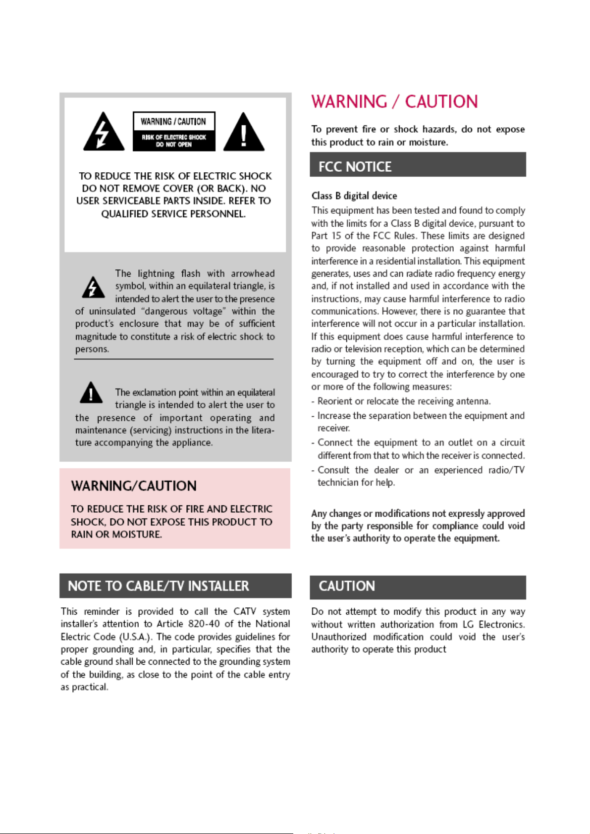
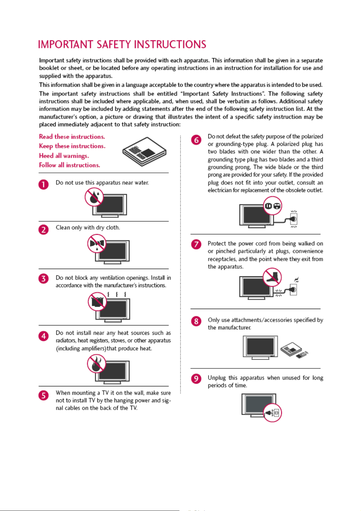
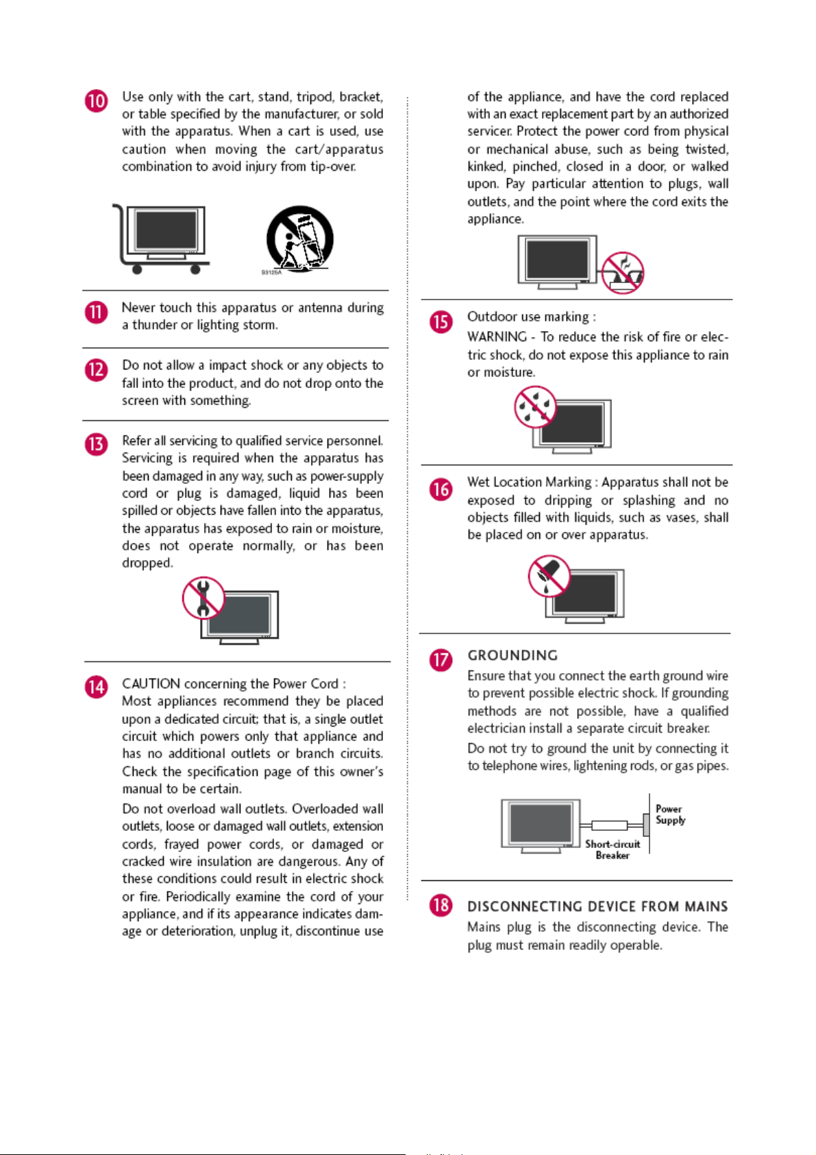
Product Safety
Page 4
Page 5
Page 6

Specification
Penal Spec. for 32” model
Page 7
Page 8
Page 9
Page 10
Page 11

Penal Spec. for 37” model
Page 12

Page 13

Page 14

Page 15

Page 16

Page 17

Z32LC6D
LG P/N :
FAB30009502
LG P/N :
FAB30012602
LG P/N :
FAB30016403
LG P/N :
FAB30012001
LG P/N :
FAB30018405
LG P/N :
FAB30123502
LG P/N :
FAB30013614
Page 18

LG P/N :
FAB30013210
LG P/N :
FAB30007701
LG P/N : FAB30013210
LG P/N : FAB30016415
Z37LC6D
LG P/N :
FAB30013614
LG P/N :
FAB30013210
LG P/N :FAB30012602
Page 19

LG P/N :
FAB30016415
LG P/N :
FAB30012001
LG P/N :
FAB30007507
LG P/N :
FAB30006308
LG P/N :
FAB30123502
LG P/N :
FAB30018405
Page 20

LG P/N :
FAB30009502
LG P/N :
FAB30016403
LG P/N :
FAB30013210
LG P/N :
FAB30007701
Page 21

ADJUSTMENT INSTRUCTION
1. Application Range
These instructions are applied to all of the LCD TV, LA75C
Chassis.
2. Notice
1) Because this is not a hot chassis, it is not necessary to use
an isolation transformer. However, the use of isolation
transformer will help protect test instrument.
2) Adjustment must be done in the correct order. But it is
flexible when its factory local problem occurs.
3) The adjustment must be performed in the circumstance of
25±5°C of temperature and 65±10% of relative humidity if
there is no specific designation.
2.4 The input voltage of the receiver must keep 100~220V,
50/60Hz.
2.5 Before adjustment, execute Heat-Run for 30 minutes.
O After Receive 100% Full white pattern (06CH) then
process Heat-run
(Or 6. White Pattern condition of Ez – Adjust)
O How to make set white pattern
A. Press Power ON button of Service Remocon
B. Press ADJ button of Service remocon to enter “Ez-
Adjust”. Select "6. WHITE PATTERN" and press
A
key. And 100% Full White pattern appear.
In this status you can maintain Heat-Run useless any
pattern generator.
Notice) If you maintain one picture over 20 minutes
(Especially sharp distinction black with white pattern
– 13Ch, or Cross hatch pattern – 09Ch) then it can
appear image stick near black level
3. MICOM Download(Option)
3-1. Required Test Equipment
(1) JIG-LEVER TYPE for adjusting: 1EA
(2) PC & MONITOR: 2EA
(3) BOARD for INTERFACE: IIC & ISP BOARD: 2EA
(4) 15P D-SUB CABLE: 2EA
(5) Using the 12/15 line of D-SUB 15P
12-SDA/15-SCL
3-2. JIG Connection
3-3. Establishment Program
(1) Establish LGE Monitor Tools v1.1
(2) The program work and it is opened program window as
seen below.
(3) Click the first icon shown in fig.9. The window seen in
fig.10 should appear.
connection
to PC
connection
to PC
Page 22

3-4. Set Method
(1) MCU Select: MTV412M128
(2) Option
R/W Option: Auto Write(Verity)
Jig Option: Myson
Transmit Speed: Medium
(3) Check: Just do it with blank micom.
(4) PORT
Chose Parallel Port (normal LPT1)
Attention: You must chose EPP when select Rom BIAS at
LPT
3-5. Download Method
(1) Click the Load File.
(2) Locate and select the correct file from your computer.
(*.hex).
(3) Click the Send.
(4) When you see (ISP COMPLETE) the download is
complete.
4. Using RS-232C
(1) Necessary items before Adjustment items
- Pattern Generator : (MSPG-925FA)
- Adjust 480i Comp1 (MSPG-925FA:model :209 , pattern :65)
- Adjust 1080p Comp1/RGB (MSPG-925FA : model : 225,
pattern :65)
(2) Adjustment sequence
- ad 00 00 : Enter the ADC Adjustment mode.
- kb 00 04 : Change the mode to Component1 (No actions)
- ad 00 10 : Adjust 480i Comp1(Change the mode and
adjustment action)
- kb 00 06 : Change to RGB-DTV mode(No action)
- ad 00 10 : Adjust 1080p Comp1/RGB(Change the mode and
adjustment action)
- ad 00 90 : End of the adjustment
(3) Adjustment protocol
Order Command Set response
1. Inter the Adjustment mode ad 00 00 d 00 OK00x
2. Change the Source kb 00 04 b 00 OK04x (Adjust 480i Comp1)
kb 00 06 b 00 OK06x (Adjust 1080p Comp1/RGB)
3. Start Adjustment ad 00 10
4. Return the Response OKx ( Success condition )
NGx ( Failed condition )
5. Read Adjustment data (main) (main)
ad 00 20 000000000000000000000000007c007b006dx
(sub) (Sub)
ad 00 21 000000070000000000000000007c00830077x
6. Confirm Adjustment ad 00 99 NG 03 00x (Failed condition)
NG 03 01x (Failed condition)
NG 03 02x (Failed condition)
OK 03 03x (Success condition)
7. End of Adjustment ad 00 90 d 00 OK90x
Page 23

5. ADC-Set adjustment
5-1. Synopsis
ADC-set is Gain and Black level setting at Analog to Digital
converter, and compensate the RGB deviation
5-2. Test Equipment
Service R/C, 801GF(802V, 802F, 802R) or MSPG925FA
Pattern Generator (It can output 480i/1080i horizontal 100%
color bar pattern signal, and its output level must setting
0.7V±0.1V p-p correctly)’
5-3. Adjustment
(1) ADC 480i Component1 adjustment
1) Set Component 480i mode and 100% Horizontal Color
Bar Pattern(HozTV31Bar), then set TV set to
Component1 mode and its screen to "NORMAL"
2) After get the signal, wait more a second and enter the
"Ez-Adjust" with press ADJ key of Service remocon.
After then select "2.ADC 480i Comp1" with navigator
button and press "Enter". It is automatically adjustment
3) You can see "ADC Component1 Success" message
after Adjustment success
Error Messages: When its adjustment is not correct,
"ADC Component1 480i Fail" message displayed. If
component is not connection "Component1 Not
Connected", its format is not 480i then "Not Valid
Format", its signal don’t out then "Check Signal Status"
message displayed. These messages will be displayed
just a second.
(2) ADC 1080p Component1 / RGB adjustment
- Check connection both of Component1 and RGB
- MSPG-925FA -> Model: 225, Pattern 65
1) Set Component 1080p mode and 100% Horizontal Color
Bar Pattern(HozTV31Bar), then set TV set to
Component1 mode and its screen to "NORMAL"
2) After get the signal, wait more a second and enter the
"Ez-Adjust" with press ADJ key of Service remocon.
After then select "4.ADC 1080p Comp1/RGB" with
navigator button and press "Enter". First, it is
automatically adjustment Component1.
3) If adjustment is correctly finished, "ADC Component1
Success" message will be displayed. But adjustment is
not correctly finished, "ADC Component1 1080p Fail"
message will be displayed.
4) After adjustment Component1 mode, move to RGB-DTV
mode automatically and RGB adjustment start. After
RGB Adjustment successfully finished, "ADC RGB
1080P Success" message will be displayed.
5) If Adjustment doesn’t success, check conditions all of
the adjustment condition and adjustment again. See
"Error Messages" sentence.
6) After adjustment finished, press "ADJ" key and exit from
Adjustment mode.
6. EDID
(The Extended Display Identification Data)
/
DDC
(Display Data Channel)
Download
6-1. Summary
It is established in VESA, for communication between PC and
Monitor without order from user for building user condition. It
helps to make easily use realize "Plug and Play" function.
6-2. Write HDMI EDID data
(1) Using instruments
1) Jig. (PC Serial to D-Sub connection) for PC, DDC
adjustment.
2) S/W for DDC recording (EDID data write and read)
3) D-sub jack
4) Additional HDMI cable connection Jig.
(2) Preparing and setting.
1) Set instruments and Jig. Like fig.4), then turn on PC and
Jig.
2) Operate DDC write S/W (EDID write & read)
3) It will operate in the DOS mode.
<Fig. 1> Adjustment Mode
<Fig. 2> Adjustment Pattern: 480i/1080P 60Hz HozTV30 Bar Pattern
<Fig. 3> Device configuration diagram for HDMI EDID Data input
LCD TV SET
(or Digital Board)
Page 24

6-3. EDID DATA for LA75C
(1) EDID data for LA75A Chassis
- HDMI1 EDID (DDC (Display Data Channel) Data
* 128byte
* 256byte
- HDMI2 EDID (DDC (Display Data Channel) Data
* 128byte
* 256byte
- Analog (RGB) EDID table - 128byte
* See Working Guide if you want more information about EDID
communication.
7. Adjustment of White Balance
- Purpose: to reduce the difference in color temperature
among modules
- Principal: A module is in full dynamic range when RGB Gain
on OSD is 192. To adjust the white balance without causing
full dynamic range and full data, fix one of RGB Gains at 192
and control the other two by reducing them from 192.
7-1. Required Equipment
(1) Color Analyzer : CA-110 or CA-210
(2) Automatic adjustor (with automatic adjustment necessity
and the RS-232C communication being possible)
7-2. Connection Diagram of Equipment
for Measuring (Automatic Adjustment)
Use the internal pattern to adjust White Balance. The pattern
is automatically given when the automatic adjustment device
is connected or when a user presses ADJ on the remote
controller to start Ez Adjust and then selects 6.White-Balance.
*
When you adjust LCD color temperature, on color analyzer
(CA-210), you should use Channel 9 which is Matrix
compensated (White, Red, Green, Blue revised) by CS-1000
and adjust in accordance with White balance adjustment
coordinate which is specified on the next.
7-3. Adjustment of White Balance
(Automatic Adjustment)
(1) Turn on the POWER ON(
Â) of the remote controller to set
the adjustment and then start the automatic adjustment or
set the Baud Rate to 115200.
(2) Start the adjustment from “wb 00 00” and complete it at
“wb 00 ff”. (Adjust the offset if necessary)
- wb 00 00 the automatic adjustment of White Balance is
started.
- wb 00 10 adjusting gain (internal pattern appears) is
started.
- ja 00 ff adjusting data
- jb 00 c0
- ...
- wb 00 1f adjusting gain is completed.
- Adjust the offset (from wb 00 20 to wb 00 2f) if necessary.
- wb 00 ff the automatic adjustment of White Balance
(internal pattern disappears) is completed.
CA-100+
COLOR
ANALYZER
TYPE; CA-100+
Full W hite Patter n
RS-232C
Connection Diagram of Automatic Adjustment
Page 25

* RS-232C Command (Automatic Adjustment)
- LA75C Chassis Model All
7-4. White Balance Adjustment(Manual)
(1) Test Equipment: CA-210
(2) Manual adjustment sequence is like bellowed one.
1)Turn to "Ez-Adjust" mode with press ADJ button of
service remocon.
2) Select "9.Test Pattern" with CH+/- button and press
enter. Then set will go on Heat-run mode. Over 30
minutes set let on Heat-run mode.
3) Let CA-210 to zero calibration and must has gap more
10cm from center of LCD module when adjustment.
4) Press "ADJ" button of service remocon and select
"6.White-Balance" in "Ez-Adjust" then press "
G" button
of navigation key. (When press "
G" button then set will
go to full white mode)
5) Adjust at three mode (Cool, Medium, Warm)
- When R Gain is fixed at 192
:
Control G Gain and B Gain by reducing them from 192.
- When B Gain is fixed at 192,
:
Control R Gain and G Gain by reducing them from 192.
- When G Gain is fixed to 192,
: Control R Gain and B Gain by reducing them from 192.
Fix one of three Gains (R Gain, G Gain, and B Gain) at 192
and control the other two by reducing values from 192 to
prevent it from increasing.
(When RGB Gains are all 192, the module is in full dynamic
range.)
R Gain
G Gain
B Gain
R Cut
G Cut
B Cut
jg
jh
ji
Cool
ja
jb
jc
Mid
RS-232C COMMAND
[CMD ID DATA]
CENTER
(DEFAULT)(Decimal)
jd
je
jf
00
00
00
192
192
192
Warm
Min
Max
(Deci
mal)
64
64
64
Cool
64
64
64
Mid
64
64
64
Warm
Page 26

UL Vertical Force Stability Warning
Page 27

Guide for Trouble Shooting
Page 28

Page 29

Page 30

Circuit Operation Theory
Page 31

EXPLODED VIEW
300
200
800
802
803
801
121
120
850
840
500
510
511
900
910
901
805
550
530
806
804
807
521
520
830
810
540
820
400
Page 32

EXPLODED VIEW PARTS LIST
No.
Part No.(Quisda)
Part No.(LG)
DESCRIPTION
120 EAB38761001
Speaker,Full Range, EN1257C-6724 ND 10W 8OHM 81DB 120HZ 187mmX30mm LUG KOREA TOPTONE
121 EAB33893101
Speaker,Tweeter, EN10D-6714 ND 10W 8OHM 82DB 0HZ 68 X 23 X 22.7 LUG KOREA TOPTONE
200 EAJ41865401
LCD,Module-TFT, LC470WUN-SAB1 FULLHD 47INCH 1920X1080 500CD COLOR 72% 16/9 1300:1(basic) ZRT
Pol. 5ms(GTG) Dimm.10%(Ext-PWM) 10bit(D) 10000K 22CCFL(Sanken) With Inverter Vitiaz3 LG Display Co. Ltd.
300 6K.0GR02.001 ABJ65882701
Cabinet Assembly, Z47LC6DF LA75A 47” Qisda OS SVC P/N(6K.0GR02.001), ZENITH LOGO, C/A ASSY
400 6K.0GR03.002 ACQ65882901
Cover Assembly,Rear, Z47LC6DF LA75A 47” Qisda OS SVC P/N(6K.0GR03.001), BACK COVER ASSY
500 EBR42821603 PCB Assembly,Sub, SUB T.T LA74A Z42/47LC6DF-UL - SUB T.T OEM IR TOTAL
510 EBR43920301 PCB Assembly,Sub, SUB T.T LA75C Z32/37LC6D KUSTZJK KEY CONTROL TOTAL
511 6K.0GK05.011 ABA56902101
Bracket Assembly, CONTROL Z32LC6D LA75C Qisda OS SVC P/N(6K.0GK05.001), CONTROL BUTTON ASSY
520 EBR43310402 PCB Assembly,Sub, SUB T.T LA75A Z42LC6DF-UL AUSTZHX(CKD) OEM MODEL
521 6K.0GM05.011 ABA57467501
Bracket Assembly, SIDE AV Z42LC6DF LA75A QISDA OS SVC P/N(6K.0GM05.001), SIDE AV BRACKET ASSY
530 EAY32816901 SMPS,AC/DC, FSP327-6F01 90VTO264V 375W 50/60 CB, UL, IEC600,650 etc... LCD
47inch SPI PSU for New chassis(E3 etc...) FSP Technology Inc.
540 EBU42853603 Main Total Assembly, Z47LC6DF-UL BRAND LA75A
550 3D.0GK02.001 MJH49414801
Supporter, PRESS EGI 1.2T Supporter SECC(EGI) Qisda OS SVC P/N(3D.0GK02.001), AC HOLDER
800 3K.0GR01.001 MGJ55136601
Plate,Metal, PRESS SECC 1.6 FRAME SECC QISDA OS SVC P/N(3K.0GR01.001), METAL BAR TOP, Z47LC6DF
801 3K.0GR02.001 MGJ55136701
Plate,Metal, PRESS SECC 1.6 FRAME SECC QISDA OS SVC P/N(3K.0GR02.001), METAL BAR BOTTOM, Z47LC6DF
802 3K.0GR04.001 MGJ55136901
Plate,Metal, PRESS SECC 1.2 FRAME SECC QISDA OS SVC P/N(3K.0GR04.001), METAL BAR LEFT, Z47LC6DF
803 3K.0GR03.001 MGJ55136801
Plate,Metal, PRESS SECC 1.2 FRAME SECC QISDA OS SVC P/N(3K.0GR03.001), METAL BAR RIGHT, Z47LC6DF
804 3K.0GR08.011 MGJ55137701
Plate,Metal, PRESS SECC 1.2 FRAME SECC QISDA OS SVC P/N(3K.0GR08.001), METAL BAR HORIZONTAL TOP, Z47LC6DF
805 3K.0GR09.011 MGJ55137901
Plate,Metal, PRESS SECC 2.0 FRAME SECC QISDA OS SVC P/N(3K.0GR09.001), METAL BAR HORIZONTAL BOTTOM, Z47LC6DF
806 3K.0GR05.011 MGJ55137501
Plate,Metal, PRESS SECC 1.6 FRAME SECC QISDA OS SVC P/N(3K.0GR05.001), METAL BAR LEFT, Z47LC6DF
807 3K.0GR10.001 MGJ55137101
Plate,Metal, PRESS SECC 1.6 FRAME SECC QISDA OS SVC P/N(3K.0GR10.001), METAL BAR RIGHT, Z47LC6DF
810 TY.3D290.004 MGJ39860903
Plate,Shield, PRESS GALVALUME 0.6 SHIELD EGI C/SKD of the item “01” (37”,42”,47”)
820 TY.3D290.003 MGJ39304004
Plate,Shield, PRESS SPTE 0.5 SHIELD SPTE PRESS SPTE 0.5 for 37_42_47CHICAGO CHASSIS
830 TY.3D290.005 MGJ41175002 Plate,Shield, PRESS SPTE 0.5 SHIELD SPTE 47LB9 FOR POWER, NCT
840 4B.0GK01.001 MES49984401
Indicator, MOLD PC PRE AMP Z42LC6DF PC NON QISDA OS SVC(4B.0GK01.001), IR INDICATOR
850 4B.0GK02.001 MES49984301
Indicator, MOLD PMMA POWER Z42LC6DF PMMA NON QISDA OS SVC(4B.0GK02.001), POWER INDICATOR
900 6K.0GR04.001 AAN65883001
Base Assembly, STAND Z47LC6DF LA75A Qisda OS SVC P/N(6K.0GR04.001), STAND ASSY
901 3K.0GR06.001 MJH55138201
Supporter, PRESS SECC 2.0 Supporter SECC(EGI) QISDA OS SVC P/N(3K.0GR06.001), STAND SUPPORTER, Z47LC6DF
910 6K.0GR05.001 MAZ55135101
Bracket, MOLD HIPS STAND Z47LC6DF LA75A HIPS QISDA SVC P/N(6K.0GR05.001), STAND BRACKET
 Loading...