

Page 1
SERVICE MANUAL
Product Type: PLASMA
Chassis: RF-02CA
Manual Series: PV154
Manual Part #: 923-03499
Model Line: E
Product Year: 2002
12/12/02
PRELIMINARY
-
Model Series:
P50W26
P50W26B
-
Made/Printed
in the U.S.A.
CONTENTS
OVERVIEW................................................. 5
USERS MENUS ............................................ 9
SERVICING .............................................. 12
PARTS .................................................... 23
DIAGRAMS ...................................................... 25
SCHEMATICS .................................................... 33
Published September 2002
by Technical Publications
Zenith Electronics Corporation
201 James Record Road
Huntsville, Alabama 35824-1513
Copyright 2002 by Zenith Electronics Corporation
Page 2
PRODUCT SAFETY GUIDELINES
IMPORTANT SAFETY NOTICE
This manual was prepared for use only by properly trained audio-visual service
technicians.
When servicing this product, under no circumstances should the original
design be modified or altered without permission from Zenith Electronics
Corporation. All components should be replaced only with types identical to
those in the original circuit and their physical location, wiring and lead dress
must conform to original layout upon completion of repairs.
Special components are also used to prevent x-radiation, shock and fire hazard.
These components are indicated by the letter “x” included in their component
designators and are required to maintain safe performance. No deviations are
allowed without prior approval by Zenith Electronics Corporation.
Circuit diagrams may occasionally differ from the actual circuit used. This way,
implementation of the latest safety and performance improvement changes into
the set is not delayed until the new service literature is printed.
CAUTION: Do not attempt to modify this product in any way. Never perform
customized installations without manufacturer’s approval. Unauthorized
modifications will not only void the warranty, but may lead to property damage
or user injury.
Service work should be performed only after you are thoroughly familiar with
these safety checks and servicing guidelines.
GRAPHIC SYMBOLS
The exclamation point within an equilateral triangle is intended
to alert the service personnel to important safety information in
the service literature.
The lightning flash with arrowhead symbol within an equilateral
triangle is intended to alert the service personnel to the presence
of noninsulated “dangerous voltage” that may be of sufficient
magnitude to constitute a risk of electric shock.
The pictorial representation of a fuse and its rating within an
equilateral triangle is intended to convey to the service personnel
the following fuse replacement caution notice:
CAUTION: FOR CONTINUED PROTECTION AGAINST RISK OF FIRE,
REPLACE ALL FUSES WITH THE SAME TYPE AND RATING AS MARKED
NEAR EACH FUSE.
TIPS ON PROPER INSTALLATION
1. Never install any receiver in a closed-in recess, cubbyhole, or closely
fitting shelf space over, or close to, a heat duct, or in the path of heated
air flow.
2. Avoid conditions of high humidity such as: outdoor patio installations
where dew is a factor, near steam radiators where steam leakage is a factor,
etc.
3. Avoid placement where draperies may obstruct venting. The customer
should also avoid the use of decorative scarves or other coverings that
might obstruct ventilation.
4. Wall- and shelf-mounted installations using a commercial mounting kit
must follow the factory-approved mounting instructions. A product mounted
to a shelf or platform must retain its original feet (or the equivalent
thickness in spacers) to provide adequate air flow across the bottom. Bolts
or screws used for fasteners must not touch any parts or wiring. Perform
leakage tests on customized installations.
5. Caution customers against mounting a product on a sloping shelf or in a
tilted position, unless the receiver is properly secured.
6. A product on a roll-about cart should be stable in its mounting to the cart.
Caution the customer on the hazards of trying to roll a cart with small
casters across thresholds or deep pile carpets.
7. Caution customers against using a cart or stand that has not been listed
by Underwriters Laboratories, Inc. for use with its specific model of
television receiver or generically approved for use with TVs of the same or
larger screen size.
8. Caution customers against using extension cords. Explain that a forest of
extensions, sprouting from a single outlet, can lead to disastrous
consequences to home and family.
SERVICE INFORMATION
While servicing, use an isolation transformer for protection from AC line shock.
After the original service problem has been corrected, make a check of the
following:
FIRE AND SHOCK HAZARD
1. Be sure that all components are positioned to avoid a possibility of
adjacent component shorts. This is especially important on items transported to and from the repair shop.
2. Verify that all protective devices such as insulators, barriers, covers,
shields, strain reliefs, power supply cords, and other hardware have been
reinstalled per the original design. Be sure that the safety purpose of the
polarized line plug has not been defeated.
3. Soldering must be inspected to discover possible cold solder joints, solder
splashes, or sharp solder points. Be certain to remove all loose foreign
particles.
4. Check for physical evidence of damage or deterioration to parts and components, for frayed leads or damaged insulation (including the AC cord), and
replace if necessary.
5. No lead or component should touch a receiving tube or a resistor rated at
1 watt or more. Lead tension around protruding metal surfaces must be
avoided.
6. After reassembly of the set, always perform an AC leakage test on all exposed
metallic parts of the cabinet (the channel selector knobs, antenna terminals,
handle and screws) to be sure that set is safe to operate without danger of
electrical shock. DO NOT USE A LINE ISOLATION TRANSFORMER DURING THIS
TEST. Use an AC voltmeter having 5000 ohms per volt or more sensitivity in
the following manner: Connect a 1500 ohm, 10 watt resistor, paralleled by
a .15 mfd 150V AC type capacitor between a known good earth ground
water pipe, conduit, etc.) and the exposed metallic parts, one at a time.
Measure the AC voltage across the combination of 1500 ohm resistor and
.15 mfd capacitor. Reverse the AC plug by using a non-polarized adaptor
and repeat AC voltage measurements for each exposed metallic part. Voltage
measured must not exceed 0.75 volts RMS. This corresponds to 0.5 milliamp
AC. Any value exceeding this limit constitutes a potential shock hazard and
must be corrected immediately.
PV154 - 923-03499 2 P50W26 - SAFETY
Page 3

TABLE OF CONTENTS
OVERVIEW ........................................................ 5
GENERAL INFO ........................................... 5
SPECIFICATIONS ..................................... 5
INSTALLATION........................................ 5
CONNECTING A COMPUTER ....................... 5
FRONT ................................................... 6
BACK..................................................... 6
REMOTE CONTROL .................................... 7
SERVICING ................................................ 9
OVERVIEW ............................................. 9
RGB AUTO CUT-OFF & MIN BIAS ................. 9
MAX BIAS ADJUSTMENT ........................... 9
POWER PCB ASSY VOLTAGE ....................... 9
ADJUSTMENT OF WHITE BALANCE ............ 1 0
DDC DATA INPUT ................................... 1 1
COMPONENT OFF-SET ADJUSTMENT .......... 11
EXTERNAL CONTROL .................................. 12
OVERVIEW ........................................... 1 2
CONNECTION ........................................ 12
RS-232C CONFIGURATIONS ..................... 12
SET ID ................................................. 12
COMMUNICATION .................................. 13
NO VIDEO 1 .......................................... 18
NO SOUND ........................................... 1 8
TROUBLESHOOTING................................... 19
NO VIDEO 2 .......................................... 19
NO SOUND ........................................... 1 9
MODEL PARTS ....................................... 2 0
COMPONENT PARTS ............................... 20
DIAGRAMS ............................................... 27
P50W26 EXPLODED VIEW ....................... 2 7
P50W26 INTERCONNECT DIAGRAM .......... 28
P50W26 BLOCK DIAGRAM ...................... 29
P50W26 MAIN PCB ............................... 30
P50W26 OTHER PCBS ............................ 31
P50W26 OTHER PCBS ............................ 32
SCHEMATICS ............................................ 33
CIRCUIT .............................................. 33
CIRCUIT .............................................. 34
CIRCUIT .............................................. 35
CIRCUIT .............................................. 36
CIRCUIT .............................................. 37
CIRCUIT .............................................. 38
CIRCUIT .............................................. 39
CIRCUIT .............................................. 40
CIRCUIT .............................................. 41
PV154 - 923-03499 3 P50W26 - TOC
Page 4

Page 5
Overview
OVERVIEW
GENERAL INFO
SPECIFICATIONS
Screen Size 50 in diagonal
Aspect Ratio 16:9 (width:height)
Max Resolution 1366 x 768p
Peak Brightness 230 cd/m (with Filter);
Module: 510 cd/m2
Contrast Ratio 600:1
Pixel Pitch 0.270 (H) x 0.810 (V)
Viewing Angle 160° horizontally and ver-
tically
Displayable Colors 16.77 million
Color Temperature 8000K Fixed
Display Frequency 15.73 to 68kHz (H); 50 to
80 kHz (V)
Format Conversion Intelligent Image Scaling
to 1280 x 720p
Aspect Ratio Correction 16:9, 4:3 Zoom
Scan Converter Faroudja, Sage
Multi-Lingual Menus English, French, Spanish,
Korean, Portugese
Operating Humidity Range 20–80%
Operating Max Altitude 2000m
Operating Temperature Minus 5 °C – 45 °C
Temperature Range Minus 20 °C – 60 °C
Power Consumption 560 Watts
Power Source 120V 60Hz
*Designs and specifications are subject to change
without notice.
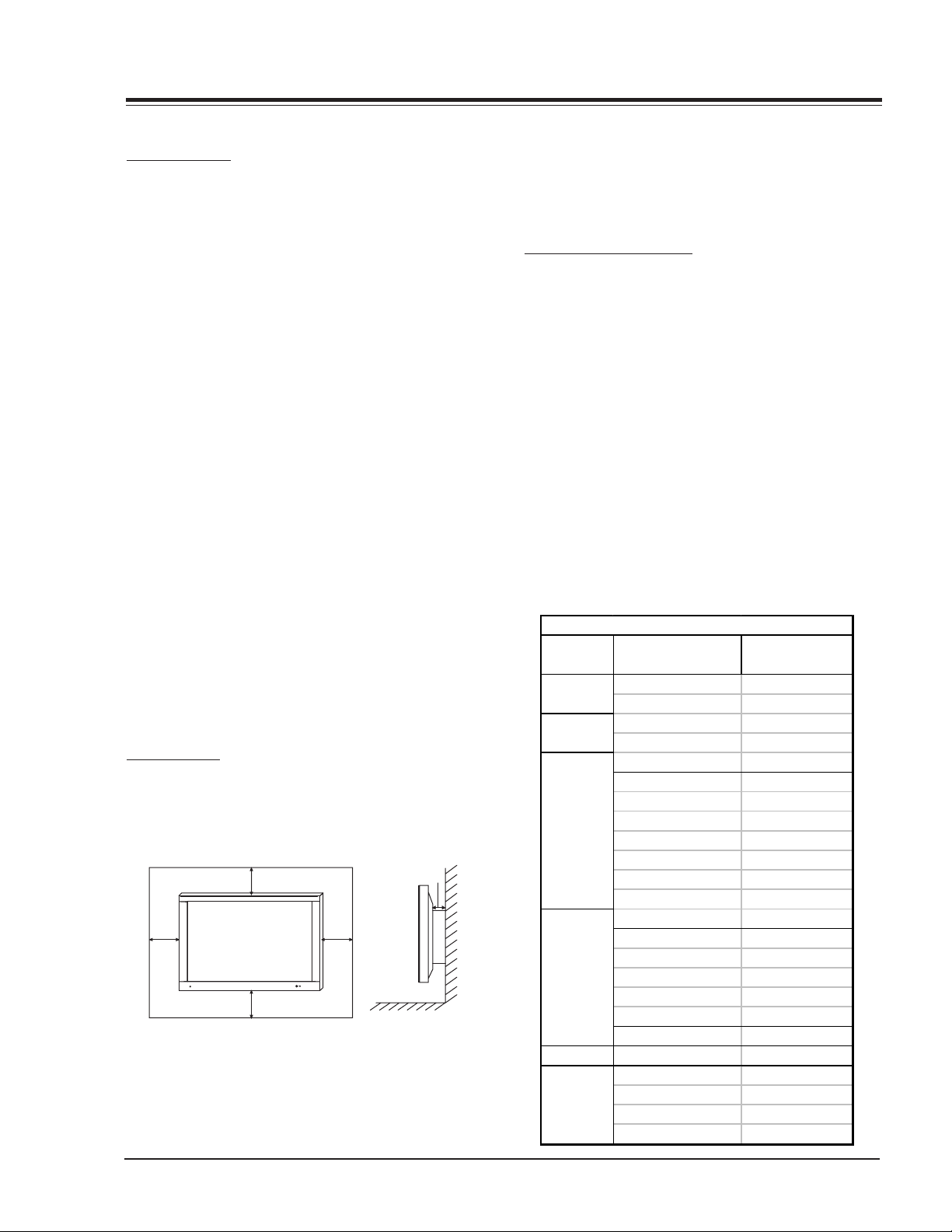
INSTALLATION
It is recommended that this product only be used at an
altitude of less than 6562 feet (2000m) to get the best
quality picture and sound. This plasma display is designed
to be mounted horizontally (wide viewing).
4inch
4inch4inch
4inch
- Your P50W26, P50W26B models (Monitor) can be
installed on a wall or on a desktop pedestal. Wall mount
1.18inch
and stands are optional and not supplied with the
monitor. (For further information, refer to the optional
Tilt/Wall Mounting Bracket Installation and Setup Guide.)
Install this monitor only in a location where adequate
ventilation is available. Minimum allowable clearances for
adequate ventilation are show in the picture.
CONNECTING A COMPUTER
Connect the video output of the PC to the Monitor RGBPC INPUT (VGA/SVGA/XGA) RGB-DTV INPUT (480p/720p/
1080i) using a standard shielded VGA cable. Connect
the audio out from the PC to the Audio jacks on the
Monitor (Audio cables are not included with the Monitor).
Set the computer video output to SXGA (1280x1024) or
lower resolution. If the video output of the PC is not
compatible with the Monitor, no picture will appear on
the Monitor (see chart). Use the video/pc button on the
remote control to select the RGB source. To set up this
monitor in a PC Windows environment select Standard
monitor. This monitor does not support Plug and Play
function.
Note: Avoid prolonged display of a still image, as it may
cause a permanent image to remain even after you
change the image.
P42W22 Computer Video
Resolution
640x350
640x400
640x480
800x600
832x624 49.725 74.55
1024x768
Horizontal Frequency
(KHz)
31.468 70.09
37.861 85.08
31.469 70.08
37.927 85.03
31.469 59.94
35.000 66.66
37.861 72.80
37.500 75.00
43.269 85.00
45.913 90.03
53.011 100.04
64.062 120.00
35.156 56.25
37.879 60.31
48.077 72.18
46.875 75.00
53.674 85.06
56.000 90.00
64.016 100.00
48.363 60.00
56.476 70.06
60.023 75.02
68.677 84.99
Vertical Frequency
(KHz)
PV154 - 923-03499 5 P50W26 - OVERVIEW
Page 6
OVERVIEW
FRONT
Power Standby Indicator
Illuminates red in standby
mode, green when the
Monitor is on.
Remote Control Sensor
Input Select
INPUT
MENU
VOL
SELECT
ON/OFF
Menu
Channel
Volume
Main Power Button
BACK
YPBP
COMPONENT
(DVD/DTV INPUT)
R
AUDIO
R
AUDIO
INPUT
(MONO)
AUDIO
L
()()
R
(8‰)EXTERNAL SPEAKER
AC INPUT
R
AUDIO
INPUT
VIDEO
INPUT
S-VIDEO
1 2 3 4785 6 1
1. EXTERNAL SPEAKER (8 ohm output)
Connect to the optional external speaker(s).
2. POWER CORD SOCKET
This monitor operates on an AC power. The voltage is
indicated on the Specifications page. Never attempt to
operate the monitor on DC power.
3. AUDIO/VIDEO INPUT JACKS
Connect audio/video out from external equipment to these
jacks.
ON/ OFF
L
RGB1 INPUT
CONTROL
LOCK
REMOTE
CONTROL
RGB1 OUTPUT
(PC/DTV OUTPUT)
AUDIO
INPUT
(PC/DTV INPUT)
RGB2 INPUT
(DIGITALRGB INPUT)
4. COMPONENT INPUT JACKS
480i/480p/720p/1080i
5. CONTROL LOCK Locks the front keyboard. The remote
must be used to control the TV.
6. RGB OUTPUT
Loop out to another monitor.
7. RGB INPUT
RGB signal input. Accepts VGA or DVI inputs.
8. RS-232C INPUT
Service port.
RS-232C INPUT
(CONTROL/SERVICE)
()()
L
EXTERNAL SPEAKER
(8 )
PV154 - 923-03499 6 P50W26 - OVERVIEW
Page 7
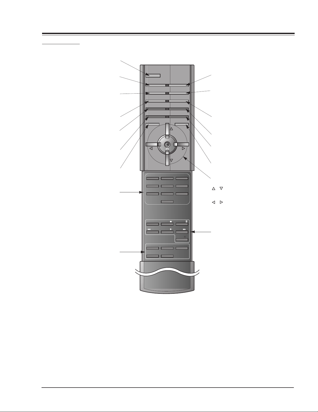
REMOTE CONTROL
OVERVIEW
Switches the Monitor on from
POWER
standby or off to standby.
SLEEP
Sets the sleep timer.
APC
Adjusts the factory preset picture
accordingtotheroom.
ARC
Changes the picture format.
PIP
Switchesthesubpictureonoroff.
SWAP
Exchanges main and sub picture
images.
MENU
Displays on screen menus one by one.
Exits the current menu.
Memorizes menu changes.
NUMBER buttons
POWER
SLEEP INPUT SELECT
APC DASP
ARC PIP ARC
PIP
SWAP
MENU MUTE
VOL
123
456
7809
TWIN PICTURE
SUB INPUT
OK
VOL
INPUT SELECT
Selects:
VIDEO, S-VIDEO, RGB1/2 or
COMPONENT mode.
DASP
To select the sound appropriate to
your viewing program character:
FLAT, SPORTS, CINEMA, MUSIC,or
USER
PIP ARC
Changes the PIP picture format.
TWIN PICTURE
SUB INPUT
Selects the input mode for the sub
picture.
MUTE
Switchesthesoundonoroff.
OK
/
Selects a menu option.
/ (Volume button)
Increases/decreases sound level.
Adjusts menu settings.
Adjusts the sub picture size.
WIN. SIZE
WIN.POSITION
Moves the sub picture.
SPLIT ZOOM
Enlarge the screen with regular
ration.
ZOOM-/ZOOM+
Enlarges or reduces
the main picture size.
POWER STOP
REW
PLAY FF
WIN.SIZE
WIN.POSITION
ZOOM -
ZOOM +
P/STILL
REC
SPLIT ZOOM
VCR BUTTONS
Controls some video cassette
recorder.
PV154 - 923-03499 7 P50W26 - OVERVIEW
Page 8

Page 9

SERVICING
SERVICING
OVERVIEW
Because this is not a hot chassis, it is not necessary to
use an isolation transformer. However, the use of isolation
transformer will help protect test instrument.
Adjustments must be done in the correct order. The
adjustment must be performed at 25±5
and 65±10% of relative humidity.
The input voltage of the receiver must maintain
110~240V, 50/60Hz while adjusting. Operate the receiver
for about 15 minutes prior to the adjustment with 100%
white pattern (06CH), or white condition in HEAT-RUN
mode.
Enter into HEAT-RUN mode. Press the POWER ON KEY on
R/C for adjustment. OSD display HEAT-RUN WHITE and
screen display 100% full WHITE PATTERN. Set is activated
HEAT-RUN without signal generator in this mode. Single
color pattern of HEAT-RUN mode uses to check the PANEL
(RED/BLUE/GREEN).
Caution: If you turn on a still screen more than 20 minutes,
an afterinage may occur in the black level part of
the screen. (Especially Digital Cross Hatch Pattern),
a afterimage may be occur in the black level part
of the screen.
RGB AUTO CUT-OFF & MIN BIAS
1) If the PDP Module or Power Board was replaced, adjust the Power PCB Assy Voltage prior to any other
adjustment.
2) Input Full Back (0 Gray) signal which generated from
Pattern Generator into Component input and RGB1
Input part.
3) Press POWER ON KEY on R/C for adjustment and select
AUTO-CUT(Cut-off Auto Adjustment).
4) Press Vol. + key.
5) Screen adjustment starts with Full Black screen. Original Window screen will be presented about 5-6 seconds later. And if (OK OSD) appears on the screen,
then the Auto Cut-off and Min-Bias adjustment will
have been completed.
o
C of temperature
(5) After adjustment, press ¥ key to save adjustment
and come out of the adjustment mode.
To check whether the circuit adjustment is operated well
or not:
1) Display RGB1 to the Main picture, Component
input to the Sub picture in the TWIN PICTURE.
2) To check the MIN-Bias, input Full Black (0 gray) signal into Component input and RGB1 input part at the
same time in the Pattern Generator.
3) To check the MAX-Bias, input Full White (255 gray)
signal into Component input and RGB1 input part
at the same time in the Pattern Generator.
4) Compare Black Level with White Level by eye. And
if there is no Level difference, the adjustment is
completed.
Data value, which adjusted in the board, is valid until
the VSC Board is dissued and must be protected. For the
protection of data, Micom does not permit any more
adjustment after completion.
In case of re-adjustment, operate First Value Setting.
Each PCB Assy must be checked by Check JIG Set before
assembly. (Especially, be careful Power PCB Assy which
can cause fatal Damage to PDP Module.)
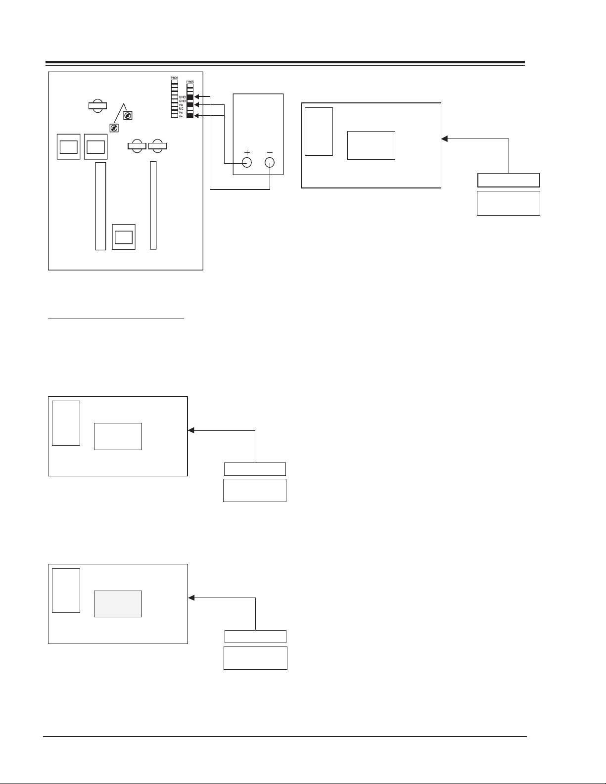
POWER PCB ASSY VOLTAGE
VA ADJUSTMENT
1) Test Equipment : D.M.M 1EA
2) After receiving 100% white pattern, HEAT RUN.
3) Connect + terminal of D.M.M to Va pin of P805
and connect Ð terminal to GND pin of P805.
4) After turning the VR4, voltage of D.M.M adjust-
ment as same as Va voltage which on label of panel
Right/Top. (Deviation : ±0.5V)
VS ADJUSTMENT
1) Connect + terminal of the D.M.M to Vs pin of
P805 and connect - terminal to GND pin of P805.
2) After turning the VR1, voltage of D.M.M ad-
justment as same as Vs voltage which on label
of panel Right/Top. (Deviation : ±0.5V)
MAX BIAS ADJUSTMENT
1) Input Full White (255 Gray) signal which generated
from Pattern Generator into Component input and
RGB1 Input.
2) Press POWER ON KEY on R/C for adjustment and select
MAX-BIAS.
3) Press Vol. + key.
4) Original Full White screen will be presented about
1-2 seconds later. And if (OK OSD) appears on the
screen then the Min-Bias adjustment will have been
completed.
PV154 - 923-03499 9 P50W26 - SERVICING
Page 10
SERVICING
Va voltage
adjustment
variable resistor
VR4
VR1
<Fig 1> Connection Diagram of Power Adjustment
ADJUSTMENT OF WHITE BALANCE
REQUIRED EQUIPMENT
Color analyzer (CA-100 or same product)
CONNECTION DIAGRAMS (MANUAL ADJUSTMENT)
COLOR
ANALYZER
R-L 70
G-L 70
R-M 128
G-M 128
R-H 216
G-H 216
High Light
216 Gray Level
135 140Cd/
§‡
CA-100
RGB Signal Input
PDP MONITOR
MSPG-2100 or
<Fig 2> Connection Diagram of Manual
Adjustment(High Light)
COLOR
ANALYZER
R-L 70
G-L 70
R-M 128
G-M 128
R-H 216
G-H 216
Middle Light
128 Gray Level
70~75Cd/
§‡
CA-100
RGB Signal Input
PDP MONITOR
MSPG-2100 or
Fig 3> Connection Diagram of Manual
Adjustment(Middle Light)
DMM
Window
MSTG-5200
Window
MSTG-5200
COLOR
ANALYZER
R-L 70
G-L 70
R-M 128
G-M 128
R-H 216
G-H 216
Low Light
70 Gray Level
20~25Cd/§‡
CA-100
RGB Signal Input
PDP MONITOR
Window
MSPG-2100 or
MSTG-5200
<Fig 4> Connection Diagram of Manual
Adjustment(Low Light)
ADJUSTMENT OF WHITE BALANCE
Operate the Zero-calibration of the CA-100, then stick
sensor to PDP module surface when you adjust. For
manual adjustment, it is also possible by the following
sequence.
1) Select WHITE PATTERN of HEAT RUN mode by pressing POWER ON KEY on remote control for adjustment then operate HEAT RUN more than 15 minute.
2) Supply 216Gray, 128Gray, 70Gray Level, 50% size
length and breadth signal to RGB1 input. (Refer
to Fig 2,3,4)
3) W/B adjustment must be adjusted once and follow
the sequence of Low Light —> Middle Light —>
High Light and then save the adjustment value
with o Key.
4) To adjust Low Light, stick sensor to Gray Level(or
20~25 Cd/m2) Pattern, press ADJ Key on R/C for
adjustment and press v, x on R/C in adjustment
mode to select R-L or G-L, press VOL +, - Key and
adjust it until color coordination becomes as below.
X: 0.290±0.003, Y: 0.300±0.003
Color temperature: 8, 500oK±500oK
5) To adjust Middle Light , stick sensor to Gray Level
(or 70~75 Cd/m2) Pattern, press ADJ Key on R/
C for adjustment and press v, x on R/C in adjustment mode to select R-M or G-M, press VOL +, Key and adjust it until color coordination becomes
as below.
X: 0.290±0.003, Y: 0.300±0.003
Color temperature: 8, 500oK±500oK
6) To adjust High Light, stick sensor to Gray Level(or
135-140 Cd/m2) Pattern, press ADJ Key on the
R/C for adjustment and press v, x on R/C in adjustment mode to select R-L or G-L, press VOL +,
- Key and adjust it until color coordination becomes as below.
PV154 - 923-03499 10 P50W26 - SERVICING
Page 11

SERVICING
X: 0.290±0.003, Y: 0.300±0.003
Color temperature: 8, 500¡K±500¡K
7) Exit adjustment mode using o Key.
DDC DATA INPUT
REQUIRED TEST EQUIPMENT
1) A jig for adjusting PC, DDC. (PC serial to Dsub. Connection equipment)
2) S/W for writing DDC(EDID data write & read)
3) D-Sub 15P cable, D-Sub to DVI Connector (Connect to DVI Jack)
PREPARATION FOR ADJUSTMENT
1) Set devices as above and turn the PC, jig on.
2) Put S/W for writing DDC (EDID data write &
read) into operation. (operated in DOS mode.)
SEQUENCE OF ADJUSTMENT
DDC DATA INPUT FOR ANALOG-RGB
1) Put the set on the table and turn the power on.
2) Connect PC Serial to D-sub 15P Cable of JIG for
DDC adjustment to RGB1 terminal (D-Sub 15Pin).
3) Operate S/W for DDC record and select DDC Data for
analog RGB in Model Menu.
4) Operate EDID Write command.
5) Operate EDID Read command and check whether
Check Sum is OK.
6) If Check Sum is NG, repeat 3-4.
7) If Check Sum is OK, DDC Data for Analog-RGB input
is completed.
COMPONENT OFF-SET ADJUSTMENT
1) Input the signal to HD-STB(SK-010T) and receive 14Ch.
2) Input Video signal and Component 720P, 1080i signal of HD-STB into AV1 and Component input part.
3) Select Twin Picture by pressing ADJ twice on R/C, check
component in the main picture and AV1 in the sub
picture.
4) Adjust the R-OFFSET, B-OFFSET color impression of
component(Main picture) and external Input(Sub
picture) same by pressing Volume +,- key.
DDC DATA INPUT FOR DIGITAL-RGB
1) Connect PC Serial to DVI Cable of JIG for DDC
adjustment to RGB2 terminal (DVI Jack).
2) Operate S/W for DDC record and select DDC Data for
Digital RGB in Model Menu.
3) Operate EDID Write command.
4) Operate EDID Read command and check whether
Check Sum is OK.
5) If Check Sum is NG, repeat 3 & 4.
6) If Check Sum is OK, DDC Data for Digital-RGB input
is completed.
PV154 - 923-03499 11 P50W26 - SERVICING
Page 12
SERVICING
EXTERNAL CONTROL
OVERVIEW
Connect the RS-232C input jack to an external control
device (such as a computer or an A/V control system)
and control the set’s functions externally.
Connect the serial port of the control device to the RS232C jack on the Monitor back panel. RS-232C
connection cables are not supplied with the set. The
set’s remote control and front panel controls (except main
power) will not be functional if the set is controlled by a
PC computer or other external device.
CONNECTION
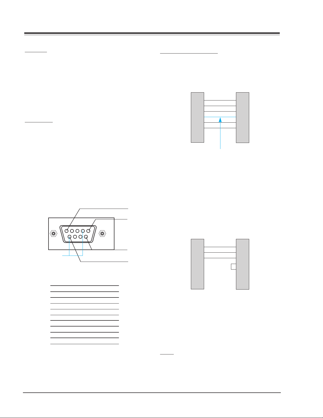
Type of connector is a D-Sub 9-pin male (Use a null
modem/serial cable). Wire the 7-Wire cable so that each
pair of data lines cross between the two devices. These
data line pairs are RXD (Receive data) and TXD (Transmit
data), DTR (DTE side ready) and DSR (DCE side ready),
and RTS (Ready to send) and CTS (Clear to send).
When using the 3-Wire cable connected to RXD, TXD and
GND; Pin No. 4 (DTR) and Pin No. 6 (DSR) must be
connected to the monitor. (The cable must be
disconnected from the Monitor to be able to use the
remote control and Monitor front panel controls.)
1
control device.
RS-232C CONFIGURATIONS
7-WIRE CABLE CONFIGURATION
7-wire configuration
(Standard RS-232C cable)
PDP
3
2
5
6
4
8
7
DB 9
TXD
RXD
GND
DSR
DTR
CTS
RTS
RXD
TXD
GND
DTR
DSR
RTS
CTS
PC
2
3
5
4
6
7
8
DB 9
Control line
The Monitor is available to switch between external
adjustment and remote control adjustment using a
control line. If the control line is high, the monitor is
controlled by the external control device. If the control
line is low, the Monitor is controlled by the Monitor’s
remote control.
3-WIRE CABLE CONFIGURATION
5
Pin No.4 and Pin
No.6 must be
connected on
monitor side.
No. Pin name
1 No connection
2 RXD (Receive data)
3 TXD (Transmit data)
4 DTR (DTE side ready)
5 GND
6 DSR (DCE side ready)
7 RTS (Ready to send)
8 CTS (Clear to send)
9 No Connection
9
6
With the RS-232 input connected, the set cannot be
controlled by both an external control device and the
remote control at the same time. The set can only be
controlled by either the remote control or the external
3-wire configuration
(Not standard)
PDP
3
2
5
4
6
7
8
DB 9
TXD
RXD
GND
DTR
DSR
RTS
CTS
RXD
TXD
GND
DTR
DSR
RTS
CTS
PC
2
3
5
4
6
7
8
DB 9
When using a 3-Wire cable configuration there is no
control line. The external control device must put the
Monitor into the “change into remote control
adjustment mode”. The Monitor will then be able to
be controlled by the remote control. If the Monitor is
turned back on, it will revert back to external device
control.
SET ID
Set ID to specify a monitor identification number. Press
the menu button and then use the up/down button to
select the SPECIAL menu. Press the vol (G) button.
Use the up/down buttons to select SET ID and then press
PV154 - 923-03499 12 P50W26 - SERVICING
Page 13

the volume up button. Use the volume button to adjust
Transmission
*
[Command] : To control PDP set.
*
[Set ID] : You can adjust the set ID to choose
desired monitor ID number in special
menu. See page 47. Adjustment range
is 1 ~ 99.
When selecting Set ID 0, every connected
PDP set is controlled.
*
[DATA] : To transmit command data.
Transmit FF data to read status of
command.
*
[Cr] : Carriage Return
ASCII code 0x0D
*
[ ] : ASCII code space (0x20)
[Command][ ][Set ID][ ][Data][Cr]
OK Acknowledgement
* The Monitor transmits ACK (acknowledgement) based
on this format when receiving normal data. At this
time, if the data is data read mode, it indicates present
status data. If the data is data write mode, it returns
the data of the PC computer.
[Set ID][:][OK][x][Data][x]
Error Acknowledgement
* The Monitor transmits ACK (acknowledgement) based
on this format when receiving abnormal data from
non-viable functions or communication errors.
[Set ID][:][NG][x]
Transmission / Receiving Protocol
SET ID to choose a desired monitor ID number. The
adjustment range for SET ID is 1- 99. Default monitor ID
is 1.
COMMUNICATION
COMMUNICATION PARAMETERS
• Baud rate: 2400 bps (UART)
• Data length: 8 bits
• Parity: None
• Stop bit: 1 bit
• Communication code: ASCII code
If the command interval is interrupted for more than
4 seconds, only Command 1 will be recognized. Be
careful when using the power command.
COMMAND REFERENCE LIST
NAME COMMAND DATA RANGE
01. Power p 0 - 1
02. Input Select i 0 - 3
03. Aspect Ratio r 0 - 2
04. Screen mute m 0 - 1
05. Volume mute w 0 - 1
06. Volume control v 0 - 64
07. Contrast k 0 - 64
08. Brightness b 0 - 64
09. Color c 0 - 64
10. Tint t 0 - 64
11. Sharpness s 0 - 64
12. OSD select d 0 - 1
13. Abnormal state a 0 - 1
14. PIP z 0 - 3
15. PIP input select e 0 - 1
16. PIP sound select u 0 - 1
17. PIP position x 0 - 3
18. remote control
adjustment mode
Note: Data values are written in hexidecimal. They must be
passed to the monitor in Hexidecimal form.
SERVICING
j0 - 1
PV154 - 923-03499 13 P50W26 - SERVICING
Page 14

SERVICING
01. Power (Command:p)
To control Power On/Off of the Monitor.
Transmission
[p][ ][Set ID][ ][Data][Cr]
Data 0 : Power Off
1 : Power On
* Example : Power on for set ID No.3.
Type : P 3 1 0x0D
Acknowledgement
[Set ID][:][OK][x][Data][x]
Data 0 : Power Off
1 : Power On
* In example : Monitor Acknowledges power on for set ID
No.3.
To show Power On/Off.
Transmission
[p][ ][Set ID][ ][FF][Cr]
Acknowledgement
[Set ID][:][OK][x][Data][x]
Data 0 : Power Off
1 : Power On (RGB)
2 : Power On (Video)
3 : Power On (Component)
4 : Power On (S-Video)
* In like manner, if other functions transmit FF data
based on this format, Acknowledgement data feed
back presents status about each function.
02. Input select (Command:i)
03. Aspect Ratio (Command:r)
To adjust the screen format.
You can also adjust the screen format using the ratio
(Aspect Ratio Control) button on remote control or in
the Special menu.
Transmission
[r][ ][Set ID][ ][Data][Cr]
Data 0 : Wide screen (16:9)
1 : Normal screen (4:3)
2 : Full screen (Zoom)
Acknowledgement
[Set ID][:][OK][x][Data][x]
Data 0 : Wide screen (16:9)
1 : Normal screen (4:3)
2 : Full screen (Zoom)
* Using the PC input, you select either 16:9 or 4:3 screen
aspect ratio.
* Using the DTV 720p/1080i input, you can only select
16:9 screen aspect ratio.
04. Screen mute (Command:m)
To select screen mute on/off.
Transmission
[m][ ][Set ID][ ][Data][Cr]
Data 0 : Screen mute on (Picture off)
1 : Screen mute off (Picture on)
Acknowledgement
[Set ID][:][OK][x][Data][x]
Data 0 : Screen mute on (Picture off)
1 : Screen mute off (Picture on)
To select input source for the Monitor.
You can also select an input source using the
video/pc button on the Monitor’s remote control.
Transmission
[i][ ][Set ID][ ][Data][Cr]
Data 0 : RGB
1 : AV (Video)
2 : Component
3 : S-AV (S-Video)
Acknowledgement
[Set ID][:][OK][x][Data][x]
Data 0 : RGB
1 : AV (Video)
2 : Component
3 : S-AV (S-Video)
PV154 - 923-03499 14 P50W26 - SERVICING
05. Volume mute (Command:w)
To control volume mute on/off.
You can also adjust mute using the mute button on
remote control.
Transmission
[w][ ][Set ID][ ][Data][Cr]
Data 0 : Volume mute on (Volume off)
1 : Volume mute off (Volume on)
Acknowledgement
[Set ID][:][OK][x][Data][x]
Data 0 : Volume mute on (Volume off)
1 : Volume mute off (Volume on)
Page 15

SERVICING
06. Volume control (Command:v)
To adjust volume.
You can also adjust volume with the volume buttons
on remote control.
Transmission
[v][ ][Set ID][ ][Data][Cr]
Data Min : 0 ~ Max : 64
Acknowledgement
[Set ID][:][OK][x][Data][x]
Data Min : 0 ~ Max : 64
Refer to Real data mapping as shown below.
*
07. Contrast (Command:k)
To adjust screen contrast.
You can also adjust contrast in the Picture menu.
Transmission
[k][ ][Set ID][ ][Data][Cr]
Data Min : 0 ~ Max : 64
Acknowledgement
[Set ID][:][OK][x][Data][x]
Data Min : 0 ~ Max : 64
Refer to Real data mapping as shown below.
*
08. Brightness (Command:b)
To adjust screen brightness.
You can also adjust brightness in the Picture menu.
Transmission
[b][ ][Set ID][ ][Data][Cr]
09. Color (Command:c)
To adjust the screen color.
You can also adjust color in the Picture menu.
Transmission
[c][ ][Set ID][ ][Data][Cr]
Data Min : 0 ~ Max : 64
Acknowledgement
[Set ID][:][OK][x][Data][x]
Data Min : 0 ~ Max : 64
Refer to Real data mapping as shown below.
*
10. Tint (Command:t)
To adjust the screen tint.
You can also adjust tint in the Picture menu
Transmission
[t][ ][Set ID][ ][Data][Cr]
Data Red : 0 ~ Green : 64
Acknowledgement
[Set ID][:][OK][x][Data][x]
Data Red : 0 ~ Green : 64
Refer to Real data mapping as shown below.
*
11. Sharpness (Command:s)
To adjust the screen sharpness.
You can also adjust sharpness in the Picture menu
Transmission
[s][ ][Set ID][ ][Data][Cr]
Data Min : 0 ~ Max : 64
Acknowledgement
[Set ID][:][OK][x][Data][x]
Data Min : 0 ~ Max : 64
Refer to Real data mapping as shown below.
*
Data Min : 0 ~ Max : 64
Acknowledgement
[Set ID][:][OK][x][Data][x]
Data Min : 0 ~ Max : 64
PV154 - 923-03499 15 P50W26 - SERVICING
Refer to Real data mapping as shown below.
*
Page 16

SERVICING
12. OSD select (Command:d)
To select OSD (On Screen Display) on/off.
Transmission
[d][ ][Set ID][ ][Data][Cr]
Data 0 : OSD off
1 : OSD on
Acknowledgement
[Set ID][:][OK][x][Data][x]
Data 0 : OSD off
1 : OSD on
* The remote control and Monitor front panel controls
(except main power) are not operable when the M onitor
is set up to be controlled by the PC computer.
13. Abnormal state (Command:a)
To recognize an a bnormal state.
Transmission
[a][ ][Set ID][ ][FF][Cr]
Acknowledgement
[Set ID][:][OK][x][Data][x]
Data 0 : OK
1 : Fan alarm
2 : 5V down
3 : AC down
This function is read only.
*
14. PIP (Command:z)
To control PIP (Picture-in-Picture). You can also control
PIP using the pip button on re mote control or in the
Special menu.
Transmission
[z][ ][Set ID][ ][Data][Cr]
Data 0 : PIP off
1 : PIP (small)
2 : PIP (large)
Acknowledgement
[Set ID][:][OK][x][Data][x]
Data 0 : PIP off
1 : PIP (small)
2 : PIP (large)
PIP only works in the following re solutions:
*
RGB PC 640x480 (VGA) / 800x600(SVGA) / 1024x768
(XGA) (only in vertical frequency 60Hz),
Component 480p / 720p / 1080i.
15. PIP input select (Command:e)
To select input source for sub picture in P IP mode.
You can also se lect source using input select button
on the remote control or in the Special menu.
Transmission
[e][ ][Set ID][ ][Data][Cr]
Data 0 : AV (VIDEO)
1 : COMPONENT
2 : S-AV (S-VIDEO)
Acknowledgement
[Set ID][:][OK][x][Data][x]
Data 0 : AV (VIDEO)
1 : COMPONENT
2 : S-AV (S-VIDEO)
COMPONENT source only works with 480i input signal.
*
PV154 - 923-03499 16 P50W26 - SERVICING
Page 17

SERVICING
16. PIP sound select (Command:u)
To select main or sub (inse t) sound for PIP.
You can also se lect sound select in PI P on the
special me nu.
Transmission
[u][ ][Set ID][ ][Data][Cr]
Data 0 : Main picture sound
1 : Sub picture sound
Acknowledgement
[Set ID][:][OK][x][Data][x]
Data 0 : Main picture sound
1 : Sub picture sound
COMPONENT source only works in 480i input signal.
*
17. PIP position (Command:x)
To select sub picture position for PI P.
You can also a djust the sub picture position using the
position button on the remote control or in PIP on the
Special menu.
18. Change into Remote control
adjustment mode (Command:j)
To control the M onitor with the remote control while
the cable is still connected.
Transmission
[j][ ][Set ID][ ][Data][Cr]
Data 1 : Remote control adjustment mode
Acknowledgement
[Set ID][:][OK][x][Data][x]
Data 0 : PC adjustment mode
1 : Remote control adjustment mode
* If external equipment commands the Monitor to
"change into remote control adjustment mode", the
Monitor can only be adjusted by the remote control.
To revert the Monitor control to external control de vice
adjustment, turn the Monitor off and then on again.
Transmission
[x][ ][Set ID][ ][Data][Cr]
Data 0 : Right down on scree n
1 : Left down on screen
2 : Left up on screen
3 : Right up on screen
Acknowledgement
[Set ID][:][OK][x][Data][x]
Data 0 : Right down on screen
1 : Left down on screen
2 : Left up on screen
3 : Right up on screen
PV154 - 923-03499 17 P50W26 - SERVICING
Page 18

NO VIDEO 1
SERVICING
No video
Check Input of AC
(90~225V)
Normal
Check ST-BY LED ON
Main S/W ON
Normal
Check LED YELLOW
Sub S/W ON
Normal
Check conditions of and
various connectors
Abnormal
Abnormal
Abnormal
Connect plug with the set
Check AC Line Fuse
Check voltage of Vs after
disconnecting with CN802,
CN803, CN804. Check short
of Q603, Q703.
If found in good condition
go to Video 2.
Abnormal
Replace Q603, Q703
NO SOUND
Check a connective
condition of sound power
cable
Check voltage of sound
terminal
Check connection with
F8811 Fuse
Check connection
line of speaker
PV154 - 923-03499 18 P50W26 - SERVICING
Page 19

TROUBLESHOOTING
NO VIDEO 2
Abnormal Picture
SERVICING
Input PC signal
Normal
Check CXA2101
IC203
Normal
Check ADV7123
IC406
Normal
Check FLI2220
IC404
Normal
Check FLI2200
IC403
Normal
Abnormal
Check
IC501
Check 74F541D
IC902~IC905
Check cable of pin 41
P902
Check VPC3230
IC201
Normal
Check Input jack & Connector
NO SOUND
Check connector
speaker to set
PV154 - 923-03499 19 P50W26 - SERVICING
Check MSP3401
IC601
Check LA4282
IC603
Check Input
Jack
Page 20

All 50” models are module level repair only. Parts contact
information is below.
Voice: 1-888-3-ZENITH
Fax: 1-888-6-ZENITH
Mail: Zenith National Parts
201 James Record Road
Huntsville, AL 35824-1513
PARTS
P50W26
Loc. Part No Description
200 6348Q-C030C PDP 50" 16:9 1365*768 DU
201 6871QCH019A PCB ASSY,DI CTRL
202 6871QDH030A PCB ASSY,DI YDRV
203 6871QDH031A PCB ASSY,DI YDRV
204 6871QLH018A PCB ASSY,DI XRLT
205 6871QLH019A PCB ASSY,DI XRLT
206 6871QPH006A PCB ASSY,MA DCDC ASSY
207 6871QRH016A PCB ASSY,DI XRRT ASSY
208 6871QRH017A PCB ASSY,DI XRRT ASSY
209 6871QXH011A PCB ASSY,DI XRCT ASSY
210 6871QXH012A PCB ASSY,DI XRCT ASSY
211 6871QYH020A PCB ASSY,DI YSUS ASSY
212 6871QZH021A PCB ASSY,DI ZSUS ASSY
213 4980V00416A SUP ASSY RIG
214 4980V00416B SUP ASSY LEF
215 4980V00498A SUP ASSY, SMPS
300 3091V00433F CABINET STEREO RF
301 4980V00361A SUPPORTER FILTER TOP
302 4980V00362A SUPPORTER FILTER BOTTOM
303 4980V00363A SUPPORTER FILTER SIDE
305 3790V00311C WINDOW GLASS FILTER
310 5020V00688B BUTTON CONTROL
320 320-062H SPRING COIL
330 5020V00645B POWER BUTTON
400 3809V00292A BACK COVER ASSY INNER
401 3301V00009D PLATE ASSY AV
410 3809V00293C BACK COVER ASSY
520 6871VMMC08A PCB MAIN RF-02CA
530 6871VSMD10A PCB EXTRA RF-02CA 50IN
540 6871VSMD04A PCB INTER RF-02CA I/F NT
550 6871VSMD06A PCB A/V RF-02CA 50IN AUD
560 6871VSMD11A PCB SPK RF-02CA 50IN RIG
561 4980V00384A SUP INTERFACE MN-50
570 3141VSNA57A CHASSIS SUB RF-02CA
580 6871VSMD08A PCB KBD RF-02CA 50IN
581 5020V00647A BUTTON CONTROL INNER
590 6871VSMD09A PCB PSW RF-02CA 50IN
591 5020V00648A POWER BUTTON INNER MN-50PZ4
600 6871VSMN17A PCB EXTRA RF02CA
610 3501V00085A BOARD ASSY P-BOARD
P50W26B
Loc. Part No. Description
200 6348Q-C030C PDP 50" 16:9 1365*768 DU
201 6871QCH019A PCB ASSY,DI CTRL
202 6871QDH030A PCB ASSY,DI YDRV
203 6871QDH031A PCB ASSY,DI YDRV
204 6871QLH018A PCB ASSY,DI XRLT
205 6871QLH019A PCB ASSY,DI XRLT
206 6871QPH006A PCB ASSY,MA DCDC ASSY
207 6871QRH016A PCB ASSY,DI XRRT ASSY
208 6871QRH017A PCB ASSY,DI XRRT ASSY
209 6871QXH011A PCB ASSY,DI XRCT ASSY
210 6871QXH012A PCB ASSY,DI XRCT ASSY
211 6871QYH020A PCB ASSY,DI YSUS ASSY
212 6871QZH021A PCB ASSY,DI ZSUS ASSY
213 4980V00416A SUP ASSY RIG
214 4980V00416B SUP ASSY LEF
215 4980V00498A SUP ASSY, SMPS
300 3091V00433E CABINET STEREO RF
301 4980V00361A SUPPORTER FILTER TOP
302 4980V00362A SUPPORTER FILTER BOTTOM
303 4980V00363A SUPPORTER FILTER SIDE
305 3790V00311C WINDOW GLASS FILTER
310 5020V00688A BUTTON CONTROL
320 320-062H SPRING COIL
330 5020V00645A POWER BUTTON
400 3809V00292A BACK COVER ASSY INNER
401 3301V00009D PLATE ASSY AV
410 3809V00293B BACK COVER ASSY
520 6871VMMC08A PCB MAIN RF-02CA
530 6871VSMD10A PCB EXTRA RF-02CA 50IN
540 6871VSMD04A PCB INTER RF-02CA I/F NT
550 6871VSMD06A PCB A/V RF-02CA 50IN AUD
560 6871VSMD11A PCB SPK RF-02CA 50IN RIG
561 4980V00384A SUP INTERFACE MN-50
570 3141VSNA57A CHASSIS SUB RF-02CA
580 6871VSMD08A PCB KBD RF-02CA 50IN
581 5020V00647A BUTTON CONTROL INNER
590 6871VSMD09A PCB PSW RF-02CA 50IN
591 5020V00648A POWER BUTTON INNER MN-50PZ4
600 6871VSMN17A PCB EXTRA RF02CA
610 3501V00085A BOARD ASSY P-BOARD
PV154 - 923-03499 20 P50W26 - MODEL PARTS
Page 21

Page 22

Page 23

Diagrams
301
303
200
204
213
302
300
305
214
215
610
520
560
530
401
570 400
410
310
320
330
581
580
550
540
590
591
212
209
207
202
201
205
210
208
203
211
206
Loc. Part No. Description
200 6348Q-C030C PDP 50" 16:9 1365*768 DU
201 6871QCH019A PCB ASSY,DI CTRL
202 6871QDH030A PCB ASSY,DI YDRV
203 6871QDH031A PCB ASSY,DI YDRV
204 6871QLH018A PCB ASSY,DI XRLT
205 6871QLH019A PCB ASSY,DI XRLT
20 6 6871QPH006A PCB A SSY ,MA DCDC A SS Y
207 6871QRH016A PCB ASSY,DI XRRT ASSY
208 6871QRH017A PCB ASSY,DI XRRT ASSY
209 6871QXH011A PCB ASSY ,DI XRCT ASSY
210 6871QXH012A PCB ASSY ,DI XRCT ASSY
211 6871QYH020A PCB ASSY,DI YSUS ASSY
212 6871QZH021A PCB ASSY,DI ZSUS ASSY
213 4980V00416A SUP ASSY RIG
214 4980V00416B SUP ASSY LEF
215 4980V00498A SUP ASSY, SMPS
300 3091V00433F CABINET STEREO RF
301 4980V00361A SUPPORTER FILTER TOP
302 4980V00362A SUPPORTER FILTER BOTTOM
303 4980V00363A SUPPORTER FILTER SIDE
305 3790V00311C WINDOW GLASS FILTER
310 5020V00688B BUTTON CONTROL
320 320- 062H SPRING COIL
330 5020V00645B POWER BUTTON
400 3809V00292A BACK COVER ASSY INNER
401 3301V00009D PLATE ASSY AV
410 3809V00293C BACK COVER ASSY
520 6871VMMC08A PCB MA IN RF-02CA
530 6871VSMD10A PCB EXTRA RF-02CA 50IN
540 6871VSMD04A PCB INTER RF-02CA I/F NT
550 6871VSMD06A PCB A/V RF-02CA 50IN AUD
560 6871VSMD11A PCB SPK RF-02CA 50IN RIG
561 4980V00384A SUP INTERFACE MN-50
570 3141VSNA57A CHASSIS SUB RF-02CA
580 6871VSMD08A PCB KBD RF-02CA 50IN
581 5020V00647A BUTTON CONTROL INNER
590 6871VSMD09A PCB PSW RF-02CA 50IN
591 5020V00648A POWER BUTTON INNER MN-50PZ4
600 6871VSMN17A PCB EXTRA RF02CA
610 3501V00085A BOARD ASSY P-BOARD
P50W26
Loc. Part No. Description
200 6348Q-C030C PDP 50" 16:9 1365*768 DU
201 6871QCH019A PCB ASSY,DI CTRL
202 6871QDH030A PCB ASSY,DI YDRV
203 6871QDH031A PCB ASSY,DI YDRV
204 6871QLH018A PCB ASSY,DI XRLT
205 6871QLH019A PCB ASSY,DI XRLT
20 6 6871 QPH00 6A PCB A SSY , MA DCDC ASSY
207 6871QRH016A PCB ASSY,DI XRRT ASSY
208 6871QRH017A PCB ASSY,DI XRRT ASSY
209 6871QXH011A PCB ASSY,DI XRCT ASSY
210 6871QXH012A PCB ASSY,DI XRCT ASSY
211 6871QYH020A PCB ASSY,DI YSUS ASSY
212 6871QZH021A PCB ASSY,DI ZSUS ASSY
213 4980V00416A SUP A SSY RIG
214 4980V00416B SUP ASSY LEF
215 4980V00498A SUP A SSY, SMPS
300 3091V00433E CABINET STEREO RF
301 4980V00361A SUPPORTER FILTER TOP
302 4980V00362A SUPPORTER FILTER BOTTOM
303 4980V00363A SUPPORTER FILTER SIDE
305 3790V00311C WINDOW GLA SS FILTER
31 0 5020 V 00 688A BUTTON CONTROL
320 320-062H SPRING COIL
330 5020V00645A POWER BUTTON
40 0 3809 V 00 292A BA CK COVER ASSY INNER
401 3301V00009D PLA TE ASSY AV
410 3809V00293B BACK COVER A SSY
520 6871VMMC08A PCB MAIN RF-02CA
530 6871VSMD10A PCB EXTRA RF-02CA 50IN
540 6871VSMD04A PCB INTER RF-02CA I/F NT
550 6871VSMD06A PCB A/V RF-02CA 50IN AUD
560 6871VSMD11A PCB SPK RF-02CA 50IN RIG
561 4980V00384A SUP INTERFACE MN-50
570 3141VSNA57A CHASSIS SUB RF-02CA
580 6871VSMD08A PCB KBD RF-02CA 50IN
58 1 5020 V 00 647A BUTTON CONTROL INNER
590 6871VSMD09A PCB PSW RF-02CA 50IN
591 5020V00648A POWER BUTTON INNER MN-50PZ4
600 6871VSMN17A PCB EXTRA RF02CA
610 3501V00085A BOARD ASSY P-BOA RD
P50W26B
P50W26 Exploded View
PV154 - 923-03499
27
P50W26 - DIAGRAMS
Page 24

P101
VA
N/C
GND
+15V
GND
+5V
P210
P2
P202
P201
P211
To Plasma
To Plasma
P212
To Plasma
P213
To Plasma
P10
P3
P7
P6
P8
P5
P4
P9
P1
P11
To Plasma
To Plasma
To Plasma
To Plasma
Z - DRIVE
Z - CON BOTTOM
Z - CON TOP
P004B
Control Buttons
P2
P4
P6
P1
P11
P13
To Plasma
+5V
GND
-15V
GND
GND
GND
NC
Vs
Vs
Y - DRIVE LOWER
Y - DRIVE UPPER
CONTROL PCB ASSY
Y - SUS DRIVE AMP
P101
P300
P801
P802
P1720
MICRO/X-Y GENERATOR
PCB ASSY,MAIN
FAN GND
FAN GVCC
GND
GND
12V
12V
GND
GND
GND
5V
5V
5V
GND
5VA
5VA
5VA
5VA
GND
GND
GND
24V
N/C
GND
GND
24V
N/C
5V-MNT
VAVS-ON
GND
STBY
RL-ON
AC-DET
P5
NC
NC
NC
NC
GND
NC
VE
P2
CN810
CN809
CN808
CN3
CN804
CN801
CN803
CN806
P3
VSetup
NC
GND
GND
-Vy
P902
P100
P601A
P1
P806B
P007B
P112P111
To Plasma
To Plasma
P110
To Plasma
5V
5V
5V
GND
GND
GND
12V
12V
GND
GND
NC
NC
+5V
GND
+15V
GND
NC
VA
NC
NC
NC
NC
GND
NC
Vse
5V cnt
GND
15V
GND
GND
NC
175V
175V
-75V
GND
GND
NC
260V
65V
NC
GND
15V
GND
5V cnt
30V
30V
GND
GND
5V cnt
5V cnt
5V cnt
5V cnt
GND
GND
GND
GND
175V
175V
NC
GND
GND
GND
15V
GND
5V
To Plasma
To Plasma
To Plasma
To Plasma
To Plasma
To Plasma
To Plasma
VOL +
GND
GND
GND
5V
TX
GND
POWER
G LED
R LED
VOL -
SEL
REMOTE
GND
5V ST
GND
LED RED
LED GRN
SW1
SW2
SW3
SW4
AC/ON
RL ON
STBY
5V
GND
VS ON
5VMONI
NC
5V
GND
15V
GND
GND
NC
Vs
Vs
P102
CN802
P102
A/C IN
P3
65V
NC
GND
15V
GND
5V cnt
CN811
N-SCL
N-SDA
S-SCL
S-SDA
FS
GND
NOT USED
AC/DC CONVERTOR
EMI FILTER
PCB ASSY POWER
X-DRIVE RIGHT
AV PACK
6871VSMA90B
X-DRIVE LOWER
SPEAKER JACK
P1
P2
P3
P4
P5
P6
P7
P8
P1
P6
P5
P4
P102
CN805
CN807
5Vcnt
GND
15V
GND
NC
65V
5Vcnt
GND
15V
GND
NC
65V
NOTE: Some plug locations on the PWB vary depending on model.
P50W26 Interconnect Diagram
28
P50W26 - DIAGRAMSPV154 - 923-03499
Page 25

P50W26 Block Diagram
PV154 - 923-03499
29
P50W26 - DIAGRAMS
Page 26

MA I N( T OP )
P50W26 Main PCB
30
P50W26 - DIAGRAMSPV154 - 923-03499
Page 27

PRE-AMP(TOP)
PRE-AMP(BOTTOM)
LOCA L K EY(TOP)
LOCA L K EY(BOTTOM)
POWER S/W(TOP)
POWER S/W(BOTTOM)
RIGHT SPK(TOP)
RIGHT SPK(BOTTOM)
AUDIO(TOP)
AUDIO(BOTTOM)
P50W26 Other PCBs
PV154 - 923-03499
31
P50W26 - DIAGRAMS
Page 28

P50W26 Other PCBs
32
P50W26 - DIAGRAMSPV154 - 923-03499
Page 29

Circuit
12345678910
G
F
E
D
C
B
A
CRITICAL SAFETY COMPONENTS ARE IDENTIFIED BY THE LETTER “X“ IN THEIR
COMPONENT DESIGNATORS. REPLACE ONLY WITH PART NUMBERS SPECIFIED.
33 P50W26 SHEET 33PV154 - 923-03499
ALL SYMBOLS WITH “M” ON END OF DESIGNATOR
INDICATE SURFACE MOUNTED COMPONENT
Page 30

Circuit
12345678910
G
F
E
D
C
B
A
CRITICAL SAFETY COMPONENTS ARE IDENTIFIED BY THE LETTER “X“ IN THEIR
COMPONENT DESIGNATORS. REPLACE ONLY WITH PART NUMBERS SPECIFIED.
34PV154 - 923-03499
ALL SYMBOLS WITH “M” ON END OF DESIGNATOR
INDICATE SURFACE MOUNTED COMPONENT
P50W26 SHEET 34
Page 31

Circuit
12345678910
G
F
E
D
C
B
A
CRITICAL SAFETY COMPONENTS ARE IDENTIFIED BY THE LETTER “X“ IN THEIR
COMPONENT DESIGNATORS. REPLACE ONLY WITH PART NUMBERS SPECIFIED.
35 P50W26 SHEET 35PV154 - 923-03499
ALL SYMBOLS WITH “M” ON END OF DESIGNATOR
INDICATE SURFACE MOUNTED COMPONENT
Page 32

Circuit
12345678910
G
F
E
D
C
B
A
CRITICAL SAFETY COMPONENTS ARE IDENTIFIED BY THE LETTER “X“ IN THEIR
COMPONENT DESIGNATORS. REPLACE ONLY WITH PART NUMBERS SPECIFIED.
36PV154 - 923-03499
ALL SYMBOLS WITH “M” ON END OF DESIGNATOR
INDICATE SURFACE MOUNTED COMPONENT
P50W26 SHEET 36
Page 33

Circuit
12345678910
G
F
E
D
C
B
A
CRITICAL SAFETY COMPONENTS ARE IDENTIFIED BY THE LETTER “X“ IN THEIR
COMPONENT DESIGNATORS. REPLACE ONLY WITH PART NUMBERS SPECIFIED.
37 P50W26 SHEET 37PV154 - 923-03499
ALL SYMBOLS WITH “M” ON END OF DESIGNATOR
INDICATE SURFACE MOUNTED COMPONENT
Page 34

Circuit
12345678910
G
F
E
D
C
B
A
CRITICAL SAFETY COMPONENTS ARE IDENTIFIED BY THE LETTER “X“ IN THEIR
COMPONENT DESIGNATORS. REPLACE ONLY WITH PART NUMBERS SPECIFIED.
38PV154 - 923-03499
ALL SYMBOLS WITH “M” ON END OF DESIGNATOR
INDICATE SURFACE MOUNTED COMPONENT
P50W26 SHEET 38
Page 35

Circuit
12345678910
G
F
E
D
C
B
A
CRITICAL SAFETY COMPONENTS ARE IDENTIFIED BY THE LETTER “X“ IN THEIR
COMPONENT DESIGNATORS. REPLACE ONLY WITH PART NUMBERS SPECIFIED.
39 P50W26 SHEET 39PV154 - 923-03499
ALL SYMBOLS WITH “M” ON END OF DESIGNATOR
INDICATE SURFACE MOUNTED COMPONENT
Page 36

Circuit
12345678910
G
F
E
D
C
B
A
CRITICAL SAFETY COMPONENTS ARE IDENTIFIED BY THE LETTER “X“ IN THEIR
COMPONENT DESIGNATORS. REPLACE ONLY WITH PART NUMBERS SPECIFIED.
40PV154 - 923-03499
ALL SYMBOLS WITH “M” ON END OF DESIGNATOR
INDICATE SURFACE MOUNTED COMPONENT
P50W26 SHEET 40
Page 37

Circuit
12345678910
G
F
E
D
C
B
A
CRITICAL SAFETY COMPONENTS ARE IDENTIFIED BY THE LETTER “X“ IN THEIR
COMPONENT DESIGNATORS. REPLACE ONLY WITH PART NUMBERS SPECIFIED.
41 P50W26 SHEET 41PV154 - 923-03499
ALL SYMBOLS WITH “M” ON END OF DESIGNATOR
INDICATE SURFACE MOUNTED COMPONENT
Page 38

12345678910
G
F
E
D
C
B
A
CRITICAL SAFETY COMPONENTS ARE IDENTIFIED BY THE LETTER “X“ IN THEIR
COMPONENT DESIGNATORS. REPLACE ONLY WITH PART NUMBERS SPECIFIED.
42PV154 - 923-03499
ALL SYMBOLS WITH “M” ON END OF DESIGNATOR
INDICATE SURFACE MOUNTED COMPONENT
P50W26 SHEET 42
 Loading...