

Page 1

SERVICE MANUAL
Product Type: PLASMA
Chassis: RF-03GA
Manual Series:
Manual Part #:
Model Line:
Product Year: 2003
P42W34
Model Series:
CONTENTS
Description of Controls .................................................4
Adjustment Instructions...............................................16
Diagrams ...................................................................19
Parts List ...................................................................23
Schematics ....................................................................
Printed Circuit Boards ....................................................
Published June 2003
by Technical Publications
Zenith Electronics Corporation
201 James Record Road
Huntsville, Alabama 35824-1513
Copyright © 2003 by Zenith Electronics Corporation
Printed in Korea
Page 2
- 2 -
IMPORTANT SAFETY NOTICE
This manual was prepared for use only by properly trained audio-visual service
technicians.
When servicing this product, under no circumstances should the original design
be modified or altered without permission from Zenith Electronics Corporation.
All components should be replaced only with types identical to those in the
original circuit and their physical location, wiring and lead dress must conform
to original layout upon completion of repairs.
CAUTION: Do not attempt to modify this product in any way.
Never perform customized installations without manufacturer’s
approval.
Unauthorized modifications will not only void the warranty, but may
lead to property damage or user injury.
Service work should be performed only after you are thoroughly familiar with
these safety checks and servicing guidelines.
GRAPHIC SYMBOLS
The exclamation point within an equilateral triangle is intended to
alert the service personnel to important safety information in the
service literature.
The lightning flash with arrowhead symbol within an equilateral
triangle is intended to alert the service personnel to the presence
of noninsulated “dangerous voltage” that may be of sufficient
magnitude to constitute a risk of electric shock.
The pictorial representation of a fuse and its rating within an
equilateral triangle is intended to convey to the service personnel
the following fuse replacement caution notice:
CAUTION: FOR CONTINUED PROTECTION AGAINST RISK
OF FIRE, REPLACE ALL FUSES WITH THE SAME TYPE AND
RATING AS MARKED NEAR EACH FUSE.
SERVICE INFORMATION
While servicing, use an isolation transformer for protection from AC line shock.
After the original service problem has been corrected, make a check of the
following:
FIRE AND SHOCK HAZARD
1. Be sure that all components are positioned to avoid a possibility of adjacent
component shorts. This is especially important on items transported to and
from the repair shop.
2. Verify that all protective devices such as insulators, barriers, covers, shields,
strain reliefs, power supply cords, and other hardware have been reinstalled
per the original design. Be sure that the safety purpose of the polarized line
plug has not been defeated.
3. Soldering must be inspected to discover possible cold solder joints, solder
splashes, or sharp solder points. Be certain to remove all loose foreign particles.
4. Check for physical evidence of damage or deterioration to parts and
components, for frayed leads or damaged insulation (including the AC cord),
and replace if necessary.
5. No lead or component should touch a receiving tube or a resistor rated at 1
watt or more. Lead tension around protruding metal surfaces must be avoided.
6. After reassembly of the set, always perform an AC leakage test on all
exposed metallic parts of the cabinet (the channel selector knobs, antenna
terminals, handle and screws) to be sure that set is safe to operate without
danger of electrical shock. DO NOT USE A LINE ISOLATION
TRANSFORMER DURING THIS TEST. Use an AC voltmeter having 5000
ohms per volt or more sensitivity in the following manner: Connect a 1500
ohm, 10 watt resistor, paralleled by a .15 mfd 150V AC type capacitor
between a known good earth ground water pipe, conduit, etc.) and the
exposed metallic parts, one at a time.
Measure the AC voltage across the combination of 1500 ohm resistor and
.15 mfd capacitor. Reverse the AC plug by using a non-polarized adaptor
and repeat AC voltage measurements for each exposed metallic part.
Voltage measured must not exceed 0.75 volts RMS. This corresponds to 0.5
milliamp AC. Any value exceeding this limit constitutes a potential shock
hazard and must be corrected immediately.
TIPS ON PROPER INSTALLATION
1. Never install any receiver in a closed-in recess, cubbyhole, or closely fitting
shelf space over, or close to, a heat duct, or in the path of heated air flow.
2. Avoid conditions of high humidity such as: outdoor patio installations where
dew is a factor, near steam radiators where steam leakage is a factor, etc.
3. Avoid placement where draperies may obstruct venting. The customer
should also avoid the use of decorative scarves or other coverings that might
obstruct ventilation.
4. Wall- and shelf-mounted installations using a commercial mounting kit must
follow the factory-approved mounting instructions. A product mounted to a
shelf or platform must retain its original feet (or the equivalent thickness in
spacers) to provide adequate air flow across the bottom. Bolts or screws
used for fasteners must not touch any parts or wiring. Perform leakage tests
on customized installations.
5. Caution customers against mounting a product on a sloping shelf or in a tilted
position, unless the receiver is properly secured.
6. A product on a roll-about cart should be stable in its mounting to the cart.
Caution the customer on the hazards of trying to roll a cart with small casters
across thresholds or deep pile carpets.
7. Caution customers against using a cart or stand that has not been listed by
Underwriters Laboratories, Inc. for use with its specific model of television
receiver or generically approved for use with TVs of the same or larger screen
size.
8. Caution customers against using extension cords. Explain that a forest of
extensions, sprouting from a single outlet, can lead to disastrous
consequences to home and family.
AV
PRODUCT SAFETY GUIDELINES
Page 3

- 3 -
DESCRIPTION OF CONTROLS...........................................4
SPECIFICATIONS.................................................................7
EXTERNAL CONTROL DEVICE SETUP..............................9
IR CODE(NEC FORMAT) ...................................................15
ADJUSTMENT INSTRUCTIONS ........................................17
BLOCK DIAGRAMS............................................................20
ASSEMBLY METHOD.........................................................22
EXPLODED VIEW...............................................................24
EXPLODED VIEW PARTS LIST.........................................25
REPLACEMENT PARTS LIST............................................26
SCHEMATIC DIAGRAM..........................................................
PRINTED CIRCUIT BOARD ...................................................
TABLE OF CONTENTS
Page 4
- 4 -
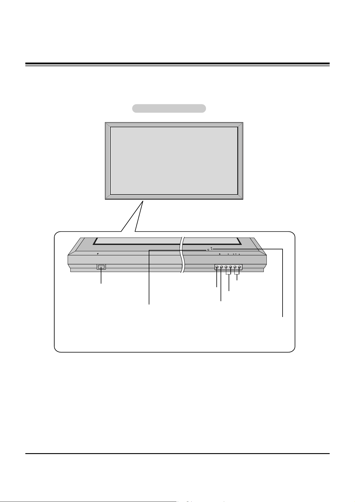
Controls
Controls
VOL.MENU
INPUT
SELECT
ON/OFF
Main Power Button
INPUT SELECT Button
VOLUME (FF,GG) Buttons
Power Standby Indicator
Illuminates red in standby mode,
Illuminates green when the
Plasma display is turned on
Remote Control Sensor
MENU Button
EE, DD
Buttons
Front Panel Controls
Front Panel Controls
DESCRIPTION OF CONTROLS
Page 5
- 5 -
Connection Options
Connection Options
(MONO)
R
AUDIO
VIDEO
L
AV(EXPANDED) INPUT
R
AUDIO
VIDEO
L
AV OUTPUT
EXPANDED OUTPUT
REMOTE
CONTROL
ANT INDC IN
(DC 12V)
+75 Ω
R
( )( )
( )
( )
L
EXPANDED
INPUT
VIDEO
INPUT
RS-232C INPUT
(CONTROL/SERVICE)
EXTERNAL SPEAKER
Y PBP
R
(MONO)
R
AUDIO
L
R
AUDIO
L
S-VIDEO
AC INPUT
AUDIO INPUT
AUDIO INPUT
AUDIO INPUT
REMOTE
CONTROL
COMPONENT INPUT
DVI INPUT
RGB INPUT
RGB OUTPUT
6
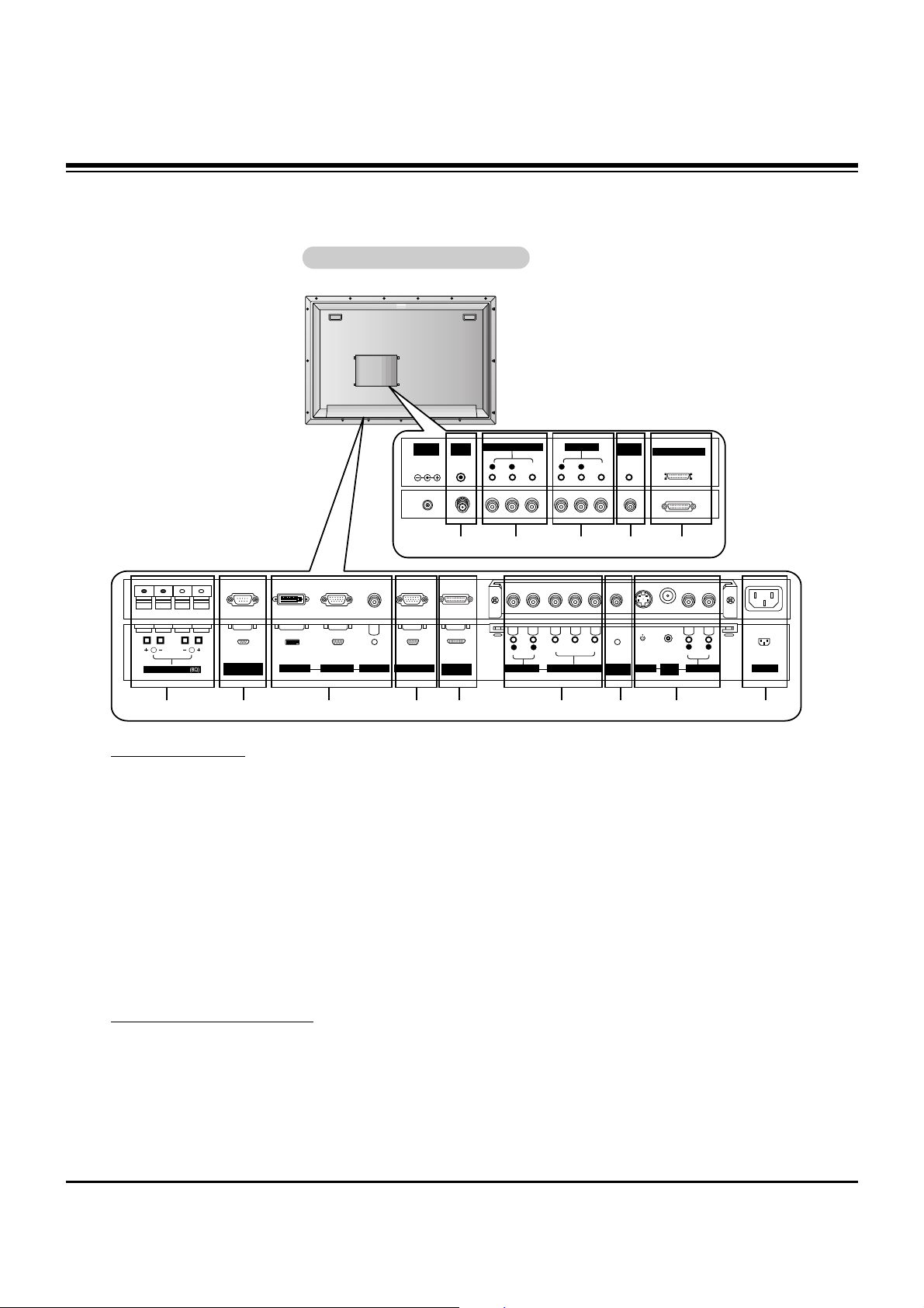
Tuner Connections
1. ANTENNA INPUT PORT
Connection for an over-the-air or terrestrial antenna, your
cable TV wire, or cable box.
2. AV (EXPANDED) INPUT
Connection for audio/video out from external equipment.
3. AV OUTPUT
Connection for a second TV or monitor.
4. REMOTE CONTROL
Connect your wired remote control to the remote control port
on the PDP Tuner.
5. EXPANDED OUTPUT
Connect the Plasma display to the PDP Tuner with the tuner
box cable.
Plasma Display Connections
6. EXTERNAL SPEAKER (8 ohm output)
Connect to optional external speaker(s).
* For further information, refer to ‘Speaker & Speaker
Stand’ manual.
7. RS-232C INPUT (CONTROL/SERVICE) PORT
Connect to the RS-232C port on a PC.
8. DVI (Digital Visual Interface) INPUT/
RGB INPUT/AUDIO INPUT JACKS
Connect the Plasma display output connector from a PC to
the appropriate input port.
9. RGB OUTPUT PORT
You can watch the RGB signal on another monitor, connect
RGB OUTPUT to another monitor’s PC input port.
10. EXPANDED INPUT
Connect the Plasma display to the PDP Tuner with the
tuner box cable supplied.
11. COMPONENT INPUT/AUDIO INPUT JACKS
Connect a component video device to these jacks.
12. REMOTE CONTROL
Connect your wired remote control to the remote control
port on the Plasma display.
13. S-VIDEO INPUTS
Connect S-Video out from an S-VIDEO VCR to the SVIDEO input.
AUDIO/VIDEO INPUT JACKS
Connect audio/video out from external equipment to these
jacks.
14. POWER CORD SOCKET
This Plasma display operates on an AC power. The voltage
is indicated on the Specifications page. Never attempt to
operate the Plasma display on DC power.
Back Connection Panel
Back Connection Panel
7 9 10 128 13 1411
1 2 3 4 5
DESCRIPTION OF CONTROLS
Page 6
- 6 -
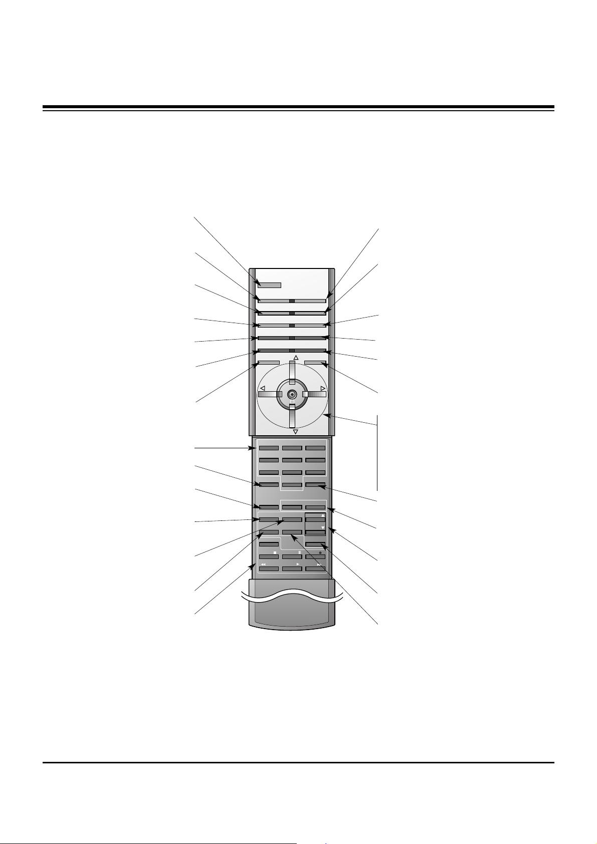
Remote Control Key Functions
Remote Control Key Functions
- When using the remote control, aim it at the remote control sensor on the Plasma display.
- Under certain conditions such as if the remote IR signal is interrupted, the remote control may not function. Press the key again
as necessary.
1 2 3
4 5 6
7 8
0
9
POWER
MULTIMEDIA INPUT SELECT
APC DASP
ARC SLEEP
PIP
DW
SWAP
MENU MUTE
ENTER
VOL
POWER
STOP
FF
REC
PLAY
REW
P/STILL
WIN.SIZE
WIN.POSITION
FAV CH
CAPTION
A.PROG PIP CH
PIP CH
ZOOM +
MTS
ZOOM -
SPLIT ZOOM
MEMORY/ERASE
VOL
CH
CH
PIP INPUT
POWER
Switches the Plasma display
between ON and STANDBY.
MULTIMEDIA
Selects source:
Component, RGB, or DVI
mode.
APC
Adjusts the factory preset picture
according to the room.
ARC
Changes the picture format.
PIP
Switches the sub picture on and off.
SWAP
Exchanges main and sub picture
images.
MENU
Displays on screen menus.
Exits the current menu.
Memorizes menu changes.
ENTER
CH
DD / EE
(Channel button)
Selects the desired channel.
Selects menu options.
VOL
FF / GG
(Volume button)
Increases/decreases sound level.
Adjusts menu settings.
INPUT SELECT
Selects source:
TV, Video (Exp.),
Video, S-Video, Component, RGB, or
DVI mode.
DASP
Selects the sound appropriate to
your viewing program character:
Flat, Music, Movie, Sports, or User.
SLEEP
Sets the sleep timer.
PIP INPUT
Selects the input source mode for
the sub picture.
MUTE
Switches the sound on or off.
ZOOM-/ZOOM+
Enlarges or reduces the main picture
size.
DW (Double Window)
Selects Double Window mode.
PIP CH
DD / EE
Selects the channel for the sub
picture.
MTS
Selects the MTS sound: Mono, Stereo,
or SAP.
FAV CH
Selects favorite channels.
WIN. SIZE
Adjusts the sub picture size.
WIN.POSITION
Moves the sub picture on the screen.
NUMBER buttons
AUTO PROGRAM
Searches for available channels, see
page 18.
MEMORY/ERASE
Memorizes or erases selected
channel.
CAPTION
Selects CAPTION mode.
VCR BUTTONS
Control some LG video cassette
recorders.
SPLIT ZOOM
Enlarges the picture.
DESCRIPTION OF CONTROLS
Page 7

- 7 -
MODEL
Width (inches / mm)
Height (inches / mm)
Depth (inches / mm)
Weight (pounds / kg)
Power requirement
Television System
Program Coverage
Resolution
Color
Operating Temperature Range
Operating Humidity Range
Maximum Elevation
P42W34
Plasma Display Tuner
40.7 / 1033 11 / 208
24.5 / 622 7 / 179.5
3.2 / 81 1.2 / 30.7
75 / 34 2.2 / 1
AC120V, 60Hz
NTSC
VHF 2 ~ 13, UHF 14 ~ 69, CATV 1 ~ 125
852 x 480 (Dot)
16,770,000 (256 steps of each R, G and B)
32 ~ 104°F (0 ~ 40°C)
Less than 80%
6561 feet (2000m)
• The specifications shown above may be changed without notice for quality improvement.
SPECIFICATIONS
Page 8
- 8 -
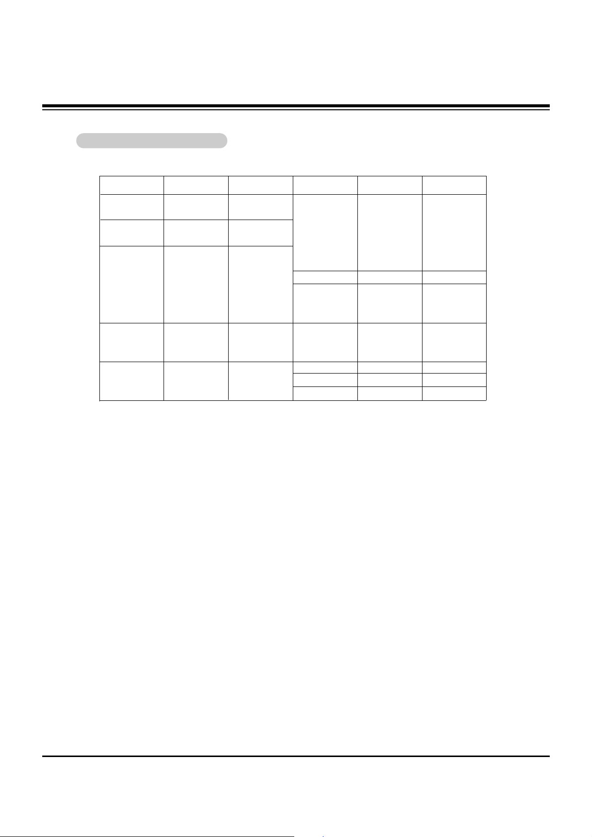
Display Specifications
Display Specifications
RGB/DVI Mode
Resolution
640x350
720x400
640x480
848x480
852x480
Horizontal
Frequency(KHz)
31.468
37.861
31.469
37.927
31.469
35.000
37.861
37.500
43.269
45.913
31.5
35
37.5
31.5
35
37.5
70.09
85.08
70.08
85.03
59.94
66.66
72.80
75.00
85.00
90.03
60.00
70.00
75.00
60.00
70.00
75.00
35.156
37.879
48.077
46.875
53.674
56.000
49.725
48.363
54.476
60.023
54.348
63.995
67.500
68.681
60.000
63.981
56.25
60.31
72.18
75.00
85.06
90.00
74.55
60.00
70.06
75.02
60.05
70.01
75.00
75.06
60.00
60.02
Vertical
Frequency(Hz)
Resolution
800x600
832x624
1024x768
1152x864
1152x870
1280x1024
Horizontal
Frequency(KHz)
Vertical
Frequency(Hz)
1280x960
SPECIFICATIONS
Page 9
- 9 -
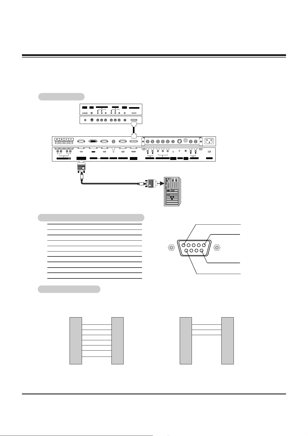
No. Pin name
1 No connection
2 RXD (Receive data)
3 TXD (Transmit data)
4 DTR (DTE side ready)
5 GND
6 DSR (DCE side ready)
7 RTS (Ready to send)
8 CTS (Clear to send)
9 No Connection
1
5
6
9
2
3
5
4
6
7
8
RXD
TXD
GND
DTR
DSR
RTS
CTS
TXD
RXD
GND
DSR
DTR
CTS
RTS
PC
7-Wire Configurations
(Standard RS-232C cable)
D-Sub 9
3
2
5
6
4
8
7
PDP
D-Sub 9
2
3
5
4
6
7
8
RXD
TXD
GND
DTR
DSR
RTS
CTS
TXD
RXD
GND
DTR
DSR
RTS
CTS
PC
3-Wire Configurations
(Not standard)
D-Sub 9
3
2
5
4
6
7
8
PDP
D-Sub 9
- Connect the RS-232C input jack to an external control device (such as a computer or an A/V control system)
and control the Plasma display’s functions externally.
- Connect the serial port of the control device to the RS-232C jack on the Plasma display back panel.
- RS-232C connection cables are not supplied with the Plasma display.
TType of Connector; D-Sub 9-Pin Male
ype of Connector; D-Sub 9-Pin Male
RS-232C Configurations
RS-232C Configurations
RS-232C Setup
RS-232C Setup
R
( )( )
( )
( )
L
EXPANDED
INPUT
VIDEO
INPUT
RS-232C INPUT
(CONTROL/SERVICE)
EXTERNAL SPEAKER
Y PBP
R
(MONO)
R
AUDIO
L
R
AUDIO
L
S-VIDEO
AC INPUT
AUDIO INPUT
AUDIO INPUT
AUDIO INPUT
REMOTE
CONTROL
DVI INPUT RGB INPUT
RGB OUTPUT
COMPONENT INPUT
(MONO)
R
AUDIO
VIDEO
L
AV(EXPANDED) INPUT
R
AUDIO
VIDEO
L
AV OUTPUT
EXPANDED OUTPUT
REMOTE
CONTROL
ANT INDC IN
(DC 12V)
+75 Ω
PC
EXTERNAL CONTROL DEVICE SETUP
Page 10
- 10 -
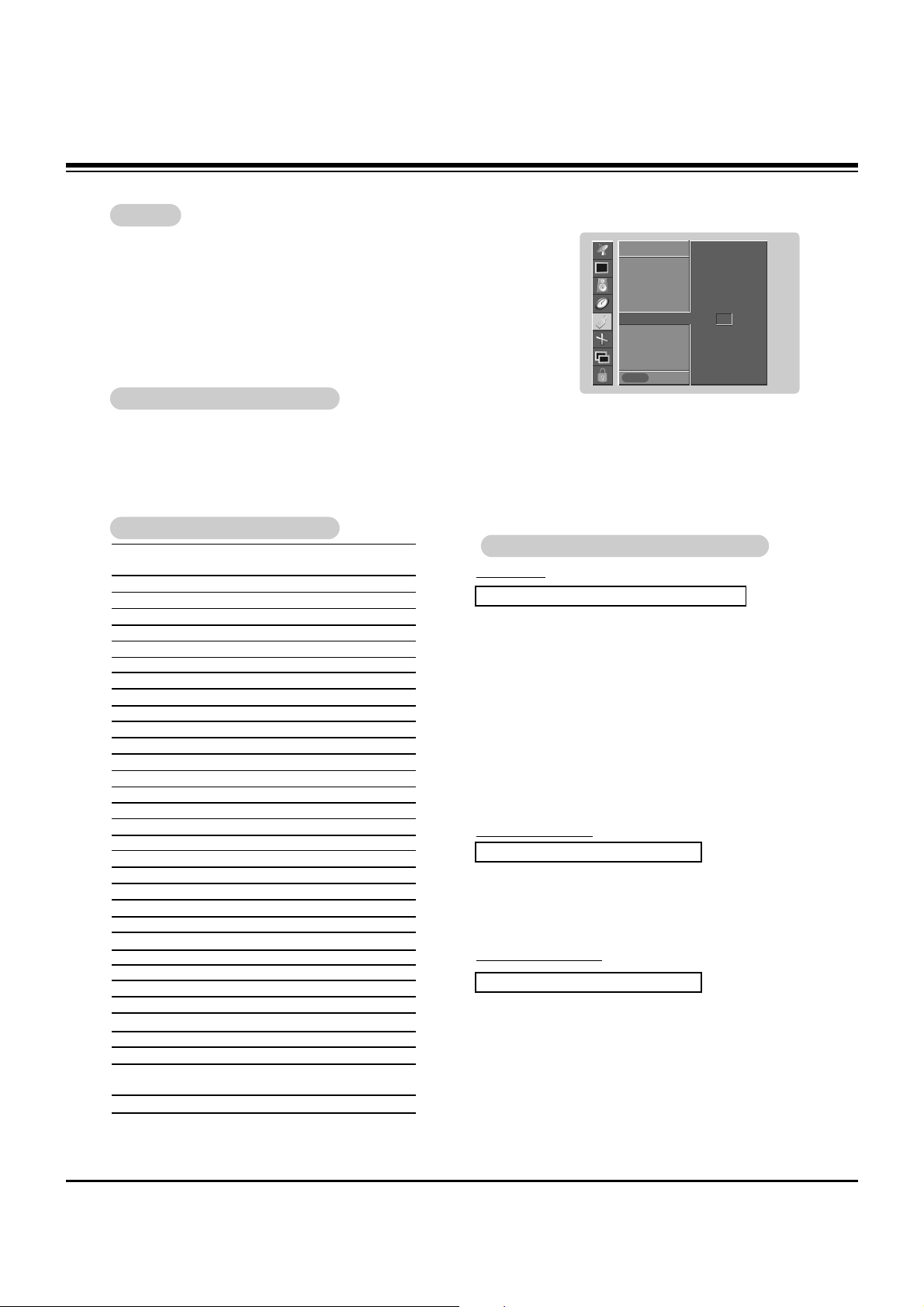
Set ID
Set ID
- Use this function to specify a plasma display ID number.
• Baud rate : 115200 bps (UART)
• Data length : 8 bits
• Parity : None
* Use a crossed (reverse) cable.
• Stop bit : 1 bit
• Communication code : ASCII code
Communication Parameters
Communication Parameters
1. Press the MENU button and then use
DD /EE
button to select the SPECIAL menu.
2. Press the GGbutton and then use
DD /EE
button to select Set ID.
3. Press the GGbutton and then use F / G button to adjust Set ID to choose the desired
plasma display ID number. The adjustment range of Set ID is 1 ~ 99.
4. Press the ENTER button to save.
SPECIAL
Prev.
Language
Key lock
ISM Method
Low power
Set ID
GG
Caption / Text
Captions
OSD Rotate
SPECIAL
MENU
1
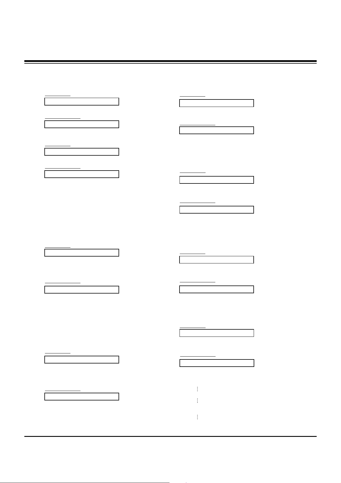
Transmission
*
[Command 1]: First command to control PDP set. (j or k)
*
[Command 2]: Second command to control PDP set.
*
[Set ID]: You can adjust the set ID to choose desired plasma
display ID number in Special menu. Adjustment
range is 1 ~ 99. When selecting Set ID ‘0’, every
connected PDP set is controlled. Set ID is indicated as decimal (1~99) on menu and as Hexa decimal (0x0~0x63) on transmission/receiving protocol.
*
[DATA]: To transmit command data.
Transmit ‘FF’ data to read status of command.
*
[Cr]: Carriage Return
ASCII code ‘0x0D’
*
[ ]: ASCII code ‘space (0x20)’
[Command1][Command2][ ][Set ID][ ][Data][Cr]
TTransmission / Receiving Protocol
ransmission / Receiving Protocol
OK Acknowledgement
* The Plasma display transmits ACK (acknowledgement)
based on this format when receiving normal data. At this
time, if the data is data read mode, it indicates present
status data. If the data is data write mode, it returns the
data of the PC computer.
[Command2][ ][Set ID][ ][OK][Data][x]
Error Acknowledgement
* The Plasma display transmits ACK (acknowledgement)
based on this format when receiving abnormal data from
non-viable functions or communication errors.
[Command2][ ][Set ID][ ][NG][Data][x]
Data 1: Illegal Code
2: Not supported function
3: Wait more time
01. Power k a 0 ~ 1
02. Input Select k b 0 ~ 6
03. Aspect Ratio k c 0 ~ 3
04. Screen Mute k d 0 ~ 1
05. Volume Mute k e 0 ~ 1
06. Volume Control k f 0 ~ 64
07. Contrast k g 0 ~ 64
08. Brightness k h 0 ~ 64
09. Color k i 0 ~ 64
10. Tint k j 0 ~ 64
11. Sharpness k k 0 ~ 64
12. OSD Select k l 0 ~ 1
13.
Remote Control Lock Mode
k m 0 ~ 1
14. PIP/Twin k n 0 ~ 3
15. PIP Size k o 0 ~ 1
16. Split Zoom k p 21 ~99
17. PIP Position k q 0 ~ 3
18. Treble k r 0 ~ 64
19. Bass k s 0 ~ 64
20. Balance k t 0 ~ 64
21. Color Temperature k u 0 ~ 3
22. Red Adjustment k v 0 ~ C8
23. Green Adjustment k w 0 ~ C8
24. Blue Adjustment k $ 0 ~ C8
25. PIP Input Source k y 0 ~ 6
26. Abnormal Status k z 0 ~ a
27. ISM Method j p 0 ~ 3
28. Low Power j q 0 ~ 1
29. Orbiter Time Setting j r 1 ~ FE
30. Orbiter Pixel Setting j s 0 ~9
31. Picture Size Setting j t 0 ~64
for Double Window mode
32. Auto Configure j u 1
COMMAND 1 COMMAND 2 DATA
(Hexadecimal)
• When setting the 27 ~ 32, a menu doesn’t display on
screen.
Command Reference List
Command Reference List
EXTERNAL CONTROL DEVICE SETUP
Page 11
- 11 -
02. Input Select (Command2:b) (Main Picture Input)
G To select input source for the Plasma display.
You can also select an input source using the INPUT
SELECT button on the Plasma display's remote control.
Transmission
Data 0 : RGB
1 : Component
2 : Video
3 : S-Video
4 : DVI
5 : TV
6 : Video (Exp.)
[k][b][ ][Set ID][ ][Data][Cr]
Acknowledgement
[b][ ][Set ID][ ][OK][Data][x]
01. Power (Command2:a)
G To control Power On/Off of the Plasma display.
Transmission
Data 0 : Power Off 1 : Power On
[k][a][ ][Set ID][ ][Data][Cr]
Acknowledgement
[a][ ][Set ID][ ][OK][Data][x]
G To show Power On/Off.
Transmission
[k][a][ ][Set ID][ ][FF][Cr]
Acknowledgement
Data 0 : Power Off 1 : Power On
* In a like manner, if other functions transmit ‘FF’ data
based on this format, Acknowledgement data feedback
presents status about each function.
[a][ ][Set ID][ ][OK][Data][x]
*
Real data mapping 1
0 : Step 0
A : Step 10 (SET ID 10)
F : Step 15 (SET ID 15)
10 : Step 16 (SETID 16)
64 : Step 100
05. Volume Mute (Command2:e)
G To control volume mute on/off.
You can also adjust mute using the MUTE button on
remote control.
Transmission
Data 0 : Volume mute on (Volume off)
1 : Volume mute off (Volume on)
[k][e][ ][Set ID][ ][Data][Cr]
Acknowledgement
[e][ ][Set ID][ ][OK][Data][x]
03. Aspect Ratio (Command2:c) (Main picture format)
G To adjust the screen format.
You can also adjust the screen format using the ARC
(Aspect Ratio Control) button on remote control or in the
Screen menu.
Transmission
Data 0 : Wide screen (16:9)
1 : Normal screen (4:3)
2 : Full screen (Zoom)
3 : Horizon
[k][c][ ][Set ID][ ][Data][Cr]
Acknowledgement
* Using the PC input, you select either 16:9 or 4:3 screen
aspect ratio.
[c][ ][Set ID][ ][OK][Data][x]
04. Screen Mute (Command2:d)
G To select screen mute on/off.
Transmission
Data 0 : Screen mute off (Picture on)
1 : Screen mute on (Picture off)
[k][d][ ][Set ID][ ][Data][Cr]
Acknowledgement
[d][ ][Set ID][ ][OK][Data][x]
06. Volume Control (Command2:f)
G To adjust volume.
You can also adjust volume with the volume buttons
on remote control.
Transmission
Data Min : 0 ~ Max : 64
• Refer to ‘Real data mapping 1’ as shown below.
[k][f][ ][Set ID][ ][Data][Cr]
Acknowledgement
[f][ ][Set ID][ ][OK][Data][x]
07. Contrast (Command2:g)
G To adjust screen contrast.
You can also adjust contrast in the Picture menu.
Transmission
Data Min : 0 ~ Max : 64
• Refer to ‘Real data mapping 1’ as shown below.
[k][g][ ][Set ID][ ][Data][Cr]
Acknowledgement
[g][ ][Set ID][ ][OK][Data][x]
EXTERNAL CONTROL DEVICE SETUP
Page 12

- 12 -
09. Color (Command2:i)
G To adjust the screen color.
You can also adjust color in the Video menu.
Transmission
Data Min : 0 ~ Max : 64
• Refer to ‘Real data mapping 1’. See page 34.
[k][i][ ][Set ID][ ][Data][Cr]
Acknowledgement
[i][ ][Set ID][ ][OK][Data][x]
10. Tint (Command2:j)
G To adjust the screen tint.
You can also adjust tint in the Video menu.
Transmission
Data Red : 0 ~ Green : 64
• Refer to ‘Real data mapping 1’. See page 34.
[k][j][ ][Set ID][ ][Data][Cr]
Acknowledgement
[j][ ][Set ID][ ][OK][Data][x]
08. Brightness (Command2:h)
G To adjust screen brightness.
You can also adjust brightness in the Video menu.
Transmission
Data Min : 0 ~ Max : 64
• Refer to ‘Real data mapping 1’. See page 34.
[k][h][ ][Set ID][ ][Data][Cr]
Acknowledgement
[h][ ][Set ID][ ][OK][Data][x]
13. Remote Control Lock Mode (Command2:m)
G To lock the remote control and the front panel controls on
the plasma display.
Transmission
[k][m][ ][Set ID][ ][Data][Cr]
Acknowledgement
Data 0: Lock off 1: Lock on
• If you’re not using the remote control, use this mode.
When main power is on/off, remote control lock is released.
[m][ ][Set ID][ ][OK][Data][x]
14. PIP / DW (Command2:n)
G To control the PIP(Picture-in-Picture)/DW (Double Window).
You can also control the PIP/DW using the PIPor DW button on the remote control or in the Special menu.
Transmission
Data 0: PIP/DW off
1: PIP
2: DW1
3: DW2
[k][n][ ][Set ID][ ][Data][Cr]
Acknowledgement
[n][ ][Set ID][ ][OK][Data][x]
G To adjust the screen sharpness.
You can also adjust sharpness in the Video menu.
Transmission
11. Sharpness (Command2:k)
Data Min: 0 ~ Max: 64
• Refer to ‘Real data mapping 1’. See page 34.
[k][k][ ][Set ID][ ][Data][Cr]
Acknowledgement
[k][ ][Set ID][ ][OK][Data][x]
12. OSD Select (Command2:l)
G To select OSD (On Screen Display) on/off.
Transmission
[k][l][ ][Set ID][ ][Data][Cr]
Acknowledgement
Data 0: OSD off 1: OSD on
[l][ ][Set ID][ ][OK][Data][x]
15. PIP Size (Command2:o)
G To select the PIPpicture format.
You can also select the PIP picture format using WIN.SIZE
on the remote control.
Transmission
[k][o][ ][Set ID][ ][Data][Cr]
Acknowledgement
Data 0: 4:3 1: 16:9
[o][ ][Set ID][ ][OK][Data][x]
16. Split Zoom (Command2:p)
G To operate split zoom function and select the split
zoom section number.
Transmission
Data Min: 21 ~ Max: 99
ex. Data 21: Selection 1 of 2 split zoom.
• Refer to ‘Real data mapping 2’.
[k][p][ ][Set ID][ ][Data][Cr]
Acknowledgement
[p][ ][Set ID][ ][OK][Data][x]
*
Real data mapping 2
21: Selection 1 of 2 split zoom
24: Selection 4 of 2 split zoom
41: Selection 1 of 4 split zoom
42: Selection 2 of 4 split zoom
44: Selection 4 of 4 split zoom
45: Selection 5 of 4 split zoom
91: Selection 1 of 9 split zoom
99: Selection 9 of 9 split zoom
EXTERNAL CONTROL DEVICE SETUP
Page 13

- 13 -
22. Red Adjustment (Command2:v)
G To adjust red in color temperature.
Transmission
Data Min: 0 ~ Max: C8
• Refer to ‘Real data mapping3’ as shown below.
[k][v][ ][Set ID][ ][Data][Cr]
Acknowledgement
[v][ ][Set ID][ ][OK][Data][x]
23. Green Adjustment (Command2:w)
G To adjust green in color temperature.
T
ransmission
Data Min: 0 ~ Max: C8
• Refer to ‘Real data mapping3’ as shown below.
[k][w][ ][Set ID][ ][Data][Cr]
Acknowledgement
[w][ ][Set ID][ ][OK][Data][x]
24. Blue Adjustment (Command2:$)
G To adjust blue in color temperature.
Transmission
Data Min: 0 ~ Max: C8
• Refer to ‘Real data mapping3’ as shown below.
[k][$][ ][Set ID][ ][Data][Cr]
Acknowledgement
[$][ ][Set ID][ ][OK][Data][x]
21. Color Temperature (Command2:u)
G To adjust color temperature.
You can also adjust ACC in the Video menu.
Transmission
Data 0: Normal 1: Cool 2: Warm 3: User
[k][u][ ][Set ID][ ][Data][Cr]
Acknowledgement
[u][ ][Set ID][ ][OK][Data][x]
20. Balance (Command2:t)
G To adjust balance.
You can also adjust balance in the Audio menu.
Transmission
Data Min: 0 ~ Max: 64
• Refer to ‘Real data mapping 1’. See page 34.
[k][t][ ][Set ID][ ][Data][Cr]
Acknowledgement
[t][ ][Set ID][ ][OK][Data][x]
18. Treble (Command2:r)
G To adjust treble.
You can also adjust treble in the Audio menu.
Transmission
Data Min: 0 ~ Max: 64
• Refer to ‘Real data mapping 1’. See page 34.
[k][r][ ][Set ID][ ][Data][Cr]
Acknowledgement
[r][ ][Set ID][ ][OK][Data][x]
19. Bass (Command2:s)
G To adjust bass.
You can also adjust bass in the Audio menu.
Transmission
Data Min: 0 ~ Max: 64
• Refer to ‘Real data mapping 1’. See page 34.
[k][s][ ][Set ID][ ][Data][Cr]
Acknowledgement
[s][ ][Set ID][ ][OK][Data][x]
17. PIP Position (Command2:q)
G To select sub picture position for PIP.
You can also adjust the sub picture position using
WIN.POSITION on the remote control or in the Special menu.
Transmission
Data 0: Right down on screen
1: Left down on screen
2: Left up on screen
3: Right up on screen
[k][q][ ][Set ID][ ][Data][Cr]
Acknowledgement
[q][ ][Set ID][ ][OK][Data][x]
*
Real data mapping 3
0 : -20
5 : -19
A : -18
5F: -1
64: 0
69: +1
C3: +19
C8: +20
EXTERNAL CONTROL DEVICE SETUP
Page 14

- 14 -
EXTERNAL CONTROL DEVICE SETUP
27. ISM Method (Command2:p)
G To avoid having a fixed image remain on screen.
Transmission
Data 0: Normal
1: White wash
2: Orbiter
3: Inversion
[j][p][ ][Set ID][ ][Data][Cr]
Acknowledgement
[p][ ][Set ID][ ][OK][Data][x]
28. Low Power (Command2:q)
G To control the low power function on/off.
Transmission
Data 0: Low power off
1: Low power on
[j][q][ ][Set ID][ ][Data][Cr]
Acknowledgement
[q][ ][Set ID][ ][OK][Data][x]
29. Orbiter Time Setting (Command2:r)
G To adjust orbiter operation time term.
Transmission
Data Min: 1 ~ Max: FE
• Refer to ‘Real data mapping1’. See page 34.
[j][r][ ][Set ID][ ][Data][Cr]
Acknowledgement
[r][ ][Set ID][ ][OK][Data][x]
30. Orbiter Pixel Setting (Command2:s)
G To adjust pixel number in orbiter function.
Transmission
Data Min: 0 ~ Max: 9
[j][s][ ][Set ID][ ][Data][Cr]
Acknowledgement
[s][ ][Set ID][ ][OK][Data][x]
31. Picture Size Setting for Double Window
mode (Command2:t)
G To adjust main window size in Double Window mode.
Transmission
Data Min: 0 ~ Max: 64
• Refer to ‘Real data mapping1’. See page 30.
[j][t][ ][Set ID][ ][Data][Cr]
Acknowledgement
[t][ ][Set ID][ ][OK][Data][x]
32. Auto Configure (Command2:u)
G To adjust picture position and minimize image shaking
automatically. It works only in RGB (PC) mode.
Transmission
Data 1: To set
[j][u][ ][Set ID][ ][Data][Cr]
Acknowledgement
[u][ ][Set ID][ ][OK][Data][x]
25. PIP Input Select (Command2:y)
G To select input source for sub picture in PIP mode.
Transmission
Data 0 : RGB
1 : Component
2 : Video
3 : S-Video
4 : DVI
5 : TV
6 : Video (Exp.)
[k][y][ ][Set ID][ ][Data][Cr]
Acknowledgement
[y][ ][Set ID][ ][OK][Data][x]
26. Abnormal State (Command2:z)
G To recognize an abnormal state.
Transmission
Data 0: Normal (Power on and signal exist)
1: No signal (Power on)
2: Turn the monitor off by remote control
3: Turn the monitor off by sleep time function
4: Turn the monitor off by RS-232C function
5: 5V down
6: AC down
7: Turn the monitor off by Fan Alarm function
8: Turn the monitor off by off time function
9: Turn the monitor off by auto off function
a: Turn the monitor off by AV board detect
Data FF:Read
[k][z][ ][Set ID][ ][FF][Cr]
Acknowledgement
[z][ ][Set ID][ ][OK][Data][x]
Page 15

- 15 -
IR Code(NEC Format)
G Connect your wired remote control to the Remote port on the Plasma display.
G Output waveform
Single pulse, modulated with 37.917KHz signal at 455KHz
G Configuration of frame
G Repeat code
G Lead code
• 1st frame
Low
custom code
Lead
code
High
custom code
Data code
Data code
T
C
Tf
T1
C0
Carrier frequency
F
CAR = 1/TC = fOSC/12
Duty ratio = T1/T
C = 1/3
• Repeat frame
C1 C2 C3 C4 C5 C6 C7 C0 C1 C2 C3 C4 C5 C6 C7 D0 D1 D2 D3 D4 D5 D6 D7 D0 D1 D2 D3 D4 D5 D6 D7
Repeat code
9 ms 4.5 ms
0.55 ms
9 ms
2.25 ms
G Bit description
G Frame interval : Tf
The waveform is transmitted as long as a key is depressed.
• Bit “0”
Tf Tf
Tf=108ms @455KHz
0.56 ms 0.56 ms
1.12 ms
• Bit “1”
2.24 ms
How to Connect
How to Connect
Remote Control IR Code (NEC Format)
Remote Control IR Code (NEC Format)
Page 16

- 16 -
IR Code(NEC Format)
UP (D)
DOWN (
E
)
VOL+ (
G)
VOL- (
F)
POWER ON/OFF
POWER ON
POWER OFF
MUTE
Number Key 0
Number Key 1
Number Key 2
Number Key 3
Number Key 4
Number Key 5
Number Key 6
Number Key 7
Number Key 8
Number Key 9
INPUT SELECT
MULTIMEDIA
RGB
DVI
Component
Video
S-video
TV
Video (Exp.)
SLEEP
ENTER (
ç)
MENU
DASP
APC
PIP
PIP INPUT
SWAP
PIP ARC
TWIN PICTURE
ZOOM +
ZOOM Window Size
Window Position
Split Zoom
ARC
ARC (4:3)
ARC (16:9)
ARC (Zoom)
AUTO CONFIG
AUTO PROGRAM
MEMORY/ERASE
FAVORITE CH
CAPTION
MTS
PIP UP (
D
)
PIP DOWN (
E
)
00H
01H
02H
03H
08H
C4H
C5H
09H
10H
11H
12H
13H
14H
15H
16H
17H
18H
19H
0BH
98H
D5H
C6H
BFH
5AH
D8H
D6H
D0H
0EH
44H
43H
52H
4DH
60H
61H
63H
64H
6BH
40H
41H
69H
6AH
7BH
79H
76H
77H
AFH
99H
54H
55H
1EH
39H
0AH
71H
72H
R/C Button
R/C Button
R/C Button
R/C Button
R/C Button (Power On/Off)
Discrete IR Code (Only Power On)
Discrete IR Code (Only Power Off)
R/C Button
R/C Button
R/C Button
R/C Button
R/C Button
R/C Button
R/C Button
R/C Button
R/C Button
R/C Button
R/C Button
R/C Button (Video/S-video/Component/RGB/DVI)
R/C Button (Component/RGB/DVI)
Discrete IR Code (Input RGB Selection)
Discrete IR Code (Input DVI Selection)
Discrete IR Code (Input Component Selection)
Discrete IR Code (Input Video Selection)
Discrete IR Code (Input S-video Selection)
Discrete IR Code (Input TV Selection)
Discrete IR Code (Input Expanded Video Selection)
R/C Button
R/C Button
R/C Button
R/C Button
R/C Button
R/C Button
R/C Button
R/C Button (PIP/TWIN picture Exchange)
R/C Button (4:3/16:9)
R/C Button
R/C Button
R/C Button
R/C Button
R/C Button
R/C Button
R/C Button (4:3/16:9/Zoom mode Selection)
Discrete (Only 4:3 mode)
Discrete (Only 16:9 mode)
Discrete (Only Zoom mode)
Discrete IR Code
R/C Button
R/C Button
R/C Button
R/C Button
R/C Button
R/C Button
R/C Button
Code (Hexa) Function Note
Page 17

1. Application
These instructions apply to the P42W34 PDP monitor.
2. Notes
(1) Because this is not a hot chassis, it is not necessary to use
an isolation transformer. However, the use of isolation
transformer will help protect test instruments.
(2) Adjustments must be performed in the correct order.
(3) The adjustments must be performed in conditions between
68° and 86°F with 55-75% relative humidity.
(4) The input voltage of the receiver must keep at 100~240V,
50/60Hz during adjustment(s).
(5) The receiver must be operated for at least 15 minutes prior
to the adjustment(s).
1) The receiver must be operated receiving 100% white
pattern, prior to adjustment(s).
(White condition in HEAT-RUN mode)
2) Enter into HEAT-RUN mode
- Press the POWER ON KEY on Adjustment R/C.
- OSD display HEAT-RUN WHITE and screen display
100% full WHITE PATTERN.
[ Set is activated HEAT-RUN without signal generator in
this mode.
[ Single color pattern of HEAT-RUN mode uses to check
PANEL. (RED/BLUE/GREEN)
[Caution]
If you turn on a still screen more than 20 minutes
(such as Cross Hatch Pattern, Digital Pattern), an
afterimage may be occur in the black level part of the
screen. (Image Burn)
O
Data values, adjusted in the board, are valid until the VSC
Board is dissued and must be protected. For the protection of
data, Micom does not permit any more adjustments after
completion.
O
In case of re-adjustment, operate First Value Setting.
Each PCB Assy must be checked prior to installation.
(Especially, be careful Power PCB Assy which can cause
damage to PDP Module.)
3. POWER PCB Assy Voltage
Adjustments
(Va, Vs Voltage Adjustments)
3-1 Test Equipment : Digital Multi-Meter (DMM)
3-2 Connection Diagram for Measuring
Refer to Fig 1.
3-3 Adjustment Method
(1) Va Adjustment
1) Select White Mode of HEAT RUN or receive a 100%
Full White Pattern with the Video/RGB from a Pattern
Generator.
2) Connect the + terminal of the DMM to Va pin of P805
and the - terminal of the DMM to GND pin of P805.
3) Adjust RV601 until the reading of Va on the DMM is the
same as Va voltage on label of panel Right/Top.
(Deviation : ±0.5V)
(2) Vs adjustment
1) Connect the + terminal of the DMM to Vs pin of P805
and the - terminal of the DMM to GND pin of P805.
2) Adjust RV401 until the reading of Vs on the DMM is the
same as Vs voltage on label of panel Right/Top.
(Deviation : ±0.5V)
4. Auto ADC Adjustments
4-1 RGB Auto Offset & Gain Adjustment
(1) Input Half Black/White (255 Gray) signal from a Pattern
Generator into the RGB Input.
(XGA 1024*768 60Hz)
- 17 -
ADJUSTMENT INSTRUCTIONS
DMM
+ -
RV401
Vs ADJ
RV601
Va ADJ
P804
P805
Vs
NC
Va
GND
DMM
+ --
RV401
Vs ADJ
RV601
Va ADJ
P804
P805
RV401
Vs ADJ
RV601
Va ADJ
P804
P805
Vs
NC
Va
GND
Vs
NC
Va
GND
<Fig 1> Connection Diagram of Power Adjustments
Page 18

- 18 -
(2) Press POWER ON KEY on the Adjustment R/C and select
RGB Cut.
(3) Press Vol. + key and operate TO SET(Black).
(4) Original Half Black/White(255 Gray) screen will be
presented about 5~10 seconds later. And Cursor moves
with a lower part Y-cut.
This case RGB Auto Offset, MAX Gain adjustment will be
completed.
4-2 Component Auto Offset & Gain
Adjustment
(Y, Pb, Pr Adjustment)
(1) Input Half Black/White (255 Gray) signal from a Pattern
Generator into the component Input. (1280*720p 60Hz)
(2) Press Vol. + key and operate To SET from the condition
where the cursor moves with the Y-cut.
(3) Original Half White(255 Gray) screen will be presented
about 5~10 seconds later. And Cursor moves with a lower
part Pb-cut.
This case Component Y-offset & Gain adjustment will be
completed.
(4) After adjustment of item (3), receive Half Blue(127 level)
signal for Pb-offset adjustment.
(5) Press Vol. + key and operate To SET for Pb-offset
adjustment.
(6) Original Half Blue(127 level) screen will be presented
about 5~10 seconds later. And Cursor moves with a lower
part Pr-cut.
This case Component Pb-offset & Gain adjustment will be
completed.
(7) After adjustment of item (5), receive Half Red(127 level)
signal for Pr-offset adjustment.
(8) Press Vol. + key and operate To SET for Pr-offset
adjustment.
(9) Original Half Red(127 level) screen will be presented
about 5~10 seconds later and the OK indication appears.
This case Component Auto offset & Gain adjustment will
be completed.
O
You can check whether circuit adjustment is correct or not,
below. (Item 4-1)
(1) Display RGB to the Main picture, CVBS to the Sub picture
in TWIN PICTURE mode. (DOUBLE WINDOW)
(2) To check the Offset, input Full Black (0 gray) signal into
CVBS and RGB input part at the same time in the Pattern
Generator.
(3) To check the MAX-Gain, input Full White (255 gray) signal
into CVBS and RGB input part at the same time in the
Pattern Generator.
(4) Visually compare Black and White Levels. If there is no
Level difference, then the adjustment is correct.
O
You can check whether circuit adjustment is correct or not,
below. (Item 4-2)
(1) Display Component to the Main picture, CVBS to the Sub
picture in TWIN PICTURE mode. (DOUBLE WINDOW)
(2) Using HD STB(SK-010T) or equal equipment input Digital
Pattern into CVBS and Component input part.
(720p or 1080i)
(3) Visually compare Black and White Levels of Main and Sub
screen. If there is no Level difference, then the adjustment
is correct.
ADJUSTMENT INSTRUCTIONS
White : 255 Gray level
White : 255 Gray level
Page 19

- 19 -
5. Adjustment of White Balance
5-1. Required Equipment
Color analyzer (CA-100 or similar product)
5-2. Connection Diagram of Equipment for
Measuring
(Manual Adjustment)
5-3. Adjustment of White Balance
O
Operate the Zero-calibration of the CA-100, then apply the
sensor to the PDP display surface.
O
Manual adjustment is also possible with the following sequence.
(1) Select WHITE PATTERN of HEAT RUN mode by pressing
POWER ON KEY on the Adjustment R/C, then operate the
HEAT RUN for at least 15 minutes.
(2) Supply 216Gray, 50% size length and breadth signal to RGB
input. (Refer to Fig 2)
(3) W/B adjustment must be adjusted only High Light and then
save the adjustment value with
Y Key.
(4) To adjust High Light, apply sensor to 216 Gray Level (or 105-
115 Cd/m
2
) Pattern, press ADJ Key on Adjustment R/C and
press T, U on Adjustment R/C to select R-L or G-L, press
VOL +, - Key(s) to adjustuntil color coordination becomes as
below.
X: 0.280±0.003, Y: 0.290±0.003
Color temperature: 10,000°K±500°K
(5) Exit adjustment mode using Y Key.
6. DDC Data Input
6-1. Required Test Equipment
(1) A jig for adjusting PC, DDC. (PC serial to D-sub.
Connection equipment)
(2) S/W for writing DDC(EDID data write & read)
(3) D-Sub 15P cable, D-Sub to DVI Connector (DVI-D)
6-2. Setting of Device
6-3. Preparation for Adjustments
(1) Set devices as above and turn the PC, JIG on.
(2) Open S/W for writing DDC (EDID data write & read).
(operated in DOS mode)
6-4. Sequence of Adjustments
(1) DDC Data Input for Analog-RGB
1) Place the set on the table and turn the power on.
2) Connect PC Serial to D-sub 15P Cable of JIG for DDC
Adjustment to RGB terminal (D-Sub 15Pin).
3) Open S/W for DDC record and select DDC Data for
Analog RGB in Model Menu.
4) Operate EDID Write command.
5) Operate EDID Read command and check whether
Check Sum is OK.
6) If Check Sum is NG, repeat 3) ~ 4).
7) If Check Sum is OK, DDC Data for Analog-RGB input is
completed.
(2) DDC Data input for Digital-RGB
1) Connect PC Serial to DVI Cable(DVI-D) of JIG for DDC
Adjustment to DVI terminal.
2) Operate S/W for DDC record and select DDC Data for
Digital RGB in Model Menu.
3) Operate EDID Write command.
4) Operate EDID Read command and check whether
Check Sum is OK.
5) If Check Sum is NG, repeat 3) ~ 4).
6) If Check Sum is OK, DDC Data for Digital-RGB input is
completed.
ADJUSTMENT INSTRUCTIONS
R-H 216R-H 216
G-H 216G-H 216
Window
VG828, MSPG-2100
or MSTG-5200
High Light
216 Gray Level
<Fig 2> Connection Diagram of Manual Adjustment
RGB Signal Input
PDP MONITOR
Page 20

- 20 -
BLOCK DIAGRAM
Page 21

- 21 -
BLOCK DIAGRAM
Page 22

- 22 -
1. Screws marked (a) hold the Plate Assembly in place (Plate A/V).
2. Screws marked (b) connect Plate Assembly with Back Cover Assembly.
3. Screws marked with an arrow connect Back Cover Assembly & Outer Assembly to Main Frame.
NOTE> All three Assemblies should be removed in disassembly.
ASSEMBLY METHOD
Page 23

- 23 -
NOTES
Page 24

- 24 -
EXPLODED VIEW
<Tuner>
720
710
700
200
203
205
202
204
206
530
401
540
541
520
560
400
410
550
210
301
300
305
570
553
521
551
552
201
580
220
Page 25

- 25 -
EXPLODED VIEW PARTS LIST
200 6348Q-E036A PDP,42 16:9 852*480 PDP42V50000(KK MODEL), FOR INTERCOMPANY
201 6871QDH051A PCB ASSEMBLY,DISPLAY YDRV ASSY 42SD5_YDRV_TOP_TI_4LAYER
202 6871QDH052A PCB ASSEMBLY,DISPLAY YDRV ASSY 42SD5_YDRV_BTM_TI_4LAYER
203 6871QCH025A PCB ASSEMBLY,DISPLAY CTRL ASSY 42SD5 CTRL BD(LPCMC1121)
204 6871QYH027A PCB ASSEMBLY,DISPLAY YSUS ASSY 42SD5_SEPERATED_YSUS
205 6871QRH034A PCB ASSEMBLY,DISPLAY XRRT ASSY 42SD5_XR_SEPERATE(4 LAYER)
206 6871QZH030A PCB ASSEMBLY,DISPLAY ZSUS ASSY 42SD5(YZ SEPARATE)
210 4980V00460A SUPPORTER,VERTICAL MN-42PZ40
220 4980V00464B SUPPORTER
300 3091V00B01Y CABINET ASSEMBLY,RU-42PZ44 NON RF03GA
301 3110V00229A CASE ASSY,MN-42PZ40 NON NON
305 3790V00281E FILTER(MECH),MN-42PZ40S 1142G03E GLASS NBK MESH SINGLE AR
400 3809V00A47G BACK COVER ASSEMBLY,MU-42PZ44 NON PIGGY BACK
401 3301V00010G PLATE ASSEMBLY,A/V 3300V00205D MZ-42PZ44 PIGGY
410 3809V00A58F BACK COVER ASSEMBLY,MZ-42PZ44 NON KK MODULE
520 6871VMMP39A PCB ASSEMBLY,MAIN RF03GA MU-42PZ44 VSC
521 4980V00793A SUPPORTER,VSC EGI MZ-42PZ44
530 6871VSMU44A PCB ASSEMBLY,SUB CONT RF03GA MU-42PZ44
540 6871VSMV04A PCB ASSEMBLY,SUB PSW RF03GA MU-42PZ44
541 5020V00666A BUTTON,POWER MN-42PZ40 SET
550 6871VSMU98A PCB ASSEMBLY,SUB A/V RF03GA FIX B/D
551 4980V00465D SUPPORTER,AV INTERFACE SBHG MU-42PZ41
552 4980V00748C SUPPORTER,AV INTERFACE AL MN-42PZ44 ASSY
553 4814V00309B SHIELD,COVER RJ-42PZ40 RF02KC AL AC SOCKET
560 6871VSMU45A PCB ASSEMBLY,SUB SPK RF03GA MU-42PZ44
570 6871VSMU46A PCB ASSEMBLY,SUB A/V RF03GA MU-42PZ44 PACK ASSY
580 3501V00148A BOARD ASSEMBLY,POWER MU42PZ44 RF03GA SRX-74 SONY 42KK
700 3110V00237F CASE,TUNER RT-BA50 EGI BOTTOM ASSY
710 6871VSMX52A PCB ASSEMBLY,SUB VIDEO RF03GA PIGGY BACK(RU)
720 3110V00242F CASE,TUNER RT-BA50 EGI TOP ASSY
No.
Part No.
Description
Page 26

- 26 -
REPLACEMENT PARTS LIST
LOCA. NO PART NO DESCRIPTION
IC704
IC740
IC741
IC742
IC743
IC744
IC746
IC747
IC748
IC749
IC750
IC751
IC802
IC850
IC851
IC853
IC857
IC858
IC859
IC901
IC902
IC903
IC904
IC917
IC008
IC009
IC203
IC204
Q001
Q001
Q001
Q001
Q002
Q002
Q002
Q002
Q003
Q003
Q003
Q004
Q004
Q005
Q006
Q007
Q008
Q009
0IMCRAL006A
0IMCRPH017A
0IMCRFA013A
0IMCRFA013A
0ITI745740M
0IMCRPH017A
0IMCRPH015A
0IMCRPH016A
0IMCRPH014A
0IKE702700D
0IDS232000A
0IPH858400A
0ISA428200A
0IMCRSJ001A
0IPRPML001A
0IMCRRH001A
0IMCRRH001A
0IMCRSH001A
0IMCRSH001A
0IMCRMN014A
0IKE780800J
0IMCRSH001A
0IKE704200J
0IFA742530B
0TR830009BA
0TR830009BA
0TR830009BA
0TR830009BA
0TR150400BA
0TR387500AA
0TR387500AA
0TR387500AA
0TR150400BA
0TR387500AA
0TR387500AA
0TR387500AA
0TR150400BA
0TR387500AA
0TR387500AA
0TR387500AA
0TR387500AA
0TR387500AA
0TR387500AA
0TR387500AA
0TR387500AA
0TR387500AA
AT24C16AN10SI2.7 8P SOIC R/TP EEPROM
74LVC574APW 20P SOT3601
74LCX244MTC 20P LOW VOLTAGE BUFFER
74LCX244MTC 20P LOW VOLTAGE BUFFER
SN74HC574NSR 14P
74LVC574APW 20P SOT3601
74LVC32AD 14P SOT1081
74LVC139D 16P SOT1091
74LV132D 14P SOT1081
KIA7027AF 3, SOT89 TP RESET IC 2.7V
DS232AS 16P,SOP TP RS232
PCF8584T 20P IIC BUS CONTROLLER
LA4282 12S 2CHX10W AUDIO AMP
SC1565IST1.8 3P SOT223
MIC39100 3P SOT223
BA033FP ROHM 3PSOP
BA033FP ROHM 3PSOP
PQ05DZ1U 5, SMD
PQ05DZ1U 5, SMD
MSP3440G QA B8 V3 80 SOUND IC
KIA7808API 3 ST REGULATOR .
PQ05DZ1U 5, SMD
KIA7042AF SOT89 TP 4.2V
74ACT253SC 16PSOIC
BSS83
BSS83
BSS83
BSS83
CHIP 2SA1504S(ASY) KEC
CHIP 2SC3875S(ALY) KEC
CHIP 2SC3875S(ALY) KEC
CHIP 2SC3875S(ALY) KEC
CHIP 2SA1504S(ASY) KEC
CHIP 2SC3875S(ALY) KEC
CHIP 2SC3875S(ALY) KEC
CHIP 2SC3875S(ALY) KEC
CHIP 2SA1504S(ASY) KEC
CHIP 2SC3875S(ALY) KEC
CHIP 2SC3875S(ALY) KEC
CHIP 2SC3875S(ALY) KEC
CHIP 2SC3875S(ALY) KEC
CHIP 2SC3875S(ALY) KEC
CHIP 2SC3875S(ALY) KEC
CHIP 2SC3875S(ALY) KEC
CHIP 2SC3875S(ALY) KEC
CHIP 2SC3875S(ALY) KEC
LOCA. NO PART NO DESCRIPTION
IC001
IC001
IC002
IC002
IC003
IC005
IC006
IC101
IC102
IC103
IC104
IC1102
IC1104
IC1201
IC1202
IC1203
IC1204
IC1205
IC1401
IC1405
IC1406
IC201
IC202
IC301
IC301
IC302
IC401
IC401
IC402
IC402
IC403
IC403
IC404
IC405
IC405
IC407
IC410
IC415
IC501
IC502
IC503
IC504
IC601
IC701
IC702
IC703
0IZZVC0053A
0ISO208900A
0IAL241610B
0IMCRFA010A
0IFA753307A
0IMCRTI003A
0ISO211900A
0IAL242110A
0IAL242110A
0IMCRTI003A
0IPRPBB005A
0IMCRPH015A
0ISH122100B
0IMCRTI021A
0IMCRTI021A
0IMCRTI021A
0IMCRTI021A
0IMCRTI021A
0IIT323000E
0IMCRGN001B
0IMMRHY033A
0ISO208900A
0IMCRS5003A
0IMCRAD003A
0IMCRMN014A
0IKE704200J
0IIT323000E
0ITK118100B
0ISA715100D
0IMCRFA010A
0IFA741230A
0IMCRFA009A
0IMCRSH001A
0IMCRGN001B
0IMCRSH001A
0IMMRHY033A
0IMMRNE002A
0ISA715100D
0IMCROT001A
0IMMRHY033A
0IMMRHY033A
0IMMRHY033A
0IS5160000A
0IMCRRS001A
0IMMRSS064A
0IMMRMR006B
M37136EFSP 52P BK MICOM MU42PZ44 VSC
CXA2089Q 48QFP BK A/V SWITCH
AT24C16A10PI2.7 8PIN
KA7809R 2P DPAK
KA75330ZTA 3P,TO92 TP 3.3V
SN74HCT08D 16P R/TP QUADRUPLE
CXA2119M 28P,SOP TP VIDEO
AT24C2110SI2.5 8P,SOP TP 1K EEPROM
AT24C2110SI2.5 8P,SOP TP 1K EEPROM
SN74HCT08D 16P R/TP QUADRUPLE
OPA3692IDBQ 16PIN BUFFER AMP
74LVC32AD 14P SOT1081
PQ12RD21 4SIP ST REGULATOR
SN74LVTH541PWR 20P
SN74LVTH541PWR 20P
SN74LVTH541PWR 20P
SN74LVTH541PWR 20P
SN74LVTH541PWR 20P
VPC3230D C5 80P VIDEO PROCESSOR
FLI2310BC 208P DIGITAL VIDEO
HY57V643220C(L)T6 86P 64M
CXA2089Q 48QFP BK A/V SWITCH
SIL169 CL100 100P TMDS RX PANEL LINK
AD9888KS140 128P A/D CONVERTER IC
MSP3440G QA B8 V3 80 SOUND IC
KIA7042AF SOT89 TP 4.2V
VPC3230D C5 80P VIDEO PROCESSOR PDP50
TK11840L 8P SOT23L DCDC CONVERTER
LA7151M 10SOP R/TP AUDIO SW
KA7809R 2P DPAK
DM74LS123MX 16SOP
KA78M08RTM 2P DPAK
PQ05DZ1U 5, SMD TYPE R/TP REGULATOR
FLI2310BC 208P DIGITAL VIDEO
PQ05DZ1U 5, SMD TYPE R/TP REGULATOR
HY57V643220C(L)T6 86P 64M
UPD64083GF3BA 100 3D YC
LA7151M 10SOP R/TP AUDIO SW
REMBRANT1A 352BALL
HY57V643220C(L)T6 86P 64M
HY57V643220C(L)T6 86P 64M
HY57V643220C(L)T6 86P 64M
SII160 100 DIGITAL TRANSMITTER
R8820LV RDC 100P 16BIT
K6R4016V1DTC10 44P TSOP2400BF
MX29LV160ATTC70 48P 16M
IC
TRANSISTOR
RUN DATE : 2003.8.13
For Capacitor & Resistors, the
charactors at 2nd and 3rd digit
in the P/No. means as follows;
CC, CX, CK, CN : Ceramic
CQ : Polyestor
CE : Electrolytic
RD : Carbon Film
RS : Metal Oxide Film
RN : Metal Film
RF : Fusible
Page 27

- 27 -
LOCA. NO PART NO DESCRIPTION
Q101
Q1425
Q1473
Q200
Q201
Q201
Q202
Q203
Q204
Q204
Q205
Q205
Q206
Q206
Q207
Q207
Q208
Q209
Q211
Q251
Q252
Q253
Q301
Q302
Q303
Q304
Q305
Q401
Q410
Q411
Q412
Q413
Q414
Q415
Q416
Q417
Q418
Q419
Q420
Q421
Q422
Q423
Q424
Q450
Q471
Q472
Q473
Q474
Q475
Q476
Q477
0TR387500AA
0TR387500AA
0TR387500AA
0TR387500AA
0TR387500AA
0TR387500AA
0TR387500AA
0TR387500AA
0TR387500AA
0TR387500AA
0TR387500AA
0TR387500AA
0TR387500AA
0TR150400BA
0TR387500AA
0TR387500AA
0TR387500AA
0TR387500AA
0TR387500AA
0TR150400BA
0TR387500AA
0TR387500AA
0TR387500AA
0TR387500AA
0TR387500AA
0TR387500AA
0TR387500AA
0TR387500AA
0TR150400BA
0TR150400BA
0TR387500AA
0TR150400BA
0TR150400BA
0TR150400BA
0TR387500AA
0TR150400BA
0TR387500AA
0TR387500AA
0TR150400BA
0TR387500AA
0TR150400BA
0TR387500AA
0TR150400BA
0TR387500AA
0TR387500AA
0TR387500AA
0TR387500AA
0TR387500AA
0TR387500AA
0TR150400BA
0TR387500AA
CHIP 2SC3875S(ALY) KEC
CHIP 2SC3875S(ALY) KEC
CHIP 2SC3875S(ALY) KEC
CHIP 2SC3875S(ALY) KEC
CHIP 2SC3875S(ALY) KEC
CHIP 2SC3875S(ALY) KEC
CHIP 2SC3875S(ALY) KEC
CHIP 2SC3875S(ALY) KEC
CHIP 2SC3875S(ALY) KEC
CHIP 2SC3875S(ALY) KEC
CHIP 2SC3875S(ALY) KEC
CHIP 2SC3875S(ALY) KEC
CHIP 2SC3875S(ALY) KEC
CHIP 2SA1504S(ASY) KEC
CHIP 2SC3875S(ALY) KEC
CHIP 2SC3875S(ALY) KEC
CHIP 2SC3875S(ALY) KEC
CHIP 2SC3875S(ALY) KEC
CHIP 2SC3875S(ALY) KEC
CHIP 2SA1504S(ASY) KEC
CHIP 2SC3875S(ALY) KEC
CHIP 2SC3875S(ALY) KEC
CHIP 2SC3875S(ALY) KEC
CHIP 2SC3875S(ALY) KEC
CHIP 2SC3875S(ALY) KEC
CHIP 2SC3875S(ALY) KEC
CHIP 2SC3875S(ALY) KEC
CHIP 2SC3875S(ALY) KEC
CHIP 2SA1504S(ASY) KEC
CHIP 2SA1504S(ASY) KEC
CHIP 2SC3875S(ALY) KEC
CHIP 2SA1504S(ASY) KEC
CHIP 2SA1504S(ASY) KEC
CHIP 2SA1504S(ASY) KEC
CHIP 2SC3875S(ALY) KEC
CHIP 2SA1504S(ASY) KEC
CHIP 2SC3875S(ALY) KEC
CHIP 2SC3875S(ALY) KEC
CHIP 2SA1504S(ASY) KEC
CHIP 2SC3875S(ALY) KEC
CHIP 2SA1504S(ASY) KEC
CHIP 2SC3875S(ALY) KEC
CHIP 2SA1504S(ASY) KEC
CHIP 2SC3875S(ALY) KEC
CHIP 2SC3875S(ALY) KEC
CHIP 2SC3875S(ALY) KEC
CHIP 2SC3875S(ALY) KEC
CHIP 2SC3875S(ALY) KEC
CHIP 2SC3875S(ALY) KEC
CHIP 2SA1504S(ASY) KEC
CHIP 2SC3875S(ALY) KEC
LOCA. NO PART NO DESCRIPTION
Q478
Q479
Q720
Q721
Q722
Q723
Q724
Q725
D001
D001
D001
D002
D003
D004
D006
D011
D074
D075
D079
D100
D101
D102
D105
D106
D108
D109
D110
D111
D112
D113
D114
D115
D117
D118
D253
D254
D301
D302
D303
D304
D402
D404
D421
D422
D423
D854
D855
D857
D870
0TR104009AF
0TR387500AA
0TR387500AA
0TR387500AA
0TR387500AA
0TR150400BA
0TR387500AA
0TR387500AA
0DD184009AA
0DD226239AA
0DL200000CA
0DD184009AA
0DD184009AA
0DD184009AA
0DD226239AA
0DD226239AA
0DD100009AC
0DD100009AC
0DD184009AA
0DD226239AA
0DD226239AA
0DD226239AA
0DD226239AA
0DD226239AA
0DD226239AA
0DD226239AA
0DD226239AA
0DD226239AA
0DD226239AA
0DD226239AA
0DD226239AA
0DD226239AA
0DD226239AA
0DD226239AA
0DD226239AA
0DD226239AA
0DD226239AA
0DD226239AA
0DD226239AA
0DD226239AA
0DD184009AA
0DD226239AA
0DD226239AA
0DD226239AA
0DD226239AA
0DD226239AA
0DD226239AA
0DD226239AA
0DD226239AA
CHIP KRC104S SOT23 TP KEC
CHIP 2SC3875S(ALY) KEC
CHIP 2SC3875S(ALY) KEC
CHIP 2SC3875S(ALY) KEC
CHIP 2SC3875S(ALY) KEC
CHIP 2SA1504S(ASY) KEC
CHIP 2SC3875S(ALY) KEC
CHIP 2SC3875S(ALY) KEC
KDS184S CHIP 85V 300MA
CHIP KDS226 SOT23
LED,SAM5670(DL2LRG) BK YGREEN
KDS184S CHIP 85V 300MA
KDS184S CHIP 85V 300MA
KDS184S CHIP 85V 300MA
CHIP KDS226 SOT23
CHIP KDS226 SOT23
RU1V(1) TP SANKEN
RU1V(1) TP SANKEN
KDS184S CHIP 85V 300MA
CHIP KDS226 SOT23
CHIP KDS226 SOT23
CHIP KDS226 SOT23
CHIP KDS226 SOT23
CHIP KDS226 SOT23
CHIP KDS226 SOT23
CHIP KDS226 SOT23
CHIP KDS226 SOT23
CHIP KDS226 SOT23
CHIP KDS226 SOT23
CHIP KDS226 SOT23
CHIP KDS226 SOT23
CHIP KDS226 SOT23
CHIP KDS226 SOT23
CHIP KDS226 SOT23
CHIP KDS226 SOT23
CHIP KDS226 SOT23
CHIP KDS226 SOT23
CHIP KDS226 SOT23
CHIP KDS226 SOT23
CHIP KDS226 SOT23
KDS184S CHIP 85V 300MA
CHIP KDS226 SOT23
CHIP KDS226 SOT23
CHIP KDS226 SOT23
CHIP KDS226 SOT23
CHIP KDS226 SOT23
CHIP KDS226 SOT23
CHIP KDS226 SOT23
CHIP KDS226 SOT23
REPLACEMENT PARTS LIST
DIODE
Page 28

- 28 -
LOCA. NO PART NO DESCRIPTION
D871
D872
D873
D880
D881
D882
D883
DA105
LD001
LD002
LD003
LD004
LD300
LD740
LD741
LD742
LD743
ZD100
ZD830
ZD831
ZD832
C002
C005
C006
C007
C008
C010
C012
C013
C014
C014
C015
C015
C015
C017
C018
C019
C019
C020
C020
C021
C021
C022
C022
C022
C023
C023
C023
C024
0DD226239AA
0DD226239AA
0DD226239AA
0DL233309AC
0DL233309AC
0DL233309AC
0DL233309AC
0DD226239AA
0DL233309AC
0DL233309AC
0DL233309AC
0DL233309AC
0DL233309AC
0DL233309AC
0DL233309AC
0DL233309AC
0DL233309AC
0DR050008AA
0DR050008AA
0DR050008AA
0DR050008AA
0CE476SF6DC
0CE107SF6DC
0CE476SF6DC
0CE106SF6DC
0CE476SF6DC
0CE227VF6DC
0CE107SF6DC
0CE476SF6DC
0CE106SF6DC
0CE476SF6DC
0CE106SF6DC
0CE476SF6DC
0CN105EJ56A
0CE107SF6DC
0CE474SK6DC
0CE474SK6DC
0CE476SF6DC
0CE335SK6DC
0CE105SK6DC
0CE106SF6DC
0CE477DD618
0CE474SK6DC
0CE105SK6DC
0CE477DD618
0CE474SK6DC
0CE105SK6DC
0CE477DD618
0CE474SK6DC
CHIP KDS226 SOT23
CHIP KDS226 SOT23
CHIP KDS226 SOT23
LED,SAM2333
LED,SAM2333
LED,SAM2333
LED,SAM2333
CHIP KDS226 SOT23
LED,SAM2333
LED,SAM2333
LED,SAM2333
LED,SAM2333
LED,SAM2333
LED,SAM2333
LED,SAM2333
LED,SAM2333
LED,SAM2333
SD05.TC SOD323 5V 5A 15A
SD05.TC SOD323 5V 5A 15A
SD05.TC SOD323 5V 5A 15A
SD05.TC SOD323 5V 5A 15A
47UF MVG 16V M
100UF MVG 16V M
47UF MVG 16V M
10UF MVG 16V 20%
47UF MVG 16V M
220UF MV 16V 20%
100UF MVG 16V M
47UF MVG 16V M
10UF MVG 16V 20%
47UF MVG 16V M
10UF MVG 16V 20%
47UF MVG 16V M
1.0UF 3216 35V 10%
100UF MVG 16V M
0.47UF MVG 50V M
0.47UF MVG 50V M
47UF MVG 16V M
3.3UF MVG 50V 20%
1UF MVG 50V M
10UF MVG 16V 20%
470UF STD 10V M
0.47UF MVG 50V M
1UF MVG 50V M
470UF STD 10V M
0.47UF MVG 50V M
1UF MVG 50V M
470UF STD 10V M
0.47UF MVG 50V M
LOCA. NO PART NO DESCRIPTION
C024
C025
C025
C026
C029
C030
C030
C031
C034
C035
C038
C039
C040
C041
C042
C042
C043
C044
C045
C045
C046
C047
C047
C048
C050
C050
C051
C052
C053
C054
C055
C056
C057
C058
C059
C077
C078
C079
C084
C109
C110
C1102
C1106
C1107
C1108
C1109
C111
C112
C113
C114
C117
0CE105SK6DC
0CE474SK6DC
0CE105SK6DC
0CE105SK6DC
0CE106SF6DC
0CE107SF6DC
0CE105SK6DC
0CE105SK6DC
0CE476SF6DC
0CE105SK6DC
0CE476SF6DC
0CE105SK6DC
0CE227VF6DC
0CE477DK618
0CE477DK618
0CE476SF6DC
0CE476SF6DC
0CE107DH618
0CE106SF6DC
0CE476SF6DC
0CQ1021N509
0CE107DH618
0CE476SF6DC
0CQ1021N509
0CE107SF6DC
0CE106DF618
0CE106DF618
0CE106DF618
0CE106SF6DC
0CE474SK6DC
0CE474SK6DC
0CE107DH618
0CQ1041N509
0CE106SF6DC
0CQ1041N509
0CE475DK618
0CE475DK618
0CE107DH618
0CE477DF618
0CE107SF6DC
0CE107SF6DC
0CE106SF6DC
0CE227VF6DC
0CE105SK6DC
0CE105SK6DC
0CE105SK6DC
0CE107SF6DC
0CE107SF6DC
0CE107SF6DC
0CE107SF6DC
0CE107SF6DC
1UF MVG 50V M
0.47UF MVG 50V M
1UF MVG 50V M
1UF MVG 50V M
10UF MVG 16V 20%
100UF MVG 16V M
1UF MVG 50V M
1UF MVG 50V M
47UF MVG 16V M
1UF MVG 50V M
47UF MVG 16V M
1UF MVG 50V M
220UF MV 16V 20%
470UF STD 50V 20%
470UF STD 50V 20%
47UF MVG 16V M
47UF MVG 16V M
100UF STD 25V M
10UF MVG 16V 20%
47UF MVG 16V M
0.001U 100V K
100UF STD 25V M
47UF MVG 16V M
0.001U 100V K
100UF MVG 16V M
10UF STD 16V M
10UF STD 16V M
10UF STD 16V M
10UF MVG 16V 20%
0.47UF MVG 50V M
0.47UF MVG 50V M
100UF STD 25V M
0.1U 100V K
10UF MVG 16V 20%
0.1U 100V K
4.7UF STD 50V 20%
4.7UF STD 50V 20%
100UF STD 25V M
470UF STD 16V 20%
100UF MVG 16V M
100UF MVG 16V M
10UF MVG 16V 20%
220UF MV 16V 20%
1UF MVG 50V M
1UF MVG 50V M
1UF MVG 50V M
100UF MVG 16V M
100UF MVG 16V M
100UF MVG 16V M
100UF MVG 16V M
100UF MVG 16V M
REPLACEMENT PARTS LIST
CAPACITOR
Page 29

- 29 -
LOCA. NO PART NO DESCRIPTION
C119
C121
C123
C126
C127
C137
C140
C1479
C1485
C1488
C1489
C1491
C1494
C1505
C1506
C1507
C1510
C201
C204
C205
C207
C208
C209
C211
C216
C221
C253
C257
C258
C259
C263
C264
C265
C266
C267
C268
C308
C309
C314
C316
C317
C318
C319
C320
C337
C338
C341
C383
C384
C404
C410
0CE477VF6DC
0CE477VF6DC
0CE477VF6DC
0CE476SF6DC
0CE476SF6DC
0CE106SF6DC
0CE107SF6DC
0CE106SF6DC
0CE107SF6DC
0CE106SF6DC
0CK224DF56A
0CE106SF6DC
0CK224DF56A
0CK224DF56A
0CK224DF56A
0CK224DF56A
0CK224DF56A
0CE476SF6DC
0CE476SF6DC
0CE684DK618
0CE476SF6DC
0CE105CK636
0CE106DK618
0CE476SF6DC
0CE476SF6DC
0CE476SF6DC
0CE105DK618
0CE105DK618
0CE105DK618
0CE105DK618
0CE105DK618
0CE105DK618
0CE105DK618
0CE105DK618
0CE105DK618
0CE105DK618
0CE107DF618
0CE107DF618
0CE335DK618
0CE474DK618
0CE474DK618
0CE474DK618
0CE474DK618
0CE106DF618
0CE476DF618
0CE106DF618
0CE106DF618
0CE106SF6DC
0CE106SF6DC
0CE107DH618
0CE476SF6DC
470UF MV 16V 20%
470UF MV 16V 20%
470UF MV 16V 20%
47UF MVG 16V M
47UF MVG 16V M
10UF MVG 16V 20%
100UF MVG 16V M
10UF MVG 16V 20%
100UF MVG 16V M
10UF MVG 16V 20%
220000PF 2012 16V 10%
10UF MVG 16V 20%
220000PF 2012 16V 10%
220000PF 2012 16V 10%
220000PF 2012 16V 10%
220000PF 2012 16V 10%
220000PF 2012 16V 10%
47UF MVG 16V M
47UF MVG 16V M
0.68UF STD 50V 20%
47UF MVG 16V M
1UF SHL,SD 50V M
10UF STD 50V M
47UF MVG 16V M
47UF MVG 16V M
47UF MVG 16V M
1UF STD 50V M
1UF STD 50V M
1UF STD 50V M
1UF STD 50V M
1UF STD 50V M
1UF STD 50V M
1UF STD 50V M
1UF STD 50V M
1UF STD 50V M
1UF STD 50V M
100UF STD 16V M
100UF STD 16V M
3.3UF STD 50V 20%
0.4700UF STD 50V M
0.4700UF STD 50V M
0.4700UF STD 50V M
0.4700UF STD 50V M
10UF STD 16V M
47UF STD 16V M
10UF STD 16V M
10UF STD 16V M
10UF MVG 16V 20%
10UF MVG 16V 20%
100UF STD 25V M
47UF MVG 16V M
LOCA. NO PART NO DESCRIPTION
C413
C413
C414
C416
C420
C421
C424
C427
C429
C431
C434
C436
C438
C440
C441
C441
C443
C445
C445
C448
C451
C454
C460
C463
C468
C469
C471
C472
C479
C485
C488
C489
C491
C494
C505
C506
C507
C510
C523
C524
C671
C672
C673
C674
C675
C676
C725
C726
C755
C758
C760
0CE476SF6DC
0CE335DK618
0CE225DK618
0CE476SF6DC
0CN105EJ56A
0CE107DF618
0CE107DF618
0CE107DF618
0CE107DF618
0CE107DF618
0CE227DF618
0CE477DF618
0CE477DF618
0CE106SF6DC
0CN105EJ56A
0CE107DF618
0CE477DF618
0CE106SF6DC
0CE477DF618
0CE107DF618
0CE476DF618
0CE107DF618
0CE106DF618
0CE477DF618
0CE106SF6DC
0CE106SF6DC
0CE106SF6DC
0CE106SF6DC
0CE106SF6DC
0CE107SF6DC
0CE106SF6DC
0CK224DF56A
0CE106SF6DC
0CK224DF56A
0CK224DF56A
0CK224DF56A
0CK224DF56A
0CK224DF56A
0CN105EJ56A
0CE106SF6DC
0CE477DK618
0CE477DK618
0CE477DK618
0CE477DK618
181-120K
181-120K
0CE476SF6DC
0CN105EJ56A
0CE107SF6DC
0CE227VF6DC
0CE477VF6DC
47UF MVG 16V M
3.3UF STD 50V 20%
2.2UF STD 50V 20%
47UF MVG 16V M
1.0UF 3216 35V 10%
100UF STD 16V M
100UF STD 16V M
100UF STD 16V M
100UF STD 16V M
100UF STD 16V M
220UF STD 16V M
470UF STD 16V 20%
470UF STD 16V 20%
10UF MVG 16V 20%
1.0UF 3216 35V 10%
100UF STD 16V M
470UF STD 16V 20%
10UF MVG 16V 20%
470UF STD 16V 20%
100UF STD 16V M
47UF STD 16V M
100UF STD 16V M
10UF STD 16V M
470UF STD 16V 20%
10UF MVG 16V 20%
10UF MVG 16V 20%
10UF MVG 16V 20%
10UF MVG 16V 20%
10UF MVG 16V 20%
100UF MVG 16V M
10UF MVG 16V 20%
220000PF 2012 16V 10%
10UF MVG 16V 20%
220000PF 2012 16V 10%
220000PF 2012 16V 10%
220000PF 2012 16V 10%
220000PF 2012 16V 10%
220000PF 2012 16V 10%
1.0UF 3216 35V 10%
10UF MVG 16V 20%
470UF STD 50V 20%
470UF STD 50V 20%
470UF STD 50V 20%
470UF STD 50V 20%
2200PF 4KV M E
2200PF 4KV M E
47UF MVG 16V M
1.0UF 3216 35V 10%
100UF MVG 16V M
220UF MV 16V 20%
470UF MV 16V 20%
REPLACEMENT PARTS LIST
Page 30

- 30 -
LOCA. NO PART NO DESCRIPTION
C765
C766
C769
C770
C772
C774
C785
C786
C787
C788
C789
C791
C793
C810
C811
C812
C817
C820
C824
C826
C828
C839
C879
C883
C893
C896
C899
C904
C913
C914
C915
C928
C929
C930
C931
C949
C951
C964
C965
C966
C968
C969
C971
C973
C980
C981
C982
C986
C993
C994
C995
0CE477VF6DC
0CE477VF6DC
0CE477VF6DC
0CE227VF6DC
0CE477VF6DC
0CE227VF6DC
0CE476SF6DC
0CE107SF6DC
0CE107SF6DC
0CE476SF6DC
0CE476SF6DC
0CE227VF6DC
0CE227VF6DC
0CE476SF6DC
0CE107SF6DC
0CE107SF6DC
0CE106SF6DC
0CE227VF6DC
0CE477VF6DC
0CE107SF6DC
0CE107SF6DC
0CN105EJ56A
0CE107SF6DC
0CE227VF6DC
0CE107SF6DC
0CE107SF6DC
0CE107SF6DC
0CE107SF6DC
0CE107SF6DC
0CE107SF6DC
0CE107SF6DC
0CE107SF6DC
0CE107SF6DC
0CE107SF6DC
0CE107SF6DC
0CE477VF6DC
0CE477VF6DC
0CE107SF6DC
0CE476SF6DC
0CE107SF6DC
0CE227VF6DC
0CE227VF6DC
0CE477VF6DC
0CE477VF6DC
0CE107SF6DC
0CE107SF6DC
0CE476SF6DC
0CE227VF6DC
0CE476SF6DC
0CE107SF6DC
0CE107SF6DC
470UF MV 16V 20%
470UF MV 16V 20%
470UF MV 16V 20%
220UF MV 16V 20%
470UF MV 16V 20%
220UF MV 16V 20%
47UF MVG 16V M
100UF MVG 16V M
100UF MVG 16V M
47UF MVG 16V M
47UF MVG 16V M
220UF MV 16V 20%
220UF MV 16V 20%
47UF MVG 16V M
100UF MVG 16V M
100UF MVG 16V M
10UF MVG 16V 20%
220UF MV 16V 20%
470UF MV 16V 20%
100UF MVG 16V M
100UF MVG 16V M
1.0UF 3216 35V 10%
100UF MVG 16V M
220UF MV 16V 20%
100UF MVG 16V M
100UF MVG 16V M
100UF MVG 16V M
100UF MVG 16V M
100UF MVG 16V M
100UF MVG 16V M
100UF MVG 16V M
100UF MVG 16V M
100UF MVG 16V M
100UF MVG 16V M
100UF MVG 16V M
470UF MV 16V 20%
470UF MV 16V 20%
100UF MVG 16V M
47UF MVG 16V M
100UF MVG 16V M
220UF MV 16V 20%
220UF MV 16V 20%
470UF MV 16V 20%
470UF MV 16V 20%
100UF MVG 16V M
100UF MVG 16V M
47UF MVG 16V M
220UF MV 16V 20%
47UF MVG 16V M
100UF MVG 16V M
100UF MVG 16V M
LOCA. NO PART NO DESCRIPTION
C998
JP1
P001
P002
P003
P004
P101
P102
P102
P103
P103
P104
P105
P106
A692
AR1066
AR1400
AR1401
AR1402
AR1403
AR1460
AR1461
AR1462
AR1463
AR1465
AR1466
AR1467
AR1468
AR1469
AR1470
AR1471
AR1472
AR1473
AR1474
AR1475
AR1476
AR1516
AR1517
AR260
AR261
AR262
AR263
AR264
AR265
AR400
AR401
AR402
0CE107SF6DC
6612VLH002A
6612J00010B
6612J00010B
380-068D
6612VAH001A
6612JH003CA
380-068D
6612J00010A
380-363K
6612BBBHN6A
6612VMV002A
6612JH003CA
380-068E
0RRZVTA001D
0RRZVTA001D
0RRZVTA001D
0RRZVTA001D
0RRZVTA001D
0RRZVTA001D
0RRZVTA001D
0RRZVTA001D
0RRZVTA001D
0RRZVTA001D
0RRZVTA001D
0RRZVTA001D
0RRZVTA001D
0RRZVTA001D
0RRZVTA001D
0RRZVTA001D
0RRZVTA001D
0RRZVTA001D
0RRZVTA001D
0RRZVTA001D
0RRZVTA001D
0RRZVTA001D
0RRZVTA001D
0RRZVTA001D
0RRZVTA001D
0RRZVTA001D
0RRZVTA001D
0RRZVTA001D
0RRZVTA001D
0RRZVTA001D
0RRZVTA001D
0RRZVTA001D
0RRZVTA001D
100UF MVG 16V M
JACK,RCA SP026B 4P
JACK,RCA PPJ128A2 A/V 3P
JACK,RCA PPJ128A2 A/V 3P
JACK,PHONE UEJCV003
JACK,PHONE HEC3900010110
JACK,RCA PPJ137A AUDIO LMONO
JACK,PHONE UEJCV003
JACK,RCA PPJ128A1 A/V 2P MONO
JACK,DIN PJ6046G
JACK,DIN 4400621
JACK,DRAWING UCTEX020
JACK,RCA PPJ137A AUDIO LMONO
JACK,PHONE UEJCV018
22 OHM 1 / 16 W 1608 5%
22 OHM 1 / 16 W 1608 5%
22 OHM 1 / 16 W 1608 5%
22 OHM 1 / 16 W 1608 5%
22 OHM 1 / 16 W 1608 5%
22 OHM 1 / 16 W 1608 5%
22 OHM 1 / 16 W 1608 5%
22 OHM 1 / 16 W 1608 5%
22 OHM 1 / 16 W 1608 5%
22 OHM 1 / 16 W 1608 5%
22 OHM 1 / 16 W 1608 5%
22 OHM 1 / 16 W 1608 5%
22 OHM 1 / 16 W 1608 5%
22 OHM 1 / 16 W 1608 5%
22 OHM 1 / 16 W 1608 5%
22 OHM 1 / 16 W 1608 5%
22 OHM 1 / 16 W 1608 5%
22 OHM 1 / 16 W 1608 5%
22 OHM 1 / 16 W 1608 5%
22 OHM 1 / 16 W 1608 5%
22 OHM 1 / 16 W 1608 5%
22 OHM 1 / 16 W 1608 5%
22 OHM 1 / 16 W 1608 5%
22 OHM 1 / 16 W 1608 5%
22 OHM 1 / 16 W 1608 5%
22 OHM 1 / 16 W 1608 5%
22 OHM 1 / 16 W 1608 5%
22 OHM 1 / 16 W 1608 5%
22 OHM 1 / 16 W 1608 5%
22 OHM 1 / 16 W 1608 5%
22 OHM 1 / 16 W 1608 5%
22 OHM 1 / 16 W 1608 5%
22 OHM 1 / 16 W 1608 5%
REPLACEMENT PARTS LIST
RESISTOR
JACK
Page 31

- 31 -
LOCA. NO PART NO DESCRIPTION
AR403
AR460
AR461
AR462
AR463
AR465
AR466
AR467
AR468
AR469
AR470
AR471
AR472
AR473
AR474
AR475
AR512
AR513
AR514
AR515
AR516
AR517
AR550
AR551
AR552
AR553
AR691
AR693
AR694
AR695
AR696
IC333
IC334
IC337
IC338
IC341
IC342
R020
R021
R030
R032
R589
R590
R655
R656
SW001
SW001
SW002
SW002
0RRZVTA001D
0RRZVTA001D
0RRZVTA001D
0RRZVTA001D
0RRZVTA001D
0RRZVTA001D
0RRZVTA001D
0RRZVTA001D
0RRZVTA001D
0RRZVTA001D
0RRZVTA001D
0RRZVTA001D
0RRZVTA001D
0RRZVTA001D
0RRZVTA001D
0RRZVTA001D
0RRZVTA001D
0RRZVTA001D
0RRZVTA001D
0RRZVTA001D
0RRZVTA001D
0RRZVTA001D
0RRZVTA001C
0RRZVTA001C
0RRZVTA001C
0RRZVTA001C
0RRZVTA001D
0RRZVTA001D
0RRZVTA001D
0RRZVTA001D
0RRZVTA001D
0RRZVTA001D
0RRZVTA001D
0RRZVTA001D
0RRZVTA001D
0RRZVTA001D
0RRZVTA001D
0RS2701K607
0RS2701K607
0RS0221H609
0RS0221H609
0RRZVTA001D
0RRZVTA001D
0RD4700H609
0RD4700H609
140-315A
140-313B
140-315A
140-313B
22 OHM 1 / 16 W 1608 5%
22 OHM 1 / 16 W 1608 5%
22 OHM 1 / 16 W 1608 5%
22 OHM 1 / 16 W 1608 5%
22 OHM 1 / 16 W 1608 5%
22 OHM 1 / 16 W 1608 5%
22 OHM 1 / 16 W 1608 5%
22 OHM 1 / 16 W 1608 5%
22 OHM 1 / 16 W 1608 5%
22 OHM 1 / 16 W 1608 5%
22 OHM 1 / 16 W 1608 5%
22 OHM 1 / 16 W 1608 5%
22 OHM 1 / 16 W 1608 5%
22 OHM 1 / 16 W 1608 5%
22 OHM 1 / 16 W 1608 5%
22 OHM 1 / 16 W 1608 5%
22 OHM 1 / 16 W 1608 5%
22 OHM 1 / 16 W 1608 5%
22 OHM 1 / 16 W 1608 5%
22 OHM 1 / 16 W 1608 5%
22 OHM 1 / 16 W 1608 5%
22 OHM 1 / 16 W 1608 5%
4.7K OHM 1 / 16 W 1608 5%
4.7K OHM 1 / 16 W 1608 5%
4.7K OHM 1 / 16 W 1608 5%
4.7K OHM 1 / 16 W 1608 5%
22 OHM 1 / 16 W 1608 5%
22 OHM 1 / 16 W 1608 5%
22 OHM 1 / 16 W 1608 5%
22 OHM 1 / 16 W 1608 5%
22 OHM 1 / 16 W 1608 5%
22 OHM 1 / 16 W 1608 5%
22 OHM 1 / 16 W 1608 5%
22 OHM 1 / 16 W 1608 5%
22 OHM 1 / 16 W 1608 5%
22 OHM 1 / 16 W 1608 5%
22 OHM 1 / 16 W 1608 5%
2.7K OHM 2 W 5.00%
2.7K OHM 2 W 5.00%
2.2 OHM 1/2 W 5.00%
2.2 OHM 1/2 W 5.00%
22 OHM 1 / 16 W 1608 5%
22 OHM 1 / 16 W 1608 5%
470 OHM 1/2 W 5.00%
470 OHM 1/2 W 5.00%
SWITCH,TACT SKHV17910B 12V
SWITCH,TACT 2LEAD 160G(TA)
SWITCH,TACT SKHV17910B 12V
SWITCH,TACT 2LEAD 160G(TA)
LOCA. NO PART NO DESCRIPTION
SW003
SW003
SW004
SW005
SW006
SW102
SW741
SW800
F601
F602
IC411
IC412
IC413
L001
L002
L003
L004
L007
L008
L009
L010
L100
L101
L204
L303
L304
L403
L404
L405
L407
L411
L412
L421
L422
L424
L425
L871
L873
L874
L875
L876
L877
L878
L879
L880
L881
L882
L883
L884
140-315A
140-313B
140-315A
140-315A
140-315A
140-275A
140-313B
6600VM2006A
6200VJS001A
6200VJS001A
6200C000010
6200C000010
6200C000009
6210VC0006A
6210VC0006A
6210VC0006A
6210VC0006A
6210VC0006A
6210VC0006A
6210VC0006A
6210VC0006A
6210VC0005A
6210VC0005A
6210VC0006A
6210VC0006A
6210VC0006A
6210VC0006A
6210VC0006A
6210VC0006A
6210VC0006A
6210VC0005A
6210VC0005A
6210VC0006A
6210VC0006A
6210VC0006A
6210VC0006A
6210VC0006A
6210VC0006A
6210VC0006A
6210VC0006A
6210VC0006A
6210VC0006A
6210VC0006A
6210VC0006A
6210VC0006A
6210VC0006A
6210VC0006A
6210VC0006A
6210VC0006A
SWITCH,TACT SKHV17910B 12V
SWITCH,TACT 2LEAD 160G(TA)
SWITCH,TACT SKHV17910B 12V
SWITCH,TACT SKHV17910B 12V
SWITCH,TACT SKHV17910B 12V
SWITCH,PUSH JDPB21SA 30V
SWITCH,TACT 2LEAD 160G(TA)
SWITCH,PUSH SDDF3PATP011 250V
FILTER(CIRC),EMC ZJY51R54P
FILTER,EMC ZJY51R54P
FILTER,B.P. H354LAIK5202
FILTER,B.P. H354LAIK5202
FILTER,B.P. H354LAIK5225
FILTER,EMC FBMH3216 HM501NT
FILTER,EMC FBMH3216 HM501NT
FILTER,EMC FBMH3216 HM501NT
FILTER,EMC FBMH3216 HM501NT
FILTER,EMC FBMH3216 HM501NT
FILTER,EMC FBMH3216 HM501NT
FILTER,EMC FBMH3216 HM501NT
FILTER,EMC FBMH3216 HM501NT
FILTER,EMC BK2125 HS 750
FILTER,EMC BK2125 HS 750
FILTER,EMC FBMH3216 HM501NT
FILTER,EMC FBMH3216 HM501NT
FILTER,EMC FBMH3216 HM501NT
FILTER,EMC FBMH3216 HM501NT
FILTER,EMC FBMH3216 HM501NT
FILTER,EMC FBMH3216 HM501NT
FILTER,EMC FBMH3216 HM501NT
FILTER,EMC BK2125 HS 750
FILTER,EMC BK2125 HS 750
FILTER,EMC FBMH3216 HM501NT
FILTER,EMC FBMH3216 HM501NT
FILTER,EMC FBMH3216 HM501NT
FILTER,EMC FBMH3216 HM501NT
FILTER,EMC FBMH3216 HM501NT
FILTER,EMC FBMH3216 HM501NT
FILTER,EMC FBMH3216 HM501NT
FILTER,EMC FBMH3216 HM501NT
FILTER,EMC FBMH3216 HM501NT
FILTER,EMC FBMH3216 HM501NT
FILTER,EMC FBMH3216 HM501NT
FILTER,EMC FBMH3216 HM501NT
FILTER,EMC FBMH3216 HM501NT
FILTER,EMC FBMH3216 HM501NT
FILTER,EMC FBMH3216 HM501NT
FILTER,EMC FBMH3216 HM501NT
FILTER,EMC FBMH3216 HM501NT
REPLACEMENT PARTS LIST
SWITCH
FILTER & CRYSTAL
Page 32

- 32 -
LOCA. NO PART NO DESCRIPTION
L887
L888
L889
L890
L900
L901
L902
L903
L904
L905
L906
L907
L908
L909
L910
L911
L912
L913
L914
L915
L916
L917
L918
L919
L920
L921
L922
L923
L924
L925
L926
L927
L928
L929
R129
R130
X001
X1470
X1501
X301
X410
X470
X501
X601
X720
L401
L870
L886
P001
6210VC0006A
6210VC0006A
6210VC0006A
6210VC0006A
6210VC0006A
6210VC0006A
6210VC0006A
6210VC0006A
6210VC0006A
6210VC0006A
6210VC0006A
6210VC0006A
6210VC0006A
6210VC0006A
6210VC0006A
6210VC0006A
6210VC0006A
6210VC0006A
6210VC0006A
6210VC0006A
6210VC0006A
6210VC0006A
6210VC0006A
6210VC0006A
6210VC0006A
6210VC0006A
6210VC0006A
6210VC0006A
6210VC0006A
6210VC0006A
6210VC0006A
6210VC0006A
6210VC0006A
6210VC0006A
6200JB8007L
6200JB8007L
156-A01P
6202VDT002E
6202VDT002J
6202VDT002H
6212AB2015B
6202VDT002E
6202VDT002J
156-A02M
6212AB2015C
6140VR0006A
6140VB0004B
6140VB0004B
6726VH0001A
FILTER,EMC FBMH3216 HM501NT
FILTER,EMC FBMH3216 HM501NT
FILTER,EMC FBMH3216 HM501NT
FILTER,EMC FBMH3216 HM501NT
FILTER,EMC FBMH3216 HM501NT
FILTER,EMC FBMH3216 HM501NT
FILTER,EMC FBMH3216 HM501NT
FILTER,EMC FBMH3216 HM501NT
FILTER,EMC FBMH3216 HM501NT
FILTER,EMC FBMH3216 HM501NT
FILTER,EMC FBMH3216 HM501NT
FILTER,EMC FBMH3216 HM501NT
FILTER,EMC FBMH3216 HM501NT
FILTER,EMC FBMH3216 HM501NT
FILTER,EMC FBMH3216 HM501NT
FILTER,EMC FBMH3216 HM501NT
FILTER,EMC FBMH3216 HM501NT
FILTER,EMC FBMH3216 HM501NT
FILTER,EMC FBMH3216 HM501NT
FILTER,EMC FBMH3216 HM501NT
FILTER,EMC FBMH3216 HM501NT
FILTER,EMC FBMH3216 HM501NT
FILTER,EMC FBMH3216 HM501NT
FILTER,EMC FBMH3216 HM501NT
FILTER,EMC FBMH3216 HM501NT
FILTER,EMC FBMH3216 HM501NT
FILTER,EMC FBMH3216 HM501NT
FILTER,EMC FBMH3216 HM501NT
FILTER,EMC FBMH3216 HM501NT
FILTER,EMC FBMH3216 HM501NT
FILTER,EMC FBMH3216 HM501NT
FILTER,EMC FBMH3216 HM501NT
FILTER,EMC FBMH3216 HM501NT
FILTER,EMC FBMH3216 HM501NT
FILTER,EMC HH2012 1M221JT
FILTER,EMC HH2012 1M221JT
RESONATOR,CRYSTAL HC49U 8.000MHZ
RESONATOR,CRYSTAL SX1SMD 20250000HZ
RESONATOR,CRYSTAL SX1 13.500000MHZ
RESONATOR,CRYSTAL SX1 18.432000MHZ
RESONATOR,CRYSTAL HC49/SM5H 20MHZ
RESONATOR,CRYSTAL SX1SMD 20250000HZ
RESONATOR,CRYSTAL SX1 13.500000MHZ
RESONATOR,CRYSTAL HC49U 18.432MHZ
RESONATOR,CRYSTAL HC49/SM4H 25MHZ
COIL,GET 100UH
COIL,CHOKE 26UH
COIL,CHOKE 26UH
REMOTE CONTROLLER RECEIVER,38KHZ
LOCA. NO PART NO DESCRIPTION
P101
P102B
P104
P741
TU201
X830
A1
A2
A3
A4
A5
A6
6630VGA001C
387-B04C
6630VGA001C
6630VGA004B
6700VNF019E
6204B47985D
3828VA0415E
6710V00100Y
6410VUH005A
6612VMV002B
6850J00002A
6866VA9001B
CONNECTOR ,DSUB 15PIN 2.29MM
CONNECTOR ASSEMBLY,4P 2.5MM
CONNECTOR,DSUB 15PIN 2.29MM
CONNECTOR,DSUB 9P 2.77MM
TUNER,TAFHH001P LG NTSC FS
OSCILLATOR,SCO103 12MHZ
MANUAL,OWNERS RU42PZ44/44H
REMOTE CONTROLLER,RF03GA
POWER CORD,PS204 125V/13A 2800MM
JACK,DRAWING UCTEX031
CABLE,DVI DVID TO DVID UL20276 3000MM
CONNECTOR,DSUB 29909C UL 1161
REPLACEMENT PARTS LIST
MISCELLANEOUS
ACCESSORIES
Page 33

Page 34

Page 35

Page 36

Page 37

Page 38

Page 39

AV(TOP)
AV(BOTTOM)
AV FIX(TOP)
AV FIX(BOTTOM)
POWER SWITCH
CONTROL(TOP)
CONTROL(BOTTOM)
SPEAKER (TOP)
SPEAKER (BOTTOM)
PRINTED CIRCUIT BOARD
MAIN(TOP)
PIGGY BACK(TOP) PIGGY BACK(BOTTOM)
MAIN(BOTTOM)
 Loading...