

Page 1

- 7 -
1. Application Object
These instructions are applied to all of the PDP monitor, NF01DC.
2. Notes
(1) Because this is not a hot chassis, it is not necessary to use
an isolation transformer. However, the use of isolation
transformer will help protect test instrument.
(2) Adjustment must be done in the correct order.
(3) The adjustment must be performed in the circumstance of
25±5¡C of temperature and 65±10% of relative humidity if
there is no specific designation.
(4) The input voltage of the receiver must keep 110~240V,
50/60Hz in adjusting.
(5) The receiver must be operated for about 15 minutes prior
to the adjustment.
¤ After receiving 100% white pattern, the receiver must be
operate prior to adjustment.(Or white condition in HEATRUN mode)
¤ŁEnter into HEAT-RUN mode
- Select the HEAT-RUN OFF by pressing ADJ button on
Remote Control for adjustment.
- Press the VOL + button in HEAT-RUN OFF.
(OSD display HEAT-RUN WHITE and screen display
100% full WHITE PATTERN)
¤ØSet is activated HEAT-RUN without signal generator in
this mode.
[ Single color pattern of HEAT-RUN mode uses to check
PANEL.(RED/BLUE/GREEN)
[Caution] If you turn on a still screen more than 20 minutes, a
afterimage may be occur in the black level part of the
screen.
3. POWER PCB Assy Voltage Adjustment
[ Replace PDP Module or Power Board, adjust certainly Power
PCB Assy Voltage.
3-1. Test Equipment
D.M.M 1EA
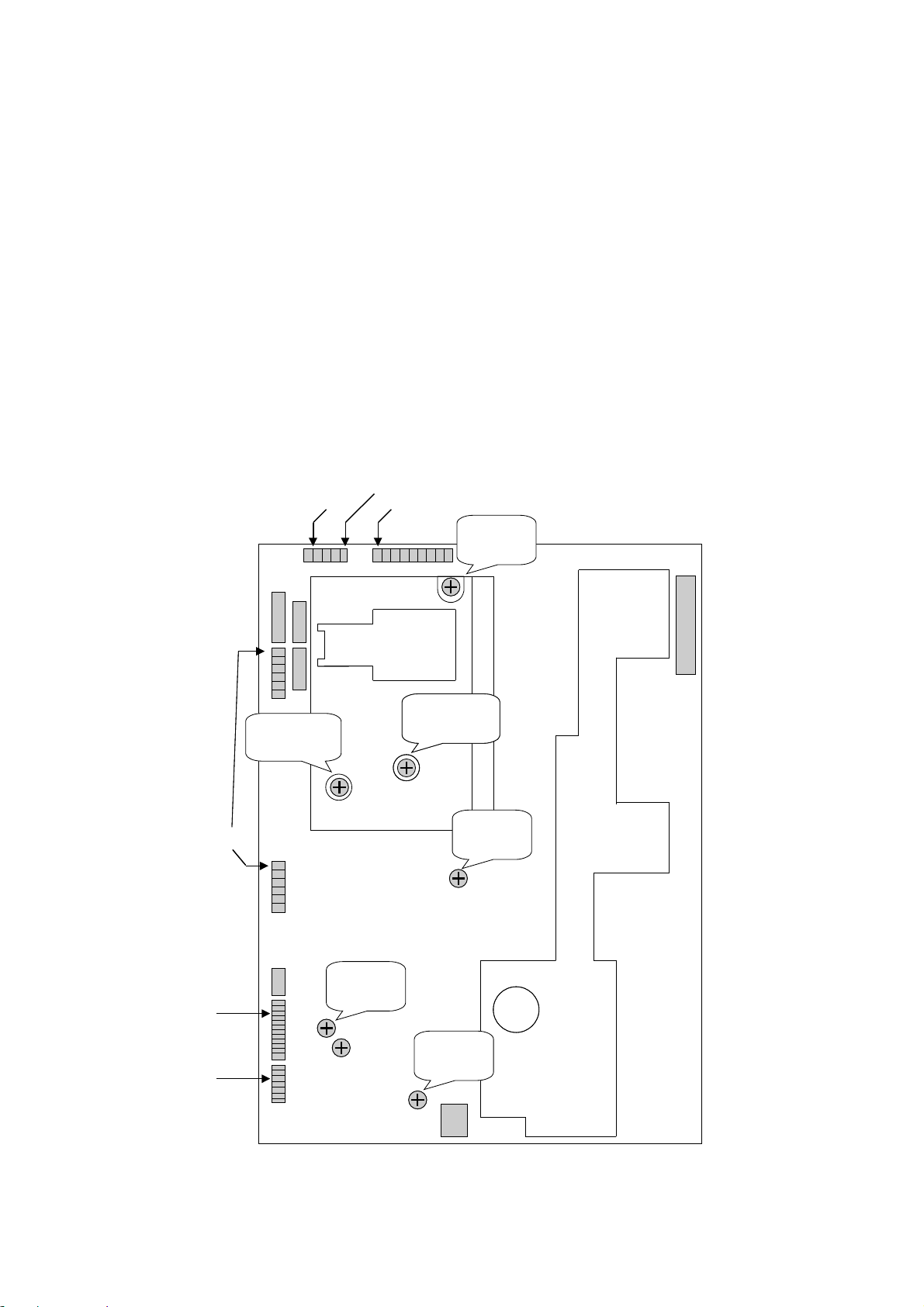
3-2. Connection Diagram for Measuring
Refer to Fig 1.
3-3. Adjustment Method
(1) Va Adjusment
¤ Connect pin 1 of CN806 or CN811 to (+) jack of D.M.M.
¤ŁAfter turning the VR351(Va CTL), voltage of D.M.M
adjustment as same as Va voltage which on label of
panel right/top.(Deviation : ±0.5V)
(2) Vs Adjustment
¤ Connect pin 1 of CN803 to (+) jack of D.M.M.
¤ŁAfter turning the VR551(Vs CTL), voltage of D.M.M
adjust as same as Vs voltage which indicated on label
of panel right/top.(Deviation : ±0.5V)
(3) V-y Adjustment
¤ Connect pin 1 of CN802 to (+) jack of D.M.M.
¤ŁAfter turning the VR751(V-y CTL), voltage of D.M.M
adjust as same as V-y voltage which indicated on label
of panel right/top.(Deviation : ±0.5V)
(4) Vsetup Adjustment
¤ Connect pin 5 of CN802 to (+) jack of D.M.M.
¤ŁAfter turning the VR651(V
SETUP CTL), voltage of D.M.M
adjust as same as Vs voltage which indicated on label
of panel right/top.(Deviation : ±0.5V)
(5) 5V Adjustment
¤ Connect pin 3 of CN809 to (+) jack of D.M.M.
¤ŁAfter turning the VR253(5V CTL), adjust the voltage of
D.M.M to 5.1V.(Deviation : ±0.05V)
(6) STBY 5V Adjustment
¤ Connect pin 3 of CN808 to (+) jack of D.M.M.
¤ŁCheck the voltage(5V) of D.M.M.
¤ØAdjust the voltage of D.M.M so that voltage of D.M.M is
5V. (Deviation : ±0.05V)
[ Refer to Typical Voltage
1. Va : 60 ~ 75V
2. Vs : 170 ~ 185V
3. -Vy : -60 ~ -90V
4. Vsetup : 210 ~ 240V
4. Adjustment of White Balance
4-1. Required Equipment
Color analyzer(CA-100 or same production)
4-2. Connection Diagram of Equipment for
Measuring
[ After stop the Micom by pressing IN-START Key on Remote
Control, insert the P1002 with automatic adjustment of
connector.
After remove connector, move the Micom by pressing ENTER
Key.
ADJUSTMENT INSTRUCTIONS
COLOR
ANALYZER
TYPE; CA-100
Window
CVBS Signal Input
High Light
85±5cd/m2
Low Light
8±3cd/m2
PDP MONITOR
MSPG-2100 or
MSTG-5200
<Fig 2> Connection Diagram of Automatic Adjustment
Page 2
- 8 -
4-3. Adjustment of White Balance
¥ Operate the Zero-calibration of the CAÑ100, then stick
sensor to PDP module surface when you adjust.
¥ For manual adjustment, it is also possible by the following
sequence.
(1) Select WHITE PATTERN of HEAT RUN mode by pressing
ADJ button on Remote Control for adjustment then operate
HEAT RUN more than 15 minute.
(2) Supply 10 step gray scale bar signal in pattern generater.
(A/V Input)
(3) To adjust Low Light, stick sensor to 9th pattern(Dark),
select the W/B by pressing ADJ button on Remote Control
for adjustment and press the VOL + button enter
Adjustment Mode.
After select the G cut and B cut, press the VOL +/- Key
and adjust it until color coordination becomes (R cut
fixation)
color coordination : X=0.270±0.003, Y=0.280±0.003
color temperature : 10,000
cK ± 500cK
(4) To adjust High Light, stick sensor to 2th pattern(White),
select the W/B by pressing ADJ button on Remote Control
for adjustment and press the VOL + button enter
Adjustment Mode.
After select the R GAIN and G GAIN, press the VOL +/Key and adjust it until color coordination becomes (B GAIN
fixation)
color coordination : X=0.270±0.003, Y=0.280±0.003
color temperature : 10,000cK ± 500cK
(5) Confirm the result of the High Light adjustment.
If the deviation of High Light occur, operate the adjustment
of Low Light and High Light again.
(6) Exit adjustment mode using Enter button.
Vs
Va CTL
- Vy CTL
VR751
Vsetup CTL
VR651
- Vy
Vsetup
Vs
- Vy CTL
VR751
Vsetup CTL
VR651
- Vy
Vsetup
Va
CN811
CN809
CN808
5V
CN806
CN802
CN803
STBY 5V
VR 351
Va CTL
VR 253
5V
VR 151
STBY 5V
Va CTL
VR 551
Vs CTL
<Fig 1>
Page 3
- 9 -
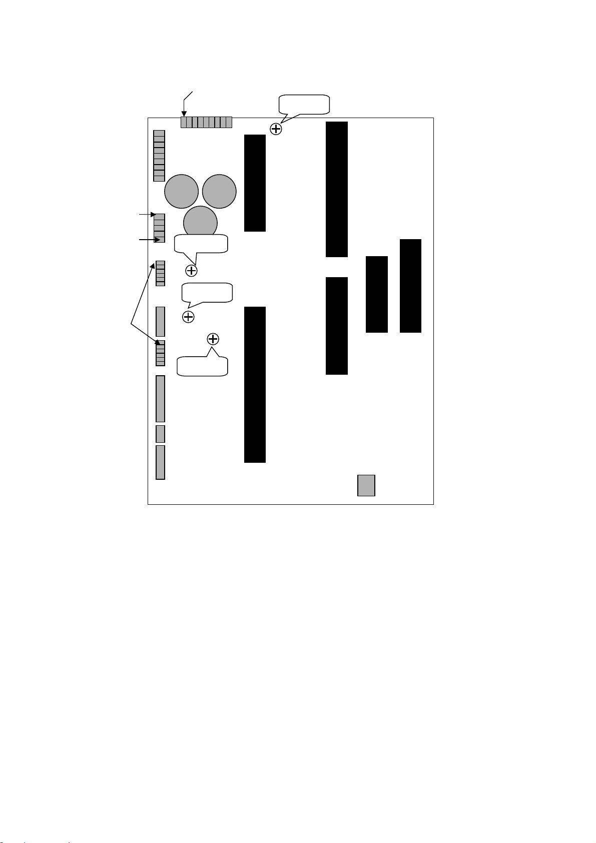
- Vy
Vsetup
Vs
Va
Vsetup ADJ
VR8104
Va ADJ
VR8105
Vs ADJ
VR8102
- Vy ADJ
VR8103
<Fig 2> Connection Diagram of POWERWEL Power Adj. for Measuring
Page 4
- 10 -
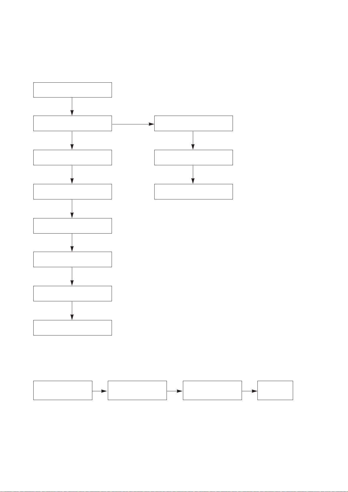
TROUBLESHOOTING
1. No Video
2. No Sound
Abnormal Picture
Input PC signal.
Normal
Abnormal
Check CXA2101
IC203
Normal
Check ADV7123
IC406
Check JAGASM
IC501
Check 74F541D
IC902~IC905
Check cable of pin 41
P902
Normal
Check FLI2220
IC404
Normal
Check FLI2200
IC403
Normal
Check VPC3230
IC201
Normal
Check Input jack & Connector.
Check connector
speaker to set.
Check MSP3401
IC601
Check LA4282
IC603
Check Input
Jack.
Page 5
- 11 -
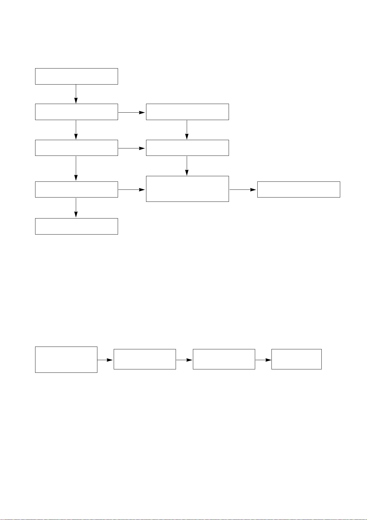
3. No Video
4. No Sound
Nothing output of image.
Check Input of AC.
(90~225V)
Normal
Abnormal
Abnormal
Abnormal
Check ST-BY LED ON
Main S/W ON.
Normal
Check LED YELLOW
Sub S/W ON.
Connect plug with the set.
Check AC Line Fuse.
Check voltage of Vs after open
with CN802, CN803, CN804.
Check short of Q603, Q703.
Abnormal
Replace Q603, Q703.
Normal
Check a connective condition
and various connector.
Check a connective
condition of sound power
cable.
Check voltage of sound
terminal.
Check Open with F8811
Fuse.
Check connection
line of speaker.
Page 6
- 12 -
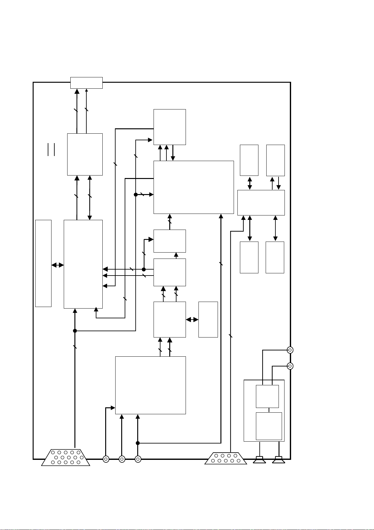
BLOCK DIAGRAM
1. VSC
MICOM
EEPROM
X2416P
AUDIO
L
R
AUDIO AMP
LA4282
(L & R)
5
RGBHV
COLOR DECODER
(VPC3230D)
DEINTERLACE
(FLI2200)
MEMORY
(4M-BYTE)
ENHANCER
(FLI2220)
COLOR CONTROL
&
VIDEO SWITCH
(CXA2101Q)
3Y,Pb,Pr(MNT)
SCALER
(JAGASM)
MEMORY
(8M-BYTE)
EPLD
(GEN. CLAMP)
Buffer
(74F574 x 4)
H
V
Clamp
2H/V
H
5H/V/CLK/
HBLK/VBLK
4
H/V/DE/CLK
5
RGBHV
3RGB
AUDIO
SWITCH
(LA7222)
2
H/V
PORT EXP
(M62320X4)
ROM
(AT29C010)
(74HCT373)
YCbCr/
YPbPr
CVBS
Y/C
41P
4
4
H/V/
FIELD/
LLC1
2H/V
DAC
(ADV7123)
5
RGBHV
16
YUV
30
RGB
RGB
30
YUV
16
24
RGB
2
Rx,Tx
Digital Line
Analog Line
H/V/DE/CLK
24
RGB
Page 7

- 13 -
2. POWER
RELAY_ON
5V_MONI
Vs_ON
AC_ON
5V (MAIN)
GND
Va
GND
Vs
GND
GND
Vsetup
GND
-Vy
GND
GND
15V
GND
12V
30V
INPUT
110~220VAC
RECTIFIER
FILTER
(FOR EMI)
RECTIFIER
AC
MONITOR
RECTIFIER
& FILTER
RECTIFIER
5V
MONITOR
MICOM
5V (ST-BY)
GND
DC/DC CONV.
REGULATOR
DRIVE &
RCC SWITCHING
O.V.P, U.V.P
DETECTOR
DRIVE
PFC
CONTROL
& DRIVE
PFC
SWITCHING
RECTIFIER
&
FILTER
FILTER
DRIVE &
FLYBACK
SWITCHING
DRIVE &
FLYBACK
SWITCHING
DRIVE &
FORWARD
SWITCHING
DRIVE &
RCC SWITCHING
Page 8

- 14 -
EXPLODED VIEW
301
303
302
200
203
201
202
205
211
204
207
208
209
206
400
540
401
550
551
530
560
570
300
212
305
520
580
Page 9

- 15 -
EXPLODED VIEW PARTS LIST
200 6348Q-E032D PDP,42Ó 16:9 852*480 FOR DND INTER
201 6871QTH023A Z Conn. TOP
202 6871QZH020A Z Sus
203 6871QTH024A Z Conn. BTM
204 6871QRH013A X Right BTM
205 6871QLH015A X Left BTM
206 6871QYH018A Y SUS
207 6871QDP026A Y DRV.LOW
208 6871QDP025A Y DRV.UP
209 6871QCH013A CTRL
211 4980V00240A SUPPORTER,VERTICAL EGI
212 4980V00240B SUPPORTER,VERTICAL EGI
300 3091V00333M CABINET ASSEMBLY,ZENITH
301 4980V00266A SUPPORTER ASSY,FILTER TOP AL MN-42PZ10
302 4980V00267A SUPPORTER ASSY,FILTER BOTTOM AL MN-42PZ1
303 4980V00268A SUPPORTER ASSY,FILTER SIDE AL MN-42PZ10
305 3790V00281C WINDOW,1142G02C MN42PZ10 ETCHING MESH
400 3809V00279H BACK COVER ASSEMBLY
401 3300V00096D PLATE,AV SEPARATORY
520 6871VMMB73A PCB ASSEMBLY,MAIN NF-01DC MN-42PZ15 VSC MAI
530 3501V00053B BOARD ASSEMBLY,EMI FILTER MURATA
540 6871VSM909A PCB ASSEMBLY,SUB NF-01DA MN-42PZ10 MNT CONT
550 6871VSM911A PCB ASSEMBLY,SUB NF-01DA MN-42PZ10 MNT POWE
551 5020V00457A BUTTON,KEY BUTTON POWER FD-36X3
560 6871VSM910A PCB ASSEMBLY,SUB NF-01DA MN-42PZ10 MNT SPK
570 3501V00052B BOARD ASSEMBLY,AC/DC CONVERTOR
580 6871VSMA90B PCB ASSEMBLY,SUB A/V NF-01DC AV PACK
No.
Part No.
Description
Page 10

REPLACEMENT PARTS LIST
LOCA. NO PART NO DESCRIPTION
Q108
Q109
Q110
Q111
Q112
Q113
Q114
Q115
Q116
Q117
Q118
Q121
Q250
Q251
Q252
Q301
Q302
Q303
Q304
Q404
Q405
Q406
Q601
Q602
Q603
D101
D102
D103
D104
D105
D250
D252
D401
D402
D601
D602
D603
D610
LD001
LD801
LD802
LD803
ZD103
ZD104
ZD105
C001
0TR387500AA
0TR387500AA
0TR387500AA
0TR387500AA
0TR387500AA
0TR387500AA
0TR387500AA
0TR387500AA
0TR387500AA
0TR387500AA
0TR387500AA
0TR104009AF
0TR150400BA
0TR150400BA
0TR150400BA
0TR387500AA
0TR387500AA
0TR150400BA
0TR387500AA
0TR150400BA
0TR150400BA
0TR150400BA
0TR150400BA
0TR150400BA
0TR150400BA
0DD226239AA
0DD226239AA
0DD226239AA
0DD226239AA
0DD226239AA
0DD226239AA
0DD184009AA
0DL233309AC
0DL233309AC
0DD184009AA
0DD184009AA
0DD184009AA
0DD226239AA
0DL200000CA
0DL233309AC
0DL233309AC
0DL233309AC
0DZRM00178A
0DZRM00178A
0DZRM00178A
0CN1040K949
CHIP 2SC3875S(ALY) KEC
CHIP 2SC3875S(ALY) KEC
CHIP 2SC3875S(ALY) KEC
CHIP 2SC3875S(ALY) KEC
CHIP 2SC3875S(ALY) KEC
CHIP 2SC3875S(ALY) KEC
CHIP 2SC3875S(ALY) KEC
CHIP 2SC3875S(ALY) KEC
CHIP 2SC3875S(ALY) KEC
CHIP 2SC3875S(ALY) KEC
CHIP 2SC3875S(ALY) KEC
CHIP KRC104S SOT-23 TP KEC - -
CHIP 2SA1504S(ASY) KEC
CHIP 2SA1504S(ASY) KEC
CHIP 2SA1504S(ASY) KEC
CHIP 2SC3875S(ALY) KEC
CHIP 2SC3875S(ALY) KEC
CHIP 2SA1504S(ASY) KEC
CHIP 2SC3875S(ALY) KEC
CHIP 2SA1504S(ASY) KEC
CHIP 2SA1504S(ASY) KEC
CHIP 2SA1504S(ASY) KEC
CHIP 2SA1504S(ASY) KEC
CHIP 2SA1504S(ASY) KEC
CHIP 2SA1504S(ASY) KEC
CHIP KDS226 SOT-23
CHIP KDS226 SOT-23
CHIP KDS226 SOT-23
CHIP KDS226 SOT-23
CHIP KDS226 SOT-23
CHIP KDS226 SOT-23
KDS184S CHIP 85V 300MA KEC TP
LED,SAM2333 TP KWANG GREEN/RED GRE
LED,SAM2333 TP KWANG GREEN/RED GRE
KDS184S CHIP 85V 300MA KEC TP
KDS184S CHIP 85V 300MA KEC TP
KDS184S CHIP 85V 300MA KEC TP
CHIP KDS226 SOT-23
LED,SAM5670(DL-2LRG) BK Y-GREEN -
LED,SAM2333 TP KWANG GREEN/RED GRE
LED,SAM2333 TP KWANG GREEN/RED GRE
LED,SAM2333 TP KWANG GREEN/RED GRE
ZENERS,UDZS TE-17 5.1B
ZENERS,UDZS TE-17 5.1B
ZENERS,UDZS TE-17 5.1B
0.1M 50V Z F TA52
LOCA. NO PART NO DESCRIPTION
IC102
IC104
IC201
IC202
IC203
IC204
IC301
IC402
IC403
IC404
IC406
IC501
IC502
IC503
IC601
IC602
IC603
IC605
IC701
IC702
IC703
IC704
IC706
IC707
IC708
IC709
IC710
IC802
IC803
IC804
IC806
IC807
IC902
IC903
IC904
IC905
IC1101
Q001
Q002
Q101
Q102
Q103
Q104
Q105
Q106
Q107
0IDS232000A
0IFA741230A
0IIT323000C
0IKE704200J
0ISO210100B
0ISH092100A
0IMCRFA012A
0ISS464323A
0IMCRG2001A
0IMCRG2002A
0IMCRAD001A
0IMCRG2004A
0ISS464323A
0ISS464323A
0IMCRMN002A
0IKE704200J
0ISA428200A
0IKE780800A
0IMI623200B
0IMI623200B
0IMI623200B
0IAL241610A
0IMCRNS001A
0IPH740400G
0IPH806520A
0IZZVA0051A
0IPH743730E
0IMCRRH001A
0ILT176425A
0IMCRRH001A
0IMCRRH001A
0ILT176425A
0IPH745410A
0IPH745410A
0IPH745410A
0IPH745410A
0IMCRAT003A
0TR319809AA
0TR319809AA
0TR387500AA
0TR387500AA
0TR387500AA
0TR387500AA
0TR387500AA
0TR387500AA
0TR387500AA
DS232AS 16P,SOP TP RS-232 DRIV
DM74LS123MX 16SOP TP DUAL RETR
VPC3230D-QA-B3 80P PQFP BK COM
KIA7042AF SOT-89 TP 4.2V VOLTA
CXA2101AQ 80P,QFP BK VIDEO SIG
PQ09RF21 4P 9V S/W REGULATOR -
DM74LS157MX FAIRCHILD 16P SOIC
K4S643232E(C)-TC/L60(70) (KM43
FLI2200 SAGE 176P,QFP TRAY VID
FLI2220 SAGE 160P,QFP TRAY DIG
ADV7123KSTC140 ANALOG DEVICE 4
JAGASM SAGE 352BALL TRAY HIGHL
K4S643232E(C)-TC/L60(70) (KM43
K4S643232E(C)-TC/L60(70) (KM43
MSP3400G QA B6 MICRONAS 80 QFP
KIA7042AF SOT-89 TP 4.2V VOLTA
LA4282 12S 2CHX10W AUDIO AMP
KIA7808PI 3P(TO-220IS) 1A,8V -
M62320FP,I/O EXPANDER 16P SOP
M62320FP,I/O EXPANDER 16P SOP
M62320FP,I/O EXPANDER 16P SOP
AT24C16N-10SI 8P SOIC ST EEPRO
LM810 NATIONAL SEMICONDUCTOR 3
74HC04D HEX INVERTER 14P,SOP T
80C652 40 PLCC ST 8-BIT MICROC
AT27C020 32PIN DIP ST MICOM MN
74HCT373D 20SOP R/TP ADDRESS L
BA033FP ROHM 3P-SOP,TO252-3 R/
LT1764EQ-2.5 5PIN Q PACKAGE R
BA033FP ROHM 3P-SOP,TO252-3 R/
BA033FP ROHM 3P-SOP,TO252-3 R/
LT1764EQ-2.5 5PIN Q PACKAGE R
74F541 20P SOT BK BUFFER MXIC
74F541 20P SOT BK BUFFER MXIC
74F541 20P SOT BK BUFFER MXIC
74F541 20P SOT BK BUFFER MXIC
EPM7064STC44-100 ALTERA 44P,QF
KTC3198 TP KEC - - -Y (KTC1815
KTC3198 TP KEC - - -Y (KTC1815
CHIP 2SC3875S(ALY) KEC
CHIP 2SC3875S(ALY) KEC
CHIP 2SC3875S(ALY) KEC
CHIP 2SC3875S(ALY) KEC
CHIP 2SC3875S(ALY) KEC
CHIP 2SC3875S(ALY) KEC
CHIP 2SC3875S(ALY) KEC
IC
TRANSISTOR
- 16 -
RUN DATE : 2002.3.19
DIODE
CAPACITOR
For Capacitor & Resistors, the
charactors at 2nd and 3rd digit
in the P/No. means as follows;
CC, CX, CK, CN : Ceramic
CQ : Polyestor
CE : Electrolytic
RD : Carbon Film
RS : Metal Oxide Film
RN : Metal Film
RF : Fusible
Page 11

- 17 -
LOCA. NO PART NO DESCRIPTION
C002
C109
C112
C115
C118
C125
C128
C129
C130
C135
C136
C139
C166
C171
C173
C202
C203
C205
C212
C214
C216
C217
C218
C219
C220
C221
C224
C227
C230
C233
C246
C255
C267
C274
C275
C278
C288
C290
C293
C300
C310
C320
C373
C402
C405
C408
C411
C414
C439
C441
C442
C471
C476
0CE476DD618
0CE476SF6DC
0CE476SF6DC
0CE476SF6DC
0CE476SF6DC
0CE106SF6DC
0CE476SF6DC
0CE476SF6DC
0CE476SF6DC
0CE476SF6DC
0CE476SF6DC
0CE476SF6DC
0CE476SF6DC
0CE107SF6DC
0CE107SF6DC
0CE106SF6DC
0CE107SF6DC
0CK224DF56A
0CK224DF56A
0CE106SF6DC
0CK224DF56A
0CK224DF56A
0CK224DF56A
0CK224DF56A
0CK224DF56A
0CK224DF56A
0CE476SF6DC
0CE476SF6DC
0CK224DF56A
0CE476SF6DC
0CE106SF6DC
0CE476SF6DC
0CE105SK6DC
0CE107SF6DC
0CE107SF6DC
0CE476SF6DC
0CE106SF6DC
0CE106SF6DC
0CE476SF6DC
0CE107SF6DC
0CE476SF6DC
0CE476SF6DC
0CE1051K636
0CE476SF6DC
0CE476SF6DC
0CE476SF6DC
0CE476SF6DC
0CE476SF6DC
0CE476SF6DC
0CE476SF6DC
0CE476SF6DC
0CE106SF6DC
0CE106SF6DC
47UF STD 10V 20% FL TP 5
47UF MVG 16V M SMD R/TP
47UF MVG 16V M SMD R/TP
47UF MVG 16V M SMD R/TP
47UF MVG 16V M SMD R/TP
10UF MVG 16V 20% R/TP(SMD) SMD
47UF MVG 16V M SMD R/TP
47UF MVG 16V M SMD R/TP
47UF MVG 16V M SMD R/TP
47UF MVG 16V M SMD R/TP
47UF MVG 16V M SMD R/TP
47UF MVG 16V M SMD R/TP
47UF MVG 16V M SMD R/TP
100UF MVG 16V M SMD R/TP
100UF MVG 16V M SMD R/TP
10UF MVG 16V 20% R/TP(SMD) SMD
100UF MVG 16V M SMD R/TP
220000PF 2012 16V 10% R/TP X7R
220000PF 2012 16V 10% R/TP X7R
10UF MVG 16V 20% R/TP(SMD) SMD
220000PF 2012 16V 10% R/TP X7R
220000PF 2012 16V 10% R/TP X7R
220000PF 2012 16V 10% R/TP X7R
220000PF 2012 16V 10% R/TP X7R
220000PF 2012 16V 10% R/TP X7R
220000PF 2012 16V 10% R/TP X7R
47UF MVG 16V M SMD R/TP
47UF MVG 16V M SMD R/TP
220000PF 2012 16V 10% R/TP X7R
47UF MVG 16V M SMD R/TP
10UF MVG 16V 20% R/TP(SMD) SMD
47UF MVG 16V M SMD R/TP
1UF MVG 50V M SMD R/TP
100UF MVG 16V M SMD R/TP
100UF MVG 16V M SMD R/TP
47UF MVG 16V M SMD R/TP
10UF MVG 16V 20% R/TP(SMD) SMD
10UF MVG 16V 20% R/TP(SMD) SMD
47UF MVG 16V M SMD R/TP
100UF MVG 16V M SMD R/TP
47UF MVG 16V M SMD R/TP
47UF MVG 16V M SMD R/TP
1UF SM,SA 50V 20% FM5 BP(D) TP
47UF MVG 16V M SMD R/TP
47UF MVG 16V M SMD R/TP
47UF MVG 16V M SMD R/TP
47UF MVG 16V M SMD R/TP
47UF MVG 16V M SMD R/TP
47UF MVG 16V M SMD R/TP
47UF MVG 16V M SMD R/TP
47UF MVG 16V M SMD R/TP
10UF MVG 16V 20% R/TP(SMD) SMD
10UF MVG 16V 20% R/TP(SMD) SMD
LOCA. NO PART NO DESCRIPTION
C479
C487
C503
C506
C509
C512
C515
C518
C521
C524
C554
C601
C602
C604
C609
C610
C611
C612
C614
C616
C626
C630
C631
C640
C641
C643
C644
C647
C651
C652
C653
C654
C655
C656
C658
C659
C660
C661
C662
C671
C672
C673
C674
C675
C676
C699
C709
C711
C715
C717
C718
C720
C802
0CE476SF6DC
0CE106SF6DC
0CE106SF6DC
0CE106SF6DC
0CE106SF6DC
0CE106SF6DC
0CE106SF6DC
0CE106SF6DC
0CE106SF6DC
0CE106SF6DC
0CE106SF6DC
0CE476SF6DC
0CE476SF6DC
0CE106SF6DC
0CE107SF6DC
0CE106SF6DC
0CE106SF6DC
0CE335SK6DC
0CE106SF6DC
0CE106SF6DC
0CE107SF6DC
0CE477DK618
0CE477DK618
0CE474SK6DC
0CE474SK6DC
0CE474SK6DC
0CE474SK6DC
0CE107SF6DC
0CE227VF6DC
0CE105SK6DC
0CE107DH618
0CE106SF6DC
0CE107DH618
0CE107DH618
0CQ6821N509
0CE106SF6DC
0CQ6821N509
0CQ1041N509
0CQ1041N509
0CE477DK618
0CE477DK618
0CE477DK618
0CE477DK618
181-120K
181-120K
0CE227VF6DC
0CE476SF6DC
0CE106SF6DC
0CE106SF6DC
0CE106SF6DC
0CE106SF6DC
0CE105SK6DC
0CE227VF6DC
47UF MVG 16V M SMD R/TP
10UF MVG 16V 20% R/TP(SMD) SMD
10UF MVG 16V 20% R/TP(SMD) SMD
10UF MVG 16V 20% R/TP(SMD) SMD
10UF MVG 16V 20% R/TP(SMD) SMD
10UF MVG 16V 20% R/TP(SMD) SMD
10UF MVG 16V 20% R/TP(SMD) SMD
10UF MVG 16V 20% R/TP(SMD) SMD
10UF MVG 16V 20% R/TP(SMD) SMD
10UF MVG 16V 20% R/TP(SMD) SMD
10UF MVG 16V 20% R/TP(SMD) SMD
47UF MVG 16V M SMD R/TP
47UF MVG 16V M SMD R/TP
10UF MVG 16V 20% R/TP(SMD) SMD
100UF MVG 16V M SMD R/TP
10UF MVG 16V 20% R/TP(SMD) SMD
10UF MVG 16V 20% R/TP(SMD) SMD
3.3UF MVG 50V 20% SMD R/TP
10UF MVG 16V 20% R/TP(SMD) SMD
10UF MVG 16V 20% R/TP(SMD) SMD
100UF MVG 16V M SMD R/TP
470UF STD 50V 20% FL TP 5
470UF STD 50V 20% FL TP 5
0.47UF MVG 50V M SMD R/TP
0.47UF MVG 50V M SMD R/TP
0.47UF MVG 50V M SMD R/TP
0.47UF MVG 50V M SMD R/TP
100UF MVG 16V M SMD R/TP
220UF MV 16V 20% R/TP(SMD) SMD
1UF MVG 50V M SMD R/TP
100UF STD 25V M FL TP5
10UF MVG 16V 20% R/TP(SMD) SMD
100UF STD 25V M FL TP5
100UF STD 25V M FL TP5
0.0068U 100V K POLY TP
10UF MVG 16V 20% R/TP(SMD) SMD
0.0068U 100V K POLY TP
0.1U 100V K POLY TP
0.1U 100V K POLY TP
470UF STD 50V 20% FL TP 5
470UF STD 50V 20% FL TP 5
470UF STD 50V 20% FL TP 5
470UF STD 50V 20% FL TP 5
2200PF 4KV M E FMTW LEAD 4.5
2200PF 4KV M E FMTW LEAD 4.5
220UF MV 16V 20% R/TP(SMD) SMD
47UF MVG 16V M SMD R/TP
10UF MVG 16V 20% R/TP(SMD) SMD
10UF MVG 16V 20% R/TP(SMD) SMD
10UF MVG 16V 20% R/TP(SMD) SMD
10UF MVG 16V 20% R/TP(SMD) SMD
1UF MVG 50V M SMD R/TP
220UF MV 16V 20% R/TP(SMD) SMD
For Capacitor & Resistors, the
charactors at 2nd and 3rd digit
in the P/No. means as follows;
CC, CX, CK, CN : Ceramic
CQ : Polyestor
CE : Electrolytic
RD : Carbon Film
RS : Metal Oxide Film
RN : Metal Film
RF : Fusible
Page 12

- 18 -
LOCA. NO PART NO DESCRIPTION
C806
C810
C814
C815
C818
C821
C824
C825
C826
C828
C829
C832
C834
C843
C844
C847
C849
C850
C855
C856
C861
C863
C864
C869
C871
C874
C876
C877
C1103
C1106
C1113
C1720
JP1
P101
P102
P103
P201B
L001
L801
L804
L808
L813
P007B
P101
P102
P1001
0CE227VF6DC
0CE227VF6DC
0CE476SF6DC
0CE476SF6DC
0CE227VF6DC
0CE107SF6DC
0CE227VF6DC
0CE106SF6DC
0CE476SF6DC
0CE106SF6DC
0CE106SF6DC
0CE476SF6DC
0CE106SF6DC
0CE227VF6DC
0CE227VF6DC
0CE227VF6DC
0CE476SF6DC
0CE476SF6DC
0CE476SF6DC
0CE476SF6DC
0CE106SF6DC
0CE477BF618
0CE477BF618
0CE108DF618
0CE107SF6DC
0CE227VF6DC
0CE106SF6DC
0CE106SF6DC
0CE106SF6DC
0CE107SF6DC
0CE476SF6DC
0CE106SF6DC
6612VLH002A
6612J00010B
6612J00010A
380-363K
6612VJH018A
0LA0102K119
6140VB0004B
6140VB0004B
6140VB0004B
6140VB0004B
387-A04H
6630VGA001C
6630GL00181
6630VGA004B
220UF MV 16V 20% R/TP(SMD) SMD
220UF MV 16V 20% R/TP(SMD) SMD
47UF MVG 16V M SMD R/TP
47UF MVG 16V M SMD R/TP
220UF MV 16V 20% R/TP(SMD) SMD
100UF MVG 16V M SMD R/TP
220UF MV 16V 20% R/TP(SMD) SMD
10UF MVG 16V 20% R/TP(SMD) SMD
47UF MVG 16V M SMD R/TP
10UF MVG 16V 20% R/TP(SMD) SMD
10UF MVG 16V 20% R/TP(SMD) SMD
47UF MVG 16V M SMD R/TP
10UF MVG 16V 20% R/TP(SMD) SMD
220UF MV 16V 20% R/TP(SMD) SMD
220UF MV 16V 20% R/TP(SMD) SMD
220UF MV 16V 20% R/TP(SMD) SMD
47UF MVG 16V M SMD R/TP
47UF MVG 16V M SMD R/TP
47UF MVG 16V M SMD R/TP
47UF MVG 16V M SMD R/TP
10UF MVG 16V 20% R/TP(SMD) SMD
470UF KME 16V M FL TP5
470UF KME 16V M FL TP5
1000UF STD 16V M FL TP5
100UF MVG 16V M SMD R/TP
220UF MV 16V 20% R/TP(SMD) SMD
10UF MVG 16V 20% R/TP(SMD) SMD
10UF MVG 16V 20% R/TP(SMD) SMD
10UF MVG 16V 20% R/TP(SMD) SMD
100UF MVG 16V M SMD R/TP
47UF MVG 16V M SMD R/TP
10UF MVG 16V 20% R/TP(SMD) SMD
JACK,RCA SP026B 4P RD/BK/BK/R
JACK,RCA PPJ128A-2 A/V 3P WITH
JACK,RCA PPJ128A-1 A/V 2P MONO
JACK,DIN PJ6046G H=8.0 W/O S/W
JACK,RCA PJ6058C-A A/V 2P MON
INDUCTOR,10UH K
COIL,CHOKE 26UH 1UEWPHY 22.5TURN
COIL,CHOKE 26UH 1UEWPHY 22.5TURN
COIL,CHOKE 26UH 1UEWPHY 22.5TURN
COIL,CHOKE 26UH 1UEWPHY 22.5TURN
CONNECTOR ASSEMBLY,4P (L=450)
CONNECTOR,D-SUB 15PIN 2.29MM
CONNECTOR,D-SUB 36P 2.
CONNECTOR,D-SUB 9P 2.77MM
LOCA. NO PART NO DESCRIPTION
AR201
AR202
AR203
AR204
AR401
AR402
AR403
AR404
AR405
AR406
AR407
AR408
AR409
AR410
AR411
AR412
AR413
AR414
AR415
AR416
AR417
AR418
AR419
AR420
AR421
AR422
AR423
AR424
AR425
AR426
AR427
AR428
AR503
AR504
AR507
AR508
AR511
AR512
AR513
AR514
AR515
AR516
AR517
AR518
AR519
AR520
AR521
AR522
AR523
AR524
AR525
0RRZVTA001A
0RRZVTA001A
0RRZVTA001A
0RRZVTA001A
0RRZVTA001A
0RRZVTA001A
0RRZVTA001A
0RRZVTA001A
0RRZVTA001A
0RRZVTA001A
0RRZVTA001A
0RRZVTA001A
0RRZVTA001A
0RRZVTA001A
0RRZVTA001A
0RRZVTA001A
0RRZVTA001A
0RRZVTA001A
0RRZVTA001A
0RRZVTA001A
0RRZVTA001A
0RRZVTA001A
0RRZVTA001A
0RRZVTA001A
0RRZVTA001A
0RRZVTA001A
0RRZVTA001A
0RRZVTA001A
0RRZVTA001A
0RRZVTA001A
0RRZVTA001A
0RRZVTA001A
0RRZVTA001A
0RRZVTA001A
0RRZVTA001A
0RRZVTA001A
0RRZVTA001A
0RRZVTA001A
0RRZVTA001A
0RRZVTA001A
0RRZVTA001A
0RRZVTA001A
0RRZVTA001A
0RRZVTA001A
0RRZVTA001A
0RRZVTA001A
0RRZVTA001A
0RRZVTA001A
0RRZVTA001A
0RRZVTA001A
0RRZVTA001A
MNR-14-E0A-J-101 R OHM 100 OH
MNR-14-E0A-J-101 R OHM 100 OH
MNR-14-E0A-J-101 R OHM 100 OH
MNR-14-E0A-J-101 R OHM 100 OH
MNR-14-E0A-J-101 R OHM 100 OH
MNR-14-E0A-J-101 R OHM 100 OH
MNR-14-E0A-J-101 R OHM 100 OH
MNR-14-E0A-J-101 R OHM 100 OH
MNR-14-E0A-J-101 R OHM 100 OH
MNR-14-E0A-J-101 R OHM 100 OH
MNR-14-E0A-J-101 R OHM 100 OH
MNR-14-E0A-J-101 R OHM 100 OH
MNR-14-E0A-J-101 R OHM 100 OH
MNR-14-E0A-J-101 R OHM 100 OH
MNR-14-E0A-J-101 R OHM 100 OH
MNR-14-E0A-J-101 R OHM 100 OH
MNR-14-E0A-J-101 R OHM 100 OH
MNR-14-E0A-J-101 R OHM 100 OH
MNR-14-E0A-J-101 R OHM 100 OH
MNR-14-E0A-J-101 R OHM 100 OH
MNR-14-E0A-J-101 R OHM 100 OH
MNR-14-E0A-J-101 R OHM 100 OH
MNR-14-E0A-J-101 R OHM 100 OH
MNR-14-E0A-J-101 R OHM 100 OH
MNR-14-E0A-J-101 R OHM 100 OH
MNR-14-E0A-J-101 R OHM 100 OH
MNR-14-E0A-J-101 R OHM 100 OH
MNR-14-E0A-J-101 R OHM 100 OH
MNR-14-E0A-J-101 R OHM 100 OH
MNR-14-E0A-J-101 R OHM 100 OH
MNR-14-E0A-J-101 R OHM 100 OH
MNR-14-E0A-J-101 R OHM 100 OH
MNR-14-E0A-J-101 R OHM 100 OH
MNR-14-E0A-J-101 R OHM 100 OH
MNR-14-E0A-J-101 R OHM 100 OH
MNR-14-E0A-J-101 R OHM 100 OH
MNR-14-E0A-J-101 R OHM 100 OH
MNR-14-E0A-J-101 R OHM 100 OH
MNR-14-E0A-J-101 R OHM 100 OH
MNR-14-E0A-J-101 R OHM 100 OH
MNR-14-E0A-J-101 R OHM 100 OH
MNR-14-E0A-J-101 R OHM 100 OH
MNR-14-E0A-J-101 R OHM 100 OH
MNR-14-E0A-J-101 R OHM 100 OH
MNR-14-E0A-J-101 R OHM 100 OH
MNR-14-E0A-J-101 R OHM 100 OH
MNR-14-E0A-J-101 R OHM 100 OH
MNR-14-E0A-J-101 R OHM 100 OH
MNR-14-E0A-J-101 R OHM 100 OH
MNR-14-E0A-J-101 R OHM 100 OH
MNR-14-E0A-J-101 R OHM 100 OH
JACK
COIL
CONNECTOR
RESISTOR
For Capacitor & Resistors, the
charactors at 2nd and 3rd digit
in the P/No. means as follows;
CC, CX, CK, CN : Ceramic
CQ : Polyestor
CE : Electrolytic
RD : Carbon Film
RS : Metal Oxide Film
RN : Metal Film
RF : Fusible
Page 13

- 19 -
LOCA. NO PART NO DESCRIPTION
AR526
AR527
AR528
AR529
AR530
AR531
AR532
AR533
AR534
AR535
AR701
AR702
AR703
AR704
AR705
AR706
R006
R007
R623
R624
R627
R628
R655
R656
SW001
SW002
SW003
SW004
SW800
F601
F602
L102
L104
L105
L106
L201
L202
L212
L250
L251
L252
L253
L320
L401
L402
L403
L404
L405
L407
0RRZVTA001A
0RRZVTA001A
0RRZVTA001A
0RRZVTA001A
0RRZVTA001A
0RRZVTA001A
0RRZVTA001A
0RRZVTA001A
0RRZVTA001A
0RRZVTA001A
0RRZVTA001A
0RRZVTA001A
0RRZVTA001A
0RRZVTA001A
0RRZVTA001A
0RRZVTA001A
0RD3300F609
0RD3300F609
0RS0221H609
0RS0221H609
0RS2701K607
0RS2701K607
0RD4700H609
0RD4700H609
140-315A
140-315A
140-315A
140-315A
6600VM2006A
6200VJS001A
6200VJS001A
6210VC0006A
6210VC0006A
6210VC0006A
6210VC0006A
6210VC0006A
6210VC0006A
6210VC0006A
6210VC0006A
6210VC0006A
6210VC0006A
6210VC0006A
6210VC0006A
6210VC0006A
6210VC0006A
6210VC0006A
6210VC0006A
6210VC0006A
6210VC0006A
MNR-14-E0A-J-101 R OHM 100 OH
MNR-14-E0A-J-101 R OHM 100 OH
MNR-14-E0A-J-101 R OHM 100 OH
MNR-14-E0A-J-101 R OHM 100 OH
MNR-14-E0A-J-101 R OHM 100 OH
MNR-14-E0A-J-101 R OHM 100 OH
MNR-14-E0A-J-101 R OHM 100 OH
MNR-14-E0A-J-101 R OHM 100 OH
MNR-14-E0A-J-101 R OHM 100 OH
MNR-14-E0A-J-101 R OHM 100 OH
MNR-14-E0A-J-101 R OHM 100 OH
MNR-14-E0A-J-101 R OHM 100 OH
MNR-14-E0A-J-101 R OHM 100 OH
MNR-14-E0A-J-101 R OHM 100 OH
MNR-14-E0A-J-101 R OHM 100 OH
MNR-14-E0A-J-101 R OHM 100 OH
330 OHM 1/6 W 5.00% TA52
330 OHM 1/6 W 5.00% TA52
2.2 OHM 1/2 W 5.00% TA52
2.2 OHM 1/2 W 5.00% TA52
2.7K OHM 2 W 5.00% TA62
2.7K OHM 2 W 5.00% TA62
470 OHM 1/2 W 5.00% TA52
470 OHM 1/2 W 5.00% TA52
SWITCH,TACT SKHV17910B NON 12V
SWITCH,TACT SKHV17910B NON 12V
SWITCH,TACT SKHV17910B NON 12V
SWITCH,TACT SKHV17910B NON 12V
SWITCH,PUSH SDDF3PATP011
FILTER,EMC ZJY51R5-4P TDK DC 50VOLT
FILTER,EMC ZJY51R5-4P TDK DC 50VOLT
FILTER,EMC FBMH3216 HM501NT
FILTER,EMC FBMH3216 HM501NT
FILTER,EMC FBMH3216 HM501NT
FILTER,EMC FBMH3216 HM501NT
FILTER,EMC FBMH3216 HM501NT
FILTER,EMC FBMH3216 HM501NT
FILTER,EMC FBMH3216 HM501NT
FILTER,EMC FBMH3216 HM501NT
FILTER,EMC FBMH3216 HM501NT
FILTER,EMC FBMH3216 HM501NT
FILTER,EMC FBMH3216 HM501NT
FILTER,EMC FBMH3216 HM501NT
FILTER,EMC FBMH3216 HM501NT
FILTER,EMC FBMH3216 HM501NT
FILTER,EMC FBMH3216 HM501NT
FILTER,EMC FBMH3216 HM501NT
FILTER,EMC FBMH3216 HM501NT
FILTER,EMC FBMH3216 HM501NT
LOCA. NO PART NO DESCRIPTION
L408
L409
L411
L412
L501
L502
L503
L504
L505
L506
L507
L508
L509
L601
L602
L603
L604
L605
L606
L607
L608
L609
L620
L701
L802
L803
L806
L809
L810
L812
L1101
L1102
L1720
R133
R134
X201
X601
X701
PA001
X1101
A1
A2
A3
A4
6210VC0006A
6210VC0006A
6210VC0006A
6210VC0006A
6210VC0006A
6210VC0006A
6210VC0006A
6210VC0006A
6210VC0006A
6210VC0006A
6210VC0006A
6210VC0006A
6210VC0006A
150-F09A
6210VC0006A
6210VC0006A
6210VC0006A
6210VC0006A
6200JB8007L
6200JB8007L
6210VC0006A
6210VC0006A
6210VC0006A
6210VC0006A
6210VC0006A
6210VC0006A
6210VC0006A
6210VC0006A
6210VC0006A
6210VC0006A
6210VC0006A
6210VC0006A
6210VC0006A
6210VC0005A
6210VC0005A
6202VDB007B
156-A02M
6202VDT002B
6726VH0001A
6204V00001K
3828VA0296L
6710V00042S
6410VUH005A
6866VA9001B
FILTER,EMC FBMH3216 HM501NT
FILTER,EMC FBMH3216 HM501NT
FILTER,EMC FBMH3216 HM501NT
FILTER,EMC FBMH3216 HM501NT
FILTER,EMC FBMH3216 HM501NT
FILTER,EMC FBMH3216 HM501NT
FILTER,EMC FBMH3216 HM501NT
FILTER,EMC FBMH3216 HM501NT
FILTER,EMC FBMH3216 HM501NT
FILTER,EMC FBMH3216 HM501NT
FILTER,EMC FBMH3216 HM501NT
FILTER,EMC FBMH3216 HM501NT
FILTER,EMC FBMH3216 HM501NT
FILTER,EMC SQE2222 7-14MH 0.
FILTER,EMC FBMH3216 HM501NT
FILTER,EMC FBMH3216 HM501NT
FILTER,EMC FBMH3216 HM501NT
FILTER,EMC FBMH3216 HM501NT
FILTER,EMC HH2012 1M221JT
FILTER,EMC HH2012 1M221JT
FILTER,EMC FBMH3216 HM501NT
FILTER,EMC FBMH3216 HM501NT
FILTER,EMC FBMH3216 HM501NT
FILTER,EMC FBMH3216 HM501NT
FILTER,EMC FBMH3216 HM501NT
FILTER,EMC FBMH3216 HM501NT
FILTER,EMC FBMH3216 HM501NT
FILTER,EMC FBMH3216 HM501NT
FILTER,EMC FBMH3216 HM501NT
FILTER,EMC FBMH3216 HM501NT
FILTER,EMC FBMH3216 HM501NT
FILTER,EMC FBMH3216 HM501NT
FILTER,EMC FBMH3216 HM501NT
FILTER,EMC BK2125 HS 750
FILTER,EMC BK2125 HS 750
RESONATOR,CRYSTAL HC49U 20.250MHZ 3
RESONATOR,CRYSTAL HC49U 18.432MHZ 30P
RESONATOR,CRYSTAL SX-1SMD 14.318MHZ
REMOTE CONTROLLER RECEIVER,38KHZ
OSCILLATOR,SCO-0650-27.0M SUNNY RADIAL 27
MANUAL,OWNERS NF01DC MU-42PZ11A/15A ZENITH
REMOTE CONTROLLER,NEC MONITOR ONLY
POWER CORD,PS204 125V/13A VOLEX UL/CSA 2
CONNECTOR,D-SUB 2990-9C UL 1161 AWG 26
FILTER & CRYSTAL
SWITCH
For Capacitor & Resistors, the
charactors at 2nd and 3rd digit
in the P/No. means as follows;
CC, CX, CK, CN : Ceramic
CQ : Polyestor
CE : Electrolytic
RD : Carbon Film
RS : Metal Oxide Film
RN : Metal Film
RF : Fusible
MISCELLANEOUS
ACCESSORIES
Page 14

Page 15

Page 16

Page 17
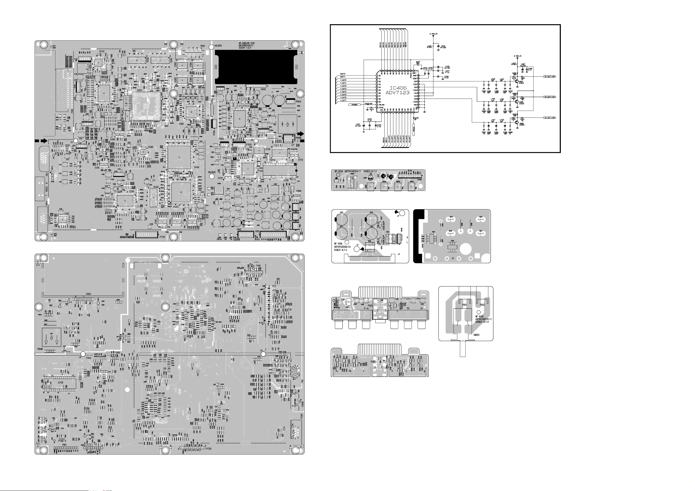
PRINTED CIRCUIT BOARD
MAIN(TOP)
MAIN(BOTTOM)
POWER S/W
CONTROL
SPK(TOP) SPK(BOTTOM)
A/V PACK (TOP)
A/V PACK (BOTTOM)
 Loading...