

Page 1
SERVICE MANUAL
Model Series:
Product Type: Projection/Directview CTV
Chassis: GM
Manual Series: CM-150 and PV-150
Manual Part #: 923-3364R1
Model Line: A
Product Year: 1998
REVISED EDITION
This revised edition includes the original GM manual
(923-03364) and the first addendum (923-03419).
A50M84D
A50M84W
A50M84W1
A50M84W5
A50M84W9
A50M91D
A50M91W
A50M91W1
A50M91W5
A50M91W9
A56M91D
A56M91W
A56M91W1
A56M91W5
A56M91W9
A60M91D
A60M91W
A60M91W1
A60M91W5
A60M91W9
IQA32M46W
IQA32M46W4
IQA32M46W7
IQA32M46W74
IQA36M46D
IQA36M46W
IQA36M46W4
IQA56M98D
IQA56M98W
IQA56M98W1
IQA56M98W5
IQA56M98W9
IQA60M98D
IQA60M98W
IQA60M98W1
IQA60M98W5
IQA60M98W9
RA46M84D
RA46M84D1
RA46M84D9
RA46M84W
RA46M84W9
RA50M84D1
RA50M84D9
RA50M84W
RA50M84W1
RA50M84W5
RA50M84W9
RA56M91D
RA56M91D9
Printed in U.S.A.
ZEN REV2 600
CONTENTS
General Info/Remotes .................................... 1
Service Menus ............................................... 2
Troublshooting/Adjustments .......................... 3
Model Parts List ............................................ 4
Mechanical Drawings ...................................... 5
Schematics and PCB Layouts ........................... 6
Published by Technical Publications
Zenith Electronics Corporation
201 James Record Road - Huntsville, Alabama 35824-1513
ÓCopyright February 1999 by Zenith Electronics Corporation
Revised Edition August 1999
Page 2
PRODUCT SAFETY SERVICING GUIDELINES FOR AUDIO-VIDEO PRODUCTS
IMPORTANT SAFETY NOTICE
This manual was prepared for use only by properly trained audio-visual service
technicians.
When servicing this product, under no circumstances should the original
design be modified or altered without permission from Zenith Electronics
Corporation. All components should be replaced only with types identical to
those in the original circuit and their physical location, wiring and lead dress
must conform to original layout upon completion of repairs.
Special components are also used to prevent x-radiation, shock and fire hazard.
These components are indicated by the letter “x” included in their component
designators and are required to maintain safe performance. No deviations are
allowed without prior approval by Zenith Electronics Corporation.
Circuit diagrams may occasionally differ from the actual circuit used. This way,
implementation of the latest safety and performance improvement changes into
the set is not delayed until the new service literature is printed.
CAUTION: Do not attempt to modify this product in any way. Never perform
customized installations without manufacturer’s approval. Unauthorized
modifications will not only void the warranty, but may lead to property damage
or user injury.
Service work should be performed only after you are thoroughly familiar with
these safety checks and servicing guidelines.
GRAPHIC SYMBOLS
The exclamation point within an equilateral triangle is intended
to alert the service personnel to important safety information in
the service literature.
The lightning flash with arrowhead symbol within an equilateral
triangle is intended to alert the service personnel to the presence
of noninsulated “dangerous voltage” that may be of sufficient
magnitude to constitute a risk of electric shock.
The pictorial representation of a fuse and its rating within an
equilateral triangle is intended to convey to the service personnel
the following fuse replacement caution notice:
CAUTION: FOR CONTINUED PROTECTION AGAINST RISK OF FIRE,
REPLACE ALL FUSES WITH THE SAME TYPE AND RATING AS MARKED
NEAR EACH FUSE.
SERVICE INFORMATION
While servicing, use an isolation transformer for protection from AC line shock.
After the original service problem has been corrected, make a check of the
following:
FIRE AND SHOCK HAZARD
1. Be sure that all components are positioned to avoid a possibility of
adjacent component shorts. This is especially important on items transported to and from the repair shop.
2. Verify that all protective devices such as insulators, barriers, covers,
shields, strain reliefs, power supply cords, and other hardware have been
reinstalled per the original design. Be sure that the safety purpose of the
polarized line plug has not been defeated.
3. Soldering must be inspected to discover possible cold solder joints, solder
splashes, or sharp solder points. Be certain to remove all loose foreign
particles.
4. Check for physical evidence of damage or deterioration to parts and components, for frayed leads or damaged insulation (including the AC cord), and
replace if necessary.
5. No lead or component should touch a receiving tube or a resistor rated at
1 watt or more. Lead tension around protruding metal surfaces must be
avoided.
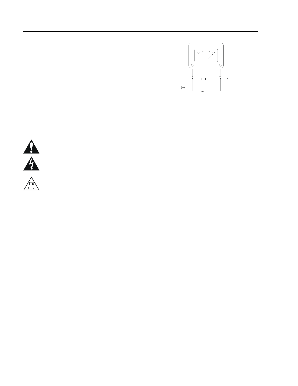
6. After re-assembly of the set, always perform an AC leakage test on all exposed
metallic parts of the cabinet (the channel selector knobs, antenna terminals,
handle and screws) to be sure that set is safe to operate without danger of
electrical shock. DO NOT USE A LINE ISOLATION TRANSFORMER DURING THIS
TEST. Use an AC voltmeter having 5000 ohms per volt or more sensitivity in
the following manner: Connect a 1500 ohm, 10 watt resistor, paralleled by
a .15 mfd 150V AC type capacitor between a known good earth ground
water pipe, conduit, etc.) and the exposed metallic parts, one at a time.
Measure the AC voltage across the combination of 1500 ohm resistor and
.15 mfd capacitor. Reverse the AC plug by using a non-polarized adaptor
and repeat AC voltage measurements for each exposed metallic part. Voltage
measured must not exceed 0.75 volts RMS. This corresponds to 0.5 milliamp
AC. Any value exceeding this limit constitutes a potential shock hazard and
must be corrected immediately.
A.C. Voltmeter
Good Earth Ground
such as the Water
Pipe, Conduit, etc.
0.15uF
1500 OHM
10 WATT
Place this probe
on each exposed
metal part.
X-RADIATION
1. Be sure procedures and instructions to all service personnel cover the
subject of x-radiation. The only potential source of x-rays in current TV
receivers is the picture tube. However, this tube does not emit x-rays when
the HV is at the factory-specified level. The proper value is given in the
applicable schematic. Operation at higher voltages may cause a failure of
the picture tube or high-voltage supply and, under certain circumstances
may produce radiation in excess of desirable levels.
2. Only factory-specified CRT anode connectors must be used.
3. It is essential that the service personnel have available an accurate and
reliable high-voltage meter.
4. When the high-voltage circuitry is operating properly, there is no possibility
of an x-radiation problem. Every time a color chassis is serviced, the
brightness should be run up and down while monitoring the high voltage
with a meter, to be certain that the high voltage does not exceed the
specified value and that it is regulating correctly.
5. When troubleshooting and making test measurements in a product with a
problem of excessively high voltage, avoid being unnecessarily close to
the picture tube and the high voltage power supply. Do not operate the
product longer than necessary to locate the cause of excessive voltage.
6. Refer to HV, B+, and shutdown adjustment procedures described in the
appropriate schematics and diagrams (where used).
IMPLOSION
1. All direct view picture tubes are equipped with an integral implosion
protection system; take care to avoid damage during installation.
2. Use only the recommended factory replacement tubes.
TIPS ON PROPER INSTALLATION
1. Never install any receiver in a closed-in recess, cubbyhole, or closely
fitting shelf space over, or close to, a heat duct, or in the path of heated
air flow.
2. Avoid conditions of high humidity such as: outdoor patio installations
where dew is a factor, near steam radiators where steam leakage is a factor,
etc.
3. Avoid placement where draperies may obstruct venting. The customer
should also avoid the use of decorative scarves or other coverings that
might obstruct ventilation.
4. Wall- and shelf-mounted installations using a commercial mounting kit
must follow the factory-approved mounting instructions. A product mounted
to a shelf or platform must retain its original feet (or the equivalent
thickness in spacers) to provide adequate air flow across the bottom. Bolts
or screws used for fasteners must not touch any parts or wiring. Perform
leakage tests on customized installations.
5. Caution customers against mounting a product on a sloping shelf or in a
tilted position, unless the receiver is properly secured.
6. A product on a roll-about cart should be stable in its mounting to the cart.
Caution the customer on the hazards of trying to roll a cart with small
casters across thresholds or deep pile carpets.
7. Caution customers against using a cart or stand that has not been listed
by Underwriters Laboratories, Inc. for use with its specific model of
television receiver or generically approved for use with TVs of the same or
larger screen size.
8. Caution customers against using extension cords. Explain that a forest of
extensions, sprouting from a single outlet, can lead to disastrous
consequences to home and family.
CM151 GM - SAFETY
i
Page 3
PRODUCT SAFETY SERVICING GUIDELINES FOR AUDIO-VIDEO PRODUCTS
HV SHUTDOW N FOR DIRECT VIEW
THEORY OF OPERATION (SHUTDOW N CIRCUIT)
The HV shutdown circuit appears on sheet 5 of the
schematics for 9-1979. The basic HV shutdown circuit is
illustrated below.
The peak pulse voltage from deflection transformer
TX3204 is rectified by D3205 and C3217. The resulting
37 volts is then divided by RX3015 and RX3019M to
approximately 8.5 volts. It is applied to the
non-inverting input of one of the op-amps in ICX3200
(pin 10). This op-amp is used as a voltage comparitor.
It’s inverting input (pin 9) is held at a reference voltage
of 9.1 voltsby the Zenerdiode ZDX3004 andRX3025.
Any failure in the deflection circuit that would cause
excessively high, High Voltage at the CRT will also cause
an increase in the sampled 37 volts. This increase will
result in an increase in the voltage at the non-inverting
input to op-amp IC3200 (pin 10). When this increased
voltage exceeds its reference 9.1 volts, the op-amp
output goes from low to high. DX3009 provides a
feedback path that holds the non-inverting input high
so that the op-amp stays
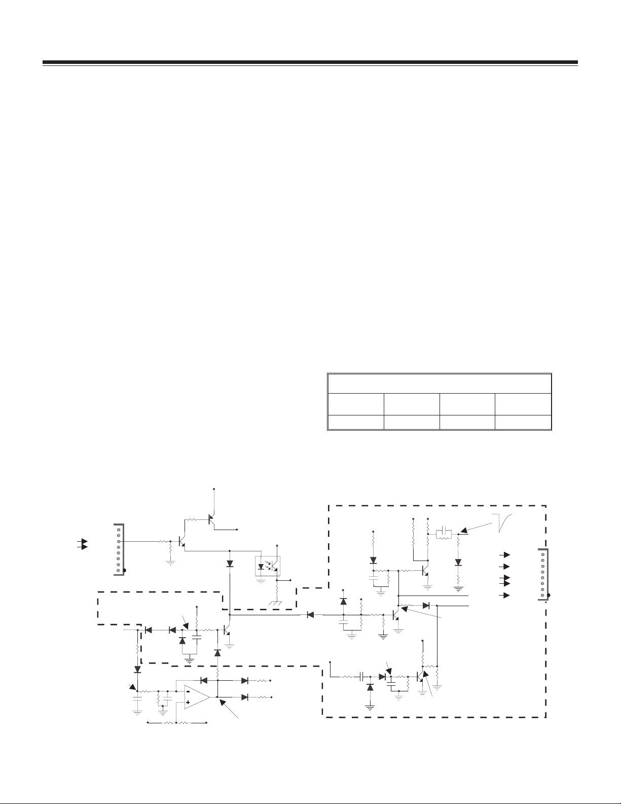
GM Direct View CRT Protection Circuit Diagram
latched with its output high until power is removed by
turning the TV off. DX3009 and RX3016M pull pin 2 of
3N2 high (about 12 volts). This is the horizontal drive
signal pin from the video processor in the small signal
module. The video processor turns off horizontal drive
when its output is pulled high.
When the high voltage shutdown circuit is activated,
IC3200 is no longer supplied with 23 volts to its power
input pin (pin 4) because the 23 volt supply comes from
the deflection transformer, which has been shutdown.
QX3410 and QX3411 provide a connection to another
supply at this time.
The shutdown circuit may be tested for operation by
momentarily connecting a 1k ohm resistor in parallel
with RX3015. This will boost the non-inverting input
above 9.1volts and trigger shutdown.
GM Directview HV & B+
Chassis B+ [VDC] HV (nominal
@ 0 beam kV)
135 32.0 33.0
HV (max @ 0
beam kV)
3A6
PW R CTRL
12VSW
From Small Signal
Module
50VPSW
15VSW
20V
normal
G1
-250V
G1SK
Blank
Daughter Module
A - 17821 - XX
shut down
6.3VAC Fil
Fil. Gnd
Blank
15VSW
To Video Output
Modules
Gnd
250V
G1
nc
3B5
8
1
15VSW
IC3200
1K
CR3405
8
ABL SW
QX3408
Q3000
CR3012
1K
CRX3008
CRX3009
15VSB
1
2
0V = normal
12V = fail
15V Ref
to ICX3401-15
H Drive DR SC
1K
(not used GZ/GM)
1K
4
ICX3405
3
1K
CDisable
To ICX3401-14
SW On
CR3005
CR3006
0.47uF
VSense
PwrCntrl
100
CR3212
15VSW
8.56K
8.56K
CR3001
4.7uF
10uF
+
1.8K
15VSB
+
-
10K
CR3002
10K
1K 1K
15K
2V
with
scan
+
10uF
1K
8
1
CR3003
CRX3012
30V
5.6K
2K
1uF
9.1V
Ref
470
10K
CR3016
CR3004
9.76K
-5V
with
scan
100uF
Q3410
10K
CRX3010
1010
9
110K
390K
330K
1K
Q3001
Q3002
10K
740V
1M
56K
CR3014
15VSW
1K
250V
51K
10K
4.7uF
+-
2.2M
Q3202
10K
L = normal
H = fail
130K
1K
L = normal
H = shut down
CR3210
ii
Page 4

PRODUCT SAFETY SERVICING GUIDELINES FOR AUDIO-VIDEO PRODUCTS
HV SHUTDOW N FOR PROJECTION TV
SERVICE SAFETY NOTES
When servicing chassis, under no circumstance should
the original design be modified or altered without
permission from Zenith Electronics Corporation. All
components should be replaced only with types identical
to those in the original circuit, and their physical
location, wiring, and lead dress must conform to original
layout upon completion of repairs.
Special components are also used to prevent
X-Radiation, shock, and fire hazard. These components
are indicated by the letter “X” included in the item
number. This designates critical components in circuits
which are required to maintain safe performance. No
deviations are allowed without prior approval by the
product compliance and evaluation department.
The circuit diagrams may occasionally differ from the
actual circuit used. This way, implementations of the
latest safety and performanceimprovement changes into
the set is not delayed until the new service literature is
printed.
B+ AND HIGH VOLTAGE SHUTDOW N CIRCUIT
These sets utilizesafety circuits for protection.In case of
a failure involving the seal B+ adjustment, high voltage
adjustment, or high voltage shutdown, follow these
instructions closely. Failure to do so many violate
Federal X-RAY limits. Some sets may use a high voltage
shutdown adjustment potentio in place of fixed
resistors. If it should become necessary to replace one of
these factory controls use only the exact Zenith factory
replacement part number. You must also adjust the
replaced controls to factory specified values (B+ to VDC)
and high voltage adjust to 31.5kV). For the high voltage
shutdown adjustment after replacing the high voltage
shutdown adjustment potentiometer or fixed resistors,
follow the following procedure. A functional test of the
high voltage shutdown circuit must be performed to
check for proper operationif you service these setsin the
shutdown circuitry.
1. Measure the DC voltage across capacitor CX3006. It
should be approximately 7.6VDC. Temporarily
connect a 1K 5% 1/2W resistor across RX3015. High
voltage should shutdown. This checks out the
shutdown circuit operation. Remove the temporary
resistor and recycle the ON/OFF button. A more
elaborate test to determine the actual high voltage
value at which high voltage shutdown will occur can
be made as follows:
Caution: It will normally not be necessary to perform
this test unless the set keeps shutting down
under normal operation, the high voltage
shutdown resistors or adjustment pot had
to be replaced, or the operational test described in the previous paragraph was
unsuccessful. It should be recognized that
significantly elevated high voltage will be
produced during this test and adequate care
should be taken to avoid high voltage
arcing.
2. Connect a 40kV high voltage meter in place on one of
the CRTs at the high voltage block. Connect the
negative lead of a 500mA 12 volt power supply, with
a 1K OHM resistor in series, to the junction of RX3438
and RX3439 and the positive lead to ground side of
RX3439.
Turn the set ON and ensure that the brightness and
contrast are set at minimum. Increase the 12 volt
bench supply until shutdown occurs, Shutdown must
occur in the range from 34.3 to 36.5kV, If not,
shutdown occurs, the circuit must be repaired and
the test repeated.
When you have completed all the adjustments and
tests, use a “hot melt glue” gun to permanently seal
the B+, HV and/or shutdown, if any of these controls
had been used, to render them not adjustable. This is
to ensure continued compliance with the Federal TV
X-RAY Standard.
NOTE: Any board which cannot be repaired to pass
the functional test above should be
exchanged.
iii
Page 5

TABLE OF CONTENTS
Section 1
Overview (General Information) . . . . . . . . . . . 1-1
MBR3457 Remote Control (Keys Defined) . . . . . 1-2
TRK400 Remote Control (Keys Defined) . . . . . . 1-3
Programming Remote . . . . . . . . . . . . . . . . . . 1-4
Remote Control Programming Codes. . . . . . . . . 1-5
Section 2
Service Menu . . . . . . . . . . . . . . . . . . . . . . . 2-1
Servicing Small Signal Module Replacement . . . 2-4
Stereo Coefficients . . . . . . . . . . . . . . . . . . . . 2-5
Projo Convergence Setup MBR3457/TRK4000. . . 2-6
Convergence Setup Worksheet. . . . . . . . . . . . . 2-8
Convergence Setup Illustrations . . . . . . . . . . . 2-9
Section 3
Troubleshooting . . . . . . . . . . . . . . . . . . . . . . 3-1
Servicing. . . . . . . . . . . . . . . . . . . . . . . . . . . 3-5
Service Adjustments . . . . . . . . . . . . . . . . . . . 3-7
GM CRT Assembly . . . . . . . . . . . . . . . . . . . . . 3-9
GM Direct View - Small Signal Diagram . . . . . . 3-10
GM Direct View - Large Signal Diagram. . . . . . . 3-11
GM Projo - Small Signal Diagram . . . . . . . . . . . 3-12
GM Projo - Large Signal Diagram . . . . . . . . . . . 3-13
Section 4
Model Parts List . . . . . . . . . . . . . . . . . . . . . 4-1
Section 5
Mechanical Drawings
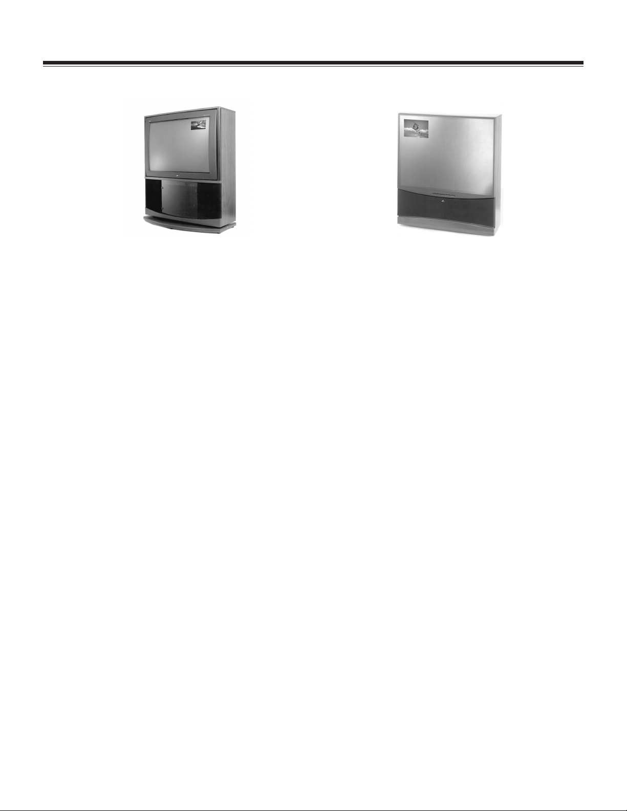
32/36” Stereo Table Top, Exploded View . . . . . 5-1
Inteq Projection Set, Exploded View . . . . . . . . 5-2
46/50” Projection Set , Exploded View. . . . . . . 5-3
56/60” Projection Set , Exploded View. . . . . . . 5-4
Section 6
Schematics and PCBs
Wiring Diagram . . . . . . . . . . . . . . . . . . . . . . 6-1
Interconnect Diagram . . . . . . . . . . . . . . . . . . 6-2
9-1650-02 Single PIP . . . . . . . . . . . . . . . . . . 6-3
9-1650-02 Single PIP PCB Layout . . . . . . . . . . 6-4
9-1689-02 Single PIP . . . . . . . . . . . . . . . . . . 6-5
9-1689 Two Tuner Single PIP . . . . . . . . . . . . . 6-6
9-1689-02 Two Tuner Single PIP PCB Layout . . 6-7
9-1783A IF/Audio . . . . . . . . . . . . . . . . . . . . 6-8
9-1783A IF/Stereo . . . . . . . . . . . . . . . . . . . . 6-9
9-1912/1913/1914 Small Signal Chassis . . . . . 6-10
9-1912/1913/1914 Main Small Signal Carrier . . 6-11
9-1912/1913/1914 Small Signal Audio . . . . . . 6-12
9-1912/1913/1914 Small Signal Chassis . . . . . 6-13
9-1912/1913/1914 Scan Velocity Modulator . . . 6-14
9-1912/1913/1914 Main Small Signal Carrier . . 6-15
9-1920/1922 A/V Switch . . . . . . . . . . . . . . . 6-16
9-1920/1922 A/V Switch & Jackpack . . . . . . . . 6-17
9-1920/1922 A/V Switch . . . . . . . . . . . . . . . 6-18
9-1924 2H Comb Filter . . . . . . . . . . . . . . . . . 6-19
9-1924 Signal Processor . . . . . . . . . . . . . . . . 6-20
9-1924 Video Module PCB Layout . . . . . . . . . . 6-21
9-1925/1927 & 9-2034 3D Comb Filter . . . . . . 6-22
9-1925/1927 & 9-2034 3D Comb Filter . . . . . . 6-23
9-1925/1927 & 9-2034 3D Comb Filter . . . . . . 6-24
9-1925/27 & 9-2034 PCB Layout
3D Comb Filter . . . . . . . . . . . . . . . . . . . . . . 6-25
9-1932 Microcontroller . . . . . . . . . . . . . . . . . 6-26
9-1932 PCB Layout Microcontroller . . . . . . . . . 6-27
9-1934/1935 DV Video Output . . . . . . . . . . . . 6-28
9-1936/1938 Projo Video Output . . . . . . . . . . 6-29
9-1978 Projo Power Supply . . . . . . . . . . . . . . 6-30
9-1978 Projo Power Supply . . . . . . . . . . . . . . 6-31
9-1978 Projo Power Supply . . . . . . . . . . . . . . 6-32
A-17821-05 Projo Supply Daughter Board . . . . 6-33
9-1978 Projo Power Supply PCB Layout . . . . . . 6-34
9-1916/79 Direct View Switch Mode
Power Supply . . . . . . . . . . . . . . . . . . . . . . . 6-35
9-1916/1979 Direct View Deflection. . . . . . . . 6-36
A-18347 Two Tuner Antennas Switch . . . . . . . 6-37
Voltage Waveforms . . . . . . . . . . . . . . . . . . . . 6-38
CM150/PV150 TOC GM CHASSIS
Page 6

Page 7
OVERVIEW
GENERAL INFORMATION
New Video features include a comb filter for processing
incoming signals to provide fine detail images. Auto
skin tone circuitry automatically maintains natural skin
tones. Black level enhancement/white level and peak
white level compression circuitry maintains black/white
contrast ratio and peak luminance level for detail in
both light and dark video areas.
Audio features include SoundRite volume control. This
circuitry automatically compensates for the volume
changes during commercials and limits the audio to a
set volume level.
The BBE featurehas been addedto most audio systems.
The circuitry adjusts the phase relationships of the low,
mid and high frequencies. The circuit also augments the
higher and lower frequencies.
The BBE system provides a dynamic program-driven
augmentation which combines with the phase
compensation feature to restore the clarity of the
original line sound.
THE GM SERIES CHASSIS CONTAINS 10 MODULES
The 9-1912 (small signal) module and 9-1916 (large
signal) are used in the GM-Direct View 32” set.
The 9-1913 (small signal) and 9-1979 (large signal)
modules are used in the GM-Direct View 36” set.
The 9-1914 (small signal) module is used in the
GM-Projo 84 Series.
The 9-1942 (small signal) modules are only used on
GM-Projo 91 Series.
The 9-1943 (small signal) modules are only used on
GM-Projo 98 Series.
All 9-1978 (large signal) modules are only used in
the GM-Projo sets.
THE GM SERIESCHASSIS FEATURES TW ENTY ONE IC’S.
IC6003 EPROM Memory.
IC6002 ROM is the EAROM Memory.
IC6000 Microprocessor located on the 9-1932
Module.
IC3200 Quad Op Amp IC, controlling Pin Cushion/
Over-voltage protect/ Auto Kine Bias/ and ABL, and
is located on 9-1916 and 9-1979 Modules.
IC2900 Audio/Video switch located on A/V 9-1920/
1922 Module.
IC2401M D/A converter for 3D series 9-1925/27,
9-2034 Modules.
IC2400 Digital Comb filter for 2H series.
IC2400M Digital Comb filter for 3D series 9-1925/
27, 9-2034 Modules.
IC2300 Video Processor
IC2200 Signal Processor and handles Video, Sync
and Sweep Drive Processing on 9-1924 Module.
IC2100 Handles Vertical Sweep.
IC2001 PIP Digital Processor.
IC2000 PIP Analog Processor located on the 9-1650
Module.
IC1201 IF/Detector IC
IC1402 BBE Audio Processor
IC1400 Volume Limiter
IC850 Left and right surround sound output IC,
Located on 9-1912/13/14 Modules.
IC800 Left and right audio out put IC, located on
9-1912/13/14 Modules.
ICX3405 Optoisolator IC and is in the Switch Mode
Power Supply.
ICX3402 Regulator IC and is in Switch Mode Power
Supply 9-1978/1979.
ICX3401 Second Regulator IC Controller in the
Switch Mode Power Supply.
CM150/PV150 1-1 GM CHASSIS
Page 8
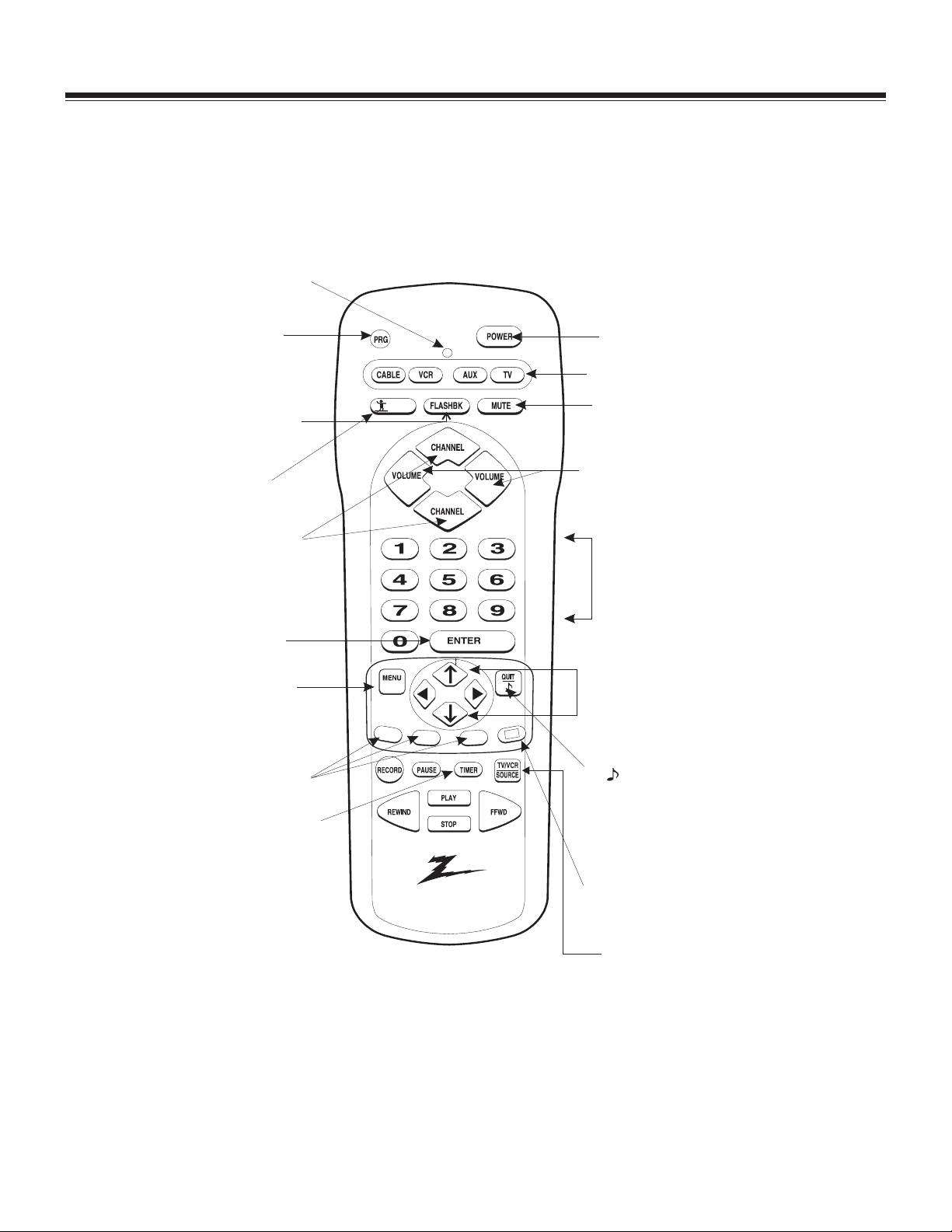
MBR3457 REMOTE CONTROL - KEYS DEFINED
Indicator Light
PRG (Program)
Programs remote to
operate other products.
FLASBK (Flashback)
Returns to previous
channel
SURF
Activates TV channel
"Surf" feature.
CHANNEL (Up or Down)
Selects next channel
When "Surf" option is On,
you receive only channels
set as "Surf" channels.
ENTER
Shows Channel/Time
display. Press after
channel numbers for
fast selection.
MENU
Displays on-screen
menus for TV mode.
A, B, C, KEYS
Special features on
some TV's.
TIMER
Displays the Sleep Timer
Menu. Press repeatedly to
set TV shut-off time. Specifies
AM or PM when you set the
clock or use a timer feature.
SURF
GUIDE
A
B
CC
C
Remote Control Part Number
124-212-37
POW ER
Turn TV On or Off
TV
Selects TV operation
MUTE
Turns sound Off and On
While picture remains.
VOLUME Left/Right
Changes TV's sound
level.
NUMBERS
Selects channels directly
and enter numeric values
for some options.
Up/Down and
Left/Right Arrows
The Up/Down arrows
select options.
The Left/Right arrows
adjust options.
Quit/
Removes on-screen
display from view.
If no display is on,
switches front speaker
surround sound On and
Off for some TVs.
CC (Closed Captioning)
Displays closed caption
menu
TV/VCR - Source
Switches between watching
TV via the available sources,
ANTENNA/CABLE, VIDEO IN, etc.
CM150/PV150 1-2 GM CHASSIS
Page 9
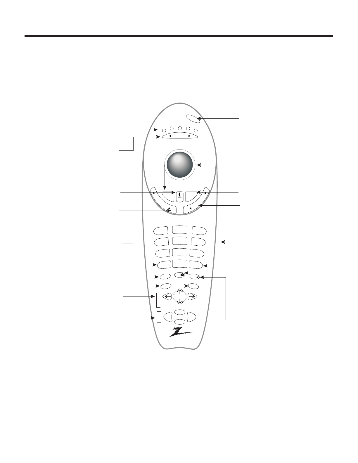
TRK4000 REMOTE CONTROL - KEYS DEFINED
INDICATOR LIGHTS
Illuminate to show which
mode remote is in.
MODE LEFT/RIGHT
Adjust which mode remote
is working in.
MUTE
Press once for Soft Mute, again
for Full Mute, and a third time to
return to normal volume.
SURF
Use the regular channel selection or
customized channel Surf lists.
VOLUME LEFT/RIGHT
Increases/descreases sound level.
SOURCE
Push to switch between
available sources connected to
your Entertainment Machine.
MENU
Displays functions on VCR
RECORD, PAUSE
Control functions on VCR
ARROW KEYS
Allows user to move through
on-screen menu choices.
REW , FFD, PLAY, STOP
Controls functions on VCR
power
cable
aux 1
vcr
tv
mode
aux 2
POW ER
Turn your Entertainment Machine
or any other programmed equipment
on or off, depending on mode
TRAKBALL
Click and move the on-screen pointer.
FLSHBK
mute
v
o
l
u
m
e
surf
flshbk
l
e
n
n
a
h
c
Return immediately to the last
channel viewed.
CHANNEL UP/DOW N
Scroll through your available
channels.
7
menu
record
2
3
5
6
8
9
0
enter
pip
quit/
pause
NUMBER PAD
For direct channel selection
and programming functions.
ENTER
Push to accept menu choices or after
channel numbers for faster transfer.
PIP SNAPSHOT
press to capture and freeze main
1
4
source
picture within large PIP frame. Press
a second time and receive PIP from
another channel or source. Press a
third time to remove PIP.
QUIT
Leaves programming menus and
rew
play
stop
f.fwd
clears screen of displays, and provides
audio swap.
Remote Control Part Number
124-219-01
CM150/PV150 1-3 GM CHASSIS
Page 10

PROGRAMMING THE REMOTES
PROGRAMMING THE MBR3457 REMOTE
If you’re using Zenith products, the remote is already
programmed for the most common codes: TV = 101, VCR
= 201, CABLE= 353, and AUX= 401. For otherbrands, or
if your remote fails to control your Zenith products,
you’ll have to program the remote.
1. Make sure batteries are installed.
2. Press and hold PRG using a blunt pointed object.
Release PRG after indicator light turns on.
3. Press and release button for product being
programmed.
4. Enter 3-digit product code from Remote Control
Programming Codes in this section.
5. Press and release ENTER to save code.
6. Point remote at product and press POW ER to test
product operation. If it does not turn on, reprogram
remote using a different code.
TO AUTO FIND A CODE
1. Turn On the product you want to operate.
2. Press and hold PRG using a blunt object.
3. Press the key to beprogrammed: CATV, VCR, AUX, or
TV.
4. Enter “0-0-0,” then pressENTER within twoseconds.
5. Point remote at the product.
6. Press and release POW ER repeatedly, about once a
second, until your product turns Off.
7. Press ENTER immediately to save the code.
8. Press POW ER to turn On your product.
9. Test your product. If the remote fails to operate the
functions you use mostoften, use Auto Find again to
search for a better code. (Auto Find resumes its
search after thelast code that wasentered and saved
in step 7.)
NOTE: If the indicator light stays on as you press
POWER, Auto Find has tried all of the codes.
If the product you want to control has not
turned off, your remote will not work with
that product.
To cancel Auto Find, press PRG at any time.
PROGRAMMING THE TRK4000 REMOTE
1. Select equipment needed to be programmed, turn to
page2-5tofind the programming code appropriate
for the type and brand of equipment. Make sure the
equipment is turned on.
2. Point the MBR Trakball remote at the piece you’re
programming, press MUTE and FLSHBK at the same
time. Hold until one of the mode indicator LEDs
lights.
3. Use the MODE Right/Left button to select the
appropriate mode for equipment.
4. With the Number Keypad, enter the three digit code
found in step 1 and press ENTER. If the code is
accepted, the mode indicator Led will blink three
times, If it is not accepted, the Led will not blink.
NOTE: The TV and VCR modes will only accept codes
for those types of products. The AUX 1, AUX
2, and Cable modes will accept codes for any
kind of product.
5. Push the POW ER buttonto turn off theequipment. If
nothing happens, repeat the process from step 1,
and try the next code number.
NOTE: To get out of Programming before you enter
a code, just press the QUIT button on remote.
TO AUTO FIND A CODE
1. Turn on device you want to operate.
2. Press and hold MUTE and FLSHBK until the indicator
light turns on.
3. Press MODE Left/Right until the indicator light is
underneath the device needed to be programmed.
4. With the NUMBER keypad, enter the code 0-0-0
(zero-zero-zero), then press the ENTER key right
away.
5. Aim remote at correct device and push the POW ER
button. Allow a second to pass, then push the Power
button again. Repeat until the device turns off.
6. Push Enter to save the code. The indicator light on
the remote willblink three timesand then turnoff.
7. Press Power to turn the device back on.
NOTE: You can get out of Auto Find quickly by
pressing the Quit button.
If the indicator light does not turn off while
you push the Power key, all the codes have
been tried and your device can’t be
programmed.
CM150/PV150 1-4 GM CHASSIS
Page 11
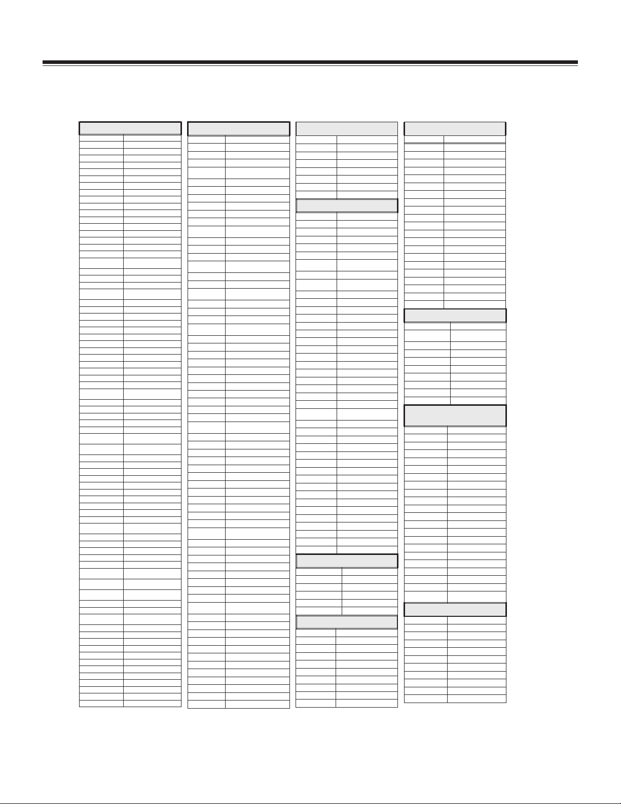
PROGRAMMING CODES MBR3457/TRK4000
PROGRAMMING CODES BY BRAND NAME
TVS
Admiral 116, 121, 130, 133
Adventura TV/VCR 154
Akai 104
Amark 103, 146
AOC 104
Bell & Howell 121
Broksonic 131, 136, 182
Candle 139
Centurion 119
Citizen 121, 139
Contec 141
Coronado 103
Crown 103
Curtis Mathes 116, 119, 121
Daewoo 149, 159
Daewoo TV/VCR 148
Daytron 119
Elektra 121
Emerson 103,104,123,124, 131, 136,
Emerson TV/VCR 158
Fisher 109, 118
Funai TV/VCR 154
General
Electric
Goldstar 103, 104, 119, 147, 184
Goldstar TV/VCR 153
Hitachi 102, 103, 129, 163, 121
Inteq 101
J.C. Penney 104, 110, 114, 117, 119
JVC 125, 132, 164
KMC 103
KTV 103, 104, 138
Kurazai 121
LG 184
Lodgenet 121
Logik 121
LXI 133, 137
Magnavox 103, 112, 113, 117, 119,
Magnavox TV/VCR 173, 181
Majestic 121
Marantz 104, 120, 155
Megatron 146
Memorex 121
MGA/
Mitsubishi
Montgomery Ward 103, 104, 105, 113, 114,
NEC 104, 119
Orion 176
Panasonic 106, 107, 160, 166
Panasonic TV/VCR 174
Philco 103, 104, 112, 113, 139
Philips 112, 113
Pioneer 135
Portland 103
ProScan 116, 157, 162, 167
Quasar 106, 107
RCA 104, 116, 126,
Realistic 105, 123, 124
Sampo 119
Samsung 103, 119, 134, 141
Sanyo 108, 109, 118
Scott 119, 124
Sears 103, 108, 109, 110, 111, 118,
Sharp 103, 105, 122, 133, 137, 156,
Signature 2000 103, 104, 105, 113, 114,
Sony 115, 143, 151, 170
Soundesign 139
Sylvania 112, 113, 117, 119, 127, 128,
Symphonic TV/VCR 15 4
Tatung 106
Teknika 103, 112, 121, 124, 139
Telerent 103, 121
Toshiba 110, 111, 134, 171
XR1000 121, 154
Yorx 119
Zenith 101, 142, 149, 177
Zenith Star Sight 175
Zenith TV/VCR 153, 154, 172
145, 176
106, 107, 114, 116, 117, 161
127, 128, 130, 139, 165
104, 119, 120, 130, 133,
140, 155, 169, 178
119, 121, 130, 133
157,161,162,167,168
134
169
119, 121, 130, 133
139
VCRS
Admiral 208, 261
Adventura 231
Aiwa 231
Akai 223, 238, 241
Audio
Dynamics
Bell & Howell 206, 247
Broksonic 221, 226, 233, 250, 255
Canon 214
Citizen 209
Craig 212
Criterion 239
Curtis
Mathes
Daewoo 244, 246, 248, 254
Daytron 236, 246
DBX 202, 218
Emerson 203, 209, 221, 223, 226, 233,
Fisher 211, 212, 213, 247
Funai 231
General
Electric
Goldstar 209, 273
Go Video 256, 262, 263, 275
Hitachi 215, 231, 257
Instant
Replay
Inteq 273
J.C. Penney 214, 215, 218, 227
JVC 202, 224, 225, 258, 263
Kenwood 202
Logik 239
LXI 209, 231
Magnavox 207, 214, 231
Marantz 207, 218
Marta 209
Memorex 206, 212, 214, 231
Mitsubishi 204, 222, 252, 264
Montgomery
Ward
Multi Tech 239
NEC 202, 218
Optimus 208, 209, 259
Orion 233, 250
Panasonic 214, 251, 259
Pentax 215
Philco 207, 214
Philips 207, 214, 227
Pioneer 210, 215
Portland 246
Pro Scan 216, 260
Quasar 214, 259
RCA 215, 216, 220, 227, 240, 242,
Realistic 206, 208, 212, 214, 231
Samsung 220, 230, 238
Sansui 239
Sanyo 206, 212, 247
Scott 204, 205, 233, 243
Sears 206, 209,211, 212, 215
Sharp 208, 261, 272
Shintom 239
Signature 2000 208, 214, 216, 219, 231, 249,
Sony 217, 232, 237, 274
Sylvania 207, 214, 227
Symphonic 231
Tashiko 209
Tatung 202
Teac 202, 231
Teknika 209, 234
Toshiba 205, 215, 271
XR1000 239
Vector Research 204, 218
Yamaha 202, 218
Zenith 201, 224, 225, 229, 237
202, 206, 218, 247
214, 259
235, 243, 250
214, 216, 220
214, 227
208, 214, 216, 219, 231, 249
244, 260
261
TV/VCR
Hitachi TV/VCR 154
LXI 154
RCA 179
Samsung 180
Sansui 182
Sharp 179
Sylvania 154
CABLE/SATELLITE Set-Ups
Allegro 358, 362
Allegro A/B Switch 36 1
Amerkast 383
Dish Network 389
Gemini 305, 331, 338
General Electric 367
General
Instrument
Hamlin 302, 303, 345, 365, 366
Jerrold 304, 307, 308, 309, 310, 318,
Kale Vision 335
Macom 314, 321
Magnavox 334
NSC 335, 339, 368, 369, 370
Oak 311, 332, 342
Panasonic 313, 320
Paragon 333
Philips 347, 350, 352, 354, 355
Pioneer 315, 343
Primstar 388
Radio Shack 362
RCA DSS 373, 394
Regal 366
Regency 329
Samsung 335
Scientific
Atlanta
Sony DSS 387
Sprucer 313
Standard Comp 335
Stargate 379
Texscan 339, 356, 371
Tocom 317, 318, 346
Toshiba DSS 391
Unika 348, 362
United Satellite 344
Universal 358, 362
Vid Tech 340
Video Way 349
Viewstar 354, 355, 372
Zenith 301, 353
Zenith HD Set Top 385
Zenith N/C Set Top 384, 395
Zenith Satellite 312, 328, 330, 351
305, 306
360, 363
316, 323, 336, 364
LASER DISK
Denon 402, 403
Mitsubishi 403
Pioneer 402, 403, 405
Sanyo 401
Sony 404
Zenith 401
AUDIO CD PLAYERS
Akai 409, 424
Carver 510
Crown 410
Denon 411
Fisher 412, 438
Goldstar 460
Harman/ Kardon 413
JVC 415
Kenwood 412, 416, 417, 441
Magnavox 421, 422, 433, 434
AUDIO CD PLAYERS (continued)
Mitsubishi 423, 424
NAD 425, 426, 447
Nakamichi 427, 428
NEC 429
Onkyo 430
Panasonic 431, 432
Philips 421, 433, 434
Pioneer 431, 435
Quasar 432
Radio Shack 431, 436, 439, 440, 441
RCA 437
Sanyo 438, 439
Scott 440
Sharp 441, 442
Sony 443, 444, 445
Soundesign 461, 498, 501, 502
Sylvania 433
Teac 446
Technics 432, 459
Toshiba 447
Yamaha 448
Zenith 460, 461, 498, 501, 502
AUDIO TAPE DECKS
Denon 455
Harman/
Kardon
JVC 457
Kenwood 450
Onkyo 458
Philips DCC 454
Pioneer 451, 478
Sony 452
Technics 454, 497
Yamaha 453
AUDIO TUNERS
AND AMPLIFIERS
Denon 462, 463
Fisher 464
Goldstar 460
Harman Kardon 465
JVC 466
Kenwood 468, 469, 506
Marantz 472, 503
Onkyo 473
Philips 475, 476
Pioneer 477, 478, 479
Radio Shack 487, 488
Realistic 480
Sanyo 481
Scott 482
Sharp 483
Sherwood 487, 488
Sony 489, 490, 491, 492
Soundesign 461, 498, 501, 502
Teac 494, 495
Technics 497, 509, 567,
Yamaha 496
Zenith 460, 461, 498, 501, 502,
456
504, 505
DVD PLAYERS
Denon 523, 524
Marantz 521
Mitsubishi 525
Panasonic 523, 524
Philips/Magnavox 521
Pioneer 527
Proscan 526
RCA 526
Sony 522
Toshiba 521
Zenith 521
CM150/PV150 1-5 GM CHASSIS
Page 12

CM150/PV150 1-6 GM CHASSIS
Page 13

SERVICE MENU
GM CHASSIS A-LINE LINE SERVICE SETUP DIRECTVIEW AND PROJO
Accessing The Service Menu
You may access the menu by using the keyboard or a
remote control. If you use the keyboard press and hold
the MENU key until the customer menu disappears and
then quickly press the ADJUST RIGHT and CHANNEL
UP keys atthe same time. Ifyou use the remotecontrol
press and hold the MENU key until the customer menu
disappears and then quickly press the number keys 9,
8, 7, 6, and ENTER. Following either procedure should
bring you to the Service Menu. The menu will display
one control at a time. Please note that FACTORY MODE
should always be OFF in the field. If FACTORY MODE is
turned ON there will be situations that cause customer
menu settings to randomly change just by turning the
set off andthen on again.FACTORY MODE canbe turned
OFF simply by setting the clock feature in the customer
menu.
Please note color tracking is done by the Video
Processing circuit. There are no manual color controls.
Even if COLOR LEVEL, on the customer menu, is turned
all the way down there will always be some color on
(unless the video signal is black and white with no
color burst).
A-18728-04 1.30
EPROM
Part Number
09 Horz Pos 12
Menu
Item
Item
Name
02/05/97
Software
version
Current Setting
Software
version
TE = 10110000
MENU TERMS GLOSSARY
The items listed below are Service Menu items you may
have to adjust for a particular television. Please note
that some of these, if set wrong, may cause symptoms
similar to a circuit failure.
AC Pwr ON - Turns set on when AC line power is
applied. Power key is disabled. Automatically enabled
if factory mode is on.
Audio Coefficients (VCO addition, SAP VCO, SAP LPF,
LPF addition, Spectral, and W ideband) - Settings for
the audio processor’s stereo decode system. Values, for
Service Menu features 74 through 80, are found on a bar
code label on top of the Tuner/IF/Audio module.
A/V Lock - Disables all audio and video inputs - gives
blue screen and menus only.
Band/AFC - Allows setting of tuning band and AFC
mode. Allows manual override of the BAND and AFC
selection of Auto Program.
Note: If Auto Program is run, it will automatically
reset the manual BAND/AFC selection.
Bright AUX and Bright RF - Allows balance of AUX and
RF viewed video brightness levels.
Chan Lock - Locks set to one channel use only.
Feat. Level - 0 =11 jack,1=18jack,2=21jack. Factory
mode must be onto switch the setting. Aftermaking the
change be sure to turn off the factory mode feature.
Horz Pos and Vert Pos - Sets horizontal and vertical
position of on screen displays. Does not affect position
of the picture video.
Key Deft - Disables menu use of the keyboard keys:
MENU, ENTER, ADJUST, and SELECT.
Max Vol - Sets maximum volume limit.
Min Vol - Sets minimum volume limit.
Preset PX (also Theater, Game, Sports, Daylight, and
W eak) -Stores special customer video menu setup assix
different presets. To change, enter the customer video
menu and select video pref. feature. Select preset (i.e.
Preset, Theater, Game, etc.) that is to be changed and
customize it. Enter the Service Menus and access the
feature that was just changed (Preset PX, Theater PX,
Game PX etc.) and press adjust to store the change. The
new setup is stored as the new “video controls preset”
for that item.
Proj Mode - When enabled, adds the Projo Setup feature
to the customer setup menu. Enables customer static
setup (red and blue centering offset) display for the
projo TVs.
RGB Brite and RGB Cont - Controls on screen display
video.
Sub Contr -Sets operating rangeand offset ofcontrast.
CM150/PV150 2-1 GM CHASSIS
Page 14

SERVICE MENU
GM Service Menu A-18728-03 Ver. 1.30
INTEQ INTEQ AVI AVI INTEQ
32V DV 36V DV ‘84 PV ‘91 PV ‘98 PV
3D comb 4x5W 3D comb 4x5W 2H Comb 2x5W 2H Comb 4x5W 3D comb 4x5W
0 Factory Mode 11111
1 Preset Preset N/A N/A N/A N/A N/A
2 Theater Preset N/A N/A N/A N/A N/A
3 Game Preset N/A N/A N/A N/A N/A
4 Sports Preset N/A N/A N/A N/A N/A
5 Daylight Preset N/A N/A N/A N/A N/A
6 Weak Signal Preset N/A N/A N/A N/A N/A
7 Vert OSD Position 15 15 15 15 15
8 Horz OSD Position 44 44 44 44 44
9 Keyboard Defeat 00000
10 Channel Lock 00000
11 Minimum Volume 00000
12 Maximum Volume 63 63 63 63 63
13 AC Power On 00000
14 A/V Lockout 00000
15 Feature Level 22012
16 Band/AFC 00000
17 Projection Mode 00111
18 Horz Gemstar Pos 00000
19 Vert Gemstar Pos 00000
20 RGB OSD/PIP Brightness 45 45 45 45 45
21 RGB OSD/PIP Contrast 60 60 50 50 50
22 Base Brightness Rf 76 76 76 76 76
23 Base Brightness Aux 76 76 76 76 76
24 Base Brightness YUV 76 76 76 76 76
25 Sub Contrast Rf 16 16 16 16 16
26 Sub Contrast Aux 16 16 16 16 16
27 Sub Contrast YUV 16 16 16 16 16
28 Sub Color Rf 10 10 10 10 10
29 Sub Color Aux 10 10 10 10 10
30 Sub Color YUV 10 10 10 10 10
31 Low Green/Red Drive 103 103 90 90 90
32 Med Green/Red Drive 117 117 80 80 80
33 High Green/Red Drive 113 113 70 70 70
34 Low Blue Drive 37 37 30 30 30
35 Med Blue Drive 51 51 40 40 40
36 High Blue Drive 57 57 50 50 50
37 Low Red Cutoff 200 200 195 195 195
38 Low Green Cutoff 100 100 230 230 230
39 Low Blue Cutoff 89 89 121 121 121
40 Med Red Cutoff 180 180 175 175 175
41 Med Green Cutoff 100 100 230 230 230
42 Med Blue Cutoff 118 118 141 141 141
43 High Red Cutoff 168 168 165 165 165
44 High Green Cutoff 100 100 230 230 230
45 High Blue Cutoff 144 144 159 159 159
46 Custom Color Setup 10 10 10 10 10
47 Preset Color Setup 10 10 10 10 10
48 Theater Color Setup 14 14 14 14 14
49 Game Color Setup 10 10 10 10 10
50 Sports Color Setup 10 10 10 10 10
51 Daylight Color Setup 10 10 10 10 10
52 Weak Sig Color Setup 10 10 10 10 10
53 Custom Black Stretcher 33333
54 Preset Black Stretcher 33333
55 Theater Black Stretcher 33333
56 Game Black Stretcher 33333
agmchas/p1 2-2
Page 15

SERVICE MENU
GM Service Menu A-18728-03 Ver. 1.30 (continued)
INTEQ INTEQ AVI AVI INTEQ
32V DV 36V DV ‘84 PV ‘91 PV ‘98 PV
3D comb 4x5W 3D comb 4x5W 2H Comb 2x5W 2H Comb 4x5W 3D comb 4x5W
57 Sports Black Stretcher 27 27 27 27 27
58 Daylight Black Stretcher 33333
59 Weak Sig Black Stretcher 33333
60 Black Level Priority 00000
61 Color Decode Phase/Gain 169 169 169 169 169
62 OSD Control 00000
63 DVD YUV Tint Offset 63 63 63 63 63
64 Luma Setup 194 194 194 194 194
65 VSM Phase/Gain 70 70 70 70 70
66 DC Restoration 00000
67 Dynamic ABL Point Gain 22222
68 ABL Point/Gain 56 56 56 56 56
69 Horz Video Position 22 22 16 16 16
70 Vert Freq (Auto/60Hz) 22222
71 TOF Freq/Q 00000
72 PIP Horz Position 128 128 112 112 112
73 Input Level 66666
74 * VCO Adjust 31 31 31 31 31
75 * SAP VCO (Always 0) 00000
76 * SAP LPF (Always 0) 00000
77 * LPF Adjust 26 26 26 26 26
78 * Spectral Adjust 35 35 35 35 35
79 * Wideband Adjust 39 39 39 39 39
80 * Bass Boost 00000
* These settings must match the bar code label on top of the 9-1789 module.
CM150/PV150 2-3 GM CHASSIS
Page 16
SERVICING - SMALL SIGNAL MODULE REPLACEMENT
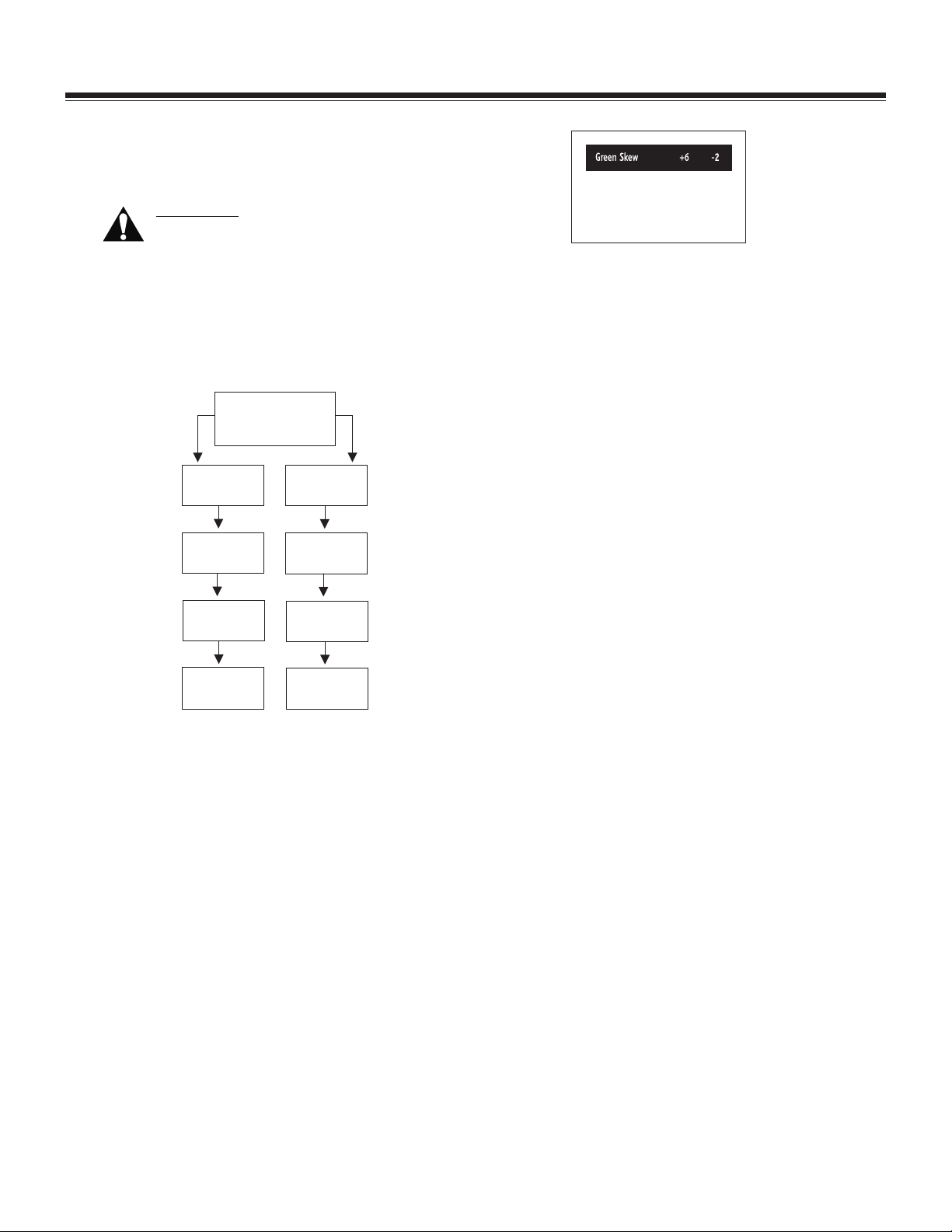
SMALL SIGNAL (MAIN) MODULE REPLACEMENT
AND TOUCHUP CONVERGENCE
IMPORTANT! All convergencedatais stored in
IC6002, the eight pin Serial EEPROM located
on the Micro Module. A complete re-conver-
gence will be required unless this data is
retrieved fromtheoriginalmodule either by recording
the convergence values or transferring IC6002 to the
replacement module.
Small Signal Replacement Convergence Procedure
Replacing Small
Signal Module
Dead Set
Transfer IC6002
from original
Module
Record convergence
values to worksheet
Set has OSD Display
Record convergence
values to worksheet
Install convergence
values or transfer
IC6002 to new
Module
Green Convergence Mode Display
3. Start by pressing 1 on remote. Write down the
convergence values on the Digital Convergence
Numbers For Rear Projo TV sheet provided. Where
there are more than one set of numbers, press the
number again to see the second set.
4. After all the Green settings have been recorded,
press MUTE to access the Blue settings. Repeat
procedure and record all of the BLUE settings. When
BLUE is finished, press SURF for RED and record all of
the RED settings.
5. When all of the settings have been recorded, press
QUIT to exit the Convergence Mode.
NOTE: REMEMBER - Avoid any mechanical adjust-
ments on the CRTs or adjustment of the
Horizontal and Vertical size controls on the
Power Supply Module, if only replacing the
Main Module.
Proceed with
minor convergence
Proceed with
minor convergence
NOTE: If the small signal (Main) Module is the
cause of a Dead Set condition, and IC6002 is
faulty, the replacement module may require
a complete convergence setup.
If set still has on-screen display, use the following
procedure:
1. Remove shield from the Micro Module on the
original Small Signal Module and the replacement
module. Remove IC6002 from original module and
exchange it with IC6002 from the replacement
module. Replace both shields making sure to reinstall IC6002 on DUD Module.
2. Press and hold MENU on remote until User Menu
display disappears. Then press “999" and ENTER.
Set will now be in the GeometryAdjustment Mode; it
is not necessary to save GEOMETRY settings. Press
FLASHBACK to access the Green Convergence Sett ings. The left side of the bar describes the adjustment name. The two numbers on the right side of
the bar are the Horizontal and Vertical settings:
Horizontal on the left and Vertical on the right.
6. Remove defective module and install replacement
module. Ensure that all connectors are plugged in
securely.
7. Place the set in the Convergence Mode and install all
of the convergence values. Start with Green and
follow with Red, then Blue.
NOTE: To save the convergence values just entered,
press QUIT. “Do You Want To Save The
Changes - YES/NO” will appear. Use the
ADJUST button to select YES or NO, then press
ENTER to save. Do this after each “Green,
Red, Blue” sequence to avoid losing all of
your work should a power interruption occur.
8. If, after installing all of the original values, set still
needs some touchup of the convergence, attach a
crosshatch generator to set and follow the procedure
provided. Use the small Left/Right arrows for horizontal adjustments and the small Up/Down arrows
for vertical adjustments. Pressing ENTER lets you
toggle between the control’s stored setting and the
adjustment just made.
9. Access the Service Menu and enter the Stereo
coefficients as shown on the bar code label on small
signal Module.
agmchas/p1 2-4
Page 17

SERVICE - SMALL SIGNAL MODULE REPLACEMENT (continued)
ENTER THE STEREO COEFFICIENTS
(Bar code data) Will be found on a label attached to the
chassis. Enter these settings in their appropriate
locations in the Service Menu items 74 through 80
(starting with the left-most two digits for item 74)
TYPICAL CHASSIS BAR CODE LABEL
LOCATED ON THE MAIN MODULE
COEFFICIENTS
SERVICE MENU ITEMS
06 19 06 07 18 61 34
74 75 76 77 78 79 80
0370v
CM150/PV150 2-5 GM CHASSIS
Page 18

PROJO CONVERGENCE SETUP PROCEDURE - MBR3457/TRK4000
Skew
* Key/D Key
* S-ing/W-M
In Pin
Mid Size
DC Center
Convergence Function Keys
SURF
Day
GUIDE
THEME
PIP
PIPch
Remote Control Part Number
124-212-37
H
TO DO
FREEZ
Green Convergence Select
Blue Convergence Select
Bow
* Lin/In Lin
* Pin/D Pin
* Size/L Size (Green & Red)
* Size/R Size (Blue)
* L Lin/L Edge (Green & Red)
* R Lin/R Edge (Blue)
Exit Setup Mode
Red Convergence Select
Convergence Mute
Skew
*Key / D Key
*S-ing / W -M
In Pin
Mid Size
Convergence Mute
DC Center
+/- Vertical
Control
Adjustments
Convergence Function Keys
power
cable
aux1
vcr
mode
mute
surf
e
2
5
8
0
pip
play
rew
stop
124-219-37
flshbk
aux2
Blue Convergence Select
Red Convergence Select
l
e
n
n
a
h
c
3
6
9
enter
quit
pause
f.fwd
tv
v
o
l
u
m
1
4
7
source
menu
record
Remote Control Part Number
Green Convergence Select
Bow
*Lin / In Lin
*Pin / D Pin
*Size / L Size (Green & Red)
*Size / R Size (Blue
*L Lin / L Edge (Green & Red)
*R Lin / R Edge (Blue)
Toggles between new and
stored convergence
Exit Setup Mode
+/- Horizontal
Control
Adjustments
To simplify thePTV convergence procedure, a Kitwith
a special hand control may be purchased. Refer to the
back page of this Service Manual for more
information.
GM - PROJO CONVERGENCE SETUP PROCEDURE
Step 1: W arm-up TV set for at least 15 minutes.
1. Read entire procedure while set is warming up.
Note: G-2 setup and video mute jumpers are on the
rear left corner of the main module. G-2 and
Focus controlsarelocatedinside the back of the
projo behind the blue CRT. Vertical and
horizontal size controls are located on the front
of the power supply/deflection module.
Step 2: G-2 Setup
1. Place G-2 Setup jumper (SW1) to setup position.
2. Set G-2 control for the Green CRT by turning control
clockwise until vertical retrace lines are just visible.
Repeat procedure for red and blue.
Note: Make Sure that there is no direct light on screen
or bright light present while adjusting G-2
controls.
3. Place SW1 to normal position.
Step 3: Focus Adjustment
1. Connect a pattern generator (or VCR with signal
pattern tape part#892-53) to videoinputs on set.
2. Set pattern generator display to a hatch or
mono-scope pattern.
3. Adjust brightness and contrast, on the Customer
Video Menu, to lowest level that allows you to view
entire pattern.
4. Adjust mechanical and electricalfocus as needed.
Note: The area of interest while doing mechanical
focus is the center of the screen. The areas of
interest while doing electrical focus are mid
points of the display (midway between center
toedge on thetop, bottom, andbothsides).
Step 4: Customer Convergence Controls
1. Using customer convergence controls, adjust
vertical and horizontal RED and BLUE static
convergence controls to the center of their +/range.
Step 5: Setup Yoke Tilt and Center Screen
1. Select cross hair pattern on the generator.
2. Press and hold MENU on remote until customer
menu display disappears. Then press “999ENTER”.
Geometry convergence display will appear.
3. Press PIP for TRK4000 or FREEZE for MBR remote
to disable convergence. Screen should now say
Geometry MUTE.
agmchas/p1 2-6
Page 19

PROJO CONVERGENCE SETUP PROCEDURE - MBR3457/TRK4000 (continued)
4. Locate physical center of display screen.
5. Look at horizontal line and adjust by loosening yoke
clamp and rotating yoke assembly.
6. Using ring magnets set Green CRT beam to center
point of screen.
7. Adjust Red horizontal line to convergencewith Green
horizontal line and Red vertical line 3/4" to right of
Green vertical line. Repeat steps 5 and 6 for Blue
horizontal and vertical line.
8. Adjust Blue horizontal line to convergence with
green horizontal line and blue vertical line 3/4" to
left of green vertical line.
9. Press PIP for TRK4000 or FREEZE for MBR remote to
enable convergence. The Geometry MUTE display
should be off.
10. Mute (cutoff) Red and Blue CRT video by placing
jumpers of SW2 (on the main module) to disable
position.
11. Looking at the Green - notice if pattern changed
coordinates. If yesgo to step12. If nogo to step13.
12. Press Menu + FLASHBK on remote. Screen should say
Green DC. Use small arrows on remote to adjust Green
centering.
13. Enable Red CRT video,by removing RED disablejumper
of SW2. Press SURF + Menu for TRK or CC + Menu for
MBR remote to select Red DC and convergence Red to
Green.
14. Enable Blue CRT video, by removing BLUE disable
jumper of SW2. Press MUTE + Menu to select Blue DC
and convergence Blue to Green.
Step 6: Setup Green Reference Color
1. Disable Red and Blue CRT video using the jumpers of
SW2 (on the main module) .
2. Press FLASHBK + 6 on remote. Screen should say
Green Size. Use small arrows on remote to set Horz. &
Vert. size to 127.
3. On the sweep module adjust vertical and horizontal
size controls to about 1.5" of over scan. Display
aspect ratio must be 3 to 4.
4. Adjust vertical controls to obtain straight horizontal
lines.
5. Adjust horizontal controls to obtain straight vertical
lines.
6. Repeat steps 2-5, as necessary, to achieve best
possible display.
Note: If you have a monoscope test pattern set
horizontal size to 5 graticule marks (left and
right) and vertical size to 4.0 graticule marks
(top and bottom).
Some remote control keys have two functions.
Press key a second time to toggle to second
function.
Step 7: Converge Red onto Green
1. Enable Red CRT video by removing RED disable
jumper of SW2. Blue CRT should still be disabled.
2. Adjust vertical controls to obtain straight horizontal
lines.
3. Adjust horizontal controls to obtain straight vertical
lines.
4. Adjust L-Lin, L-Edge, L-Size, and Mid-Size to fully
converge the Red image to the Green image .
5. Repeat steps 2-4, as necessary, until best possible
convergence is achieved.
Step 8: Converge Blue onto Green
1. Enable Blue CRT video by removing BLUE disable
jumper of SW2 and disable Red CRT video by
installing RED disable jumper of SW2.
2. Adjust vertical controls to obtain straight horizontal
lines.
3. Adjust horizontal controls to obtain straight vertical
lines.
4. Adjust R-Lin, R-Edge, R-Size, and Mid-Size to fully
converge Blue image to Green image.
5. Repeat steps 2-4, as necessary, until best possible
convergence is achieved.
Step 9: Final Convergence of Red and Blue to
Green
1. Enable Red CRT video and Blue CRT video by
removing RED and BLUE disable jumpers of SW2.
2. Adjust the convergence controls, as necessary, until
best possible convergence is achieved.
Step 10: Save Convergence Adjustments
A question will be displayed, Do You Want To Store Your
Changes - YES/NO, when QUIT is pressed once. Using
ADJUST key, change and high light to YES, and press
ENTER to save. You may also press QUIT twice to exit
the convergence setup mode without saving changes.
CM150/PV150 2-7 GM CHASSIS
Page 20

CONVERGENCE SETUP W ORKSHEET
Use this chart to record the Red, Green, and Blue convergence setting values. You do not
need to copy the "Geometry" settings as they are the result of the red, green, and blue
settings. This chart is useful if you have to change a main module and still have a working
video display.
Check the setup section of this manual for the convergence procedure details.
FLASHBK
1
2
3
4
5
6
7
8
9
0
MENU
SURF
1
2
3
4
5
6
7
8
9
0
MENU
Green
Skew
Bow
Lin
Key
Pin
Size
In-Pin
S-ing
L-Lin
Mid-Size
DC Center
Red
Skew
Bow
Lin
Key
Pin
Size
In-Pin
S-ing
L-Lin
Mid-Size
DC Center
N/A
Horz.
N/A
Vert.Horz. Vert.Horz.
Green
N/A
N/A
In-Lin
D-Key
D-Pin
L-Size
N/A
N/A
W-M
L-Edge
N/A
N/A
N/A
Vert.
N/A
Red
N/A
N/A
In-Lin
D-Key
D-Pin
L-Size
N/A
W-M
L-Edge
N/A
N/A
Horz.
N/A
N/A
N/A
N/A
Vert.
N/A
N/A
N/A
MUTE
1
2
3
4
5
6
7
8
9
0
MENU
Blue
Skew
Bow
Lin
Key
Pin
Size
In-Pin
S-ing
L-Lin
Mid-Size
DC Center
Horz.
N/A
Vert.
N/A
Blue
N/A
N/A
In-Lin
D-Key
D-Pin
R-Size
N/A
W-M
R-Edge
N/A
N/A
Horz.
N/A
Vert.
N/A
N/A
N/A
CM150/PV150 2-8 GM CHASSIS
Page 21

CONVERGENCE SETUP ILLUSTRATION
0
These functions
8b
8a
7
6a
5b
MID-SIZE
are used for
Red and Blue only.
W-M
S-ING
IN-PIN
SIZE
D-PIN
6b
9b
9a
3b
MID-SIZE
L-SIZE
L-EDGE
L-LIN
IN-LIN
IN-PIN
D-PIN
(Red controls are as show.
Blue will control the right side.)
Red Focus
Green Focus
Blue Focus
LOCATED ON FRONT OF SWEEP MODULE
Focus Block
(USED FOR GREEN SETUP ONLY)
Red G2
Green G2
Blue G2
(R2104) (R3227)
Vert. Size Horiz. Size
CONVERGENCE CONTROL ILLUSTRATIONS
5a
4b
3a
2
4a
1
PIN
D-KEY
KEY
LIN
BOW
SKEW
PIN SIZE
D-KEY
KEY
LIN
BOW
SKEW
(Arrows indicate area(s) of interest)
ZONE B ZONE A
CONVERGENCE ZONES
- 15.2 cm (6") Remaining Area
46"
CONVERGENCE SPECIFICATIONS
(6.75") Remaining Area
- 17.1 cm
52"
Zone A
- 13.2 cm (7.8") Remaining Area
60"
required that in the worst case the images to at least touch.
Note: Zones A require the best convergence. In Zone B it is
Zone B
CM150/PV150 2-9 GM CHASSIS
Page 22

CM150/PV150 2-10 GM CHASSIS
Page 23

TROUBLESHOOTING
TROUBLESHOOTING THE GM TELEVISION SYSTEM
A system is easier to troubleshoot when broken down
into circuit groups. A blank display with no audio does
not necessarily mean you are working with a dead set.
Make adjustments after you isolate the problem. Do not
start troubleshooting by turning pots or using other
service controls.
Start your checks by verifying the status of standby
conditions, power on start conditions, sweep start
conditions, and then check video and audio system
conditions. The most basictest aids to use, ifthe set has
sweep and audio(controllable noise), are themenus and
a VCR. If there is no sweep or high voltage, then you
must make some measurements to isolate the cause to
an area of the system.
It is recommended that you perform troubleshooting in
this order: power supplies, horizontal sweep/high
voltage, vertical sweep, video, and audio.
The list of service checks on the following pages takes
you from standby to power and sweep on conditions.
Where possible, you have been given both DMM (digital
multi-meter) readings and oscilloscope observations for
the active signal checks.
For most active signal checks and DC voltage measurements, use the right end of RX3401 in direct view
products and the left end of RX3401 in projection
products for the DC common side of your meter or
scope. To takemeter readings onthe primary sideof the
switch mode power supply, use front lead of RX3437 in
direct view products and the jumper W-3 in projection
products for the meter AC common.
If the audio26VSW (connector 3K9) is missing, you may
have partial or distorted audio. The audio system is
powered by supplying 15VSB to the audio power
amplifiers, via Q4001 and Q4002, during power on until
the audio 26VSW turns on. 15VSW is supplied to IC800
and IC850 via CR801 and CR850, which prevents audio
noise during power on. When the audio 26V is present,
CR801 and CR850 back bias, preventing the 15VSW and
26V from mixing. CX848 and CX856 are kept charged to
prevent audio noise during power off.
A Line GM Chassis Power Control
Directview
15VDCTL
15V SB
PW R CTRL
12V SW
37V SBY
PW R FA
GND
GND
HORZ DRV
VERT DRV
<15.5V>
<0V>
<0V>
<37.7V>
< > = STBY ( ) = PW R ON
2G3-3
MAIN
MODULE
1
6A3
2N3-2 3N2-2
8
CM150/PV150 3-1 GM CHASSIS
Not Used
(15V)
(4.2V)
(11.8V)
(37.4V)
(37.4V)<37.7V>
3.5V p-p or 1.5V rms
4.0V p-p or
8
3A6
1
PW R SUPPLY
SW EEP
MODULE
3G2-2
Page 24

TROUBLESHOOTING
GM A Line Directview TV
POW ER UP CHECKS - DEAD SET SW EEP/HV CHECKS - DEAD SET
Check Standby Conditions
Power Supply
150VDC - RX3401
15VSB - D3414
37VSB - ICX3404 pin4
PwrFa - W 37
YES
Check Standby Conditions
Main Module
5VSB - R4108
YES
Power ON Conditions
Main Module
5VSW - W 9
YES
Power ON Conditions
Power Supply
4.3VDC - W 47
YES
Power ON Conditions
Power Supply
130VDC - L3401
Check AC Power
Then Replace
(E4)
(E2)
(E3)
(E2)
(C2) (D1)
(B1)
(C2)
(F3)
NO
NO
NO
NO
NO
Power Supply
Check 6A3 Cable
Then Replace
Main Module
Replace
Main Module
Check 6A3 Cable
Then Replace
Power Supply
Replace
Power Supply
(E1)
Sweep ON Conditions
Power Supply
H DRV - QX3206 C
40V p-p
YES
Sweep ON Conditions
Power Supply
265VDC - RX3277
NO
Check CRT and Video
Output Module.
Check 2N3 Cable
NO
(F2)
# = H DRV can also be checked
on top of the 9-19
2N3 pin 2
(H4)
YES
CRT &
9-1934/35
OK
Then Replace
Main Module
Check System
For Video
Shut Down
Replace
Power Supply
(G1)
CM150/PV150 3-2 GM CHASSIS
Page 25

TROUBLESHOOTING
GM A Line Chassis Power Control
Projection
2G3-3
MAIN
MODULE
1
15VDVCNTL
15V SB
PW R CTRL
Not Used
<16.35V>
<0V>
8
(15.9V)
(3.7V)
PW R SUPPLY
12V SW
6A3
8
2N3-2 3N2-2
37V SBY
PW R DD
GND
GND
< > = STBY ( ) = PW R ON
HORZ DRV
VERT DRV
<0V>
<39.5V>
3.5V p-p or 1.5V rms
4.0V p-p or
(11.8V)
(37.4V)
(28.8V)<27V>
3A6
1
SW EEP
MODULE
3G2-2
CM150/PV150 3-3 GM CHASSIS
Page 26

TROUBLESHOOTING
GM A Line Projection TV
POW ER UP CHECKS - DEAD SET SW EEP/HV CHECKS - DEAD SET
Check Standby Conditions
Power Supply
150VDC - CR3402 C
15VSB - L3416
37VSB - CR3488 cath
PW RFA - R3442
YES
Check Standby Conditions
Main Module
5VSB - R4108
YES
Power ON Conditions
Main Module
5VSW - W 9
YES
Power ON Conditions
Power Supply
3.8VDC - R3432
YES
Power ON Conditions
Power Supply
115VDC - RX3437 left end
Check AC Power
(F5)
NO
(E6)
(E6)
(E5)
(C2) (E5)
NO
NO
(C2)
(E6)
NO
(E4)
NO
Then Replace
Power Supply
Check 6A3 Cable
Then Replace
Main Module
Replace
Main Module
Check 6A3 Cable
Then Replace
Power Supply
Replace
Power Supply
(E5)
Sweep ON Conditions
Power Supply
H DRV - R3264
4V p-p / 1V AC
YES
Sweep ON Conditions
Power Supply
250VDC - RX3206
NO
HV ON Conditions
Power Supply
Unplug 4F
250VDC - RX3206
NO
HV ON Conditions
Power Supply
47 - 52K ohm - 4F
YES
Replace
Power Supply
Also Check CRTs Also Check CRTs
NO
(G2)
# = H DRV can also be checked
on top of the 9-1642/1645
2N3 pin 2
(G4)
YES
(G4)
YES
(E3)
NO
Check 2N3 Cable
Then Replace
Main Module
Check System
For Video
Shut Down
Replace
Focus Block
Replace
Focus Block
250VDC - RX3206
Replace
Power Supply
(G2)
(G4)
NO
CM150/PV150 3-4 GM CHASSIS
Page 27

SERVICING
GM DIRECTVIEW SERVICE CONTROLS
The service menu controls are limited to the G-2, focus,
vertical size, and horizontal size. There are controls on
the Tuner/IF/Audio Processor module but you will not
be able to access these.
The service menu is another part of the service
adjustments. Checking theservice menu setup must bea
part of normal servicing. The sheer number of items
should not concern you as only some of them may
require field adjustment. All the remaining items should
be set to the recommended value or setting and not
changed.
Display Size Controls
VR2138 Vertical Size - Adjust for 1/2" of overscan. Be
careful not to cut off the closed caption display video
area.
VR3249 Horizontal Size - Adjust 1/2" of overscan. Be
careful not to cut off the closed caption display video
area.
G-2 and Focus Controls
G-2 Setup - On the video output module short the pins
of SETUP connector(near connector 5F2). This will
disable the videodrive to theCRT. Adjust theG-2 control
until retrace lines are just visible. Remove the short
from the SETUP connector for normal video operation.
Focus Setup - Adjust as needed after setting G-2. This
will be affected by the setting of G-2. The setting of G-2
will also affect the tint (green to blue) of peak video
white.
make the convergence alignment adjustments in the
following order:
Display size and lens focus
G-2 and electrical focus
Yoke for tilt and centering
Adjust convergence controls as required.
Display Size Controls
The size controls are located at the front edge of the
power supply/sweep module. Ifthe projo has a VCRshelf
you must remove the panel, under the VCR shelf, to
access the size controls on the front of the Sweep/SMPS
assembly (there areseveral screws holdingthe panel).
Using a cross hatch pattern adjustR3227 horizontal size
and R2104 vertical size for 1.5" of over scan. If youhave
mono scope test pattern (service pattern signal
generator VCR tape #892-53) adjust R3227 horizontal
size for 4.5 tic marks (left and right) and R2104 vertical
size for 4.0 tic marks (at top and bottom).
Set Main Size Pots First
Front of Sweep Module
Vert. Size
R2104
Horz. Size
R3227
GM PROJECTION SERVICE CONTROLS
The service controls are limited to the service menu,
G-2, focus, vertical size, horizontal size, yoke ring
magnets, and the convergence controls. There are
controls on the Tuner/IF/Audio Processor module but
you will not be able to access them.
Make checking the service menu part of servicing GM
projection systems. In addition to theitems mentioned,
in the directview notes, the Projo Mode feature, of the
service menu, enables or disables the Projo Setup
feature on the customer menu. The Projo Setup feature
adds a horizontal and vertical centering offset to the
convergence drive of Red and Blue. This feature’s
horizontal and vertical settings must be centeredbefore
doing convergence alignment.
If you have changed a CRT, the convergence module,
adjusted the mechanical focus of the CRT lens, or have
adjusted the size you may need to check the
convergence alignment. It is recommended that you
CM150/PV150 3-5 GM CHASSIS
Convergence G-2 Setup and Video Cutoff Jumpers
The CRT video cut off and G-2 setup jumper assemblies
are located on the left rear corner of the main module.
These jumpers are used to mute red, green, or blue video
individually and cutoff all video drive to the CRTs for G-2
setup.
SW2 contains the blue, green and red video mute (or
video cut off ) jumpers. All jumpers of SW2 must be in
the normal position for doing G-2 setup. SW1 is the G-2
setup jumper.
G-2 Setup
This procedure should not
the screen or in a brightly lighted room. When you are
setting G-2 this sets the conduction point of the CRT.
G-2 is not used to set picture brightness level. Be sure
that all of the video mute jumpers (SW2) are in the
normal position. Havingone or moreof the CRTsin video
mute will cause G-2 to be set incorrectly. To view only
one color at a time cover the lens of the CRTs.
be done with direct light on
Page 28

SERVICING
To set G-2 placethe G-2 set upjumper (SW1), the jumper
is on the rear left corner of the main module, place
jumper into setup position. The G-2adjustment controls
are found in the back of the projo cabinet above the
large signal module, in a black plastic block.
Adjust the green G-2 control clockwise until you just
begin to see the vertical retrace lines (lines going from
the lower left up toward the upper right side). Now
repeat the same procedure for the red and blue G-2
settings. Return the G-2 setup jumper (SW1) to the
normal position.
Q5108
E
C
B
Setup
NORM
SW 1
Shorting
Jumper
G-2
Setup
Testprj
NORM
SW 2
Disable
RED
BLUE
GRN
C
B
E
Video
Disable
Q5106
The GM chassis convergence is controlled by the remote
control. To put the projection system into the convergence mode press and hold the MENU key, until the
customer menu display disappears, then press 999
ENTER . Now disable convergence by pressing PIP for
TRK4000 or FREEZE for MBR remote. Disabling conver-
gence will allow you to see where the uncorrected CRT
beam landing is.
Check the threeyokes for tilt.Loosen the yokeclamp if it
is necessary to adjust the tilt. The red, green, and blue
vertical lines should be parallel to each other and
vertical to the screen frame. Do this adjustment
carefully as it will affect the convergence controls. It is
best to measure the distance between edge of the
screen frame and the top of the center line. Now
compare it to the same measurement at the bottom of
the center line to the screen frame. When the two
measurements are equal the yoke tilt adjustment is
correct.
Be careful not to over tighten the yoke clamp. It should
Focus Setup
There are two focus controls, mechanical (on the lens
assembly) and electrical (focus pots next to the G-2
pots). This procedure should be done using generator
and a cross hatch or other pattern that fills the display
with a horizontal and vertical pattern. Focus one color
at a time. Use the video cutoff jumpers to disable the
video display of the other two CRTs.
Setup the mechanical focus giving your attention to the
center area of the display. Setup the electrical focus
giving your attention to the area between the center
and the outer edge of the display. You may have to
repeat the steps several times to achieve correct focus.
Take time to do it correctly as focus will affect
convergence setup.
Yoke Ring Magnets (Read Convergence Procedure
first) Use a cross hair signal for this adjustment. Before
adjusting the yokering magnets makesure that theyoke
is pushed tight up to the bell of the CRT. In projection
systems the yoke is only adjusted for tilt and
uncorrected center beam landing. The proper alignment
of the tilt and beam landing is necessary for proper
convergence. If yoke alignment is incorrect convergence alignment will become more difficult. You may
cause some of the convergence controls to run out of
adjustment range. A crosshair test pattern is thebest to
use for yoke alignment.
Blue
Green
Center Reference
be just snug enough so the yoke will not move. If it is
over tightened it may break the CRT neck.
Adjust the green ringmagnets so cross hair pattern is at
the display center (measurethe screen frame opening to
find the center point). Adjust the red yoke ring magnets
so the red horizontal center line is converged to the
green horizontal center line and the red vertical center
line is to 3/4" the right of green vertical center line.
Adjust the blueyoke ring magnets so theblue horizontal
center line is converged to the green horizontal center
line and theblue vertical center lineis to 3/4" theleft of
green vertical center line. Once all three CRT ring
magnets have been adjusted press PIP for TRK4000 or
FREEZE for MBR remote, to enable the convergence
correction to the display. For futher convergence
information prefer to touchup convergence page 2-4.
Red
CM150/PV150 3-6 GM CHASSIS
Page 29

SERVICE ADJUSTMENTS
DIRECT VIEW
PURITY & CONVERGENCE SET-UP PROCEDURE
PRELIMINARY SET-UP
1. Allow thereceiver to warmup for 15to 20 minutes.
2. Degauss the CRT.
3. Connect a crosshatch generator to the receiver and
“rough in” the static (center) convergence. Follow
the Convergence Procedure.
4. Adjust for best focus.
PURITY ADJUSTMENT
1. Purity tab positioning.
Set the 2 pole purity tabs together in the 3 or 9
o’clock positions and the 4 and 6 pole purity tabs
together in the 12 of 6 o’clock positions.
2. Move yoke tothe maximum forwardfunnel position.
3. Now switch the crosshatch generator to a red field.
4. Pull the yoke toward the rear of the CRT neck centered or red raster is displayed.
5. If the red raster is not displayed as a pure red field,
adjust the 2 pole purity tabs until a pure field is obtained.
6. Check for proper yoke tilt setting.
CONVERGENCE ADJUSTMENT
1. Release locking assembly.
2. Connect crosshatch generator to the receiver and adjust static (center) convergence as follows:
a. Adjust the 4 pole static control by moving the two
tabs separately to converge the red and blue lines
horizontally. Move the two tabs together aroundthe
neck of the CRT (in a 45
o
arc) from the top dead center position to converge the red and blue lines vertically.
b. After the 4 pole control has been adjusted to super-
impose the red and blue lines on top of one another.
Use the 6 pole static adjustment to place the converged red and blue lines over the green line. Move
the two tabs together around the neck of the CRT ( in
0
arc) from the top dead center position to move
a30
the lines vertically. Adjusting the two tabs separately will move converged beam to the left or right.
Using a cross hatch generator capable or producing
individual fields, adjust generator to produce a red
field. Use the purity tabs to center a red stripe.
CRT Ring Location Purity
Adjust Tabs Beam Movement
for Convergence
Ring
Pairs
6 Pole
Convergence
R&B over G
4 Pole
Convergence
R over B
Rotation direction
of Both Tabs
Opposite
Same
Opposite
Same
Movement of Red
and Blue Beams
B
OR
R
R
B
B
OR
R
B
OR
R
OR
B
R
R
B
B
R
R
B
CM150/PV150 3-7 GM CHASSIS
Page 30

SERVICE ADJUSTMENTS
DIRECT VIEW (continued)
VERTICAL-TILT W EDGE ADJUSTMENT
The vertical lines at 6 and 12 o’clock are converged by
vertically tilting the yoke and inserting a wedge at the
top of the yoke until it is firmly seated between the CRT
glass and the horizontal coils.
HORIZONTAL-TILT W EDGE ADJUSTMENT
The vertical lines at3 o’clock and 9 o’clock areconverged
by horizontally tilting the yoke and inserting a wedge.
First, at 4 or 8 o’clock, whichever has the larger space,
until it is firmly seated between the CRT glass and yoke
coils. Then insert the 3rd wedge in the remaining
horizontal tilt position until firmly seated between the
CRT glass and yoke coils. Convergence at 3 and 9 o’clock
should be maintained during this operation.
When the 3 wedges are firmly installed for acceptable
convergence lock the wedges in place by applying a strip
of tape (2.5 inches long) across the tabs of each wedge,
firmly against the CRT glass. The CRT glass surface
should be clean and free of dust and other foreign
material.
NOTE: Yoke alignment only applies to GM Direct
View 3 2” models.
UNUSUAL TILT CASE
There may be some cases where the picture tube and
yoke will require vertical tilt in the opposite (or up)
direction to obtain convergence. In such cases, insert
the vertical tilt wedge at the bottom (or “6" o’clock)
position. Follow through the horizontal tilt adjustment
by using the 2 and 10 o’clock position and secure each
wedge with a piece of tape as described above.
IMPROVING CRT CORNER PURITY
CRT’s that display corner purity problems even after
following service procedures can be modified with a
picture correction kit (P/N 949-50). The purity can be
improved by placing a picture correction magnet
(included in the kit) on the CRT funnel. Refer to the
following modification steps and illustration to place
the magnet properly.
MODIFICATION
1. Place the magnet on the CRT funnel as shown, in the
quadrant exhibiting impurity.
2. Rotate the magnet in place to the position shown for
best purity.
3. Place a piece of 1/2" by 2" Fiberglass tape over the
magnet to hold it in place.
4. Degauss the CRT once themagnet is in place toinsure
that the magnet is not over the internal magnet
shield.
NOTE: If the magnet is placed over the internal
magnet shield, any apparent purity correction
will disappear after degaussing. Reposition
the correction magnet off the internal shield
and degauss again
X
Clamp and Screw
6 Pole Magnets
2 Pole Magnets
4 Pole Magnets
2" To 3"
CM150/PV150 3-8 GM CHASSIS
Page 31

SERVICE ADJUSTMENTS
Installed GM CRT Assembly
Convergence Yoke
Assembly
2 Pole
Yoke
Assembly
Lens
Assembly
Coolant
Assembly
Replacement CRT Assembly
Coolant
Assembly
Transfered Assemblies
Convergence Yoke
Assembly
2 Pole
Yoke
Assembly
Video Module
Assembly
CM150/PV150 3-9 GM CHASSIS
Page 32

GM DIRECT VIEW - SMALL SIGNAL
A
Q4101
E
B
W97
OUT
1
IC4102
IN
IC4101
C
Q4102
IN
OUT
R4101
D4101
4L8
2P6
C
B
E
W12
B
R4111
D4102
D4103
IC4103
1
R4102
11
1
G1
M2
1
G2
Q890
M1
B
E
2
R861
C
C
2L3
Q4103
Q4104
E
E
B
B
C
C
W9
M3 M4
1
G3
2D7
R4108
6H9
1
M5 M6
1
G4
D
R4106
W55
OUT
IC4104
IN
8C3
2K6
System Micro
1
For Future Use
1
1
G5
9K3
6A3
1
W56
1
2
D850
RX849
R860
9K3
R812
3
IC850
1
Q845
C
E
R877
B
11
P1 P2
Q4105
111
P3 P4 P5
C
B
E
PIP
1
P6
Tuner-IF/Audio
3
IC800
R880
1
1
A1 A2 A3
11
1
A4 A5
D801
1
R811
4
R815
4F8
2J3
R819
For Future Use
1
D1
2G3
2C5
1
V1
1
D2
2N3 4X9
1
V2 V3
D3 D5
1
11
1
D4
Comb/Video
1
1
V4 V5
4
8V4
RF
1
JP1
W43
JP6
1
1
JP7
1 1
JP4
Source Switch Assembly
JP8
1
JP2
1
JP11
JP3
1
1
JP9
1
JP12
JP10
1
5
9M4
SW
8L4
5
Jack Pack Assembly
ABC
D
CM150/PV150 3-10 GM CHASSIS
Page 33

GM DIRECT VIEW - LARGE SIGNAL
1
2
3
4
5
ZCX3415
Q3404
E
C
B
3A6
Q3402
E
B
C
W37
3K9
Q3405
D3412
anode at top
FX3403
4.0A
ICX3404
1
ZDX3418
3S8
RX3404
RX3401
3T8
1
+
3
LX3400
4
EFG
Q3403
E
C
B
R3424
C
B
E
C
QX3206
C
B
E
D3410
QX3401
DRX3401
1
6
D3419
Q3408
DZ3420
B
E
10
11
ZDX3407
BC
W48
W47
DX3408
RX3411
RX3410
-
TX3402
D3414
2.0A
FX3402
TX3401
DX3406
DX3405
E
C
A
D3411
W1
RX3408
W5
FX3401
4.0A
EX3401
C
B
E
Q3407
OUT
ICX3405
IN
C3422
D3416
B
L3402
C
E
Q3409
D3409
anode at top
1
ICX3401
3
KX3401
4
D3417
D3205
W18
D3234
DX3404
FB3405
2
1
3R8
QX3410
E
B
C
C
B
E
3P1
L3401
1
ICX3403
SENS
20
ICX3402
D3402
DX3206
QX3411
QX3206
IN
IN
GND
1
D3273
RX3405
DX3002
ICX3200
1
DX3423
QX3202
C
EB
TX3205
4W 9
D3220
C
3P4
ZDX3004
ZD3233
B
E
3J9
DX3009
QX3204
C
B
E
D3221
D3204
D3210
C3403
D3203
3N2
DX3235
CEB
QX3208
FLYBACK
TX3204
G2
3X5
3A5
QX3203
C
B
E
ZD2100
Q2103
3G2
D2101
W81
LX3263
R3277
FOCUS (TOP)
G2 (BOTTOM)
H
C
Q2102
C
B
E
Q2101
R2137
IC2100
1
LX3262
D3207
D3201
LX3201
B
E
1
C
B
E
R2114
D3207
VR3249
H SIZE
ZD3200
VR2138
V SIZE
QX3201
3Y3
IC2101
B
C
E
1
1
2
3
4
5
EFG
H
CM150/PV150 3-11 GM CHASSIS
Page 34

GM PROJO - SMALL SIGNAL
ABC
Q5506
D5503
E
B
C
Q5508
D5508
VMRD
Q5507
Q5509
E
1
5C2
Q5502
E
B
C
Q5505
E
B
C
C
B
VMBL
B
E
C
VMGRA
D
9W 4
B
C
E
1
VMGR
Q4101
E
B
W97
2
OUT
IC4102
IN
IC4101
R4102
3
R861
Q890
B
C
E
C
Q4102
IN
OUT
4L8
R4101
D4101
2P6
C
E
W12
B
D4102
R4111
D4103
M1
2L3
IC4103
1
11
1
M2
1
G1
M3 M4
G2
Q4104
E
B
C
W9
1
Q4103
E
B
C
G3
2D7
R4108
6H9
1
M5 M6
1
G4
IN
8C3
2K6
System Micro
1
For Future Use
1
G5
OUT
1
R4106
W55
IC4104
1
9K3
6A3
2
W56
3
D850
RX849
R860
9K3
R812
4
IC850
1
IC800
Q845
C
E
R877
B
R880
11
P1 P2
Q4105
1
111
P3 P4 P5
C
B
E
1
A1 A2 A3
PIP
1
P6
Tuner-IF/Audio
11
1
A4 A5
4
D801
1
R811
R815
5
R819
1
D1
1
D2
D3 D5
For Future Use
11
1
D4
5
9M4
2J3
RF
SW
8L4
2G3
2C5
1
V1
W43
1
JP6
1
JP1
JP7
1 1
JP4
2N3 4X9
1
1
V2 V3
1
JP8
Source Switch Assembly
1
JP2
6P2
2P6A
4F8
6K2
2K6A
2A5
C
Q5105
B
Shorting
Jumper
G-2
Setup
Testprj
C
B
E
NORM
SW 2
E
Q5108
C
E
B
6
Setup
NORM
SW 1
Q5107
Disable
RED
GRN
C
BLUE
B
E
Video
Disable
8V4
Q5106
ABC
Comb/Video
1
1
V4 V5
1
JP11
JP3
1
1
JP9
JP10
1
JP12
Jack Pack Assembly
D
1
6
CM150/PV150 3-12 GM CHASSIS
Page 35

GM PROJO - LARGE SIGNAL
EFG
R
ICX3000
R3227 R2104
V Size
3H33
1
3H32
3H31
3G2
CR3216
CR2101
IC2100
1
CR2102
2
Q3502
GDS
CR3505
RX3501
Q3501
B
E
C
H Size
3C7
Q3205
C
B
CRX3012
E
QX3204
A
C
CRX3207
Q3101
CRX3008
C
E
CR3101
CR3100
Q3100
B
3N2
E
B
C
CRX3009
CRX3010
C
EB
CR3201
QX3201
EBC
H
ICX3200
1
1
CR3211
2
A-17821-03 Assembly
con6
con4
con2
3
5A
L3417
QX3404
A
C
4A
FX3403
FX3460
CR3411
3K9
CR3421
CR3407
CR3418
CR3415
A
TX3402
QX3402
D
S
TX3401
G
CR3420
A
FX3461
5A
QX3401
G
CR3417
4F
TX3500
CRX3412
A
A
C
4
CR3419
RX3439
QX3408
C
E
5
B
3A6
E
4W 9
ICX3406
OUT
6
C
B
B
C
E
Q3410
R3432
G
IN
CR3409
CR3488
con1 con3 con5
DF
ICX3403
R
A
C
CR3214
1
L3409
3B5
Toward Board Top
ICX3402
CR3402
RX3402
CR3403
FB4
1
D
S
ICX3401
CR3404
ICX3405
CR3405
1
W3
CR3203
CR3011
CR3204
CRX3401
+
AC
AC
RX3436
-
RX3401
QX3200
EBC
CR3215
3R4
TX3204
IC3201
TX3404
G
IN
OUT
CR3206
CR3202
CR3217
CR3218
3R8
3D31
3D32
3D33
TX3403
CR3219
4A
3
4
5
6
FX3401
EFG
H
CM150/PV150 3-13 GM CHASSIS
Page 36

CM150/PV150 3-14 GM CHASSIS
Page 37

Model Parts
SECTION 4
MODEL PARTS
A50M84D
002-04091 CABINET BACK, LOWER, MOLDED PLASTIC
002-04093 CABINET BACK, UPPER, MOLDED PLASTIC, 50V
009-01650-02 MODULE, SINGLE PIP
009-01690-01 MODULE, REGISTRA TION
009-01783-01A MODULE, IF, STEREO
009-01914 MODULE, SMALL SIGNAL
009-01924 MODULE, VIDEO 2H COMB FILTER
009-01932 MODULE, MICRO AND PROM
009-01936-01 MODULE, VIDEO OUTPUT, GREEN
009-01937-01 MODULE, VIDEO OUTPUT, BLUE
009-01938-01 MODULE, VIDEO OUTPUT, RED
009-01978 MODULE, LARGE SIGNAL
012-09224-01 BRACKET , IR SENSOR
014-12280-01 CABINET MAIN, TV, WOOD, 50V PROJ CTV
046-10555 KNOB ARRAY , PU SH-BUTTON, 10 POSITIONS, STR
049-01257-08 SPEAKER, OVAL
049-01364 SPEAKER, ROUND, 2 INCH, PIEZO
057-09080 ESCUTCHEON, OPTIC SCREEN, 50V
095-04480 TRANSFORMER, DEFLECTION YOKE
124-00212-37 SPACE COMMAND, TRANSMITTER, MBR3457
138-01946-01 CABINET GRILLE
192-00858-02 LENS, PRIMARY CONTROLS AND IR
192-00891-01 SCREEN, OPTICAL, PROJECTION TV, 50V, 2MM
198-00032 MIRROR, MYLAR, FIRST SURFACE
A-17196-12 BLEEDER ASSY
A-17552 LENS & HOUSING, ASSEMBLY , DEL T A 77, GREEN
A-17552-04 LENS & HOUSING, ASSEMBLY , DEL TA 78, RED AND BLUE
A-17649-49 LIQUID COUPLER, ASSEMBLY , GREEN
A-17649-50 LIQUID COUPLER, ASSEMBLY , BLUE
A-17649-51 LIQUID COUPLER, ASSEMBLY , RED
A-17715-01 SHIELD ASSY, PROTECTIVE BARRIER
A-17821-05 PC DAUGHTER BOARD ASSY ,
A-17869 INFRARED DETECTOR, AMP, ASSEMBL Y
A-18159-09 ACCESSORY KIT, SCREEN PROTECT OR AND RET AINERS, 50V
A-18648 PC BOARD ASSY, JACKPACK
A-18682 POWER CORD ASSY
F-53015 KEYBOARD ASSY , CUS TOMER CONTROLS
A50M84W
002-04091 CABINET BACK, LOWER, MOLDED PLASTIC
002-04093 CABINET BACK, UPPER, MOLDED PLASTIC, 50V
009-01650-02 MODULE, SINGLE PIP
009-01690-01 MODULE, REGISTRA TION
009-01783-01A MODULE, IF, STEREO
009-01914 MODULE, SMALL SIGNAL
009-01924 MODULE, VIDEO 2H COMB FILTER
009-01932 MODULE, MICRO AND PROM
009-01936-01 MODULE, VIDEO OUTPUT, GREEN
009-01937-01 MODULE, VIDEO OUTPUT, BLUE
009-01938-01 MODULE, VIDEO OUTPUT, RED
009-01978 MODULE, LARGE SIGNAL
012-09224-01 BRACKET , IR SENSOR
014-12314-02 CABINET MAIN, TV, WOOD
046-10555 KNOB ARRA Y , PU SH-BUTTON, 10 POSITIONS, STR
049-01257-08 SPEAKER, OVAL
049-01364 SPEAKER, ROUND, 2 INCH, PIEZO
057-09080-01 ESCUTCHEON, OPTIC SCREEN, 50V
095-04480 TRANSFORMER, DEFLECTION YOKE
124-00212-37 SPACE COMMAND, TRANSMITTER, MBR3457
138-01946-01 CABINET GRILLE
192-00858-02 LENS, PRIMARY CONTROLS AND IR
192-00891-01 SCREEN, OPTICAL, PROJECTION TV, 50V, 2MM
198-00032 MIRROR, MYLAR, FIRST SURFACE
A-17196-12 BLEEDER ASSY
A-17552 LENS & HOUSING, ASSEMBLY , DEL T A 77, GREEN
A-17552-04 LENS & HOUSING, ASSEMBLY , DEL TA 78, RED AND BLUE
A-17649-49 LIQUID COUPLER, ASSEMBLY , GREEN
A-17649-50 LIQUID COUPLER, ASSEMBLY , BLUE
A-17649-51 LIQUID COUPLER, ASSEMBLY , RED
A-17715-02 SHIELD ASSY, PROTECTIVE B ARRIER
A-17821-05 PC DAUGHTER BOARD ASSY ,
A-17869 INFRARED DETECTOR, AMP, ASSEMBL Y
A-18159-09 ACCESSORY KIT, SCREEN PROTECT OR AND RET AINERS, 50V
A-18648 PC BOARD ASSY, JACKPACK
A-18682 POWER CORD ASSY
F-53015 KEYBOARD ASSY , CU STOMER CONTROLS
A50M84W1
002-04091 CABINET BACK, LOWER, MOLDED PLASTIC
002-04093 CABINET BACK, UPPER, MOLDED PLASTIC, 50V
009-01650-02 MODULE, SINGLE PIP
009-01690-01 MODULE, REGISTRA TION
009-01783-01A MODULE, IF, STEREO
009-01914 MODULE, SMALL SIGNAL
009-01924 MODULE, VIDEO 2H COMB FILTER
009-01932 MODULE, MICRO AND PROM
009-01936-01 MODULE, VIDEO OUTPUT , GREEN
009-01937-01 MODULE, VIDEO OUTPUT, BLUE
009-01938-01 MODULE, VIDEO OUTPUT , RED
009-01978 MODULE, LARGE SIGNAL
012-09224-01 BRACKET , IR SENSOR
014-12314-02 CABINET MAIN, TV, WOOD
046-10555 KNOB ARRA Y , PU SH-BUTTON, 10 POSITIONS, STR
049-01257-08 SPEAKER, OVAL
049-01364 SPEAKER, ROUND, 2 INCH, PIEZO
057-09080-01 ESCUTCHEON, OPTIC SCREEN, 50V
095-04480 TRANSFORMER, DEFLECTION YOKE
124-00212-37 SPACE COMMAND, TRANSMITTER, MBR3457
138-01946-01 CABINET GRILLE
192-00858-02 LENS, PRIMARY CONTROLS AND IR
192-00891-01 SCREEN, OPTICAL, PROJECTION TV, 50V, 2MM
198-00032 MIRROR, MYLAR, FIRST SURFACE
A-17196-12 BLEEDER ASSY
A-17552 LENS & HOUSING, ASSEMBLY , DEL T A 77, GREEN
A-17552-04 LENS & HOUSING, ASSEMBLY , DEL T A 78, RED AND BLUE
A-17649-58 LIQUID COUPLER, ASSEMBLY , GREEN
A-17649-59 LIQUID COUPLER, ASSEMBLY , BLUE
A-17649-60 LIQUID COUPLER, ASSEMBLY , RED
A-17715-02 SHIELD ASSY, PROTECTIVE B ARRIER
A-17821-05 PC DAUGHTER BOARD ASSY ,
A-17869 INFRARED DETECTOR, AMP, ASSEMBL Y
A-18159-09 ACCESSORY KIT, SCREEN PROTECT OR AND RET AINERS, 50V
A-18648 PC BOARD ASSY, JACKPACK
A-18682 POWER CORD ASSY
F-53015 KEYBOARD ASSY , CU STOMER CONTROLS
A50M84W5
002-04091 CABINET BACK, LOWER, MOLDED PLASTIC
002-04093 CABINET BACK, UPPER, MOLDED PLASTIC, 50V
009-01650-02 MODULE, SINGLE PIP
009-01690-01 MODULE, REGISTRA TION
009-01783-01A MODULE, IF, STEREO
009-01914 MODULE, SMALL SIGNAL
009-01924 MODULE, VIDEO 2H COMB FILTER
009-01932 MODULE, MICRO AND PROM
009-01936-01 MODULE, VIDEO OUTPUT , GREEN
009-01937-01 MODULE, VIDEO OUTPUT, BLUE
009-01938-01 MODULE, VIDEO OUTPUT , RED
009-01978-01 MODULE, LARGE SIGNAL
012-09224-01 BRACKET , IR SENSOR
014-12314-02 CABINET MAIN, TV, WOOD
046-10555 KNOB ARRA Y , PU SH-BUTTON, 10 POSITIONS, STR
049-01257-08 SPEAKER, OVAL
049-01364 SPEAKER, ROUND, 2 INCH, PIEZO
CM150/PV150 Addendum
4-1
GM - MODEL PARTS
Page 38

MODEL PARTS (Continued)
057-09080-01 ESCUTCHEON, OPTIC SCREEN, 50V
095-04480 TRANSFORMER, DEFLECTION YOKE
124-00212-37 SPACE COMMAND, TRANSMITTER, MBR3457
138-01946-01 CABINET GRILLE
192-00858-02 LENS, PRIMARY CONTROLS AND IR
192-00891-01 SCREEN, OPTICAL, PROJECTION TV, 50V, 2MM
198-00032 MIRROR, MYLAR, FIRST SURFACE
A-17196-12 BLEEDER ASSY
A-17552 LENS & HOUSING, ASSEMBLY , DEL T A 77, GREEN
A-17552-04 LENS & HOUSING, ASSEMBLY , DEL TA 78, RED AND BLUE
A-17649-58 LIQUID COUPLER, ASSEMBLY , GREEN
A-17649-59 LIQUID COUPLER, ASSEMBLY , BLUE
A-17649-60 LIQUID COUPLER, ASSEMBLY , RED
A-17715-03 SHIELD ASSY, PROTECTIVE BARRIER
A-17821-05 PC DAUGHTER BOARD ASSY ,
A-17869 INFRARED DETECTOR, AMP, ASSEMBL Y
A-18035 LINE CORD ASSY
A-18159-09 ACCESSORY KIT, SCREEN PROTECT OR AND RET AINERS, 50V
A-18648 PC BOARD ASSY, JACKPACK
F-53015 KEYBOARD ASSY , CUS TOMER CONTROLS
A50M84W9
002-04091 CABINET BACK, LOWER, MOLDED PLASTIC
002-04093 CABINET BACK, UPPER, MOLDED PLASTIC, 50V
009-01650-02 MODULE, SINGLE PIP
009-01690-01 MODULE, REGISTRA TION
009-01783-01A MODULE, IF, STEREO
009-01914 MODULE, SMALL SIGNAL
009-01924 MODULE, VIDEO 2H COMB FILTER
009-01932 MODULE, MICRO AND PROM
009-01936-01 MODULE, VIDEO OUTPUT, GREEN
009-01937-01 MODULE, VIDEO OUTPUT, BLUE
009-01938-01 MODULE, VIDEO OUTPUT, RED
009-01978 MODULE, LARGE SIGNAL
012-09224-01 BRACKET , IR SENSOR
014-12314-02 CABINET MAIN, TV, WOOD
046-10555 KNOB ARRA Y , PU SH-BUTTON, 10 POSITIONS, STR
049-01257-08 SPEAKER, OVAL
049-01364 SPEAKER, ROUND, 2 INCH, PIEZO
057-09080-01 ESCUTCHEON, OPTIC SCREEN, 50V
095-04480 TRANSFORMER, DEFLECTION YOKE
124-00212-37 SPACE COMMAND, TRANSMITTER, MBR3457
138-01946-01 CABINET GRILLE
192-00858-02 LENS, PRIMARY CONTROLS AND IR
192-00891-01 SCREEN, OPTICAL, PROJECTION TV, 50V, 2MM
198-00032 MIRROR, MYLAR, FIRST SURFACE
A-17196-12 BLEEDER ASSY
A-17552 LENS & HOUSING, ASSEMBLY , DEL T A 77, GREEN
A-17552-04 LENS & HOUSING, ASSEMBLY , DEL TA 78, RED AND BLUE
A-17649-52 LIQUID COUPLER, ASSEMBLY , GREEN
A-17649-53 LIQUID COUPLER, ASSEMBLY , BLUE
A-17649-54 LIQUID COUPLER, ASSEMBLY , RED
A-17715-02 SHIELD ASSY, PROTECTIVE BARRIER
A-17821-05 PC DAUGHTER BOARD ASSY ,
A-17869 INFRARED DETECTOR, AMP, ASSEMBL Y
A-18159-09 ACCESSORY KIT, SCREEN PROTECT OR AND RET AINERS, 50V
A-18648 PC BOARD ASSY, JACKPACK
A-18682 POWER CORD ASSY
F-53015 KEYBOARD ASSY , CUS TOMER CONTROLS
A50M91D
002-04091 CABINET BACK, LOWER, MOLDED PLASTIC
002-04093 CABINET BACK, UPPER, MOLDED PLASTIC, 50V
009-01689-02 MODULE, 2 TUNER SINGLE PIP
009-01690-01 MODULE, REGISTRA TION
009-01783A MODULE, IF, STEREO
009-01924 MODULE, VIDEO 2H COMB FILTER
009-01932 MODULE, MICRO AND PROM
009-01936-01 MODULE, VIDEO OUTPUT, GREEN
009-01937-01 MODULE, VIDEO OUTPUT, BLUE
009-01938-01 MODULE, VIDEO OUTPUT, RED
009-01942 MODULE, SMALL SIGNAL
009-01978 MODULE, LARGE SIGNAL
012-09224-01 BRACKET , IR SENSOR
014-12280-01 CABINET MAIN, TV, WOOD, 50V PROJ CTV
046-10555 KNOB ARRAY , PU SH-BUTTON, 10 POSITI ONS, STR
049-01257-08 SPEAKER, OVAL
049-01364 SPEAKER, ROUND, 2 INCH, PIEZO
057-09080 ESCUTCHEON, OPTIC SCREEN, 50V
095-04480 TRANSFORMER, DEFLECTION YOKE
124-00219-01 SPACE COMMAND, TRANSMITTER, TRACKBALL, TRK4000
138-01946-01 CABINET GRILLE
192-00858-02 LENS, PRIMARY CONTROLS AND IR
192-00891-01 SCREEN, OPTICAL, PROJECTION TV, 50V, 2MM
198-00032 MIRROR, MYLAR, FIRST SURFACE
A-17196-12 BLEEDER ASSY
A-17552 LENS & HOUSING, ASSEMBLY , DEL T A 77, GREEN
A-17552-04 LENS & HOUSING, ASSEMBLY , DEL T A 78, RED AND BLUE
A-17649-49 LIQUID COUPLER, ASSEMBLY , GREEN
A-17649-50 LIQUID COUPLER, ASSEMBLY , BLUE
A-17649-51 LIQUID COUPLER, ASSEMBLY , RED
A-17715-01 SHIELD ASSY, PROTECTIVE BARRIER
A-17821-05 PC DAUGHTER BOARD ASSY
A-17869 INFRARED DETECTOR, AMP, ASSEMBL Y
A-18159-09 ACCESSORY KIT, SCREEN PROTECT OR AND RET AINERS, 50V
A-18682 POWER CORD ASSY
F-53015 KEYBOARD ASSY , CU STOMER CONTROLS
A50M91W
002-04091 CABINET BACK, LOWER, MOLDED PLASTIC
002-04093 CABINET BACK, UPPER, MOLDED PLASTIC, 50V
009-01689-02 MODULE, 2 TUNER SINGLE PIP
009-01690-01 MODULE, REGISTRA TION
009-01783A MODULE, IF, STEREO
009-01924 MODULE, VIDEO 2H COMB FILTER
009-01932 MODULE, MICRO AND PROM
009-01936-01 MODULE, VIDEO OUTPUT, GREEN
009-01937-01 MODULE, VIDEO OUTPUT, BLUE
009-01938-01 MODULE, VIDEO OUTPUT, RED
009-01942 MODULE, SMALL SIGNAL
009-01978 MODULE, LARGE SIGNAL
012-09224-01 BRACKET , IR SENSOR
014-12314-02 CABINET MAIN, TV, WOOD
046-10555 KNOB ARRA Y , PU SH-BUTTON, 10 POSITI ONS, STR
049-01257-08 SPEAKER, OVAL
049-01364 SPEAKER, ROUND, 2 INCH, PIEZO
057-09080-01 ESCUTCHEON, OPTIC SCREEN, 50V
095-04480 TRANSFORMER, DEFLECTION YOKE
124-00219-01 SPACE COMMAND, TRANSMITTER, TRACKBALL, TRK4000
138-01946-01 CABINET GRILLE
192-00858-02 LENS, PRIMARY CONTROLS AND IR
192-00891-01 SCREEN, OPTICAL, PROJECTION TV, 50V, 2MM
198-00032 MIRROR, MYLAR, FIRST SURFACE
A-17196-12 BLEEDER ASSY
A-17552 LENS & HOUSING, ASSEMBLY , DEL T A 77, GREEN
A-17552-04 LENS & HOUSING, ASSEMBLY , DEL T A 78, RED AND BLUE
A-17649-49 LIQUID COUPLER, ASSEMBLY , GREEN
A-17649-50 LIQUID COUPLER, ASSEMBLY , BLUE
A-17649-51 LIQUID COUPLER, ASSEMBLY , RED
A-17715-02 SHIELD ASSY, PROTECTIVE BARRIER
A-17821-05 PC DAUGHTER BOARD ASSY
A-17869 INFRARED DETECTOR, AMP, ASSEMBL Y
A-18159-09 ACCESSORY KIT, SCREEN PROTECT OR AND RET AINERS, 50V
A-18682 POWER CORD ASSY
F-53015 KEYBOARD ASSY , CU STOMER CONTROLS
CM150/PV150 Addendum
4-2
GM - MODEL PARTS
Page 39

MODEL PARTS (Continued)
A50M91W1
002-04091 CABINET BACK, LOWER, MOLDED PLASTIC,
002-04093 CABINET BACK, UPPER, MOLDED PLASTIC, 50V
009-01689-02 MODULE, 2 TUNER SINGLE PIP
009-01690-01 MODULE, REGISTRA TION
009-01783A MODULE, IF, STEREO
009-01924 MODULE, VIDEO 2H COMB FILTER
009-01932 MODULE, MICRO AND PROM
009-01936-01 MODULE, VIDEO OUTPUT, GREEN
009-01937-01 MODULE, VIDEO OUTPUT, BLUE
009-01938-01 MODULE, VIDEO OUTPUT, RED
009-01942 MODULE, SMALL SIGNAL
009-01978 MODULE, LARGE SIGNAL
012-09224-01 BRACKET , IR SENSOR
014-12314-02 CABINET MAIN, TV, WOOD
046-10555 KNOB ARRA Y , PU SH-BUTTON, 10 POSITIONS, STR
049-01257-08 SPEAKER, OVAL
049-01364 SPEAKER, ROUND, 2 INCH, PIEZO
057-09080-01 ESCUTCHEON, OPTIC SCREEN, 50V
095-04480 TRANSFORMER, DEFLECTION YOKE
124-00219-01 SPACE COMMAND, TRANSMITTER, TRACKBALL, TRK4000
138-01946-01 CABINET GRILLE
192-00858-02 LENS, PRIMARY CONTROLS AND IR
192-00891-01 SCREEN, OPTICAL, PROJECTION TV, 50V, 2MM
198-00032 MIRROR, MYLAR, FIRST SURFACE
A-17196-12 BLEEDER ASSY
A-17552 LENS & HOUSING, ASSEMBLY , DEL T A 77, GREEN
A-17552-04 LENS & HOUSING, ASSEMBLY , DEL TA 78, RED AND BLUE
A-17649-58 LIQUID COUPLER, ASSEMBLY , GREEN
A-17649-59 LIQUID COUPLER, ASSEMBLY , BLUE
A-17649-60 LIQUID COUPLER, ASSEMBLY , RED
A-17715-02 SHIELD ASSY, PROTECTIVE BARRIER
A-17821-05 PC DAUGHTER BOARD ASSY
A-17869 INFRARED DETECTOR, AMP, ASSEMBL Y
A-18159-09 ACCESSORY KIT, SCREEN PROTECT OR AND RET AINERS, 50V
A-18682 POWER CORD ASSY
F-53015 KEYBOARD ASSY , CUS TOMER CONTROLS
A50M91W5
002-04091 CABINET BACK, LOWER, MOLDED PLASTIC
002-04093 CABINET BACK, UPPER, MOLDED PLASTIC, 50V
009-01689-02 MODULE, 2 TUNER SINGLE PIP
009-01690-01 MODULE, REGISTRA TION
009-01783A MODULE, IF, STEREO
009-01924 MODULE, VIDEO 2H COMB FILTER
009-01932 MODULE, MICRO AND PROM
009-01936-01 MODULE, VIDEO OUTPUT, GREEN
009-01937-01 MODULE, VIDEO OUTPUT, BLUE
009-01938-01 MODULE, VIDEO OUTPUT, RED
009-01942 MODULE, SMALL SIGNAL
009-01978-01 MODULE, LARGE SIGNAL
012-09224-01 BRACKET , IR SENSOR
014-12314-02 CABINET MAIN, TV, WOOD
046-10555 KNOB ARRA Y , PU SH-BUTTON, 10 POSITIONS, STR
049-01257-08 SPEAKER, OVAL
049-01364 SPEAKER, ROUND, 2 INCH, PIEZO
057-09080-01 ESCUTCHEON, OPTIC SCREEN, 50V
095-04480 TRANSFORMER, DEFLECTION YOKE
124-00219-01 SPACE COMMAND, TRANSMITTER, TRACKBALL, TRK4000
138-01946-01 CABINET GRILLE
192-00858-02 LENS, PRIMARY CONTROLS AND IR
192-00891-01 SCREEN, OPTICAL, PROJECTION TV, 50V, 2MM
198-00032 MIRROR, MYLAR, FIRST SURFACE
A-17196-12 BLEEDER ASSY
A-17552 LENS & HOUSING, ASSEMBLY , DEL T A 77, GREEN
A-17552-04 LENS & HOUSING, ASSEMBLY , DEL TA 78, RED AND BLUE
A-17649-58 LIQUID COUPLER, ASSEMBLY , GREEN
A-17649-59 LIQUID COUPLER, ASSEMBLY , BLUE
A-17649-60 LIQUID COUPLER, ASSEMBLY , RED
A-17715-03 SHIELD ASSY, PROTECTIVE B ARRIER
A-17821-05 PC DAUGHTER BOARD ASSY
A-17869 INFRARED DETECTOR, AMP, ASSEMBL Y
A-18035 LINE CORD ASSY
A-18159-09 ACCESSORY KIT, SCREEN PROTECT OR AND RETAINERS, 50
F-53015 KEYBOARD ASSY , CU STOMER CONTROLS
A50M91W9
002-04091 CABINET BACK, LOWER, MOLDED PLASTIC
002-04093 CABINET BACK, UPPER, MOLDED PLASTIC, 50V
009-01689-02 MODULE, 2 TUNER SINGLE PIP
009-01690-01 MODULE, REGISTRA TION
009-01783A MODULE, IF, STEREO
009-01924 MODULE, VIDEO 2H COMB FILTER
009-01932 MODULE, MICRO AND PROM
009-01936-01 MODULE, VIDEO OUTPUT , GREEN
009-01937-01 MODULE, VIDEO OUTPUT, BLUE
009-01938-01 MODULE, VIDEO OUTPUT , RED
009-01942 MODULE, SMALL SIGNAL,
009-01978 MODULE, LARGE SIGNAL
012-09224-01 BRACKET , IR SENSOR
014-12314-02 CABINET MAIN, TV, WOOD
046-10555 KNOB ARRA Y , PU SH-BUTTON, 10 POSITIONS, STR
049-01257-08 SPEAKER, OVAL
049-01364 SPEAKER, ROUND, 2 INCH, PIEZO
057-09080-01 ESCUTCHEON, OPTIC SCREEN, 50V
095-04480 TRANSFORMER, DEFLECTION YOKE
124-00219-01 SPACE COMMAND, TRANSMITTER, TRACKBALL, TRK4000
138-01946-01 CABINET GRILLE
192-00858-02 LENS, PRIMARY CONTROLS AND IR
192-00891-01 SCREEN, OPTICAL, PROJECTION TV, 50V, 2MM
198-00032 MIRROR, MYLAR, FIRST SURFACE
A-17196-12 BLEEDER ASSY
A-17552 LENS & HOUSING, ASSEMBLY , DEL T A 77, GREEN
A-17552-04 LENS & HOUSING, ASSEMBLY , DEL T A 78, RED AND BLUE
A-17649-52 LIQUID COUPLER, ASSEMBLY , GREEN
A-17649-53 LIQUID COUPLER, ASSEMBLY , BLUE
A-17649-54 LIQUID COUPLER, ASSEMBLY , RED
A-17715-02 SHIELD ASSY, PROTECTIVE B ARRIER
A-17821-05 PC DAUGHTER BOARD ASSY
A-17869 INFRARED DETECTOR, AMP, ASSEMBL Y
A-18159-09 ACCESSORY KIT, SCREEN PROTECT OR AND RET AINERS, 50V
A-18682 POWER CORD ASSY
F-53015 KEYBOARD ASSY , CU STOMER CONTROLS
A56M91D
002-04091 CABINET BACK, LOWER, MOLDED PLASTIC
002-04094 CABINET BACK, UPPER, MOLDED PLASTIC, 56V
009-01689-02 MODULE, 2 TUNER SINGLE PIP
009-01690-01 MODULE, REGISTRA TION
009-01783A MODULE, IF, STEREO
009-01924 MODULE, VIDEO 2H COMB FILTER
009-01932 MODULE, MICRO AND PROM
009-01936-01 MODULE, VIDEO OUTPUT , GREEN
009-01937-01 MODULE, VIDEO OUTPUT, BLUE
009-01938-01 MODULE, VIDEO OUTPUT , RED
009-01942 MODULE, SMALL SIGNAL
009-01978 MODULE, LARGE SIGNAL
012-09224-01 BRACKET , IR SENSOR
014-12286-01 CABINET MAIN, TV, WOOD
046-10555 KNOB ARRA Y , PU SH-BUTTON, 10 POSITIONS, STR
049-01257-08 SPEAKER, OVAL
049-01364 SPEAKER, ROUND, 2 INCH, PIEZO
057-09082 ESCUTCHEON, OPTIC SCREEN, 56V
095-04480 TRANSFORMER, DEFLECTION YOKE
124-00219-01 SPACE COMMAND, TRANSMITTER, TRACKBALL, TRK4000
CM150/PV150 Addendum
4-3
GM - MODEL PARTS
Page 40

MODEL PARTS (Continued)
138-01950-03 CABINET GRILLE
192-00858-02 LENS, PRIMARY CONTROLS AND IR
192-00891-02 SCREEN, OPTICAL, PROJECTION TV, 56V, 2MM
198-00035 MIRROR, MYLAR, FIRST SURFACE, 56V
A-17196-12 BLEEDER ASSY
A-17552 LENS & HOUSING, ASSEMBLY , DEL T A 77, GREEN
A-17552-04 LENS & HOUSING, ASSEMBLY , DEL TA 78, RED AND BLUE
A-17649-49 LIQUID COUPLER, ASSEMBLY , GREEN
A-17649-50 LIQUID COUPLER, ASSEMBLY , BLUE
A-17649-51 LIQUID COUPLER, ASSEMBLY , RED
A-17715-01 SHIELD ASSY, PROTECTIVE BARRIER
A-17821-05 PC DAUGHTER BOARD ASSY
A-17869 INFRARED DETECTOR, AMP, ASSEMBL Y
A-18159-11 ACCESSORY KIT, SCREEN PROTECT OR AND RET AINERS, 56V
A-18682 POWER CORD ASSY
F-53015 KEYBOARD ASSY , CUS TOMER CONTROLS
A56M91W
002-04091 CABINET BACK, LOWER, MOLDED PLASTIC
002-04094 CABINET BACK, UPPER, MOLDED PLASTIC, 56V
009-01689-02 MODULE, 2 TUNER SINGLE PIP
009-01690-01 MODULE, REGISTRA TION
009-01783A MODULE, IF, STEREO
009-01924 MODULE, VIDEO 2H COMB FILTER
009-01932 MODULE, MICRO AND PROM
009-01936-01 MODULE, VIDEO OUTPUT, GREEN
009-01937-01 MODULE, VIDEO OUTPUT, BLUE
009-01938-01 MODULE, VIDEO OUTPUT, RED
009-01942 MODULE, SMALL SIGNAL
009-01978 MODULE, LARGE SIGNAL
012-09224-01 BRACKET , IR SENSOR
014-12315-02 CABINET MAIN, TV, WOOD
046-10555 KNOB ARRA Y , PU SH-BUTTON, 10 POSITIONS, STR
049-01257-08 SPEAKER, OVAL
049-01364 SPEAKER, ROUND, 2 INCH, PIEZO
057-09082-02 ESCUTCHEON, OPTIC SCREEN, 56V
095-04480 TRANSFORMER, DEFLECTION YOKE
124-00219-01 SPACE COMMAND, TRANSMITTER, TRACKBALL, TRK4000
138-01950-03 CABINET GRILLE
192-00858-02 LENS, PRIMARY CONTROLS AND IR
192-00891-02 SCREEN, OPTICAL, PROJECTION TV, 56V, 2MM
198-00035 MIRROR, MYLAR, FIRST SURFACE, 56V
A-17196-12 BLEEDER ASSY
A-17552 LENS & HOUSING, ASSEMBLY , DEL T A 77, GREEN
A-17552-04 LENS & HOUSING, ASSEMBLY , DELTA 78, BLUE
A-17649-49 LIQUID COUPLER, ASSEMBLY , GREEN
A-17649-50 LIQUID COUPLER, ASSEMBLY , BLUE
A-17649-51 LIQUID COUPLER, ASSEMBLY , RED
A-17715-02 SHIELD ASSY, PROTECTIVE BARRIER
A-17821-05 PC DAUGHTER BOARD ASSY
A-17869 INFRARED DETECTOR, AMP, ASSEMBL Y
A-18159-11 ACCESSORY KIT, SCREEN PROTECT OR AND RET AINERS, 56V
A-18682 POWER CORD ASSY
F-53015 KEYBOARD ASSY , CUS TOMER CONTROLS
A56M91W1
002-04091 CABINET BACK, LOWER, MOLDED PLASTIC
002-04094 CABINET BACK, UPPER, MOLDED PLASTIC, 56V
009-01689-02 MODULE, 2 TUNER SINGLE PIP
009-01690-01 MODULE, REGISTRA TION
009-01783A MODULE, IF, STEREO
009-01924 MODULE, VIDEO 2H COMB FILTER
009-01932 MODULE, MICRO AND PROM
009-01936-01 MODULE, VIDEO OUTPUT, GREEN
009-01937-01 MODULE, VIDEO OUTPUT, BLUE
009-01938-01 MODULE, VIDEO OUTPUT, RED
009-01942 MODULE, SMALL SIGNAL
009-01978 MODULE, LARGE SIGNAL
012-09224-01 BRACKET , IR SENSOR
014-12315-02 CABINET MAIN, TV, WOOD
046-10555 KNOB ARRA Y , PU SH-BUTTON, 10 POSITI ONS, STR
049-01257-08 SPEAKER, OVAL
049-01364 SPEAKER, ROUND, 2 INCH, PIEZO
057-09082-02 ESCUTCHEON, OPTIC SCREEN, 56V
095-04480 TRANSFORMER, DEFLECTION YOKE
124-00219-01 SPACE COMMAND, TRANSMITTER, TRACKBALL, TRK4000
138-01950-03 CABINET GRILLE
192-00858-02 LENS, PRIMARY CONTROLS AND IR
192-00891-02 SCREEN, OPTICAL, PROJECTION TV, 56V, 2MM
198-00035 MIRROR, MYLAR, FIRST SURFACE, 56V
A-17196-12 BLEEDER ASSY
A-17552 LENS & HOUSING, ASSEMBLY , DEL T A 77, GREEN
A-17552-04 LENS & HOUSING, ASSEMBLY , DELTA 78, BLUE
A-17649-58 LIQUID COUPLER, ASSEMBLY , GREEN
A-17649-59 LIQUID COUPLER, ASSEMBLY , BLUE
A-17649-60 LIQUID COUPLER, ASSEMBLY , RED
A-17715-02 SHIELD ASSY, PROTECTIVE BARRIER
A-17821-05 PC DAUGHTER BOARD ASSY
A-17869 INFRARED DETECTOR, AMP, ASSEMBL Y
A-18159-11 ACCESSORY KIT, SCREEN PROTECT OR AND RET AINERS, 56V
A-18682 POWER CORD ASSY
F-53015 KEYBOARD ASSY , CU STOMER CONTROLS
A56M91W5
002-04091 CABINET BACK, LOWER, MOLDED PLASTIC
002-04094 CABINET BACK, UPPER, MOLDED PLASTIC, 56V
009-01689-02 MODULE, 2 TUNER SINGLE PIP
009-01690-01 MODULE, REGISTRA TION
009-01783A MODULE, IF, STEREO
009-01924 MODULE, VIDEO 2H COMB FILTER
009-01932 MODULE, MICRO AND PROM
009-01936-01 MODULE, VIDEO OUTPUT, GREEN
009-01937-01 MODULE, VIDEO OUTPUT, BLUE
009-01938-01 MODULE, VIDEO OUTPUT, RED
009-01942 MODULE, SMALL SIGNAL
009-01978-01 MODULE, LARGE SIGNAL
012-09224-01 BRACKET , IR SENSOR
014-12315-02 CABINET MAIN, TV, WOOD
046-10555 KNOB ARRA Y , PU SH-BUTTON, 10 POSITI ONS, STR
049-01257-08 SPEAKER, OVAL
049-01364 SPEAKER, ROUND, 2 INCH, PIEZO
057-09082-02 ESCUTCHEON, OPTIC SCREEN, 56V
095-04480 TRANSFORMER, DEFLECTION YOKE
124-00219-01 SPACE COMMAND, TRANSMITTER, TRACKBALL, TRK4000
138-01950-03 CABINET GRILLE
192-00858-02 LENS, PRIMARY CONTROLS AND IR
192-00891-02 SCREEN, OPTICAL, PROJECTION TV, 56V, 2MM
198-00035 MIRROR, MYLAR, FIRST SURFACE, 56V
A-17196-12 BLEEDER ASSY
A-17552 LENS & HOUSING, ASSEMBLY , DEL T A 77, GREEN
A-17552-04 LENS & HOUSING, ASSEMBLY , DEL T A 78, RED AND BLUE
A-17649-58 LIQUID COUPLER, ASSEMBLY , GREEN
A-17649-59 LIQUID COUPLER, ASSEMBLY , BLUE
A-17649-60 LIQUID COUPLER, ASSEMBLY , RED
A-17715-03 SHIELD ASSY, PROTECTIVE BARRIER
A-17821-05 PC DAUGHTER BOARD ASSY
A-17869 INFRARED DETECTOR, AMP, ASSEMBL Y
A-18035 LINE CORD ASSY
A-18159-11 ACCESSORY KIT, SCREEN PROTECT OR AND RET AINERS, 56V
F-53015 KEYBOARD ASSY , CU STOMER CONTROLS
A56M91W9
002-04091 CABINET BACK, LOWER, MOLDED PLASTIC
002-04094 CABINET BACK, UPPER, MOLDED PLASTIC, 56V
009-01689-02 MODULE, 2 TUNER SINGLE PIP
009-01690-01 MODULE, REGISTRA TION
CM150/PV150 Addendum
4-4
GM - MODEL PARTS
Page 41

MODEL PARTS (Continued)
009-01783A MODULE, IF, STEREO
009-01924 MODULE, VIDEO 2H COMB FILTER
009-01932 MODULE, MICRO AND PROM
009-01936-01 MODULE, VIDEO OUTPUT, GREEN
009-01937-01 MODULE, VIDEO OUTPUT, BLUE
009-01938-01 MODULE, VIDEO OUTPUT, RED
009-01942 MODULE, SMALL SIGNAL
009-01978 MODULE, LARGE SIGNAL
012-09224-01 BRACKET , IR SENSOR
014-12315-02 CABINET MAIN, TV, WOOD
046-10555 KNOB ARRA Y , PU SH-BUTTON, 10 POSITIONS, STR
049-01257-08 SPEAKER, OVAL
049-01364 SPEAKER, ROUND, 2 INCH, PIEZO
057-09082-02 ESCUTCHEON, OPTIC SCREEN, 56V
095-04480 TRANSFORMER, DEFLECTION YOKE
124-00219-01 SPACE COMMAND, TRANSMITTER, TRACKBALL, TRK4000
138-01950-03 CABINET GRILLE
192-00858-02 LENS, PRIMARY CONTROLS AND IR
192-00891-02 SCREEN, OPTICAL, PROJECTION TV, 56V, 2MM
198-00035 MIRROR, MYLAR, FIRST SURFACE, 56V
A-17196-12 BLEEDER ASSY
A-17552 LENS & HOUSING, ASSEMBLY , DEL T A 77, GREEN
A-17552-04 LENS & HOUSING, ASSEMBLY , DEL TA 78, RED AND BLUE
A-17649-52 LIQUID COUPLER, ASSEMBLY , GREEN
A-17649-53 LIQUID COUPLER, ASSEMBLY , BLUE
A-17649-54 LIQUID COUPLER, ASSEMBLY , RED
A-17715-02 SHIELD ASSY, PROTECTIVE BARRIER
A-17821-05 PC DAUGHTER BOARD ASSY
A-17869 INFRARED DETECTOR, AMP, ASSEMBL Y
A-18159-11 ACCESSORY KIT, SCREEN PROTECT OR AND RET AINERS, 56V
A-18682 POWER CORD ASSY
F-53015 KEYBOARD ASSY , CUS TOMER CONTROLS
A60M91D
002-04091 CABINET BACK, LOWER, MOLDED PLASTIC,
002-04092 CABINET BACK, FORMED PLASTIC, 60V
009-01689-02 MODULE, 2 TUNER SINGLE PIP
009-01690-01 MODULE, REGISTRA TION
009-01783A MODULE, IF, STEREO
009-01924 MODULE, VIDEO 2H COMB FILTER
009-01932 MODULE, MICRO AND PROM
009-01936-01 MODULE, VIDEO OUTPUT, GREEN
009-01937-01 MODULE, VIDEO OUTPUT, BLUE
009-01938-01 MODULE, VIDEO OUTPUT, RED
009-01942 MODULE, SMALL SIGNAL
009-01978 MODULE, LARGE SIGNAL
012-09224-01 BRACKET , IR SENSOR
014-12279 CABINET MAIN, TV, WOOD, 60V PROJ CTV
046-10555 KNOB ARRAY , PU SH-BUTTON, 10 POSITIONS, STR
049-01257-08 SPEAKER, OVAL
049-01364 SPEAKER, ROUND, 2 INCH, PIEZO
057-09085 ESCUTCHEON, OPTIC SCREEN, 60V
095-04480 TRANSFORMER, DEFLECTION YOKE
124-00219-01 SPACE COMMAND, TRANSMITTER, TRACKBALL, TRK4000
126-03665 SHIELD, OPTIC SCREEN
138-01950-04 CABINET GRILLE
192-00858-02 LENS, PRIMARY CONTROLS AND IR
192-00866-02 SCREEN, OPTICAL, PROJECTION TV
198-00030 MIRROR, PLASTIC, FIRST SURFACE, MYLAR, 60V
A-17196-12 BLEEDER ASSY
A-17552 LENS AND, HOUSING ASSEMBLY , GREEN
A-17552-02 LENS AND, HOUSING ASSEMBLY, RED AND BLUE
A-17649-49 LIQUID COUPLER, ASSEMBLY , GREEN
A-17649-50 LIQUID COUPLER, ASSEMBLY , BLUE
A-17649-51 LIQUID COUPLER, ASSEMBLY , RED
A-17715-01 SHIELD ASSY, PROTECTIVE BARRIER
A-17821-05 PC DAUGHTER BOARD ASSY
A-17869 INFRARED DETECTOR, AMP, ASSEMBL Y
A-18159-10 ACCESSORY KIT, SCREEN PROTECT OR AND RET AINERS, 60V
A-18682 POWER CORD ASSY
F-53015 KEYBOARD ASSY , CU STOMER CONTROLS
A60M91W
002-04091 CABINET BACK, LOWER, MOLDED PLASTIC
002-04092 CABINET BACK, FORMED PLASTIC, 60V
009-01689-02 MODULE, 2 TUNER SINGLE PIP
009-01690-01 MODULE, REGISTRA TION
009-01783A MODULE, IF, STEREO
009-01924 MODULE, VIDEO 2H COMB FILTER
009-01932 MODULE, MICRO AND PROM
009-01936-01 MODULE, VIDEO OUTPUT , GREEN
009-01937-01 MODULE, VIDEO OUTPUT, BLUE
009-01938-01 MODULE, VIDEO OUTPUT , RED
009-01942 MODULE, SMALL SIGNAL
009-01978 MODULE, LARGE SIGNAL
012-09224-01 BRACKET , IR SENSOR
014-12316-02 CABINET MAIN, TV, WOOD
046-10555 KNOB ARRA Y , PU SH-BUTTON, 10 POSITIONS, STR
049-01257-08 SPEAKER, OVAL
049-01364 SPEAKER, ROUND, 2 INCH, PIEZO
057-09085-01 ESCUTCHEON, OPTIC SCREEN, 60V
095-04480 TRANSFORMER, DEFLECTION YOKE
124-00219-01 SPACE COMMAND, TRANSMITTER, TRACKBALL, TRK4000
126-03665 SHIELD, OPTIC SCREEN
138-01950-04 CABINET GRILLE
192-00858-02 LENS, PRIMARY CONTROLS AND IR
192-00866-02 SCREEN, OPTICAL, PROJECTION TV
198-00030 MIRROR, PLASTIC, FIRST SURFACE, MYLAR, 60V
A-17196-12 BLEEDER ASSY
A-17552-02 LENS AND, HOUSING ASSEMBLY
A-17649-49 LIQUID COUPLER, ASSEMBLY , GREEN
A-17649-50 LIQUID COUPLER, ASSEMBLY , BLUE
A-17649-51 LIQUID COUPLER, ASSEMBLY , RED
A-17715-02 SHIELD ASSY, PROTECTIVE B ARRIER
A-17821-05 PC DAUGHTER BOARD ASSY
A-17869 INFRARED DETECTOR, AMP, ASSEMBL Y
A-18159-10 ACCESSORY KIT, SCREEN PROTECT OR AND RET AINERS, 60V
A-18682 POWER CORD ASSY
F-53015 KEYBOARD ASSY , CU STOMER CONTROLS
A60M91W1
002-04091 CABINET BACK, LOWER, MOLDED PLASTIC
002-04092 CABINET BACK, FORMED PLASTIC, 60V
009-01689-02 MODULE, 2 TUNER SINGLE PIP
009-01690-01 MODULE, REGISTRA TION
009-01783A MODULE, IF, STEREO
009-01924 MODULE, VIDEO 2H COMB FILTER
009-01932 MODULE, MICRO AND PROM
009-01936-01 MODULE, VIDEO OUTPUT , GREEN
009-01937-01 MODULE, VIDEO OUTPUT, BLUE
009-01938-01 MODULE, VIDEO OUTPUT , RED
009-01942 MODULE, SMALL SIGNAL
009-01978 MODULE, LARGE SIGNAL
012-09224-01 BRACKET , IR SENSOR
014-12316-02 CABINET MAIN, TV, WOOD
046-10555 KNOB ARRA Y , PU SH-BUTTON, 10 POSITIONS, STR
049-01257-08 SPEAKER, OVAL
049-01364 SPEAKER, ROUND, 2 INCH, PIEZO
057-09085-01 ESCUTCHEON, OPTIC SCREEN, 60V
095-04480 TRANSFORMER, DEFLECTION YOKE
124-00219-01 SPACE COMMAND, TRANSMITTER, TRACKBALL, TRK4000
126-03665 SHIELD, OPTIC SCREEN
138-01950-04 CABINET GRILLE
192-00858-02 LENS, PRIMARY CONTROLS AND IR
192-00866-02 SCREEN, OPTICAL, PROJECTION TV
CM150/PV150 Addendum
4-5
GM - MODEL PARTS
Page 42

MODEL PARTS (Continued)
198-00030 MIRROR, PLASTIC, FIRST SURFACE, MYLAR, 60V
A-17196-12 BLEEDER ASSY
A-17552-02 LENS AND, HOUSING ASSEMBLY , GREEN RED AND BLUE
A-17649-58 LIQUID COUPLER, ASSEMBLY , GREEN
A-17649-59 LIQUID COUPLER, ASSEMBLY , BLUE
A-17649-60 LIQUID COUPLER, ASSEMBLY , RED
A-17715-02 SHIELD ASSY, PROTECTIVE BARRIER
A-17821-05 PC DAUGHTER BOARD ASSY
A-17869 INFRARED DETECTOR, AMP, ASSEMBL Y
A-18159-10 ACCESSORY KIT, SCREEN PROTECT OR AND RET AINERS, 60V
A-18682 POWER CORD ASSY
F-53015 KEYBOARD ASSY , CUS TOMER CONTROLS
A60M91W5
002-04091 CABINET BACK, LOWER, MOLDED PLASTIC
002-04092 CABINET BACK, FORMED PLASTIC, 60V
009-01689-02 MODULE, 2 TUNER SINGLE PIP
009-01690-01 MODULE, REGISTRA TION
009-01783A MODULE, IF, STEREO
009-01924 MODULE, VIDEO 2H COMB FILTER
009-01932 MODULE, MICRO AND PROM
009-01936-01 MODULE, VIDEO OUTPUT, GREEN
009-01937-01 MODULE, VIDEO OUTPUT, BLUE
009-01938-01 MODULE, VIDEO OUTPUT, RED
009-01942 MODULE, SMALL SIGNAL
009-01978-01 MODULE, LARGE SIGNAL
012-09224-01 BRACKET , IR SENSOR
014-12316-02 CABINET MAIN, TV, WOOD
046-10555 KNOB ARRA Y , PU SH-BUTTON, 10 POSITIONS, STR
049-01257-08 SPEAKER, OVAL
049-01364 SPEAKER, ROUND, 2 INCH, PIEZO
057-09085-01 ESCUTCHEON, OPTIC SCREEN, 60V
095-04480 TRANSFORMER, DEFLECTION YOKE
124-00219-01 SPACE COMMAND, TRANSMITTER, TRACKBALL, TRK4000
126-03665 SHIELD, OPTIC SCREEN
138-01950-04 CABINET GRILLE
192-00858-02 LENS, PRIMARY CONTROLS AND IR
192-00866-02 SCREEN, OPTICAL, PROJECTION TV
198-00030 MIRROR, PLASTIC, FIRST SURFACE, MYLAR, 60V
A-17196-12 BLEEDER ASSY
A-17552-02 LENS AND, HOUSING ASSEMBLY , GREEN, RED AND BLUE
A-17649-58 LIQUID COUPLER, ASSEMBLY , GREEN
A-17649-59 LIQUID COUPLER, ASSEMBLY , BLUE
A-17649-60 LIQUID COUPLER, ASSEMBLY , RED
A-17715-03 SHIELD ASSY, PROTECTIVE BARRIER
A-17821-05 PC DAUGHTER BOARD ASSY
A-17869 INFRARED DETECTOR, AMP, ASSEMBL Y
A-18035 LINE CORD ASSY
A-18159-10 ACCESSORY KIT, SCREEN PROTECT OR AND RET AINERS, 60V
F-53015 KEYBOARD ASSY , CUS TOMER CONTROLS
A60M91W9
002-04091 CABINET BACK, LOWER, MOLDED PLASTIC
002-04092 CABINET BACK, FORMED PLASTIC, 60V
009-01689-02 MODULE, 2 TUNER SINGLE PIP
009-01690-01 MODULE, REGISTRA TION
009-01783A MODULE, IF, STEREO
009-01924 MODULE, VIDEO 2H COMB FILTER
009-01932 MODULE, MICRO AND PROM
009-01936-01 MODULE, VIDEO OUTPUT, GREEN
009-01937-01 MODULE, VIDEO OUTPUT, BLUE
009-01938-01 MODULE, VIDEO OUTPUT, RED
009-01942 MODULE, SMALL SIGNAL
009-01978 MODULE, LARGE SIGNAL
012-09224-01 BRACKET , IR SENSOR
014-12316-02 CABINET MAIN, TV, WOOD
046-10555 KNOB ARRA Y , PU SH-BUTTON, 10 POSITIONS, STR
049-01257-08 SPEAKER, OVAL
049-01364 SPEAKER, ROUND, 2 INCH, PIEZO
057-09085-01 ESCUTCHEON, OPTIC SCREEN, 60V
095-04480 TRANSFORMER, DEFLECTION YOKE
124-00219-01 SPACE COMMAND, TRANSMITTER, TRACKBALL, TRK4000
126-03665 SHIELD, OPTIC SCREEN
138-01950-04 CABINET GRILLE
192-00858-02 LENS, PRIMARY CONTROLS AND IR
192-00866-02 SCREEN, OPTICAL, PROJECTION TV
198-00030 MIRROR, PLASTIC, FIRST SURFACE, MYLAR, 60V
A-17196-12 BLEEDER ASSY
A-17552-02 LENS AND, HOUSING ASSEMBLY , GREEN, RED AND BLUE
A-17649-52 LIQUID COUPLER, ASSEMBLY , GREEN
A-17649-53 LIQUID COUPLER, ASSEMBLY , BLUE
A-17649-54 LIQUID COUPLER, ASSEMBLY , RED
A-17715-02 SHIELD ASSY, PROTECTIVE BARRIER
A-17821-05 PC DAUGHTER BOARD ASSY
A-17869 INFRARED DETECTOR, AMP, ASSEMBL Y
A-18159-10 ACCESSORY KIT, SCREEN PROTECT OR AND RET AINERS, 60V
A-18682 POWER CORD ASSY
F-53015 KEYBOARD ASSY , CU STOMER CONTROLS
IQA32M46W
009-01689-02 MODULE, 2 TUNER SINGLE PIP ,
009-01783A MODULE, IF, STEREO ,
009-01912 MODULE, SMALL SIGNAL
009-01916 MODULE, LARGE SIGNAL
009-01932 MODULE, MICRO AND PROM
009-01935 MODULE, VIDEO OUTPUT, 36V FLA T DIRECT VIEW
009-01939 MODULE, SVM, DIRECT VIEW
009-02034 MODULE, VIDEO, 3D COMB FILTER
014-12284-12 CABINET FRONT, TV , M OLDED PLASTIC
014-12285-09 CABINET REAR, TV, MOLDED PLASTIC
020-04330-33 COIL, DEGAUSSER
030-01526 DECORATIVE ITEM, LOGO, ZENITH
046-10561-02 KNOB ARRAY , PUSH BUTT ON, 10 POSITIONS
049-01368-03 SPEAKER, OVAL, 6 X 13 CM
095-04208-01 TRANSFORMER, DEFLECTION YOKE, 110 DEGREE
A80JZH50X VACUUM TUBE, CRT , COLOR, 32 INCH DIAGONAL
124-00219-01 SPACE COMMAND, TRANSMITTER, TRACKBALL, TRK4000
138-01949 CABINET GRILLE
192-00915 LENS, INFRARED
A-18035 LINE CORD ASSY
A-18143 COIL ASSEMBLY, SVM
A-18650 PC BOARD ASSY, JACKPACK, 22 JACK, INTEQ RF SWITCH
F-53063 KEYBOARD ASSY , 10 POSITION
IQA32M46W4
009-01689-02 MODULE, 2 TUNER SINGLE PIP
009-01783A MODULE, IF, STEREO
009-01912 MODULE, SMALL SIGNAL
009-01916 MODULE, LARGE SIGNAL
009-01932 MODULE, MICRO AND PROM
009-01935 MODULE, VIDEO OUTPUT, 36V FLA T DIRECT VIEW
009-01939 MODULE, SVM, DIRECT VIEW
009-02034 MODULE, VIDEO, 3D COMB FILTER
014-12284-21 CABINET FRONT, TV , M OLDED PLASTIC
014-12285-09 CABINET REAR, TV, MOLDED PLASTIC
020-04330-33 COIL, DEGAUSSER
030-01526 DECORATIVE ITEM, LOGO, ZENITH
046-10561-02 KNOB ARRAY , PUSH BUTT ON, 10 POSITIONS
049-01368-03 SPEAKER, OVAL, 6 X 13 CM
095-04208-01 TRANSFORMER, DEFLECTION YOKE, 110 DEGREE
A80JZH50X VACUUM TUBE, CRT , COLOR, 32 INCH DIAGONAL
124-00219-01 SPACE COMMAND, TRANSMITTER, TRACKBALL, TRK4000
138-01949 CABINET GRILLE
192-00915 LENS, INFRARED
A-18143 COIL ASSEMBLY, SVM
CM150/PV150 Addendum
4-6
GM - MODEL PARTS
Page 43

MODEL PARTS (Continued)
A-18650 PC BOARD ASSY, JACKPACK, 22 JACK, INTEQ RF SWITCH
A-18682 POWER CORD ASSY
F-53063 KEYBOARD ASSY , 10 POSITION
IQA32M46W7
009-01689-02 MODULE, 2 TUNER SINGLE PIP
009-01783A MODULE, IF, STEREO
009-01912 MODULE, SMALL SIGNAL
009-01916 MODULE, LARGE SIGNAL
009-01932 MODULE, MICRO AND PROM
009-01935 MODULE, VIDEO OUTPUT, 36V FLA T DIRECT VIEW
009-01939 MODULE, SVM, DIRECT VIEW
009-02034 MODULE, VIDEO, 3D COMB FILTER
014-12284-21 CABINET FRONT, TV , M OLDED PLASTIC
014-12285-09 CABINET REAR, TV, MOLDED PLASTIC
020-04330-33 COIL, DEGAUSSER
030-01526 DECORATIVE ITEM, LOGO, ZENITH
046-10561-02 KNOB ARRAY , PUSH BUTT ON, 10 POSITIONS
049-01368-03 SPEAKER, OVAL, 6 X 13 CM
095-04517-01 DEFLECTION YOKE, FINAL, COLOR TV, 32V
A80JZH50X VACUUM TUBE, CRT , COLOR, 32 INCH DIAGONAL
124-00219-01 SPACE COMMAND, TRANSMITTER, TRACKBALL, TRK4000
138-01949 CABINET GRILLE
192-00915 LENS, INFRARED
A-18035 LINE CORD ASSY
A-18143 COIL ASSEMBLY, SVM
A-18650 PC BOARD ASSY, JACKPACK, 22 JACK, INTEQ RF SWITCH
F-53063 KEYBOARD ASSY , 10 POSITION
IQA32M46W74
009-01689-02 MODULE, 2 TUNER SINGLE PIP
009-01783A MODULE, IF, STEREO
009-01912 MODULE, SMALL SIGNAL
009-01916 MODULE, LARGE SIGNAL
009-01932 MODULE, MICRO AND PROM
009-01935 MODULE, VIDEO OUTPUT, 36V FLA T DIRECT VIEW
009-01939 MODULE, SVM, DIRECT VIEW
009-02034 MODULE, VIDEO, 3D COMB FILTER
014-12284-21 CABINET FRONT, TV , M OLDED PLASTIC
014-12285-09 CABINET REAR, TV, MOLDED PLASTIC
020-04330-33 COIL, DEGAUSSER
030-01526 DECORATIVE ITEM, LOGO, ZENITH
046-10561-02 KNOB ARRAY , PUSH BUTT ON, 10 POSITIONS
049-01368-03 SPEAKER, OVAL, 6 X 13 CM
095-04517-01 DEFLECTION YOKE, FINAL, COLOR TV, 32V
A80JZH50X VACUUM TUBE, CRT , COLOR, 32 INCH DIAGONAL
124-00219-01 SPACE COMMAND, TRANSMITTER, TRACKBALL, TRK4000
138-01949 CABINET GRILLE
192-00915 LENS, INFRARED
A-18143 COIL ASSEMBLY, SVM
A-18650 PC BOARD ASSY, JACKPACK, 22 JACK, INTEQ RF SWITCH
A-18682 POWER CORD ASSY
F-53063 KEYBOARD ASSY , 10 POSITION
IQA36M46D
009-01689-02 MODULE, 2 TUNER SINGLE PIP
009-01783A MODULE, IF, STEREO
009-01913 MODULE, SMALL SIGNAL
009-01927 MODULE, VIDEO 3D COMB FILTER, DIRECT VIEW
009-01932 MODULE, MICRO AND PROM
009-01935 MODULE, VIDEO OUTPUT, 36V FLA T DIRECT VIEW
009-01939 MODULE, SVM, DIRECT VIEW
009-01979 MODULE, LARGE SIGNAL
014-12268-06 CABINET FRONT, TV , MOLDED PLASTI C, 36V-1R
014-12270-02 CABINET REAR, TV, MOLDED PLASTIC, 35, 36V
020-04330-34 COIL, DEGAUSSER
024-03436 COVER, JACK PANEL, MOLDED PLASTIC
030-01505-01 DECORATIVE ITEM, OVERLAY, FRONT JACK PACK
030-01526 DECORATIVE ITEM, LOGO, ZENITH
046-10561 KNOB ARRAY , PUSH BUTT ON, 10 POSITIONS
049-01368-03 SPEAKER, OVAL, 6 X 13 CM
124-00219-01 SPACE COMMAND, TRANSMITTER, TRACKBALL, TRK4000
192-00911 CRYSTAL WINDOW, IR MOLDED PLASTI C
A-17307 PC BOARD ASSY, VIDEO, A UDI O AND Y-C FRONT J A CKPACK, C8
CHASSIS
A-17794-03 IR EMITTER ASSY , VCR CONTROLLER
A-18035 LINE CORD ASSY
A-18483 CRT ASSEMBLY , WITH DEFLECTION YOKE
A-18650 PC BOARD ASSY, JACKPACK, 22 JA CK, INTEQ RF SWIT CH
A-18739 CABINET GRILLE, ASSEMBLY
A-18739-01 CABINET GRILLE, ASSEMBLY
F-50825 KEYBOARD ASSY , 10 POSITION
IQA36M46W
009-01689-02 MODULE, 2 TUNER SINGLE PIP
009-01783A MODULE, IF, STEREO
009-01913 MODULE, SMALL SIGNAL
009-01927 MODULE, VIDEO 3D COMB FILTER, DIRECT VIEW
009-01932 MODULE, MICRO AND PROM
009-01935 MODULE, VIDEO OUTPUT, 36V FLA T DIRECT VIEW
009-01939 MODULE, SVM, DIRECT VIEW
009-01979 MODULE, LARGE SIGNAL
014-12268-23 CABINET FRONT, TV , M OLDED PLASTIC, 36V-1R
014-12270-13 CABINET REAR, TV, MOLDED PLASTIC, 35, 36V
020-04330-34 COIL, DEGAUSSER
024-03436-01 COVER, JACK PANEL, MOLDED PLASTIC
030-01505-03 DECORATIVE ITEM, OVERLA Y , FRONT JA CK PA CK
030-01526 DECORATIVE ITEM, LOGO, ZENITH
046-10561-02 KNOB ARRAY , PUSH BUTT ON, 10 POSITI ONS
049-01368-03 SPEAKER, OVAL, 6 X 13 CM
124-00219-01 SPACE COMMAND, TRANSMITTER, TRACKBALL, TRK4000
138-01958-04 CABINET GRILLE FRAME, LEFT
138-01958-04 CABINET GRILLE FRAME, RIGHT
192-00911 CRYSTAL WINDOW, IR MOLDED PLASTI C
A-17307-04 PC BOARD ASSY , FRONT J ACKPACK, VIDEO , A UDI O AND Y/C,
A-18035 LINE CORD ASSY
A-18483 CRT ASSEMBLY , WITH DEFLECTION YOKE
A-18650 PC BOARD ASSY, JACKPACK, 22 JA CK, INTEQ RF SWIT CH
F-53063 KEYBOARD ASSY , 10 POSITION
IQA36M46W4
009-01689-02 MODULE, 2 TUNER SINGLE PIP
009-01783A MODULE, IF, STEREO
009-01913 MODULE, SMALL SIGNAL
009-01927 MODULE, VIDEO 3D COMB FILTER, DIRECT VIEW
009-01932 MODULE, MICRO AND PROM
009-01935 MODULE, VIDEO OUTPUT, 36V FLA T DIRECT VIEW ,
009-01939 MODULE, SVM, DIRECT VIEW
009-01979 MODULE, LARGE SIGNAL
014-12268-23 CABINET FRONT, TV , M OLDED PLASTIC, 36V-1R
014-12270-13 CABINET REAR, TV, MOLDED PLASTIC, 35, 36V
020-04330-34 COIL, DEGAUSSER
024-03436-01 COVER, JACK PANEL, MOLDED PLASTIC
030-01505-03 DECORATIVE ITEM, OVERLA Y , FRONT JA CK PA CK
030-01526 DECORATIVE ITEM, LOGO, ZENITH
046-10561-02 KNOB ARRAY , PUSH BUTT ON, 10 POSITI ONS
049-01368-03 SPEAKER, OVAL, 6 X 13 CM
124-00219-01 SPACE COMMAND, TRANSMITTER, TRACKBALL, TRK4000
192-00911 CRYSTAL WINDOW, IR MOLDED PLASTI C
A-17307-04 PC BOARD ASSY , FRONT J ACKPACK, VIDEO , AUDI O AND Y/C
A-18483 CRT ASSEMBLY , WITH DEFLECTION YOKE
A-18650 PC BOARD ASSY, JACKPACK, 22 JA CK, INTEQ RF SWIT CH
A-18682 POWER CORD ASSY
F-53063 KEYBOARD ASSY , 10 POSITION
CM150/PV150 Addendum
4-7
GM - MODEL PARTS
Page 44

MODEL PARTS (Continued)
IQA56M98D
002-04091 CABINET BACK, LOWER, MOLDED PLASTIC
002-04094 CABINET BACK, UPPER, MOLDED PLASTIC, 56V
009-01689-02 MODULE, 2 TUNER SINGLE PIP
009-01690-01 MODULE, REGISTRA TION
009-01783A MODULE, IF, STEREO
009-01925 MODULE, VIDEO 3D COMB FILTER
009-01932 MODULE, MICRO AND PROM
009-01936-01 MODULE, VIDEO OUTPUT, GREEN
009-01937-01 MODULE, VIDEO OUTPUT, BLUE
009-01938-01 MODULE, VIDEO OUTPUT, RED
009-01943 MODULE, SMALL SIGNAL
009-01978 MODULE, LARGE SIGNAL
012-09224-01 BRACKET , IR SENSOR
014-12283 CABINET MAIN, TV, WOOD, 56V
024-03405 COVER, JACK PANEL, MOLDED PLASTIC
030-01505 DECORATIVE ITEM, OVERLAY , FRONT J ACK P ACK
046-10555 KNOB ARRA Y , PU SH-BUTTON, 10 POSITIONS, STR
049-01257-08 SPEAKER, OVAL
049-01364 SPEAKER, ROUND, 2 INCH, PIEZO
057-09081 ESCUTCHEON, OPTIC SCREEN, 56V
095-04480 TRANSFORMER, DEFLECTION YOKE
124-00219-01 SPACE COMMAND, TRANSMITTER, TRACKBALL, TRK4000
138-01948-01 CABINET GRILLE
192-00891-02 SCREEN, OPTICAL, PROJECTION TV, 56V, 2MM
198-00035 MIRROR, MYLAR, FIRST SURFACE, 56V
A-17196-12 BLEEDER ASSY
A-17552 LENS & HOUSING, ASSEMBLY , DEL T A 77, GREEN
A-17552-04 LENS & HOUSING, ASSEMBLY , DEL TA 78, RED AND BLUE
A-17649-49 LIQUID COUPLER, ASSEMBLY , GREEN
A-17649-50 LIQUID COUPLER, ASSEMBLY , BLUE
A-17649-51 LIQUID COUPLER, ASSEMBLY , RED
A-17715-01 SHIELD ASSY, PROTECTIVE BARRIER
A-17821-05 PC BOARD ASSY , DYNAMI C FOCUS, G1 SPOT KILL, D AUGHTER
A-17869 INFRARED DETECTOR, AMP, ASSEMBL Y
A-18542-02 ACCESSORY KIT, SCREEN PROTECT OR AND RET AINERS, 56V
A-18650 PC BOARD ASSSY, JACKPACK, 22 JACK, INTEQ RF SWITCH
A-18682 POWER CORD ASSY
A-18719-01 FRAME ASSEMBLY, ELECTRONICS, OPTI CS CARRIER
F-53016 KEYBOARD ASSY , CUS TOMER CONTROLS
IQA56M98W
002-04091 CABINET BACK, LOWER, MOLDED PLASTIC
002-04094 CABINET BACK, UPPER, MOLDED PLASTIC, 56V
009-01689-02 MODULE, 2 TUNER SINGLE PIP
009-01690-01 MODULE, REGISTRA TION
009-01783A MODULE, IF, STEREO
009-01925 MODULE, VIDEO 3D COMB FILTER
009-01932 MODULE, MICRO AND PROM
009-01936-01 MODULE, VIDEO OUTPUT, GREEN
009-01937-01 MODULE, VIDEO OUTPUT, BLUE
009-01938-01 MODULE, VIDEO OUTPUT, RED
009-01943 MODULE, SMALL SIGNAL
009-01978 MODULE, LARGE SIGNAL
012-09224-01 BRACKET , IR SENSOR
014-12283-01 CABINET MAIN, TV, WOOD, 56V
014-12328 CABINET MAIN, TV, WOOD
024-03405-05 COVER, JACK PANEL, MOLDED PLASTIC
030-01505-03 DECORATIVE ITEM, OVERLAY, FRONT JACK PACK
046-10555-02 KNOB ARRA Y , PU SH-BUTTON, 10 POSITIONS
049-01257-08 SPEAKER, OVAL
049-01364 SPEAKER, ROUND, 2 INCH, PIEZO
057-09081 ESCUTCHEON, OPTIC SCREEN, 56V
095-04480 TRANSFORMER, DEFLECTION YOKE
124-00219-01 SPACE COMMAND, TRANSMITTER, TRACKBALL, TRK4000
138-01948-01 CABINET GRILLE
192-00891-02 SCREEN, OPTICAL, PROJECTION TV, 56V, 2MM
198-00035 MIRROR, MYLAR, FIRST SURFACE, 56V
A-17196-12 BLEEDER ASSY
A-17552 LENS & HOUSING, ASSEMBLY , DEL T A 77, GREEN
A-17552-04 LENS & HOUSING, ASSEMBLY , DEL T A 78, RED AND BLUE
A-17649-49 LIQUID COUPLER, ASSEMBLY , GREEN
A-17649-50 LIQUID COUPLER, ASSEMBLY , BLUE
A-17649-51 LIQUID COUPLER, ASSEMBLY , RED
A-17715-03 SHIELD ASSY, PROTECTIVE BARRIER
A-17821-05 PC BOARD ASSY , DYNAMI C FOCUS, G1 SPO T KILL, DAUGHTER
A-17869 INFRARED DETECTOR, AMP, ASSEMBL Y
A-18542-02 ACCESSORY KIT, SCREEN PROTECT OR AND RET AINERS, 56V
A-18650 PC BOARD ASSSY, JACKPACK, 22 JACK, INTEQ RF SWITCH
A-18682 POWER CORD ASSY
F-51807 PC BO ARD ASSY , WITH COMPONENTS, GZ CHASSIS
F-53287 KEYBOARD ASSY , CU STOMER CONTROLS
IQA56M98W1
002-04091 CABINET BACK, LOWER, MOLDED PLASTIC
009-01689-02 MODULE, 2 TUNER SINGLE PIP
009-01690-01 MODULE, REGISTRA TION
009-01783A MODULE, IF, STEREO
009-01925 MODULE, VIDEO 3D COMB FILTER
009-01932 MODULE, MICRO AND PROM
009-01936-01 MODULE, VIDEO OUTPUT, GREEN
009-01937-01 MODULE, VIDEO OUTPUT, BLUE
009-01938-01 MODULE, VIDEO OUTPUT, RED
009-01943 MODULE, SMALL SIGNAL
009-01978 MODULE, LARGE SIGNAL
012-09224-01 BRACKET , IR SENSOR
014-12328-01 CABINET MAIN, TV, WOOD
024-03405-05 COVER, JACK PANEL, MOLDED PLASTIC
030-01505-03 DECORATIVE ITEM, OVERLAY, FRONT JA CK P ACK
046-10555-02 KNOB ARRA Y , PU SH-BUTTON, 10 POSITIONS
049-01257-08 SPEAKER, OVAL
049-01364 SPEAKER, ROUND, 2 INCH, PIEZO
095-04480 TRANSFORMER, DEFLECTION YOKE
124-00219-01 SPACE COMMAND, TRANSMITTER, TRACKBALL, TRK4000
138-01948-01 CABINET GRILLE
A-17196-12 BLEEDER ASSY
A-17552 LENS & HOUSING, ASSEMBLY , DEL T A 77, GREEN
A-17552-04 LENS & HOUSING, ASSEMBLY , DEL T A 78, RED AND BLUE
A-17649-58 LIQUID COUPLER, ASSEMBLY , GREEN
A-17649-59 LIQUID COUPLER, ASSEMBLY , BLUE
A-17649-60 LIQUID COUPLER, ASSEMBLY , RED
A-17715-03 SHIELD ASSY, PROTECTIVE BARRIER
A-17821-05 PC BOARD ASSY , DYNAMI C FOCUS, G1 SPO T KILL, DAUGHTER
A-17869 INFRARED DETECTOR, AMP, ASSEMBL Y
A-18542-02 ACCESSORY KIT, SCREEN PROTECT OR AND RET AINERS, 56V
A-18650 PC BOARD ASSY, JACKPACK, 22 JACK, INTEQ RF SWITCH
A-18682 POWER CORD ASSY
F-52775 PC BO ARD ASSY , WITH COMPONENTS
F-53287 KEYBOARD ASSY , CU STOMER CONTROLS
IQA56M98W5
002-04091 CABINET BACK, LOWER, MOLDED PLASTIC
002-04094 CABINET BACK, UPPER, MOLDED PLASTIC, 56V
009-01689-02 MODULE, 2 TUNER SINGLE PIP
009-01690-01 MODULE, REGISTRA TION
009-01783A MODULE, IF, STEREO
009-01925 MODULE, VIDEO 3D COMB FILTER
009-01932 MODULE, MICRO AND PROM
009-01936-01 MODULE, VIDEO OUTPUT, GREEN
009-01937-01 MODULE, VIDEO OUTPUT, BLUE
009-01938-01 MODULE, VIDEO OUTPUT, RED
009-01943 MODULE, SMALL SIGNAL
009-01978-01 MODULE, LARGE SIGNAL
012-09224-01 BRACKET , IR SENSOR
CM150/PV150 Addendum
4-8
GM - MODEL PARTS
Page 45

MODEL PARTS (Continued)
014-12328-01 CABINET MAIN, TV, WOOD
024-03405-05 COVER, JACK PANEL, MOLDED PLASTIC
030-01505-03 DECORATIVE ITEM, OVERLAY, FRONT JACK PACK
046-10555-02 KNOB ARRA Y , PU SH-BUTTON, 10 POSITIONS
049-01257-08 SPEAKER, OVAL
049-01364 SPEAKER, ROUND, 2 INCH, PIEZO
057-09081-01 ESCUTCHEON, OPTIC SCREEN, 56V
095-04480 TRANSFORMER, DEFLECTION YOKE
124-00219-01 SPACE COMMAND, TRANSMITTER, TRACKBALL, TRK4000
138-01948-01 CABINET GRILLE
192-00891-02 SCREEN, OPTICAL, PROJECTION TV, 56V, 2MM
198-00035 MIRROR, MYLAR, FIRST SURFACE, 56V
A-17196-12 BLEEDER ASSY
A-17552 LENS & HOUSING, ASSEMBLY , DEL T A 77, GREEN
A-17552-04 LENS & HOUSING, ASSEMBLY , DEL TA 78, RED AND BLUE
A-17649-58 LIQUID COUPLER, ASSEMBLY , GREEN
A-17649-59 LIQUID COUPLER, ASSEMBLY , BLUE
A-17649-60 LIQUID COUPLER, ASSEMBLY , RED
A-17715-03 SHIELD ASSY, PROTECTIVE BARRIER
A-17821-05 PC BOARD ASSY , DYNAMI C FOCUS, G1 SPO T KILL, DAUGHTER
A-17869 INFRARED DETECTOR, AMP, ASSEMBL Y
A-18035 LINE CORD ASSY
A-18542-02 ACCESSORY KIT, SCREEN PROTECT OR AND RET AINERS, 56V
A-18650 PC BOARD ASSY, JACKPACK, 22 JACK, INTEQ RF SWITCH
F-53287 KEYBOARD ASSY , CUS TOMER CONTROLS
IQA56M98W9
002-04091 CABINET BACK, LOWER, MOLDED PLASTIC
002-04094 CABINET BACK, UPPER, MOLDED PLASTIC, 56V
009-01689-02 MODULE, 2 TUNER SINGLE PIP
009-01690-01 MODULE, REGISTRA TION
009-01783A MODULE, IF, STEREO
009-01925 MODULE, VIDEO 3D COMB FILTER
009-01932 MODULE, MICRO AND PROM
009-01936-01 MODULE, VIDEO OUTPUT, GREEN
009-01937-01 MODULE, VIDEO OUTPUT, BLUE
009-01938-01 MODULE, VIDEO OUTPUT, RED
009-01943 MODULE, SMALL SIGNAL
009-01978 MODULE, LARGE SIGNAL
012-09224-01 BRACKET , IR SENSOR
014-12328 CABINET MAIN, TV, WOOD
024-03405-05 COVER, JACK PANEL, MOLDED PLASTIC
030-01505-03 DECORATIVE ITEM, OVERLAY, FRONT JACK PACK
046-10555-02 KNOB ARRA Y , PU SH-BUTTON, 10 POSITIONS
049-01257-08 SPEAKER, OVAL
049-01364 SPEAKER, ROUND, 2 INCH, PIEZO
057-09081-01 ESCUTCHEON, OPTIC SCREEN, 56V
095-04480 TRANSFORMER, DEFLECTION YOKE
124-00219-01 SPACE COMMAND, TRANSMITTER, TRACKBALL, TRK4000
138-01948-01 CABINET GRILLE
192-00891-02 SCREEN, OPTICAL, PROJECTION TV, 56V, 2MM
198-00035 MIRROR, MYLAR, FIRST SURFACE, 56V
A-17196-12 BLEEDER ASSY
A-17552 LENS & HOUSING, ASSEMBLY , DEL T A 77, GREEN
A-17552-04 LENS & HOUSING, ASSEMBLY , DEL TA 78, RED AND BLUE
A-17649-52 LIQUID COUPLER, ASSEMBLY , GREEN
A-17649-53 LIQUID COUPLER, ASSEMBLY , BLUE
A-17649-54 LIQUID COUPLER, ASSEMBLY , RED
A-17715-01 SHIELD ASSY, PROTECTIVE BARRIER
A-17821-05 PC BOARD ASSY , DYNAMI C FOCUS, G1 SPO T KILL, DAUGHTER
A-17869 INFRARED DETECTOR, AMP, ASSEMBL Y
A-18542-02 ACCESSORY KIT, SCREEN PROTECT OR AND RET AINERS, 56V
A-18650 PC BOARD ASSY, JACKPACK, 22 JACK, INTEQ RF SWITCH
F-52775 PC BO ARD ASSY , WITH COMPONENTS
F-53287 KEYBOARD ASSY , CUS TOMER CONTROLS
IQA60M98D
002-04079-03 CABINET BACK, UPPER, MOLDED PLASTIC, 60V , W/ AUD. JACKS
002-04081-05 CABINET BACK, LOWER, MOLDED PLASTIC
009-01689-02 MODULE, 2 TUNER SINGLE PIP
009-01690-01 MODULE, REGISTRA TION
009-01783A MODULE, IF, STEREO
009-01925 MODULE, VIDEO 3D COMB FILTER
009-01932 MODULE, MICRO AND PROM
009-01936-01 MODULE, VIDEO OUTPUT , GREEN
009-01937-01 MODULE, VIDEO OUTPUT, BLUE
009-01938-01 MODULE, VIDEO OUTPUT , RED
009-01943 MODULE, SMALL SIGNAL
009-01978 MODULE, LARGE SIGNAL
012-09224-01 BRACKET , IR SENSOR
014-12257-02 CABINET MAIN, TV, WOOD
024-03405-03 COVER, JACK PANEL, MOLDED PLASTIC
030-01505 DECORATIVE ITEM, OVERLAY , FRONT J ACK P ACK
046-10555 KNOB ARRA Y , PU SH-BUTTON, 10 POSITI ONS, STR
049-01257-08 SPEAKER, OVAL
049-01364 SPEAKER, ROUND, 2 INCH, PIEZO
095-04480 TRANSFORMER, DEFLECTION YOKE
124-00219-01 SPACE COMMAND, TRANSMITTER, TRACKBALL, TRK4000
138-01936-04 CABINET GRILLE
198-00030 MIRROR, PLASTIC, FIRST SURFACE, MYLAR, 60V
A-17196-12 BLEEDER ASSY
A-17552-02 LENS AND, HOUSING ASSEMBLY , RED AND BLUE
A-17552-03 LENS AND, HOUSING ASSEMBLY , GREEN
A-17649-49 LIQUID COUPLER, ASSEMBLY , GREEN
A-17649-50 LIQUID COUPLER, ASSEMBLY , BLUE
A-17649-51 LIQUID COUPLER, ASSEMBLY , RED
A-17715-01 SHIELD ASSY, PROTECTIVE B ARRIER
A-17794-03 IR EMITTER ASSY, VCR CONTROLLER
A-17821-05 PC BOARD ASSY , DYNAMI C FOCUS, G1 SPO T KILL, DAUGHTER
A-17869 INFRARED DETECTOR, AMP, ASSEMBL Y
A-18384 PC BOARD ASSY , SPEAKER S YSTEM CROSSOVER, GZ CHASSIS
A-18542 ACCESSORY KIT, SCREEN PRO TECTOR AND RET AINERS, 60V
A-18650 PC BOARD ASSY, JACKPACK, 22 JA CK, INTEQ RF SWIT CH
A-18682 POWER CORD ASSY
F-53017 KEYBOARD ASSY , CU STOMER CONTROLS
IQA60M98W
002-04079-03 CABINET BACK, UPPER, MOLDED PLASTIC, 60V , W/ AUD. JACKS
002-04081-05 CABINET BACK, LOWER, MOLDED PLASTIC
009-01690-01 MODULE, REGISTRA TION
009-01936-01 MODULE, VIDEO OUTPUT , GREEN
009-01937-01 MODULE, VIDEO OUTPUT, BLUE
009-01938-01 MODULE, VIDEO OUTPUT , RED
009-01943 MODULE, SMALL SIGNAL
009-01978 MODULE, LARGE SIGNAL
012-09224-01 BRACKET , IR SENSOR
014-12329-02 CABINET MAIN, TV, WOOD
024-03405-05 COVER, JACK PANEL, MOLDED PLASTIC
030-01505-03 DECORATIVE ITEM, OVERLA Y , FRONT JA CK PA CK
046-10555-02 KNOB ARRA Y , PU SH-BUTTON, 10 POSITIONS
049-01257-08 SPEAKER, OVAL
049-01364 SPEAKER, ROUND, 2 INCH, PIEZO
057-09076-02 ESCUTCHEON, OPTIC SCREEN, 60V
095-04480 TRANSFORMER, DEFLECTION YOKE
124-00219-01 SPACE COMMAND, TRANSMITTER, TRACKBALL, TRK4000
138-01936-04 CABINET GRILLE
192-00866-02 SCREEN, OPTICAL, PROJECTION TV
198-00030 MIRROR, PLASTIC, FIRST SURFACE, MYLAR, 60V
A-17196-12 BLEEDER ASSY
A-17552-02 LENS AND, HOUSING ASSEMBLY , RED AND BLUE
A-17552-03 LENS AND, HOUSING ASSEMBLY , GREEN
A-17649-49 LIQUID COUPLER, ASSEMBLY , GREEN
A-17649-50 LIQUID COUPLER, ASSEMBLY , BLUE
CM150/PV150 Addendum
4-9
GM - MODEL PARTS
Page 46

MODEL PARTS (Continued)
A-17649-51 LIQUID COUPLER, ASSEMBLY , RED
A-17715-03 SHIELD ASSY, PROTECTIVE BARRIER
A-17869 INFRARED DETECTOR, AMP, ASSEMBL Y
A-18542 ACCESSORY KIT, SCREEN PROTECT OR AND RET AINERS, 60V
A-18682 POWER CORD ASSY
F-53287 KEYBOARD ASSY , CUS TOMER CONTROLS
IQA60M98W1
002-04079-03 CABINET BACK, UPPER, MOLDED PLASTIC, 60V , W/ A UDIO
JACKS
002-04081-05 CABINET BACK, LOWER, MOLDED PLASTIC
009-01689-02 MODULE, 2 TUNER SINGLE PIP
009-01690-01 MODULE, REGISTRA TION
009-01783A MODULE, IF, STEREO
009-01925 MODULE, VIDEO 3D COMB FILTER
009-01932 MODULE, MICRO AND PROM
009-01936-01 MODULE, VIDEO OUTPUT, GREEN
009-01937-01 MODULE, VIDEO OUTPUT, BLUE
009-01938-01 MODULE, VIDEO OUTPUT, RED
009-01943 MODULE, SMALL SIGNAL
009-01978 MODULE, LARGE SIGNAL
012-09224-01 BRACKET , IR SENSOR
014-12329-02 CABINET MAIN, TV, WOOD
024-03405-05 COVER, JACK PANEL, MOLDED PLASTIC
030-01505-03 DECORATIVE ITEM, OVERLAY, FRONT JACK PACK
046-10555-02 KNOB ARRA Y , PU SH-BUTTON, 10 POSITIONS
049-01257-08 SPEAKER, OVAL
049-01364 SPEAKER, ROUND, 2 INCH, PIEZO
057-09076-02 ESCUTCHEON, OPTIC SCREEN, 60V
095-04480 TRANSFORMER, DEFLECTION YOKE
124-00219-01 SPACE COMMAND, TRANSMITTER, TRACKBALL, TRK4000
138-01936-04 CABINET GRILLE
192-00866-02 SCREEN, OPTICAL, PROJECTION TV
198-00030 MIRROR, PLASTIC, FIRST SURFACE, MYLAR, 60V
A-17196-12 BLEEDER ASSY
A-17552-02 LENS AND, HOUSING ASSEMBLY , GREEN, RED AND BLUE
A-17649-58 LIQUID COUPLER, ASSEMBLY , GREEN
A-17649-59 LIQUID COUPLER, ASSEMBLY , BLUE
A-17649-60 LIQUID COUPLER, ASSEMBLY , RED
A-17715-03 SHIELD ASSY, PROTECTIVE BARRIER
A-17821-05 PC BOARD ASSY , DYNAMI C FOCUS, G1 SPOT KILL, D AUGHTER
A-17869 INFRARED DETECTOR, AMP, ASSEMBL Y
A-18542 ACCESSORY KIT, SCREEN PROTECT OR AND RET AINERS, 60V
A-18650 PC BOARD ASSY, JACKPACK, 22 JACK, INTEQ RF SWITCH
A-18682 POWER CORD ASSY
F-53287 KEYBOARD ASSY , CUS TOMER CONTROLS
IQA60M98W5
002-04079-03 CABINET BACK, UPPER, MOLDED PLASTIC, 60V , W/ A UD. JACKS
002-04081-05 CABINET BACK, LOWER, MOLDED PLASTIC
009-01689-02 MODULE, 2 TUNER SINGLE PIP
009-01690-01 MODULE, REGISTRA TION
009-01783A MODULE, IF, STEREO
009-01925 MODULE, VIDEO 3D COMB FILTER
009-01932 MODULE, MICRO AND PROM
009-01936-01 MODULE, VIDEO OUTPUT, GREEN
009-01937-01 MODULE, VIDEO OUTPUT, BLUE
009-01938-01 MODULE, VIDEO OUTPUT, RED
009-01943 MODULE, SMALL SIGNAL
009-01978-01 MODULE, LARGE SIGNAL
012-09224-01 BRACKET , IR SENSOR
014-12329-02 CABINET MAIN, TV, WOOD
024-03405-05 COVER, JACK PANEL, MOLDED PLASTIC
030-01505-03 DECORATIVE ITEM, OVERLAY, FRONT JACK PACK
046-10555-02 KNOB ARRA Y , PU SH-BUTTON, 10 POSITIONS
049-01257-08 SPEAKER, OVAL
049-01364 SPEAKER, ROUND, 2 INCH, PIEZO
057-09076-02 ESCUTCHEON, OPTIC SCREEN, 60V
095-04480 TRANSFORMER, DEFLECTION YOKE,
124-00219-01 SPACE COMMAND, TRANSMITTER, TRACKBALL, TRK4000
138-01936-04 CABINET GRILLE
192-00866-02 SCREEN, OPTICAL, PROJECTION TV
198-00030 MIRROR, PLASTIC, FIRST SURFACE, MYLAR, 60V
A-17196-12 BLEEDER ASSY
A-17552-02 LENS AND, HOUSING ASSEMBLY , GREEN, RED AND BLUE
A-17649-58 LIQUID COUPLER, ASSEMBLY , GREEN
A-17649-59 LIQUID COUPLER, ASSEMBLY , BLUE
A-17649-60 LIQUID COUPLER, ASSEMBLY , RED
A-17715-03 SHIELD ASSY, PROTECTIVE BARRIER
A-17821-05 PC BOARD ASSY , DYNAMI C FOCUS, G1 SPO T KILL, DAUGHTER
A-17869 INFRARED DETECTOR, AMP, ASSEMBL Y
A-18035 LINE CORD ASSY
A-18347-01 PC BOARD ASSY , RF SWIT CH, 2 TUNER, 2 INPUT
A-18542 ACCESSORY KIT, SCREEN PROTECT OR AND RET AINERS, 60V
A-18650 PC BOARD ASSY, JACKPACK, 22 JACK, INTEQ RF SWITCH
F-53287 KEYBOARD ASSY , CU STOMER CONTROLS
IQA60M98W9
002-04079-03 CABINET BACK, UPPER, MOLDED PLASTIC, 60V , W/A UD. J ACK S
002-04081-05 CABINET BACK, LOWER, MOLDED PLASTIC
009-01689-02 MODULE, 2 TUNER SINGLE PIP
009-01690-01 MODULE, REGISTRA TION
009-01783A MODULE, IF, STEREO
009-01925 MODULE, VIDEO 3D COMB FILTER
009-01932 MODULE, MICRO AND PROM
009-01936-01 MODULE, VIDEO OUTPUT, GREEN
009-01937-01 MODULE, VIDEO OUTPUT, BLUE
009-01938-01 MODULE, VIDEO OUTPUT, RED
009-01943 MODULE, SMALL SIGNAL
009-01978 MODULE, LARGE SIGNAL
012-09224-01 BRACKET , IR SENSOR
014-12329-02 CABINET MAIN, TV, WOOD
024-03405-05 COVER, JACK PANEL, MOLDED PLASTIC
030-01505-03 DECORATIVE ITEM, OVERLAY, FRONT JA CK P ACK
046-10555-02 KNOB ARRA Y , PU SH-BUTTON, 10 POSITIONS
049-01257-08 SPEAKER, OVAL
049-01364 SPEAKER, ROUND, 2 INCH, PIEZO
057-09076-02 ESCUTCHEON, OPTIC SCREEN, 60V
095-04480 TRANSFORMER, DEFLECTION YOKE
124-00219-01 SPACE COMMAND, TRANSMITTER, TRACKBALL, TRK4000
138-01936-04 CABINET GRILLE
192-00866-02 SCREEN, OPTICAL, PROJECTION TV
198-00030 MIRROR, PLASTIC, FIRST SURFACE, MYLAR, 60V
A-17196-12 BLEEDER ASSY
A-17552-02 LENS AND, HOUSING ASSEMBLY , GREEN, RED AND BLUE
A-17649-52 LIQUID COUPLER, ASSEMBLY , GREEN
A-17649-53 LIQUID COUPLER, ASSEMBLY , BLUE
A-17649-54 LIQUID COUPLER, ASSEMBLY , RED
A-17715-03 SHIELD ASSY, PROTECTIVE BARRIER
A-17821-05 PC BOARD ASSY , DYNAMI C FOCUS, G1 SPO T KILL, DAUGHTER
A-17869 INFRARED DETECTOR, AMP, ASSEMBL Y
A-18542 ACCESSORY KIT, SCREEN PROTECT OR AND RET AINERS, 60V
A-18650 PC BOARD ASSY, JACKPACK, 22 JACK, INTEQ RF SWITCH
F-53287 KEYBOARD ASSY , CU STOMER CONTROLS
RA46M84D
002-04081-05 CABINET BACK, LOWER, MOLDED PLASTIC
002-04082 CABINET BACK, UPPER, MOLDED PLASTIC, 46V
009-01650-02 MODULE, SINGLE PIP
009-01690-01 MODULE, REGISTRA TION
009-01783-01A MODULE, IF, STEREO
009-01914 MODULE, SMALL SIGNAL
009-01924 MODULE, VIDEO 2H COMB FILTER
009-01932 MODULE, MICRO AND PROM
CM150/PV150 Addendum
4-10
GM - MODEL PARTS
Page 47

MODEL PARTS (Continued)
009-01936-01 MODULE, VIDEO OUTPUT, GREEN
009-01937-01 MODULE, VIDEO OUTPUT, BLUE
009-01938-01 MODULE, VIDEO OUTPUT, RED
009-01978 MODULE, LARGE SIGNAL
012-09224-01 BRACKET , IR SENSOR
014-12330-01 CABINET MAIN, TV, WOOD
046-10526-06 KNOB ARRAY , PUSH-BUTT ON, 10 BUTTON
049-01257-08 SPEAKER, OVAL
049-01364 SPEAKER, ROUND, 2 INCH, PIEZO
057-09074 ESCUTCHEON, OPTIC SCREEN, 46V
095-04480 TRANSFORMER, DEFLECTION YOKE
124-00212-37 SPACE COMMAND, TRANSMITTER, MBR3457
138-01942 CABINET GRILLE
192-00890 OPTIC FILTER, SCREEN PROTECTOR
192-00891 SCREEN, OPTICAL, PROJECTION TV, 46V, 2MM
198-00026-03 MIRROR, GLASS, FIRST SURFACE, 46V
A-17196-12 BLEEDER ASSY
A-17552 LENS & HOUSING, ASSEMBLY , DEL T A 77, GREEN
A-17552-04 LENS & HOUSING, ASSEMBLY , DEL TA 78, RED AND BLUE
A-17649-49 LIQUID COUPLER, ASSEMBLY , GREEN
A-17649-50 LIQUID COUPLER, ASSEMBLY , BLUE
A-17649-51 LIQUID COUPLER, ASSEMBLY , RED
A-17715-02 SHIELD ASSY, PROTECTIVE BARRIER
A-17821-05 PC DAUGHTER BOARD ASSY
A-17869 INFRARED DETECTOR, AMP, ASSEMBL Y
A-18648 PC BOARD ASSY, JACKPACK, 10 JACK
A-18682 POWER CORD ASSY
F-51189 KEYBOARD ASSY , CU STOMER CONTROLS, 10 BUTTON
RA46M84D1
002-04081-05 CABINET BACK, LOWER, MOLDED PLASTIC
002-04082 CABINET BACK, UPPER, MOLDED PLASTIC, 46V
009-01650-02 MODULE, SINGLE PIP
009-01690-01 MODULE, REGISTRA TION
009-01783-01A MODULE, IF, STEREO
009-01914 MODULE, SMALL SIGNAL
009-01924 MODULE, VIDEO 2H COMB FILTER
009-01932 MODULE, MICRO AND PROM
009-01936-01 MODULE, VIDEO OUTPUT, GREEN
009-01937-01 MODULE, VIDEO OUTPUT, BLUE
009-01938-01 MODULE, VIDEO OUTPUT, RED
009-01978 MODULE, LARGE SIGNAL
012-09224-01 BRACKET , IR SENSOR
014-12330-01 CABINET MAIN, TV, WOOD
046-10526-06 KNOB ARRAY , PUSH-BUTT ON, 10 BUTTON
049-01257-08 SPEAKER, OVAL
049-01364 SPEAKER, ROUND, 2 INCH, PIEZO
057-09074 ESCUTCHEON, OPTIC SCREEN, 46V
095-04480 TRANSFORMER, DEFLECTION YOKE
124-00212-37 SPACE COMMAND, TRANSMITTER, MBR3457
138-01942 CABINET GRILLE
192-00890 OPTIC FILTER, SCREEN PROTECTOR
192-00891 SCREEN, OPTICAL, PROJECTION TV, 46V, 2MM
198-00026-03 MIRROR, GLASS, FIRST SURFACE, 46V
A-17196-12 BLEEDER ASSY
A-17552 LENS & HOUSING, ASSEMBLY , DEL T A 77
A-17552-04 LENS & HOUSING, ASSEMBLY , DELT A 78
A-17649-58 LIQUID COUPLER, ASSEMBLY , GREEN
A-17649-59 LIQUID COUPLER, ASSEMBLY , BLUE
A-17649-60 LIQUID COUPLER, ASSEMBLY , RED
A-17715-02 SHIELD ASSY, PROTECTIVE BARRIER
A-17821-05 PC DAUGHTER BOARD ASSY
A-17869 INFRARED DETECTOR, AMP, ASSEMBL Y
A-18648 PC BOARD ASSY, JACKPACK, 10 JACK
A-18682 POWER CORD ASSY
F-51189 KEYBOARD ASSY , CU STOMER CONTROLS, 10 BUTTON
RA46M84D5
002-04081-05 CABINET BACK, LOWER, MOLDED PLASTIC
002-04082 CABINET BACK, UPPER, MOLDED PLASTIC, 46V
009-01650-02 MODULE, SINGLE PIP
009-01690-01 MODULE, REGISTRA TION
009-01783-01A MODULE, IF, STEREO
009-01914 MODULE, SMALL SIGNAL
009-01924 MODULE, VIDEO 2H COMB FILTER
009-01932 MODULE, MICRO AND PROM
009-01936-01 MODULE, VIDEO OUTPUT , GREEN
009-01937-01 MODULE, VIDEO OUTPUT, BLUE
009-01938-01 MODULE, VIDEO OUTPUT , RED
009-01978-01 MODULE, LARGE SIGNAL
012-09224-01 BRACKET , IR SENSOR
014-12330-01 CABINET MAIN, TV, WOOD
046-10526-06 KNOB ARRA Y , PUSH-BUTT ON, 10 BUTTON
049-01257-08 SPEAKER, OVAL
049-01364 SPEAKER, ROUND, 2 INCH, PIEZO
057-09074 ESCUTCHEON, OPTIC SCREEN, 46V
095-04480 TRANSFORMER, DEFLECTION YOKE
124-00212-37 SPACE COMMAND, TRANSMITTER, MBR3457
138-01942 CABINET GRILLE
192-00890 OPTIC FILTER, SCREEN PROTECTOR
192-00891 SCREEN, OPTICAL, PROJECTION TV, 46V, 2MM
198-00026-03 MIRROR, GLASS, FIRST SURFACE, 46V
A-17196-12 BLEEDER ASSY
A-17552 LENS & HOUSING, ASSEMBLY , DEL T A 77, GREEN
A-17552-04 LENS & HOUSING, ASSEMBLY , DEL T A 78, RED AND BLUE
A-17649-49 LIQUID COUPLER, ASSEMBLY , GREEN
A-17649-50 LIQUID COUPLER, ASSEMBLY , BLUE
A-17649-51 LIQUID COUPLER, ASSEMBLY , RED
A-17715-03 SHIELD ASSY, PROTECTIVE B ARRIER
A-17821-05 PC DAUGHTER BOARD ASSY
A-17869 INFRARED DETECTOR, AMP, ASSEMBL Y
A-18648 PC BOARD ASSY, JACKPACK, 10 JACK
A-18682 POWER CORD ASSY
F-51189 KEYBOARD ASSY , CU STOMER CONTROLS, 10 BUTTON
RA46M84D9
002-04081-05 CABINET BACK, LOWER, MOLDED PLASTIC
002-04082 CABINET BACK, UPPER, MOLDED PLASTIC, 46V
009-01650-02 MODULE, SINGLE PIP
009-01690-01 MODULE, REGISTRA TION
009-01783-01A MODULE, IF, STEREO
009-01914 MODULE, SMALL SIGNAL
009-01924 MODULE, VIDEO 2H COMB FILTER
009-01932 MODULE, MICRO AND PROM
009-01936-01 MODULE, VIDEO OUTPUT , GREEN
009-01937-01 MODULE, VIDEO OUTPUT, BLUE
009-01938-01 MODULE, VIDEO OUTPUT , RED
009-01978 MODULE, LARGE SIGNAL
012-09224-01 BRACKET , IR SENSOR
014-12330-01 CABINET MAIN, TV, WOOD
046-10526-06 KNOB ARRA Y , PUSH-BUTT ON, 10 BUTTON
049-01257-08 SPEAKER, OVAL
049-01364 SPEAKER, ROUND, 2 INCH, PIEZO
057-09074 ESCUTCHEON, OPTIC SCREEN, 46V
095-04480 TRANSFORMER, DEFLECTION YOKE
124-00212-37 SPACE COMMAND, TRANSMITTER, MBR3457
138-01942 CABINET GRILLE
192-00890 OPTIC FILTER, SCREEN PROTECTOR
192-00891 SCREEN, OPTICAL, PROJECTION TV, 46V, 2MM
198-00026-03 MIRROR, GLASS, FIRST SURFACE, 46V
A-17196-12 BLEEDER ASSY
A-17552 LENS & HOUSING, ASSEMBLY , DEL T A 77, GREEN
A-17552-04 LENS & HOUSING, ASSEMBLY , DEL T A 78, RED AND BLUE
A-17649-52 LIQUID COUPLER, ASSEMBLY , GREEN
CM150/PV150 Addendum
4-11
GM - MODEL PARTS
Page 48

MODEL PARTS (Continued)
A-17649-53 LIQUID COUPLER, ASSEMBLY , BLUE
A-17649-54 LIQUID COUPLER, ASSEMBLY , RED
A-17715-02 SHIELD ASSY, PROTECTIVE BARRIER
A-17821-05 PC DAUGHTER BOARD ASSY
A-17869 INFRARED DETECTOR, AMP, ASSEMBL Y
A-18648 PC BOARD ASSY, JACKPACK, 10 JACK
A-18682 POWER CORD ASSY
F-51189 KEYBOARD ASSY , CU STOMER CONTROLS, 10 BUTTON
RA46M84W
002-04081-05 CABINET BACK, LOWER, MOLDED PLASTIC
002-04082 CABINET BACK, UPPER, MOLDED PLASTIC, 46V
009-01650-02 MODULE, SINGLE PIP
009-01690-01 MODULE, REGISTRA TION
009-01783-01A MODULE, IF, STEREO
009-01914 MODULE, SMALL SIGNAL
009-01924 MODULE, VIDEO 2H COMB FILTER
009-01932 MODULE, MICRO AND PROM
009-01936-01 MODULE, VIDEO OUTPUT, GREEN
009-01937-01 MODULE, VIDEO OUTPUT, BLUE
009-01938-01 MODULE, VIDEO OUTPUT, RED
009-01978 MODULE, LARGE SIGNAL
012-09224-01 BRACKET , IR SENSOR
014-12330 CABINET MAIN, TV, WOOD
046-10526-06 KNOB ARRA Y, PUSH-BUTT ON, 10 BUTTON
049-01257-08 SPEAKER, OVAL
049-01364 SPEAKER, ROUND, 2 INCH, PIEZO
057-09074 ESCUTCHEON, OPTIC SCREEN, 46V
095-04480 TRANSFORMER, DEFLECTION YOKE
124-00212-37 SPACE COMMAND, TRANSMITTER, MBR3457
138-01942 CABINET GRILLE
192-00890 OPTIC FILTER, SCREEN PROTECTOR
192-00891 SCREEN, OPTICAL, PROJECTION TV, 46V, 2MM
198-00026-03 MIRROR, GLASS, FIRST SURFACE, 46V
A-17196-12 BLEEDER ASSY
A-17552 LENS & HOUSING, ASSEMBLY , DEL T A 77, GREEN
A-17552-04 LENS & HOUSING, ASSEMBLY , DEL TA 78, RED AND BLUE
A-17649-49 LIQUID COUPLER, ASSEMBLY , GREEN
A-17649-50 LIQUID COUPLER, ASSEMBLY , BLUE
A-17649-51 LIQUID COUPLER, ASSEMBLY , RED
A-17715-01 SHIELD ASSY, PROTECTIVE BARRIER
A-17821-05 PC DAUGHTER BOARD ASSY
A-17869 INFRARED DETECTOR, AMP, ASSEMBL Y
A-18648 PC BOARD ASSY, JACKPACK, 10 JACK
A-18682 POWER CORD ASSY
F-51189 KEYBOARD ASSY , CU STOMER CONTROLS, 10 BUTTON
RA46M84W9
002-04081-05 CABINET BACK, LOWER, MOLDED PLASTIC
002-04082 CABINET BACK, UPPER, MOLDED PLASTIC, 46V
009-01650-02 MODULE, SINGLE PIP
009-01690-01 MODULE, REGISTRA TION
009-01783-01A MODULE, IF, STEREO
009-01914 MODULE, SMALL SIGNAL
009-01924 MODULE, VIDEO 2H COMB FILTER
009-01932 MODULE, MICRO AND PROM
009-01936-01 MODULE, VIDEO OUTPUT, GREEN
009-01937-01 MODULE, VIDEO OUTPUT, BLUE
009-01938-01 MODULE, VIDEO OUTPUT, RED
009-01978 MODULE, LARGE SIGNAL
012-09224-01 BRACKET , IR SENSOR
014-12330 CABINET MAIN, TV, WOOD
046-10526-06 KNOB ARRA Y, PUSH-BUTT ON, 10 BUTTON
049-01257-08 SPEAKER, OVAL
049-01364 SPEAKER, ROUND, 2 INCH, PIEZO
057-09074 ESCUTCHEON, OPTIC SCREEN, 46V
095-04480 TRANSFORMER, DEFLECTION YOKE
124-00212-37 SPACE COMMAND, TRANSMITTER, MBR3457
138-01942 CABINET GRILLE
192-00890 OPTIC FILTER, SCREEN PROTECTOR
192-00891 SCREEN, OPTICAL, PROJECTION TV, 46V, 2MM
198-00026-03 MIRROR, GLASS, FIRST SURFACE, 46V
A-17196-12 BLEEDER ASSY
A-17552 LENS & HOUSING, ASSEMBLY , DEL T A 77, GREEN
A-17552-04 LENS & HOUSING, ASSEMBLY , DEL T A 78, RED AND BLUE
A-17649-52 LIQUID COUPLER, ASSEMBLY , GREEN
A-17649-53 LIQUID COUPLER, ASSEMBLY , BLUE
A-17649-54 LIQUID COUPLER, ASSEMBLY , RED
A-17715-01 SHIELD ASSY, PROTECTIVE BARRIER
A-17821-05 PC DAUGHTER BOARD ASSY
A-17869 INFRARED DETECTOR, AMP, ASSEMBL Y
A-18648 PC BOARD ASSY, JACKPACK, 10 JACK
A-18682 POWER CORD ASSY
F-51189 KEYBOARD ASSY , CU STOMER CONTROLS, 10 BUTTON
RA50M84D
002-04091 CABINET BACK, LOWER, MOLDED PLASTIC
002-04093 CABINET BACK, UPPER, MOLDED PLASTIC, 50V
009-01650-02 MODULE, SINGLE PIP
009-01690-01 MODULE, REGISTRA TION
009-01783-01A MODULE, IF, STEREO
009-01914 MODULE, SMALL SIGNAL
009-01924 MODULE, VIDEO 2H COMB FILTER
009-01932 MODULE, MICRO AND PROM
009-01936-01 MODULE, VIDEO OUTPUT, GREEN
009-01937-01 MODULE, VIDEO OUTPUT, BLUE
009-01938-01 MODULE, VIDEO OUTPUT, RED
009-01978 MODULE, LARGE SIGNAL
012-09224-01 BRACKET , IR SENSOR
014-12314-01 CABINET MAIN, TV, WOOD
046-10555 KNOB ARRA Y , PU SH-BUTTON, 10 POSITI ONS, STR
049-01257-08 SPEAKER, OVAL
049-01364 SPEAKER, ROUND, 2 INCH, PIEZO
057-09080 ESCUTCHEON, OPTIC SCREEN, 50V
095-04480 TRANSFORMER, DEFLECTION YOKE
124-00212-37 SPACE COMMAND, TRANSMITTER, MBR3457
138-01946 CABINET GRILLE
192-00858-02 LENS, PRIMARY CONTROLS AND IR
192-00890-13 OPTIC FILTER, SCREEN PROTECTOR
192-00891-01 SCREEN, OPTICAL, PROJECTION TV, 50V, 2MM
198-00032 MIRROR, MYLAR, FIRST SURFACE
A-17196-12 BLEEDER ASSY
A-17552 LENS & HOUSING, ASSEMBLY , DEL T A 77, GREEN
A-17552-04 LENS & HOUSING, ASSEMBLY , DEL T A 78, RED AND BLUE
A-17649-49 LIQUID COUPLER, ASSEMBLY , GREEN
A-17649-50 LIQUID COUPLER, ASSEMBLY , BLUE
A-17649-51 LIQUID COUPLER, ASSEMBLY , RED
A-17715-02 SHIELD ASSY, PROTECTIVE BARRIER
A-17821-05 PC DAUGHTER BOARD ASSY
A-17869 INFRARED DETECTOR, AMP, ASSEMBL Y
A-18648 PC BOARD ASSY, JACKPACK, 10 JACK
A-18682 POWER CORD ASSY
F-53015 KEYBOARD ASSY , CU STOMER CONTROLS
RA50M84D1
002-04091 CABINET BACK, LOWER, MOLDED PLASTIC
002-04093 CABINET BACK, UPPER, MOLDED PLASTIC, 50V
009-01650-02 MODULE, SINGLE PIP
009-01690-01 MODULE, REGISTRA TION
009-01783-01A MODULE, IF, STEREO
009-01914 MODULE, SMALL SIGNAL
009-01924 MODULE, VIDEO 2H COMB FILTER
009-01932 MODULE, MICRO AND PROM
009-01936-01 MODULE, VIDEO OUTPUT, GREEN
009-01937-01 MODULE, VIDEO OUTPUT, BLUE
009-01938-01 MODULE, VIDEO OUTPUT, RED
CM150/PV150 Addendum
4-12
GM - MODEL PARTS
Page 49

MODEL PARTS (Continued)
009-01978 MODULE, LARGE SIGNAL
012-09224-01 BRACKET , IR SENSOR
014-12314-01 CABINET MAIN, TV, WOOD
046-10555 KNOB ARRA Y , PU SH-BUTTON, 10 POSITIONS, STR
049-01257-08 SPEAKER, OVAL
049-01364 SPEAKER, ROUND, 2 INCH, PIEZO
057-09080 ESCUTCHEON, OPTIC SCREEN, 50V
095-04480 TRANSFORMER, DEFLECTION YOKE
124-00212-37 SPACE COMMAND, TRANSMITTER, MBR3457
138-01946 CABINET GRILLE
192-00858-02 LENS, PRIMARY CONTROLS AND IR
192-00890-13 OPTIC FILTER, SCREEN PROTECTOR
192-00891-01 SCREEN, OPTICAL, PROJECTION TV, 50V, 2MM
198-00032 MIRROR, MYLAR, FIRST SURFACE
A-17196-12 BLEEDER ASSY
A-17552 LENS & HOUSING, ASSEMBLY , DEL T A 77, GREEN
A-17552-04 LENS & HOUSING, ASSEMBLY , DEL TA 78, RED AND BLUE
A-17649-58 LIQUID COUPLER, ASSEMBLY , GREEN
A-17649-59 LIQUID COUPLER, ASSEMBLY , BLUE
A-17649-60 LIQUID COUPLER, ASSEMBLY , RED
A-17715-02 SHIELD ASSY, PROTECTIVE BARRIER
A-17821-05 PC DAUGHTER BOARD ASSY
A-17869 INFRARED DETECTOR, AMP, ASSEMBL Y
A-18648 PC BOARD ASSY, JACKPACK, 10 JACK
A-18682 POWER CORD ASSY
F-53015 KEYBOARD ASSY , CUS TOMER CONTROLS
RA50M84D9
002-04091 CABINET BACK, LOWER, MOLDED PLASTIC
002-04093 CABINET BACK, UPPER, MOLDED PLASTIC, 50V
009-01650-02 MODULE, SINGLE PIP
009-01690-01 MODULE, REGISTRA TION
009-01783-01A MODULE, IF, STEREO
009-01914 MODULE, SMALL SIGNAL
009-01924 MODULE, VIDEO 2H COMB FILTER
009-01932 MODULE, MICRO AND PROM
009-01936-01 MODULE, VIDEO OUTPUT, GREEN
009-01937-01 MODULE, VIDEO OUTPUT, BLUE
009-01938-01 MODULE, VIDEO OUTPUT, RED
009-01978 MODULE, LARGE SIGNAL
012-09224-01 BRACKET , IR SENSOR
014-12314-01 CABINET MAIN, TV, WOOD
046-10555 KNOB ARRA Y , PU SH-BUTTON, 10 POSITIONS, STR
049-01257-08 SPEAKER, OVAL
049-01364 SPEAKER, ROUND, 2 INCH, PIEZO
057-09080 ESCUTCHEON, OPTIC SCREEN, 50V
095-04480 TRANSFORMER, DEFLECTION YOKE
124-00212-37 SPACE COMMAND, TRANSMITTER, MBR3457
138-01946 CABINET GRILLE
192-00858-02 LENS, PRIMARY CONTROLS AND IR
192-00890-13 OPTIC FILTER, SCREEN PROTECTOR
192-00891-01 SCREEN, OPTICAL, PROJECTION TV, 50V, 2MM
198-00032 MIRROR, MYLAR, FIRST SURFACE
A-17196-12 BLEEDER ASSY
A-17552 LENS & HOUSING, ASSEMBLY , DEL T A 77, GREEN
A-17552-04 LENS & HOUSING, ASSEMBLY , DEL TA 78, RED AND BLUE
A-17649-52 LIQUID COUPLER, ASSEMBLY , GREEN
A-17649-53 LIQUID COUPLER, ASSEMBLY , BLUE
A-17649-54 LIQUID COUPLER, ASSEMBLY , RED
A-17715-02 SHIELD ASSY, PROTECTIVE BARRIER
A-17821-05 PC DAUGHTER BOARD ASSY
A-17869 INFRARED DETECTOR, AMP, ASSEMBL Y
A-18648 PC BOARD ASSY, JACKPACK, 10 JACK
A-18682 POWER CORD ASSY
F-53015 KEYBOARD ASSY , CUS TOMER CONTROLS
RA50M84W
002-04091 CABINET BACK, LOWER, MOLDED PLASTIC
002-04093 CABINET BACK, UPPER, MOLDED PLASTIC, 50V
009-01650-02 MODULE, SINGLE PIP
009-01690-01 MODULE, REGISTRA TION
009-01783-01A MODULE, IF, STEREO
009-01914 MODULE, SMALL SIGNAL
009-01924 MODULE, VIDEO 2H COMB FILTER
009-01932 MODULE, MICRO AND PROM
009-01936-01 MODULE, VIDEO OUTPUT , GREEN
009-01937-01 MODULE, VIDEO OUTPUT, BLUE
009-01938-01 MODULE, VIDEO OUTPUT , RED
009-01978 MODULE, LARGE SIGNAL
012-09224-01 BRACKET , IR SENSOR
014-12314-02 CABINET MAIN, TV, WOOD
046-10555 KNOB ARRA Y , PU SH-BUTTON, 10 POSITIONS, STR
049-01257-08 SPEAKER, OVAL
049-01364 SPEAKER, ROUND, 2 INCH, PIEZO
057-09080-01 ESCUTCHEON, OPTIC SCREEN, 50V
095-04480 TRANSFORMER, DEFLECTION YOKE
124-00212-37 SPACE COMMAND, TRANSMITTER, MBR3457
138-01946-01 CABINET GRILLE
192-00858-02 LENS, PRIMARY CONTROLS AND IR
192-00890-13 OPTIC FILTER, SCREEN PROTECTOR
192-00891-01 SCREEN, OPTICAL, PROJECTION TV, 50V, 2MM
198-00032 MIRROR, MYLAR, FIRST SURFACE
A-17196-12 BLEEDER ASSY
A-17552 LENS & HOUSING, ASSEMBLY , DEL T A 77, GREEN
A-17552-04 LENS & HOUSING, ASSEMBLY , DEL T A 78, RED AND BLUE
A-17649-49 LIQUID COUPLER, ASSEMBLY , GREEN
A-17649-50 LIQUID COUPLER, ASSEMBLY , BLUE
A-17649-51 LIQUID COUPLER, ASSEMBLY , RED
A-17715-02 SHIELD ASSY, PROTECTIVE B ARRIER
A-17821-05 PC DAUGHTER BOARD ASSY
A-17869 INFRARED DETECTOR, AMP, ASSEMBL Y
A-18648 PC BOARD ASSY, JACKPACK, 10 JACK
A-18682 POWER CORD ASSY
F-53015 KEYBOARD ASSY , CU STOMER CONTROLS
RA50M84W1
002-04091 CABINET BACK, LOWER, MOLDED PLASTIC
002-04093 CABINET BACK, UPPER, MOLDED PLASTIC, 50V
009-01650-02 MODULE, SINGLE PIP
009-01690-01 MODULE, REGISTRA TION
009-01783-01A MODULE, IF, STEREO
009-01914 MODULE, SMALL SIGNAL
009-01924 MODULE, VIDEO 2H COMB FILTER
009-01932 MODULE, MICRO AND PROM
009-01936-01 MODULE, VIDEO OUTPUT , GREEN
009-01937-01 MODULE, VIDEO OUTPUT, BLUE
009-01938-01 MODULE, VIDEO OUTPUT , RED
009-01978 MODULE, LARGE SIGNAL
012-09224-01 BRACKET , IR SENSOR
014-12314-02 CABINET MAIN, TV, WOOD
046-10555 KNOB ARRA Y , PU SH-BUTTON, 10 POSITIONS, STR
049-01257-08 SPEAKER, OVAL
049-01364 SPEAKER, ROUND, 2 INCH, PIEZO
057-09080-01 ESCUTCHEON, OPTIC SCREEN, 50V
095-04480 TRANSFORMER, DEFLECTION YOKE
124-00212-37 SPACE COMMAND, TRANSMITTER, MBR3457
138-01946-01 CABINET GRILLE
192-00858-02 LENS, PRIMARY CONTROLS AND IR
192-00890-13 OPTIC FILTER, SCREEN PROTECTOR
192-00891-01 SCREEN, OPTICAL, PROJECTION TV, 50V, 2MM
198-00032 MIRROR, MYLAR, FIRST SURFACE
A-17196-12 BLEEDER ASSY
A-17552 LENS & HOUSING, ASSEMBLY , DEL T A 77, GREEN
A-17552-04 LENS & HOUSING, ASSEMBLY , DEL T A 78, RED AND BLUE
A-17649-58 LIQUID COUPLER, ASSEMBLY , GREEN
CM150/PV150 Addendum
4-13
GM - MODEL PARTS
Page 50

MODEL PARTS (Continued)
A-17649-59 LIQUID COUPLER, ASSEMBLY , BLUE
A-17649-60 LIQUID COUPLER, ASSEMBLY , RED
A-17715-02 SHIELD ASSY, PROTECTIVE BARRIER
A-17821-05 PC DAUGHTER BOARD ASSY
A-17869 INFRARED DETECTOR, AMP, ASSEMBL Y
A-18648 PC BOARD ASSY, JACKPACK, 10 JACK
A-18682 POWER CORD ASSY
F-53015 KEYBOARD ASSY , CUS TOMER CONTROLS
RA50M84W5
002-04091 CABINET BACK, LOWER, MOLDED PLASTIC
002-04093 CABINET BACK, UPPER, MOLDED PLASTIC, 50V
009-01650-02 MODULE, SINGLE PIP
009-01690-01 MODULE, REGISTRA TION
009-01783-01A MODULE, IF, STEREO
009-01914 MODULE, SMALL SIGNAL
009-01924 MODULE, VIDEO 2H COMB FILTER
009-01932 MODULE, MICRO AND PROM
009-01936-01 MODULE, VIDEO OUTPUT, GREEN
009-01937-01 MODULE, VIDEO OUTPUT, BLUE
009-01938-01 MODULE, VIDEO OUTPUT, RED
009-01978-01 MODULE, LARGE SIGNAL
012-09224-01 BRACKET , IR SENSOR
014-12314-02 CABINET MAIN, TV, WOOD
046-10555 KNOB ARRA Y , PU SH-BUTTON, 10 POSITIONS, STR
049-01257-08 SPEAKER, OVAL
049-01364 SPEAKER, ROUND, 2 INCH, PIEZO
057-09080-01 ESCUTCHEON, OPTIC SCREEN, 50V
095-04480 TRANSFORMER, DEFLECTION YOKE
124-00212-37 SPACE COMMAND, TRANSMITTER, MBR3457
138-01946-01 CABINET GRILLE
192-00858-02 LENS, PRIMARY CONTROLS AND IR
192-00890-13 OPTIC FILTER, SCREEN PROTECTOR
192-00891-01 SCREEN, OPTICAL, PROJECTION TV, 50V, 2MM
198-00032 MIRROR, MYLAR, FIRST SURFACE
A-17196-12 BLEEDER ASSY
A-17552 LENS & HOUSING, ASSEMBLY , DEL T A 77, GREEN
A-17552-04 LENS & HOUSING, ASSEMBLY , DEL TA 78, RED AND BLUE
A-17649-58 LIQUID COUPLER, ASSEMBLY , GREEN
A-17649-59 LIQUID COUPLER, ASSEMBLY , BLUE
A-17649-60 LIQUID COUPLER, ASSEMBLY , RED
A-17715-03 SHIELD ASSY, PROTECTIVE BARRIER
A-17821-05 PC DAUGHTER BOARD ASSY
A-17869 INFRARED DETECTOR, AMP, ASSEMBL Y
A-18035 LINE CORD ASSY
A-18648 PC BOARD ASSY, JACKPACK, 10 JACK
F-53015 KEYBOARD ASSY , CUS TOMER CONTROLS
RA50M84W9
002-04091 CABINET BACK, LOWER, MOLDED PLASTIC
002-04093 CABINET BACK, UPPER, MOLDED PLASTIC, 50V
009-01650-02 MODULE, SINGLE PIP
009-01690-01 MODULE, REGISTRA TION
009-01783-01A MODULE, IF, STEREO
009-01914 MODULE, SMALL SIGNAL
009-01924 MODULE, VIDEO 2H COMB FILTER
009-01932 MODULE, MICRO AND PROM
009-01936-01 MODULE, VIDEO OUTPUT, GREEN
009-01937-01 MODULE, VIDEO OUTPUT, BLUE
009-01938-01 MODULE, VIDEO OUTPUT, RED
009-01978 MODULE, LARGE SIGNAL
012-09224-01 BRACKET , IR SENSOR
014-12314-02 CABINET MAIN, TV, WOOD
046-10555 KNOB ARRA Y , PU SH-BUTTON, 10 POSITIONS, STR
049-01257-08 SPEAKER, OVAL
049-01364 SPEAKER, ROUND, 2 INCH, PIEZO
057-09080-01 ESCUTCHEON, OPTIC SCREEN, 50V
095-04480 TRANSFORMER, DEFLECTION YOKE
124-00212-37 SPACE COMMAND, TRANSMITTER, MBR3457
138-01946-01 CABINET GRILLE
192-00858-02 LENS, PRIMARY CONTROLS AND IR
192-00890-13 OPTIC FILTER, SCREEN PROTECTOR
192-00891-01 SCREEN, OPTICAL, PROJECTION TV, 50V, 2MM
198-00032 MIRROR, MYLAR, FIRST SURFACE
A-17196-12 BLEEDER ASSY
A-17552 LENS & HOUSING, ASSEMBLY , DEL T A 77, GREEN
A-17552-04 LENS & HOUSING, ASSEMBLY , DEL T A 78, RED AND BLUE
A-17649-52 LIQUID COUPLER, ASSEMBLY , GREEN
A-17649-53 LIQUID COUPLER, ASSEMBLY , BLUE
A-17649-54 LIQUID COUPLER, ASSEMBLY , RED
A-17715-02 SHIELD ASSY, PROTECTIVE BARRIER
A-17821-05 PC DAUGHTER BOARD ASSY
A-17869 INFRARED DETECTOR, AMP, ASSEMBL Y
A-18648 PC BOARD ASSY, JACKPACK, 10 JACK
A-18682 POWER CORD ASSY
F-53015 KEYBOARD ASSY , CU STOMER CONTROLS
RA56M91D
002-04091 CABINET BACK, LOWER, MOLDED PLASTIC
002-04094 CABINET BACK, UPPER, MOLDED PLASTIC, 56V
009-01689-02 MODULE, 2 TUNER SINGLE PIP
009-01690-01 MODULE, REGISTRA TION
009-01783A MODULE, IF, STEREO
009-01924 MODULE, VIDEO 2H COMB FILTER
009-01932 MODULE, MICRO AND PROM
009-01936-01 MODULE, VIDEO OUTPUT, GREEN
009-01937-01 MODULE, VIDEO OUTPUT, BLUE
009-01938-01 MODULE, VIDEO OUTPUT, RED
009-01942 MODULE, SMALL SIGNAL
009-01978 MODULE, LARGE SIGNAL
012-09224-01 BRACKET , IR SENSOR
014-12315-01 CABINET MAIN, TV, WOOD
046-10555 KNOB ARRA Y , PU SH-BUTTON, 10 POSITI ONS, STR
049-01257-08 SPEAKER, OVAL
049-01364 SPEAKER, ROUND, 2 INCH, PIEZO
057-09082 ESCUTCHEON, OPTIC SCREEN, 56V
095-04480 TRANSFORMER, DEFLECTION YOKE
124-00219-01 SPACE COMMAND, TRANSMITTER, TRACKBALL, TRK4000
138-01950 CABINET GRILLE
192-00858-02 LENS, PRIMARY CONTROLS AND IR
192-00890-19 OPTIC FILTER, SCREEN PROTECTOR
192-00891-02 SCREEN, OPTICAL, PROJECTION TV, 56V, 2MM
198-00035 MIRROR, MYLAR, FIRST SURFACE, 56V
A-17196-12 BLEEDER ASSY
A-17552 LENS & HOUSING, ASSEMBLY , DEL T A 77, GREEN
A-17552-04 LENS & HOUSING, ASSEMBLY , DEL T A 78, RED AND BLUE
A-17649-49 LIQUID COUPLER, ASSEMBLY , GREEN
A-17649-50 LIQUID COUPLER, ASSEMBLY , BLUE
A-17649-51 LIQUID COUPLER, ASSEMBLY , RED
A-17715-02 SHIELD ASSY, PROTECTIVE BARRIER
A-17821-05 PC DAUGHTER BOARD ASSY
A-17869 INFRARED DETECTOR, AMP, ASSEMBL Y
A-18649 PC BOARD ASSY, JACKPACK, 19 JACK, GEMS TAR RF SWITCH
A-18682 POWER CORD ASSY
F-53015 KEYBOARD ASSY , CU STOMER CONTROLS
RA56M91D9
002-04091 CABINET BACK, LOWER, MOLDED PLASTIC
002-04094 CABINET BACK, UPPER, MOLDED PLASTIC, 56V
009-01689-02 MODULE, 2 TUNER SINGLE PIP
009-01690-01 MODULE, REGISTRA TION
009-01783A MODULE, IF, STEREO
009-01924 MODULE, VIDEO 2H COMB FILTER
009-01932 MODULE, MICRO AND PROM
009-01936-01 MODULE, VIDEO OUTPUT, GREEN
009-01937-01 MODULE, VIDEO OUTPUT, BLUE
CM150/PV150 Addendum
4-14
GM - MODEL PARTS
Page 51

MODEL PARTS (Continued)
009-01938-01 MODULE, VIDEO OUTPUT, RED
009-01942 MODULE, SMALL SIGNAL
009-01978 MODULE, LARGE SIGNAL
012-09224-01 BRACKET , IR SENSOR
014-12315-01 CABINET MAIN, TV, WOOD
046-10555 KNOB ARRA Y , PU SH-BUTTON, 10 POSITIONS, STR
049-01257-08 SPEAKER, OVAL
049-01364 SPEAKER, ROUND, 2 INCH, PIEZO
057-09082 ESCUTCHEON, OPTIC SCREEN, 56V
095-04480 TRANSFORMER, DEFLECTION YOKE
124-00219-01 SPACE COMMAND, TRANSMITTER, TRACKBALL, TRK4000
138-01950 CABINET GRILLE
192-00858-02 LENS, PRIMARY CONTROLS AND IR
192-00890-19 OPTIC FILTER, SCREEN PROTECTOR
192-00891-02 SCREEN, OPTICAL, PROJECTION TV, 56V, 2MM
198-00035 MIRROR, MYLAR, FIRST SURFACE, 56V
A-17196-12 BLEEDER ASSY
A-17552 LENS & HOUSING, ASSEMBLY , DEL T A 77, GREEN
A-17552-04 LENS & HOUSING, ASSEMBLY , DEL TA 78, RED AND BLUE
A-17649-52 LIQUID COUPLER, ASSEMBLY , GREEN
A-17649-53 LIQUID COUPLER, ASSEMBLY , BLUE
A-17649-54 LIQUID COUPLER, ASSEMBLY , RED
A-17715-02 SHIELD ASSY, PROTECTIVE BARRIER
A-17821-05 PC DAUGHTER BOARD ASSY
A-17869 INFRARED DETECTOR, AMP, ASSEMBL Y
A-18649 PC BOARD ASSY, JACKPACK, 19 JACK, GEMSTAR RF SWITCH
A-18682 POWER CORD ASSY
F-53015 KEYBOARD ASSY , CUS TOMER CONTROLS
CM150/PV150 Addendum
4-15
GM - MODEL PARTS
Page 52

Page 53

Page 54

 Loading...