

Page 1
machine numbers IQA56M98D IQA60M98D IQA36M46W IQA32M46W
operating guide / warranty
Thanks for
choosing Zenith!
hookup directory
index
about your trakball remote
special features you’ll want to know about
your on-screen menus
page
54
page
3
page
16
page
20
page
51
Page 2
RECORD YOUR MODEL NUMBER
The model and serial number of your new TV are located
on the back of the TV cabinet. For your future convenience,
we suggest that you record these numbers here:
MODEL NO.____________________________________
SERIAL NO.____________________________________
WARNING:
TO REDUCE THE RISK OF ELECTRIC SHOCK DO NOT REMOVE COVER (OR BACK). NO USER SERVICEABLE PARTS INSIDE.
REFER TO QUALIFIED SERVICE PERSONNEL.
The lightning flash with arrowhead symbol, within an equilateral triangle, is intended to alert the user to the presence
of uninsulated “dangerous voltage” within the product’s enclosure that may be of sufficient magnitude to constitute a
risk of electric shock to persons.
The exclamation point within an equilateral triangle is intended to alert the user to the presence of important operating
and maintenance (servicing) instructions in the literature accompanying the appliance.
WARNING:
To prevent fire or shock hazards, do not expose this product to rain or moisture.
POWER CORD POLARIZATION:
CAUTION: To Prevent Electric Shock, match wide blade of plug to wide slot, fully insert.
ATTENTION: Pour éviter les chocs électriques, introduire la lame la plus large de la fiche dans la borne
correspondante de la prise et pousser jusqu’au fond.
NOTE TO CABLE/TV INSTALLER:
This reminder is provided to call the cable TV system installer’s attention to Article 820-40 of the National Electric Code
(U.S.A.). The code provides guidelines for proper grounding and, in particular, specifies that the cable ground shall be
connected to the grounding system of the building, as close to the point of the cable entry as practical.
REGULATORY INFORMATION:
This equipment has been tested and found to comply with the limits for a Class B digital device, pursuant to Part 15
of the FCC Rules. These limits are designed to provide reasonable protection against harmful interference when the
equipment is operated in a residential installation. This equipment generates, uses and can radiate radio frequency
energy and, if not installed and used in accordance with the instruction manual, may cause harmful interference to radio
communications. However, there is no guarantee that interference will not occur in a particular installation. If this
equipment does cause harmful interference to radio or television reception, which can be determined by turning
the equipment off and on, the user is encouraged to try to correct the interference by one or more of the following
measures:
• Reorient or relocate the receiving antenna.
• Increase the separation between the equipment and receiver.
• Connect the equipment into an outlet on a circuit different from that to which the
receiver is connected.
• Consult the dealer or an experienced radio/TV technician for help.
CAUTION:
Do not attempt to modify this product in any way without written authorization from Zenith Electronics Corporation.
Unauthorized modification could void the user’s authority to operate this product.
WARNING
RISK OF ELECTRIC SHOCK
DO NOT OPEN
Page 3

For general information about the jacks on your Entertainment Machine, go to . . . . pages 4 and 5
If you are using an antenna or have direct cable service, go to . . . . . . . . . . . . . . . . . . . page 6
If you are using a cable box, go to . . . . . . . . . . . . . . . . . . . . . . . . . . . . . . . . . . . . . . page 7
If you are using a VCR, go to . . . . . . . . . . . . . . . . . . . . . . . . . . . . . . . . . . . . . . . . . page 8
If you are using a DVD Player, go to . . . . . . . . . . . . . . . . . . . . . . . . . . . . . . . . . . . . . page 9
For general speaker placement advice, go to . . . . . . . . . . . . . . . . . . . . . . . . . . . . . . page 10
To hook up your surround sound speakers, mini tower speaker or sub-woofer, go to . . . . . page 11
To hook up your entertainment machine to an external stereo, go to . . . . . . . . . . . . . . . page 12
3357-o
INSTALLATION GETTING STARTED PAGE 3
This page will
help you
hook up your
Entertainment
Machine
properly.
Hookup Directory
IMPORTANT!! Use this page to decide where you need to begin your setup.
First, find the line below that best describes what you want to do, then go to
that page number. For a complete index go to page 54.
Antenna/Cable
Cable Box
VCR
DVD Player
About your Jacks
Audio Speakers
Speaker Placement
External Stereo
INPUT HOOKUP OPTIONS
GENERAL HOOKUP INFORMATION
AUDIO EQUIPMENT OPTIONS
For a complete Index, see page 54-55.
Page 4
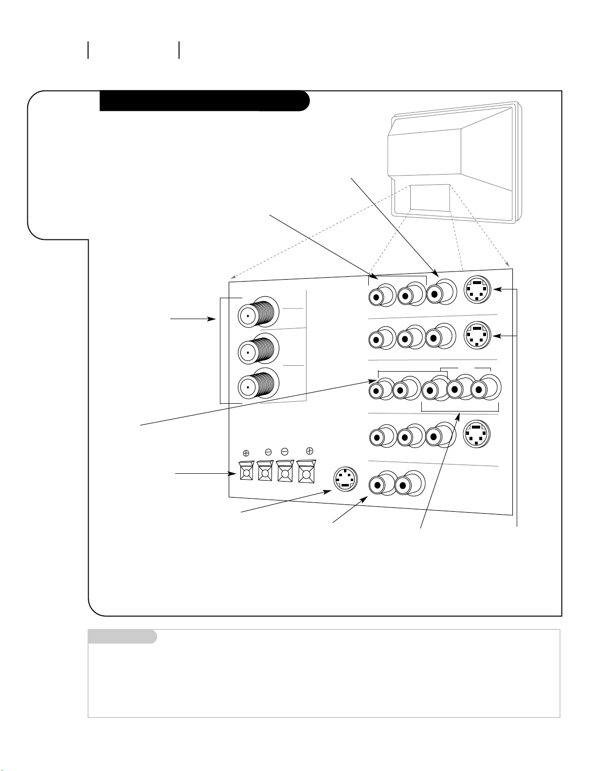
INSTALLATION GETTING STARTEDPAGE 4
Your jack-pack
and its
various uses.
Audio Video Jacks
3357-o
ANTENNA
CABLE 1
LOOP OUT
R- AUDIO- L/MONO
R- AUDIO- L/MONO
VIDEO 2
S-VIDEO 2
R- AUDIO- L/MONO VIDEO
S-VIDEO
R- AUDIO- L/MONO
VIDEO 1
S-VIDEO 1
VARIABLE OUT
R -AUDIO- L
RIGHT
LEFT
MONITOR OUT
ANTENNA
CABLE 2
INPUT
VIDEO 3/Y
R-Y B-Y
DVD
DATA
PORT
SURROUND SPEAKERS
RF Connectors:
Antenna/Cable 1,
Antenna/Cable 2,
and Loop Out
Used to connect
Antenna/cable to the
television, either
directly or through your
cable box.
Right/Left Audio
Used for stereo sound
from various types of
equipment.
Video 1/2/3
Connects the video
signals from various
types of equipment.
S-VIDEO 1/2
A feature available
with some very
high-end equipment
that provides even
better picture quality.
Y, R-Y, B-Y
Some top-of-the-line DVD
players use what is
called “component video,”
for extremely accurate
picture reproduction.
Refer to your DVD manual
for further information.
Variable Out
Used to connect
either an external
amplifier, or add a
sub-woofer to your
surround sound system.
Surround Speaker
Jacks Right/Left
Used to improve your
sound by connecting
surround-sound
speakers.
Data Port
Reserved for future
use.
Mini glossary
JACK A connection on the back of a TV, VCR, or any other A/V device. This includes the RF jacks and the Audio/Video jacks
that are color-coded.
SIGNAL Picture and sound traveling through cable, or in the air, to your television screen.
Video 3
Video 3 can be used
as a composite or
component input.
Page 5
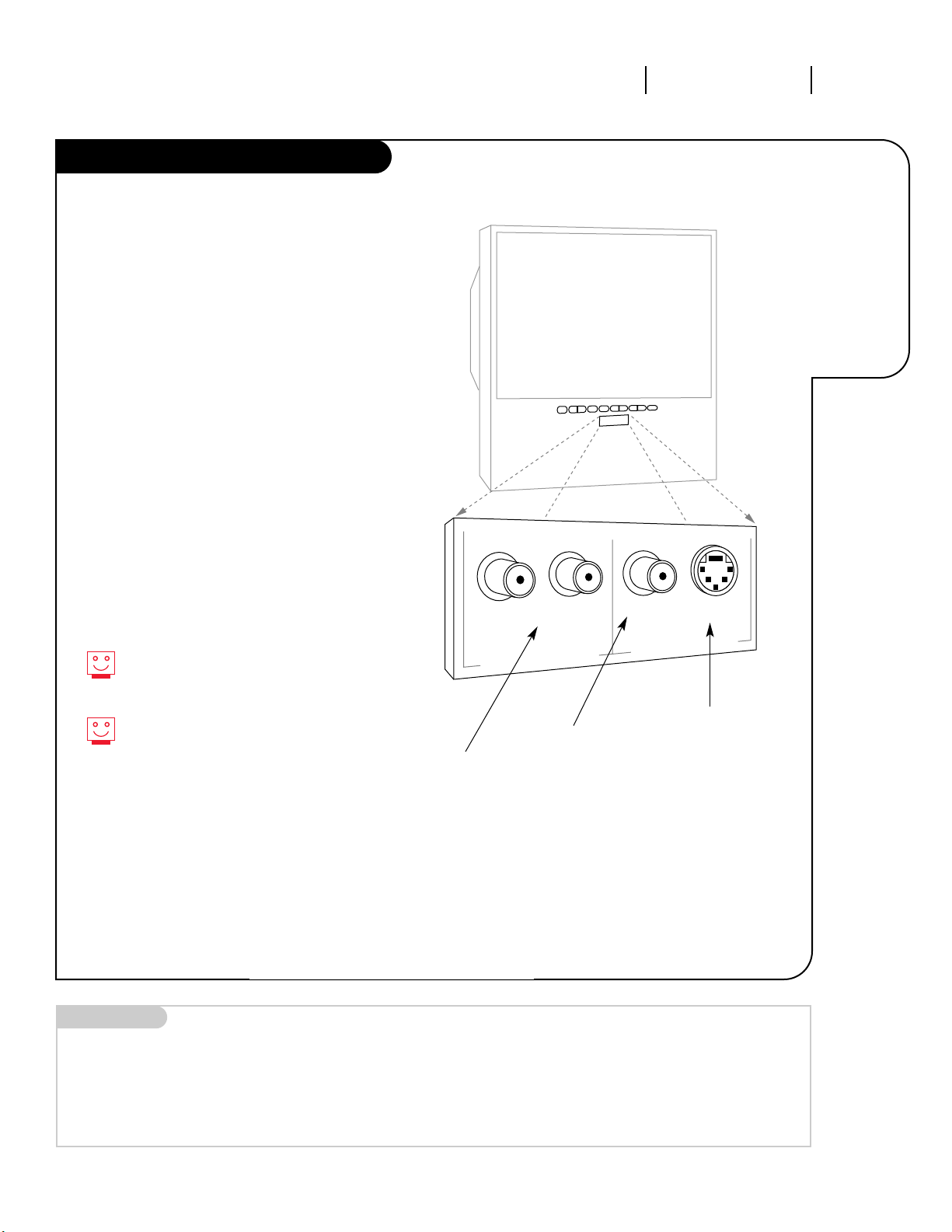
INSTALLATION GETTING STARTED PAGE 5
Hooking
up temporary
equipment
to your
Entertainment
Machine.
Front A/V Jacks
3357-o
S-Video
Video
Right
Left
video input
audio input
Front A/V Panel
There are four jacks on the front of
your Entertainment Machine that make
connecting Audio/Video devices like video
games and camcorders very simple.
The jacks are located behind a small door
below the buttons on the front panel.
The jacks are like those found in the jack
pack on the back of your Entertainment
Machine. Which means that any equipment
that connects to those types of jacks in
the rear jack pack, can also be connected
in front.
To use the front jacks as the signal source,
use the Source menu as described on page
22. They will be named “Frnt Video” and
“Frnt S-Video” in the Source menu, but if
you are using something else, and don’t
want to get confused, change the name
under the Source ID (see page 31).
Right/Left Audio
Used for stereo sound
from various types of
equipment.
Video
Connects the video
signals from any
piece of equipment.
S-VIDEO
A feature available
with some very
high-end equipment
that provides even
better picture quality.
When you choose Front Video
or Front S-Video, the audio is
automatically changed as well.
If you’re connecting a video game
unit, make sure to change the
picture settings with the Video
Preset option in the Video menu
(see page 36).
Mini glossary
A/V CABLES Audio/Video cables. Three cable connectors—Right audio (red), Left audio (white), and Video (yellow). A/V cables are used for stereo
playback of videocassettes and for higher quality picture and sound from other A/V devices.
A/V DEVICE Any device that produces video or sound (VCR, DVD, cable box, or television).
NOTE: The picture for the IQA36A46W will be different than the one shown. However, the front jacks
will be the same.
Model IQA32M46W does not have front jacks.
Page 6
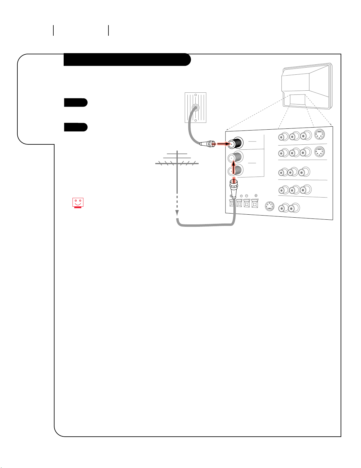
INSTALLATION STANDARDPAGE 6
Connecting
antenna/cable
to your
Entertainment
Machine.
Antenna/Direct Cable TV or Cable Box
3357-o
ANTENNA
CABLE 1
LOOP OUT
VARIABLE OUT
MONITOR OUT
ANTENNA
CABLE 2
INPUT
Cable TV
wall jack
Rf coaxial wire
(75ohm)
TV back
Locate the Antenna/Cable 1 jack
on the back of your Entertainment
Machine.
Connect the cable that runs from
the wall directly to this jack.
1
2
Hooking up to Antenna/Direct Cable
Hooking up to
Antenna/Direct Cable
If you receive antenna through a
wire that is several years old and
connects with two small prongs,
you will need to purchase a 300
Ohm adapter. It should be available from your local
electronics dealer.
RF coaxial wire
(75ohm)
Antenna
or
Page 7
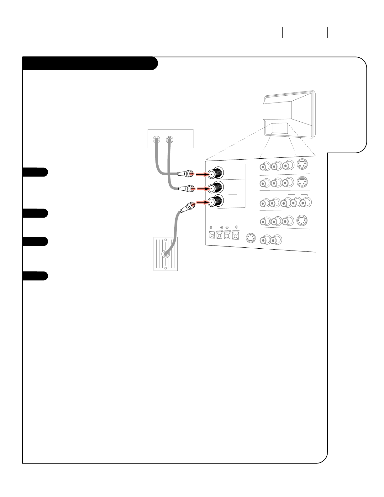
INSTALLATION STANDARD PAGE 7
Using a cable
box with
the Loop
Out function.
Cable Box
3357-o
Locate the Antenna/Cable 2 jack on
the back of your TV. Connect the
cable that runs from the wall directly to the jack. Now find the the
Loop Out jack.
Connect the cable from this jack to
the Input jack on the back of your
cable box.
Locate the Output jack on the back
of your cable box. Connect this to
the Antenna/Cable 1 jack on the
back of your TV.
To view the premium stations, set
the channel number on your cable
box to HBO, CINEMAX, SHOWTIME,
etc. Then go to the Source menu
and select the Antenna/Cable 1
source. See your Quick Setup Sheet,
included with this operating guide
for more information. See page 22
for information regarding Source
Menus.
To view the non premium channels
go to the Source Menu and select
Antenna/Cable 2. Then run Channel
Search to check for all available
channels and store them in its
memory.
This can be combined with any
other equipment you may want
to hook up. Hook cable directly into
the TV, then to the cable box. From
there, the cable box goes to the
next device, down the line, until
the last piece, which connects back
to the TV in the Antenna/Cable 1
jack.
1
2
3
4
Some cable services require the use of a
cable box to decode premium channels and
pay-per-view. Using the Loop Out to
Decoder option, and programming your
remote, you can connect your cable box so
that you only need your MBR Trakball
remote to control all the channels. By
connecting cable directly to your
Entertainment Machine, then running it out
to the cable box and back, you make the
cable box another source to choose from in
the Source menu (see page 22).
ANTENNA
CABLE 1
LOOP OUT
VARIABLE OUT
MONITOR OUT
ANTENNA
CABLE 2
INPUT
DVD
Cable TV
wall jack
Cable box
In
Out
Rf coaxial wire
(75ohm)
TV back
Page 8
ANTENNA
CABLE 1
LOOP OUT
VARIABLE OUT
MONITOR OUT
ANTENNA
CABLE 2
INPUT
DVD
TV back
In
Out
Audio
Video
3 4
VCR
Back AV panel
R- AUDIO- L
A/V cables
not included
with TV
Cable TV
wall jack
Round wire
(75ohm)
VIDEO 1
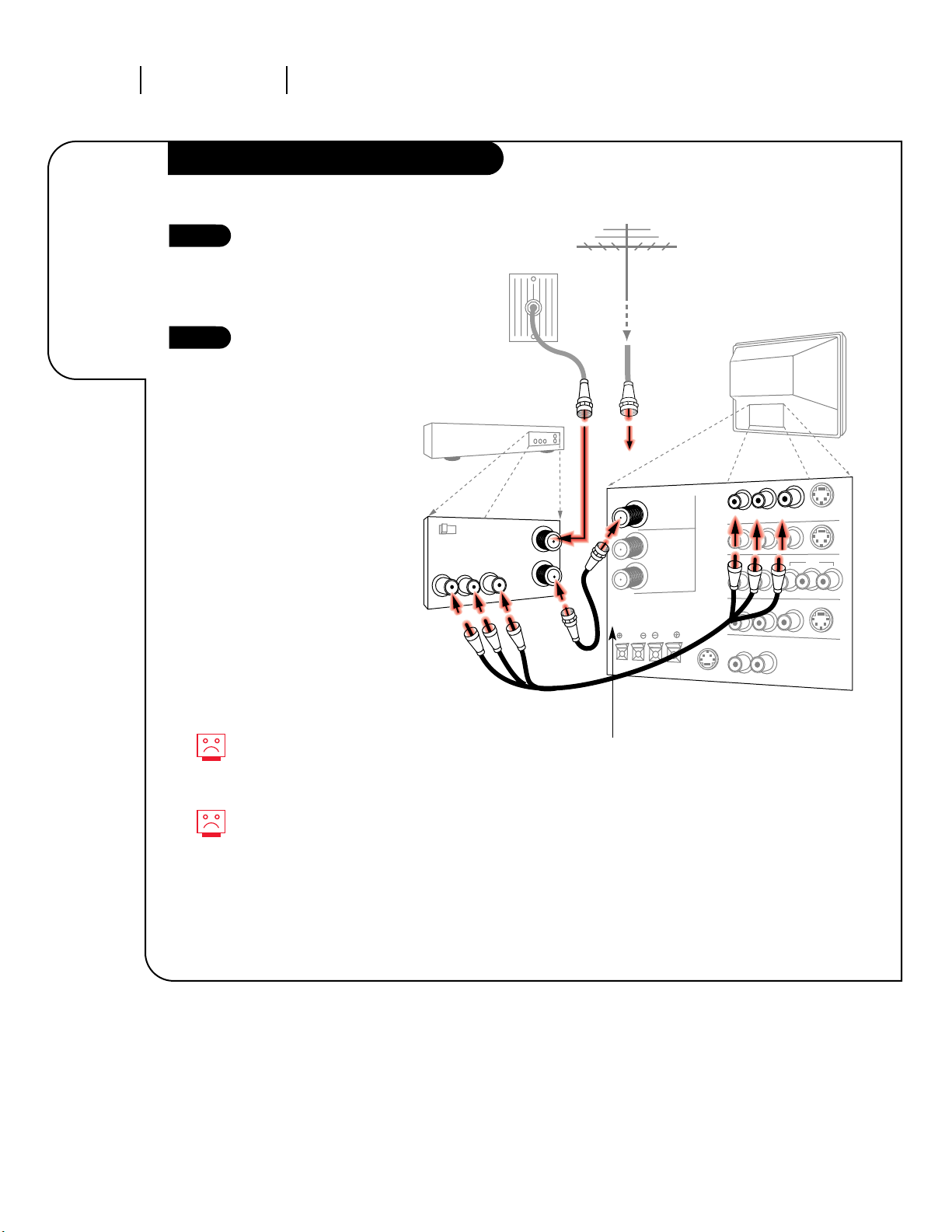
INSTALLATION STANDARDPAGE 8
Connecting a
VCR to your
Entertainment
Machine.
VCR
3357-o
Locate the RF or VHF/UHF/CATV
In jack on the back of your
VCR. Connect the Antenna or
cable wire coming from your
wall directly to this jack.
Find the composite video or
S-Video and audio jacks on
the back of your VCR, and
connect them following
the instructions provided with
your equipment.
You may connect either the
composite video or the SVideo cables to your
Entertainment Machine. Do
not connect both the composite and the S-Video.
1
2
To hear stereo sound from
your VCR, you will need to
connect A/V cables.
If you want to receive your
signals on Channel 3 or 4
from Antenna/Cable 1, locate
the Out to TV jack. Connect a
cable from the Out to TV jack
to the Antenna/Cable 1 jack
on the back of your
Entertainment Machine.
Optional (to receive
signal on channel 3 or 4).
Cable not included.
OR
RF coaxial wire
(75ohm)
Antenna
Page 9
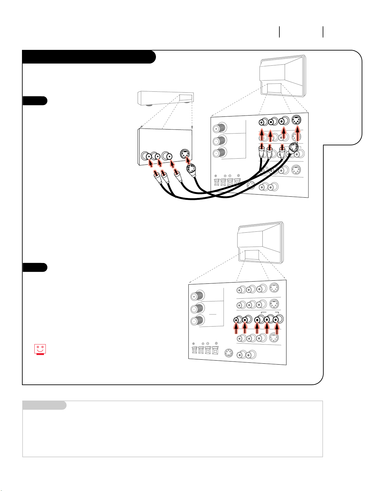
INSTALLATION STANDARD PAGE 9
Connecting a
DVD player or
S-VHS player
to your
Entertainment
Machine.
DVD Player
3357-o
Find the audio and composite
or S-Video jacks on the back of
your DVD Player and connect
them following the instructions
provided with your equipment.
You may connect either the
composite video or the S-Video
cables to your Entertainment
Machine. Do not connect both
the composite and the S-Video.
1
2
For several pieces of equipment, edit the
names under Source ID so you don’t forget which is which. See page 31.
Mini glossary
COMPONENT VIDEO Some video equipment uses three separate lines (Y, R-Y, B-Y) to more precisely reproduce images. Your manual will explain
how this relates to your equipment.
ANTENNA
CABLE 1
LOOP OUT
VARIABLE OUT
MONITOR OUT
ANTENNA
CABLE 2
INPUT
DVD
TV back
Audio
S-Video
DVD player
Back AV panel
R- AUDIO- L
S-VIDEO 1
A/V and S-Video
cables not included
with TV
L R
Video
OR
TV back
ANTENNA
CABLE 1
LOOP OUT
ANTENNA
CABLE 2
INPUT
DVD
R-AUDIO-L/ VIDEO 3/Y R-Y B-Y
Some high-end DVD players use a picture
reproduction system called “component
video.” If your DVD player has component
output, use the connectors marked “DVD”
on the jack panel. Please refer to your
DVD manual for proper installation.
Page 10
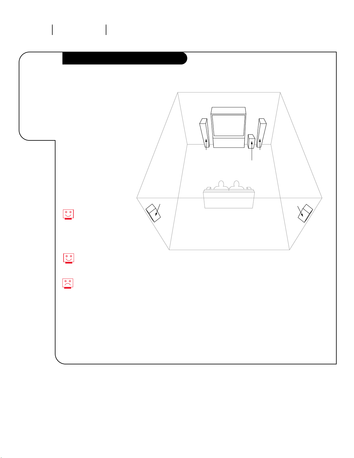
INSTALLATION AUDIOPAGE 10
General
help on
designing
your home
theater
set-up.
Room Set-ups for Home Theater
3357-o
sub-woofer
right
speaker
left
speaker
surround
sound
speaker
surround
sound
speaker
This is just a general room design.
Any number of set-ups are possible,
and some changes may be needed
to maximize your sound.
A left and right speaker on either
side of the Entertainment Machine
will create a phantom “center
channel,” making the dialog sound
as though it’s coming directly from
the Entertainment Machine. The rear
surround sound speakers provide
the majority of other sounds, like
those from special effects in movies.
Your sub-woofer generates ultra-low
frequency sound, for rumbling
low-end audio.
Sound is affected by
speaker placement, so
make sure nothing is in
front of the speakers, and
that they are aimed in
appropriate directions.
You have the option of
turning on or off the internal
speakers.
If your surround sound
system is on, but there’s no
sound from the speakers,
the program you’re watching
might not be broadcast in
surround sound.
NOTE: The picture for the
IQA36A46W will be different
than the one shown. However,
the setup will be the same.
Page 11
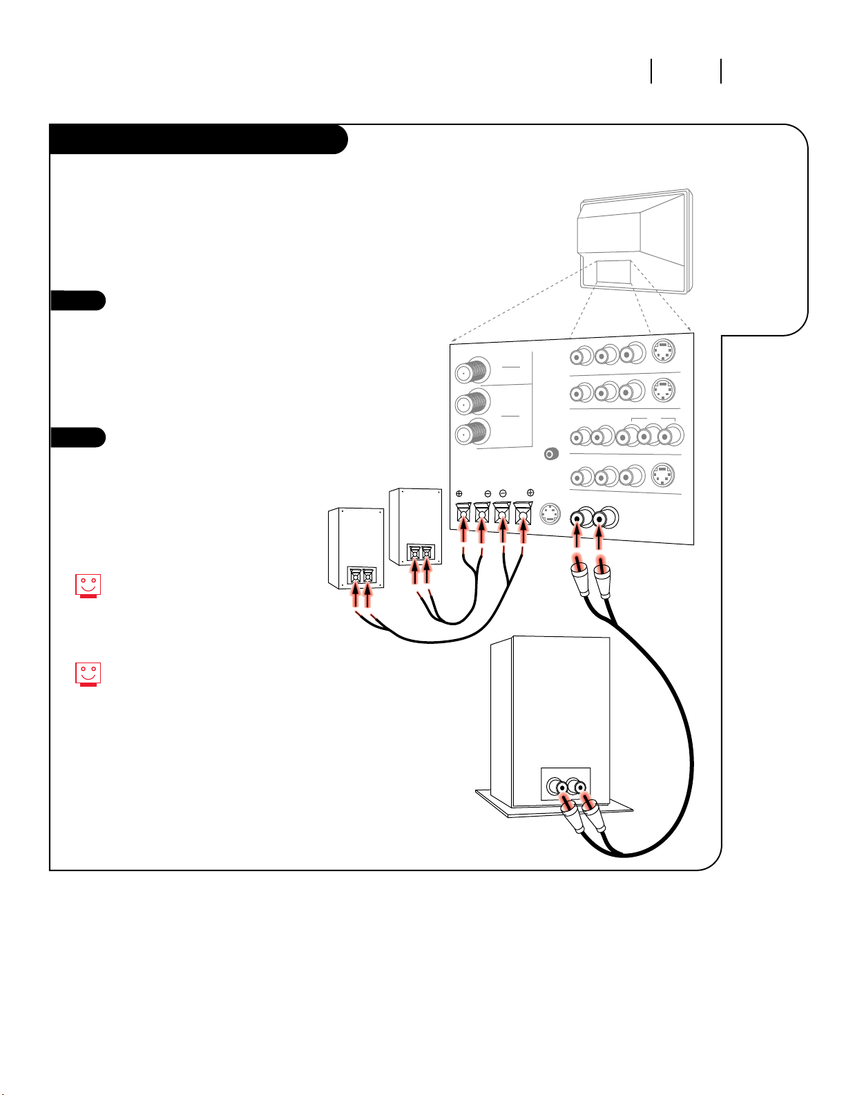
INSTALLATION AUDIO PAGE 11
Get the
best sound
possible
from your
Entertainment
Machine.
Audio Hookups
3357-o
ANTENNA
CABLE 1
LOOP OUT
VARIABLE OUT
MONITOR OUT
ANTENNA
CABLE 2
INPUT
DVD
TV back
SURROUND SPEAKERS
Right
Left
Surround Sound
Speakers
Audio cables
not included
with TV
Sub-woofer
Locate the Surround Speakers
jacks on the back of your
Entertainment Machine. Connect
the wires to the right or left
channel, depending on where the
speaker is located in your room.
The copper wire corresponds to
the Negative jack, and the silver
to the Positive.
Locate the jacks marked Variable
Out. These are for the sub-woofer.
Connect the sub-woofer’s cables,
according to their color (red is
the right channel, white the left)
to these jacks.
1
2
If you happen to have Mini-tower
speakers, these will be connected
to the back of your sub-woofer,
with the jack labeled Satellite
Speaker Output.
If you are using an external amplifier,
see page 12.
Before you begin plugging in your speakers,
it’s a good idea to put them in their
approximate places first. That way you
know how much wire you have or will need.
Page 12
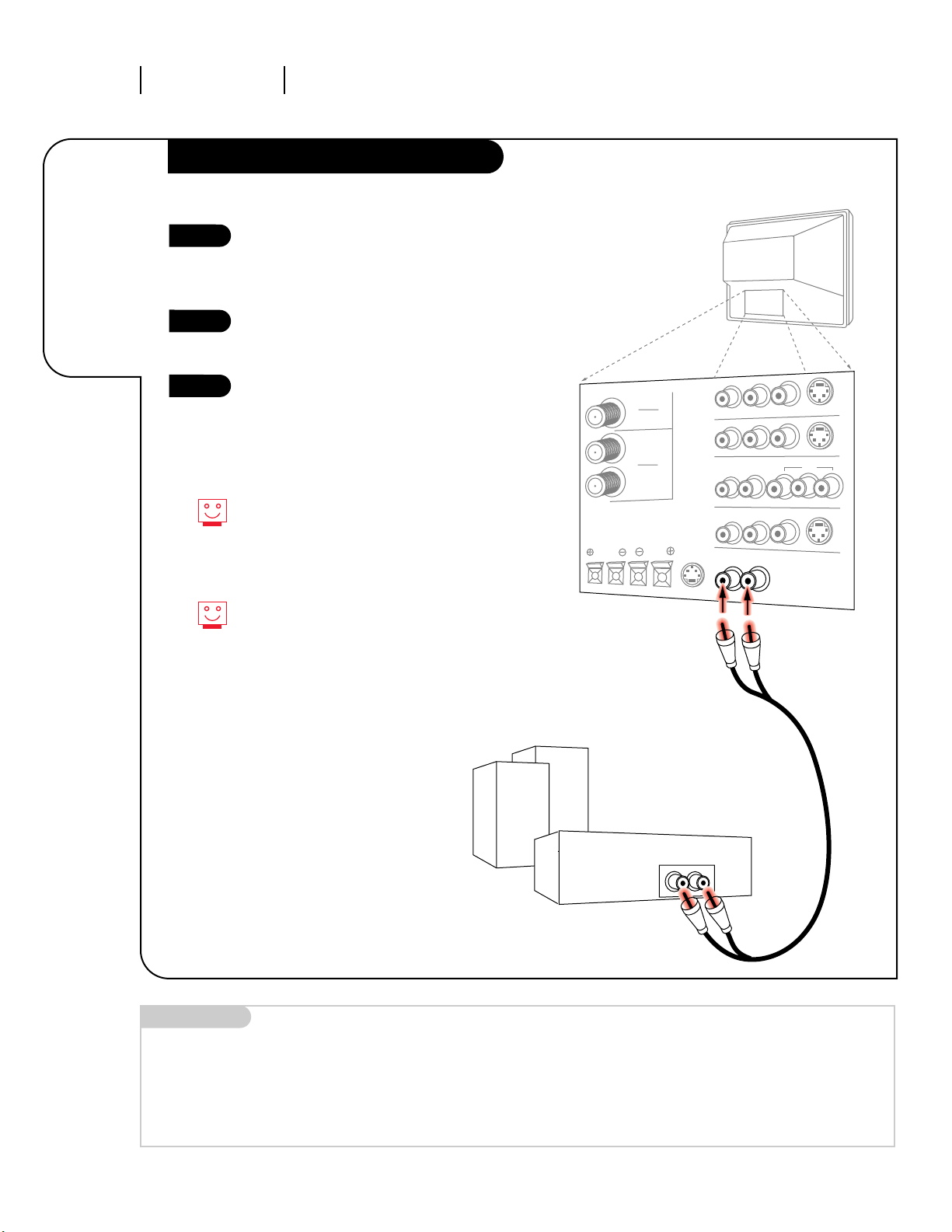
INSTALLATION AUDIOPAGE 12
Combine
your new
Entertainment
Machine with
your home
stereo system.
External Stereo
3357-o
ANTENNA
CABLE 1
LOOP OUT
VARIABLE OUT
MONITOR OUT
ANTENNA
CABLE 2
INPUT
DVD
TV back
SURROUND SPEAKERS
Audio cables
not included
with TV
External stereo amplifier
Locate the Variable Out jacks on
the back of your Entertainment
Machine and the Input jacks on
the back of your stereo’s amplifier.
Connect the two jacks, making
sure that the right and left
channels are placed correctly.
Set up your speakers through
your stereo, according to
those directions.
1
2
3
You can adjust the volume level
on your external stereo system
even if your remote is in TV mode.
See Amplifier Volume Override on
page 47.
You have the option of turning on
or off the internal speakers.
Mini glossary
AMPLIFIER An external machine that amplifies sound from a television, CD player, VCR, DVD or other A/V device.
Page 13
INSTALLATION GETTING STARTED PAGE 13
Have your
Entertainment
Machine
automatically
find and save
all the
channels
available to
you.
Quick Start
3357-o
v
o
l
u
m
e
c
h
a
n
n
e
l
mode
mute
flshbk
source
enter
menu
record
pause
1
2
3
4
5
6
7
8
0
9
surf
power
tv
vcr
cable
aux 1
aux 2
quit/
pip
rew
stop
ffwd
play
Use pages 6-12 to hook up your
Entertainment Machine. Plug in
your Entertainment Machine and
press the Power button on the
front panel. The Quick Start
screen will instantly appear, with
three steps you should follow if
you have not yet done so.
Remove the back of the remote
and put in three AAA batteries.
Make sure batteries are properly
installed (check the +/– signs).
Click ENTER on your remote to
continue the setup process.
Your choice will be to pick 1 or 2
(Antenna or Cable), depending on
the type of input signal you have.
You will then be prompted to press
3 on your number pad. Your
Entertainment Machine will now
search for all available channels,
and store them in its memory.
1
2
3
4
5
back of remote
3
5
4
The Quick Start menu appears
the first time you turn your
Entertainment Machine on, allowing
you to get this out of the way
before going on to other options.
The Quick Start option only works
when the current source for the
Main picture is Antenna/Cable 1.
Once you have programmed the
channels for Antenna/Cable 1 this
option will not appear in the menu
for another source.
Page 14
Quick Start
Ch. Search
Add/Del/Surf
Clock Set
Captions
Caption/Text
Language
Background
Projo Setup
Setup
123
INSTALLATION GETTING STARTEDPAGE 14
Find all your
available
channels from
any source.
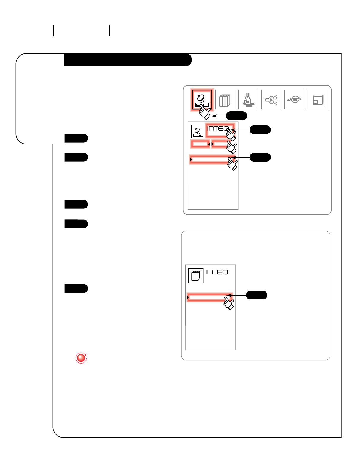
Channel Search
3357-o
Click on the Source Menu icon in
the Menu Display.
Click on Ant/Cable 2 to search
for available channels. This will
correspond either to the name on
the jack pack, or any name you
may have assigned it with the
Source ID option (see page 31).
Click on the words Inteq Source
and your Setup Menu will appear.
Select Ch. Search in the menu
by clicking on it once. Click it
again to enter the Channel Search
screen. You will be prompted
to determine if the signal is
coming from an antenna or cable.
Select one or the other by
pressing the correct number on
the Number Keypad.
Press 3 on your number keypad
to start the channel search for
the source you’ve picked. You
will automatically be returned to
regular viewing.
1
2
3
4
5
Source
Main PIP
Ant/Cable 1
Ant/Cable 2
Video 1
Video 2
S-video 1
S-Video 2
DVD/Video 3
Front Video
Frnt S-Video
123
1
3
4
2
When the screen tells you how
many channels it found, click
the Trakball twice to return quickly
to regular viewing.
This function allows you to set up the channel
selection on Antenna/Cable 2. Other sources,
such as VIDEO 1 and 2 won’t have channels
available to scan, and when they’re selected as
the source, the option won’t even appear in
the Setup menu.
Page 15
EXIT
Red
INSTALLATION GETTING STARTED PAGE 15
Adjust
the color
alignment
to make
your picture
the sharpest
it can be.
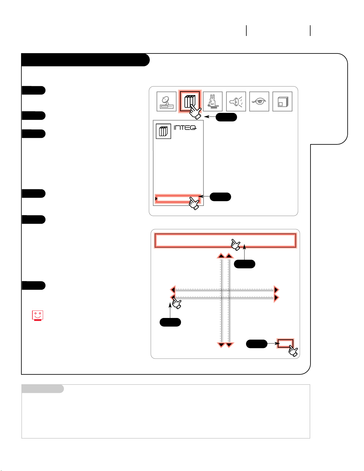
Projo Setup: Convergence
3357-o
Click on your Setup Menu icon in
the Menu Display at the top of
the screen.
Select Projo Setup on your screen
by clicking on it once.
Click again to enter the
Convergence screen. You will see
two intersecting lines. If the lines
are perfectly white, your colors
are fine. If you can see either
blue or red lines, then one or
both of those two colors needs to
be adjusted.
Click on the text across the top of
the screen to select which color
to adjust: Red or Blue.
Using the Up/Down and Right/Left
arrows on the remote, adjust the
colors so the lines match on the
screen and are completely white.
NOTE: Due to the small adjustments,
it may be easier to use the arrow
buttons on your remote, rather
than the Trakball.
Click EXIT to return to the Setup
Menu. Click on another option or
on the regular screen to return to
normal viewing.
1
2
3
4
5
6
If the lines never match up, no
matter what you try, give Zenith’s
Projection TV helpline a call at
1-800-365-1690.
123
Quick Start
Ch. Search
Add/Del/Surf
Clock Set
Captions
Caption/Text
Language
Background
Projo Setup
Setup
123
4
5
6
Mini glossary
CONVERGENCE This option lets you align the various colors in your picture so they look correct.
1
2/3
NOTE: This feature does not
apply to the model IQA36A46W.
Page 16
OPERATION TRAKBALL REMOTEPAGE 16
All the
buttons on
your remote,
and what
they do.
Button Functions on Your Remote
3357-o
v
o
l
u
m
e
c
h
a
n
n
e
l
mode
mute
flshbk
source
enter
menu
record
quit/
pause
pip
rew
stop
ffwd
play
1
2
3
4
5
6
7
8
0
9
surf
power
tv
vcr
cable
aux 1
aux 2
POWER
Turn your Entertainment Machine
or any other programmed equipment
on or off, depending on mode.
MODE LEFT/RIGHT
Adjust which mode your remote is
working in.
INDICATOR LIGHTS
Illuminate to show which mode
your remote is in.
FLSHBK
Return immediately to the last
channel viewed.
CHANNEL UP/DOWN
Scroll through your available
channels.
NUMBER KEYPAD
For direct channel selection and
programming functions.
ENTER
Push to accept menu choices or after
channel numbers for faster transfer.
PIP SNAPSHOT
Press to capture and freeze main
picture within large PIP frame. Press
a second time and receive PIP from
another channel or source. Press a
third time to remove PIP.
QUIT
Leaves programming menus and
clears screen of displays, and provides
audio swap.
RECORD, PAUSE
Control the functions on your VCR.
REW, FFWD, PLAY, STOP
Control the functions on your VCR.
MUTE
Press once for Soft Mute, again
for Full Mute, and a third time to
return to normal volume.
SURF
Use the regular channel selection or
your customized channel Surf lists.
VOLUME LEFT/RIGHT
Increases/decreases the sound level.
SOURCE
Push to switch between
available sources connected to
your Entertainment Machine.
MENU
Displays on-screen menus.
ARROW KEYS
Allows you to move through
on-screen menu choices.
TRAKBALL
Click and move the on-screen pointer.
Remote Control Part Number
MBR TRAKBALL: TRK 4000
Mini glossary
MODE The mode determines the type of device (TV, VCR, Cable, AUX) that the remote is controlling.
SURF Access a customized group of channels by pushing the surf button on the remote.
Page 17
OPERATION TRAKBALL REMOTE PAGE 17
Learn the
easiest way
to get at
every option
on your
Entertainment
Machine!
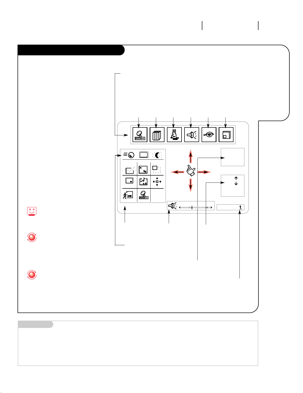
Using Your Trakball Remote
3357-o
Make sure your Entertainment Machine is
on. Just click the Trakball by pressing
gently with your thumb, and a hand-shaped
pointer will appear.
You can now move the pointer anywhere
on the screen by rolling the Trakball with
your thumb. As you move it from side to
side, top to bottom, different menus will
appear on-screen.
You can use and adjust any of these
options by rolling the pointer so the index
finger on the screen is touching the icon
for the menu or option you want. Click the
Trakball again, and the option or menu
is selected.
When you’re finished and want to return to
normal viewing, either wait a few seconds
and the pointer will disappear, or move the
pointer so that it isn’t touching any icons
or menus, and click again.
Ch 07 - NBC
4:55
Mono
Ch.
Ch.
All Chan
Flashback
Surf 1
Volume
123
PIP
FREEZ
PIP
CHAN
CC
Menu Display, which lets you access the Source menu (see page 22),
the Setup menu (see pages 23-27), the Features menu (see pages 28-34),
the Audio menu (see page 35), the Video menu (see page 36), and the
Picture-in-picture menu (see page 39).
Source
Menu
Setup
Menu
Features
Menu
Audio
Menu
Video
Menu
PIP
Menu
Channel/Time Display
(see page 19).
Picture-in-Picture/
Features Menu
(see pages 37-39).
Volume
Display
(see page 19).
Channel
Selection
Display
(see page 19).
Surfing Display
(see page 32).
When your pointer touches certain
on-screen icons, a small text window
appears to the right of the pointer,
telling what the icon represents.
The point-and-click interface does
everything buttons do, just like
your computer. Click words
on-screen instead of pressing the
button. Or click on items instead
of scrolling with the arrow keys.
Trakball shortcut: To quickly exit
any menu screen, click on the
main screen — outside the borders of the menus display.
Mini glossary
POINTER The image of the hand that appears on-screen and points to the option you want to work with.
ICON A small picture on your screen that represents a function or menu item.
Trakball Speed, Closed
Captions, and Sleep Timer
(see next page).
Page 18
OPERATION TRAKBALL REMOTEPAGE 18
Learn the
easiest way
to get at
every option
on your
Entertainment
Machine!
Using Your Trakball Remote, cont’d
3357-o
When adjusting options that are on
a sliding scale, such as volume,
you don’t have to increase or
decrease them one step at a time.
Just click anywhere on the
spectrum, and the setting will
jump to that point. From there
you can fine tune the levels by
clicking on the small left- and
right-pointing arrows (decrease
and increase, respectively),
moving the levels in small steps.
Just about everywhere you see text
or an icon on your screen, you
can probably click there to make
something happen. For example,
once you have one of the items
from the Menu Display on your
screen, such as the Setup Menu,
you can just click on the icon in
the upper left of that menu to
cycle through the other menus.
You can adjust the speed your
Trakball moves across the screen
by clicking on the small
Trakball icon at the top of the
PIP/Features Menu. The higher
the speed you set, the more sensitive the Trakball will be to your
movements.
Click on this icon to view the
Captions Menu. See page 25.
To view the Sleep Timer menu,
click on this icon. See page 28.
Volume
PIP
FREEZ
PIP
CHAN
CC
Quick Start
Ch. Search
Add/Del/Surf
Clock Set
Captions
Caption/Text
Language
Background
Projo Setup
Setup
123
Timer Setup
Ch. Labels
Source ID
Surf ID
Parental Ctl
Auto Demo
Features
These 9 buttons adjust
your Picture-in-Picture
feature. See pages 37-39.
1
2
3
4
5
1
4 5
1
2
3
Page 19

OPERATION TV FUNDAMENTALS PAGE 19
Introducing
you to the
basics of your
Entertainment
Machine.
Basic TV Operation
3357-o
To watch TV on antenna, cable, a VCR, DVD or any other piece of equipment,
you have to make sure you’ve set your Entertainment Machine to the
correct source. Check page 22 to see how to use the Source menu. The
current source is displayed on the top line of the Channel/Time display.
It will show a channel number if the source is Ant/Cable 1 or 2, and
read the name of the source (such as VCR) for anything else.
Click the Ch. Up/Ch. Down text to move through the channels, or use
the CHANNEL UP/DOWN arrows on your remote to move through your
channel list.
Skip to a specific channel by clicking on the ALL CH text and then
double-clicking on a number, or by entering the number of the channel
on the NUMBER KEYPAD on your remote.
To instantly return to the last channel you were watching, click FLSHBK,
or press the FLSHBK button on your remote.
This is while the source is set to Ant/Cable 1 or 2. For any other
source, such as a VCR or DVD player, the Main Picture channel
changing will be controlled by that equipment.
Click on any part of the Volume bar to jump to that sound level, or click
on the small arrows to move in small increments. You can also use the
VOLUME RIGHT/LEFT buttons on your remote to adjust the volume level.
Clicking once on the Speaker Icon in the Volume display will put your
Entertainment Machine into SOFT MUTE. Clicking again will MUTE it
completely, and once more will bring the sound back. Or, using the
buttons on your remote, press MUTE once to reduce the sound level to
the SOFT MUTE level. Press once more to completely MUTE the sound.
Press again to return to full sound level.
Source
Channel Changing
Audio
Mini glossary
SOURCE The term for the equipment that provides audio and video information to your Entertainment Machine. VCR, DVD players, or
Cable Boxes are examples of sources.
Ch 07 - NBC
4:55
Mono
Channel or Video
(Indicates Source)
Time
Audio Mode
Cycle up or down
through the channels
Choose a specific
channel
Return to the last
channel viewed
Ch.
Ch.
All Chan
Flashback
Volume
Click here to
mute
Click here to
raise or lower
the volume
Page 20

OPERATION MENUSPAGE 20
Descriptions
of all the
menus on your
Entertainment
Machine.
On-Screen Menus
3357-o
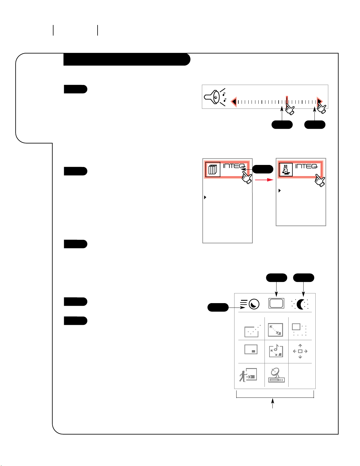
SOURCE MENU Choose from the available sources for both the main picture and PIP.
SETUP MENU Adjust the basic characteristics of your Entertainment Machine. 13-15,
Quick Start Automatically finds and stores active channels to flip through using Channel
Up/Down.
Channel Search Finds and stores active channels.
Add/Del/Surf Manually pick and choose which active channels will appear when flipping
through using Channel Up/Down.
Clock Set Set the time yourself, or program your clock to automatically
detect the time, and to adjust to Daylight Savings when you
program in your time zone.
Captions Turn closed captioning on, off, or set it to come on automatically
when the Entertainment Machine is muted.
Captions/Text Choose the captioning or text method for your Entertainment
Machine.
Language Pick the language you want your on-screen menus to appear in.
Background Turns the background for on-screen menus transparent or opaque.
Projo Setup Allows you to adjust the color convergence of your
Entertainment Machine.
FEATURES Go beyond basics and customize your Entertainment
MENU Machine’s functions.
Timer Setup Program a time for your Entertainment Machine to turn itself on or off, or to
turn itself off after a certain amount of time.
Channel Labels Label your channels with their network names (ABC, CBS, HBO, etc.).
Source ID Customize the names of your sources by either selecting a label or making
your own.
Surf ID Design a custom channel surf selection for up to four people, and put their
names on them.
22
23-27
13
14
23
24
25
25
26
27
15
28-34
28-29
30
31
32
Using the Menu button on your remote or by using the Trakball, you can access
all the menus below.
Menu Name Go to page
Page 21

OPERATION MENUS PAGE 21
Descriptions
of all the
menus on your
Entertainment
Machine.
On-Screen Menus Overview, cont’d
3357-o
Parental Control Allows parents to block any channel for up to 99 hours, with the use
of a password.
Auto Demo Your Entertainment Machine will show you what it’s capable of
by running through many of its options and menus automatically.
AUDIO MENU Customize the sound to suit your room and your taste. Your options
are: Bass, Treble, Balance, Audio Mode, SoundRite, Front Surround,
Rear Surround, BBE Audio, Speakers.
VIDEO MENU Adjust your picture for any viewing situation. Your options are:
Contrast, Brightness, Color, Tint, Sharpness, Color Temp, Video Filter,
Skin Tone, Video Preset.
PIP MENU Control the size and appearance of the PIP inset. Your options are:
Contrast, Tint, Size.
Using the Trakball, you have even more options. Click once and
move the pointer around the screen to access these menus
(for more information, see pages 17 and 19).
Menu Display Access any of the on-screen menus by clicking on an icon from
this list.
Channel/ Shows the current time, channel, video and audio source, and the
Time Display Surf status.
Volume Display Shows the current sound level.
PIP/Features Controls aspects of PIP inset and access to Trakball speed, Sleep timer
Menu and closed captioning.
33
34
35
36
38-39
17-19
17
19
19
18, 38
Menu Name (cont’d) Go to page
Page 22

Source
Main PIP
Ant/Cable 1
Ant/Cable 2
Video 1
Video 2
S-video 1
S-Video 2
DVD/Video 3
Front Video
Frnt S-Video
123
OPERATION SOURCE MENUPAGE 22
Choose
the sources
for your main
picture
and PIP.
Source Menu
3357-o
Click on your Source Menu icon in
the Menu display.
Click on the word Main or PIP to
set the signal source for that
item. “Main” is for your regular
picture signal, and “PIP” is for
the Picture-In-Picture feature.
Click on the source where your
signal is coming from. This listing
will correspond to the jack names
on the front and back of your
Entertainment Machine, unless
you changed the names under the
Source ID option. To change the
name of these labels see page 31.
NOTE: You cannot have the Main
Source fron Ant/Cable 1 and the
PIP source in Ant/Cable 2 or vice
versa. PIP must be the same
Ant/Cable source as the main or
one of the video sources.
Click on the regular screen to
return to normal viewing.
1
2
3
4
1
2
3
4
Mini glossary
SOURCE The term for the equipment that provides audio and video information to your Entertainment Machine. VCR, DVD players, or
Cable Boxes are examples of sources.
This menu is where you switch input source
devices so you can watch your antenna, cable TV,
VCR, DVD, or anything else that you have hooked
up to your Entertainment Machine. Regular
antenna or cable will come through either
Antenna/Cable 1 or Antenna/Cable 2, depending
on how you set up your system. All other
devices will correspond to the names of the
jacks that they’re connected to.
Repeat these steps to set the
signal source for your PIP feature.
Page 23

OPERATION MENUS SETUP MENU PAGE 23
Create your
own channel
selection
for cooler
surfing.
Add/Del/Surf
3357-o
Mini glossary
ADD This function lets you add new channels to the list that you’ll scroll through when using your remote.
DELETE This function lets you remove channels that you don’t watch from the list you’ll scroll through.
SURF This function creates a customized list of your favorite channels. You can access this group of channels by
pushing the surf button on the remote or by clicking on the Surfing display (see page 17).
Instead of “Surf 1” or “Surf 2,”
customize the name of your program
listings. See Surf ID on page 32.
Click on the Setup Menu in your Menu
Display.
Click on Add/Del/Surf in the menu.
Click on it again and your screen will
be replaced by a large blue one with a
full channel listing.
Click on the channel number you wish
to modify (add/delete to your channel
list). Click on channel number again to
add or delete from your listing.
Click on the No Surfing text to change
to a Surf channel listing (Surf 1, Surf
2, etc.).
Click on the channel number you wish
to modify (add/surf to your channel
list). Click on the channel number
again to add it to your Surf listing.
Note: Dark grey channels (deleted
channels) cannot be changed.
Cycle through your other Surf modes
(Surf 2, Surf 3, etc.) and repeat steps
4 and 5 to set up additional Surf
channel listings.
Click on EXIT to return to the Setup
Menu. Click on another option or click
on the regular screen to return to
normal viewing.
1
2
3
4
5
6
Deleted channels will appear in a
gray color, while Added ones will be
in white.
Surfed channels will have a pink
surfer icon next to them.
123
Quick Start
Ch. Search
Add/Del/Surf
Clock Set
Captions
Caption/Text
Language
Background
Projo Setup
Setup
123
1
6
11
16
21
26
31
36
41
46
51
56
61
2
7
12
17
22
27
32
37
42
47
52
57
62
3
8
13
18
23
28
33
38
43
48
53
58
63
4
9
14
19
24
29
34
39
44
49
54
59
64
5
10
15
20
25
30
35
40
45
50
55
60
65
More Channels
Ch 32
Added
No Surfing
EXIT
1
3
4/6
5
7
2
7
Page 24

OPERATION MENUS SETUP MENU
PAGE 24
Set the clock
or have it
done for you,
automatically.
REALLY
impress your
friends.
Clock Set
3357-o
Embedded in the PBS broadcast
signal is the information for the
correct time and date. Your
Entertainment Machine will read
that information and automatically
display the right time.
If you follow these steps and your
time is still one hour off, check your
Time Zone and Daylight Savings
Time within your Entertainment
Machine to make sure they are
properly set.
Click on your Setup Menu icon in
the Menu Display.
Click on Clock Set in the menu. Click
it again to reach the Clock menu.
Click on Clock Mode in the menu.
Click again and a display will appear
at the bottom of your screen.
Choose either Auto or Manual for
clock mode. Manual will let you set
the time yourself while Auto will set
it for you while your Entertainment
Machine is off.
Manual: Choose Manual, then return
to the Clock menu by clicking on
Exit. Click on Time Set twice, and
you will reach a display where you
can set the time by clicking on the
HH:MM AM/PM display to cycle
through the times.
or
Auto: Choose Auto, then return to
the Clock menu. Click twice on PBS
Channel, then use the NUMBER
Keypad to enter the PBS Channel.
Your current channel will change to
that station.
Turn off your Entertainment
Machine for ten seconds to activate
the correct time.
1
2
3
4
5
6
7
123
Quick Start
Ch. Search
Add/Del/Surf
Clock Set
Captions
Caption/Text
Language
Background
Projo Setup
Setup
123
Clock Mode
Manual
Auto
Clock Mode
Time Set
Clock
XII
III
VI
IX
Clock Mode
Time Set
Clock
XII
III
VI
IX
Clock Mode
Manual
Auto
Clock Mode
PBS Channel
Time Zone
Day. Saving
Clock
XII
III
VI
IX
Clock Mode
PBS Channel
Time Zone
Day. Saving
Clock
XII
III
VI
IX
1
2
3 5
3
4
6
Manual Mode
Auto Mode
4
Page 25

OPERATION MENUS SETUP MENU
PAGE 25
Turn closed
captioning
or text on,
off, or have
it appear
automatically.
Captions and Caption/Text
3357-o
123
Quick Start
Ch. Search
Add/Del/Surf
Clock Set
Captions
Caption/Text
Language
Background
Projo Setup
Setup
123
Click on your Setup Menu icon in
the menu display.
Select Captions in the menu by
clicking on it. Click on it again
and a display will appear at the
bottom of your screen.
Choose whether you want the
captions Off, On or Caption When
Muted.
Click on EXIT to return to the
Setup Menu.
Select Caption/Text from the menu
by clicking on it. Click again to
reach the Caption/Text display.
Choose which type of captioning
or text you want by clicking on
that item.
Click EXIT to return to the Setup
menu. Click on the regular screen
to return to normal viewing.
1
2
3
4
5
6
7
Choose Caption 1 to view
traditional Closed Captioning.
With the Trakball, you can also go
to the PIP/Features menu and
click on “CC” to enter the Captions
menu. See page 18.
Not all programs have captions.
Mini glossary
CAPTIONS A form of subtitling that writes out the dialog for your program.
TEXT Arbitrary text not related to the program.
CAPTION WHEN MUTED Sets captioning to come on automatically when your volume is soft muted or muted.
Captions
Off
On
Caption When Muted
EXIT
Caption/Text
Caption 1
Caption 2
Caption 3
Caption 4
Text 1
Text 2
Text 3
Text 4
EXIT
123
Quick Start
Ch. Search
Add/Del/Surf
Clock Set
Captions
Caption/Text
Language
Background
Projo Setup
Setup
123
1
2
5
3
4
7
6
Page 26

3357-o
OPERATION MENUS SETUP MENUPAGE 26
Language Menu
Choose what
language your
on-screen
menus
appear in.
Click on your Setup Menu icon in
the menu display.
Select Language by clicking on it.
Click again and the Language
Menu will appear at the bottom
of your screen.
Choose the language you want by
clicking on English, Spanish, or
French.
Click on EXIT to return to the
Setup Menu.
Click on the regular screen to
return to normal viewing.
1
2
3
4
5
123
Quick Start
Ch. Search
Add/Del/Surf
Clock Set
Captions
Caption/Text
Language
Background
Projo Setup
Setup
123
Language
English
Español
Français
EXIT
1
5
2
3
4
Page 27

3357-o
OPERATION MENUS SETUP MENU PAGE 27
Customize
the look
of your
on-screen
menus.
Background
Click on your Setup Menu icon in
the menu display.
Select Background by clicking on
it in the menu.
Choose whether you want an
opaque background Off or On by
clicking on your choice.
Click on EXIT to return to the
Setup menu.
Click on another option to alter,
or on the regular screen again to
return to normal viewing.
Turning your Background On makes
reading the menus easier.
1
2
3
4
5
123
Quick Start
Ch. Search
Add/Del/Surf
Clock Set
Captions
Caption/Text
Language
Background
Projo Setup
Setup
123
Background
Off
On
EXIT
1
5
2
3
4
Page 28

3357-o
OPERATION MENUS FEATURES MENU
PAGE 28
Have your
Entertainment
Machine go
to sleep
any time.
Timer Setup: Sleep Timer
The sleep timer can also be
accessed by the moon and stars
icon on the top of the
PIP/Features menu. See page 18.
As the Good Night Display counts
down the final 60 seconds, the
audio and video of the
Entertainment Machine “dim” for
a soft discreet turn-off.
Click on your Features Menu icon
in the menu display.
Select Timer Setup in the menu
by clicking on it. Click on it again
and the Timer Menu will appear,
replacing the features Menu.
Click on Sleep Timer in the menu
to highlight the feature. Click it
again to specify an amount of
time before your Entertainment
Machine turns itself off.
You can increase or decrease
the amount of time in increments
up to four hours by clicking on
the time display, or using the
Left/Right arrows on the bottom
of your remote.
Note: To turn the feature off, you
must cycle through the times
until Off appears.
Click on EXIT to return to the
Timer Menu.
1
2
3
4
5
123
Timer Setup
Ch. Labels
Source ID
Surf ID
Parental Ctl
Auto Demo
Features
Sleep Timer
On Time
Off Time
On/Off Timer
Timer
Sleep Timer
Off
EXIT
1
2
3
4
5
Page 29

On Time
00:00 AM
EXIT
On/Off Timer
Off
On
EXIT
Off Time
00:00 AM
EXIT
3357-o
OPERATION MENUS FEATURES MENU PAGE 29
Have your
Entertainment
Machine wake
up and go
to sleep
any time.
Timer Setup: On/Off Timer
To activate the On/Off Timer, you
must set an Off Time. The On time
is optional.
5
6
7
8
Click on your Features Menu icon
in the menu display.
Select Timer Setup in the menu
by clicking on it. The Timer Menu
will appear, replacing the
Features menu.
Click on On Time first to highlight
the feature and a second time to
set the time your Entertainment
Machine turns itself on. A display
will appear at the bottom of
your screen. The number appears
in the form (HH:MM AM). Select
the amount time by entering a
number using your NUMBER PAD
on your remote. Select AM or PM
by pushing the FLSHBK button
repeatedly on the remote, or
simply click on AM/PM.
Click on EXIT to return to the
Timer Menu.
Click on Off Time to highlight the
feature and a second time to set
the time your Entertainment
Machine will turn itself off. Repeat
step number 3 to enter an Off time.
Click on EXIT to return to the
Timer Menu.
Click on On/Off Timer to decide
if your Entertainment Machine
will observe the times you
entered above. Select ON and it
will shut off and turn on at the
specified times.
Click on EXIT to return to the
Timer Menu.
1
2
3
4
123
Timer Setup
Ch. Labels
Source ID
Surf ID
Parental Ctl
Auto Demo
Features
Sleep Timer
On Time
Off Time
On/Off Timer
Timer
1
3
2
3
4
7 8
5 6
Page 30

----
ACTS
BCC
CBC
CNN
CTV
ESPN
FLIX
FSN
HBO
NONE
AD&E
BET
CBN
CDM
DIS
ESP2
FNN
FX
HBO2
A&E
ADC
BRAV
CBS
CSPE
DISC
ET
FOOD
GALA
HBO3
ABC
AMC
CA
CATV
CSP2
E!
EWTN
FOX
GOLF
HC
ACTN
AT
CAAT
CNBC
CTN
ENC
FAM
F&V
H&G
HIST
More Labels
Ch 32
AMC
EXIT
EDIT
Ch
Ch
OPERATION MENUS FEATURES MENUPAGE 30
Choose
preset labels
for channels
or create
your own.
Channel Labels
3357-o
Click on your Features icon in the
menu display.
Select Ch. Labels by clicking on
it. Click again and a blue screen
will fill with a list of possible
channel labels. The current channel
will appear in the upper-right
corner inset.
Choose a channel to label with
the Channel Up/Down display on
the right side of your screen.
Choose a label for the channel by
clicking on it.
NOTE: The (----) label indicates
that your TV will accept the
original, broadcast label if sent
by the broadcaster, and (None)
will block all labeling.
To edit any of the labels, click on
the label again or select EDIT at
the right side of the screen.
Another screen will appear with
the alphabet. Click on any of up
to four letters, then click EXIT to
return to the Channel Label screen.
Click EXIT to accept the label and
return to the Features menu. Click
on the regular screen to return to
normal viewing.
1
2
3
4
5
6
123
Timer Setup
Ch. Labels
Source ID
Surf ID
Parental Ctl
Auto Demo
Features
1
4/5
3
5
6
2
EXIT
5
ABC _
_ABCDEFGHI JKLMNO
PQR STUVWXYZ 0 12 3 4
567 89,. /&#+ ! ?* ñÉ
5
If you watch cable with a cable
box and have your channel set to
3 or 4, you should set the label
to None.
Page 31

Source
Ant/Cable 1
Ant/Cable 2
Video 1
Video 2
S-Video 1
S-Video 2
Video 3
Front Video
Frnt S-Video
Label
ANTENNA
–––
–––
–––
–––
–––
–––
–––
–––
EDIT
EXIT
OPERATION MENUS FEATURES MENU PAGE 31
Name
the sources
for the
Entertainment
Machine with
Source ID.
Source ID
3357-o
Click on your Features Menu icon
in the menu display.
Select Source ID by clicking on
it. Click it again to enter the
Source ID menu. Your screen will
be replaced by a blue one that
lists all the sources and their
current labels.
Select the Source name you want
by clicking on it. Click repeatedly
on the label to cycle through all
the available names.
Note: The (–––) label indicates
that your source name will be the
default name shown in the source
column.
If you don’t see a name that you
want, click on EDIT to enter the
label edit screen. A customizable
alphabet feature will appear. To
customize the name, click on the
letters of the name you want (up
to 10 characters). Click on EXIT
to return to the Source ID screen.
When you’re done, click on EXIT
to return to the Features menu.
Click on another selection, or on
the regular screen to return to
normal viewing.
1
2
3
4
5
6
Source IDs can be edited
and re-edited every time you
rearrange your equipment.
Make sure to keep track!
Sources can be disabled by choosing
that option under label so they
will not appear in the source menu
or when pressing the source button.
If you want to return a label to
the default name, edit the name
using all spaces in place of letters.
123
Timer Setup
Ch. Labels
Source ID
Surf ID
Parental Ctl
Auto Demo
Features
2
1
5
3
4
The titles under Source
will correspond to the
jack labels on the back
of your Entertainment
Machine.
The titles under Label will change
as you click on the source name.
If the dashes are chosen, the
source name will be the default
name as it appears above (under
the Source).
EXIT
4
_ANTENNA__
_ABCDEFGHI JKLMNO
PQR STUVWXYZ 0 12 3 4
567 89,. /&#+ ! ?* ñÉ
4
Page 32
OPERATION MENUS FEATURES MENUPAGE 32
Customize the
names of your
surf channel
lists for up to
four people.
.
Surf ID
3357-o
Click on your Features Menu icon
in the menu display.
Click on the Surf ID item in the
menu. Click again and your screen
will be replaced by a blue one,
showing all your available surf lists.
Highlight the Surf channel list you
want to edit by clicking on it.
Click repeatedly on the label to
cycle through the available names.
Note: Be sure to indicate the specific
channel list you wish to edit. For
example, Surf 2 should be selected
if Surf 1 has already been edited.
Click on EDIT to enter the label edit
screen. An alphabet, including
some symbols will appear. Spell out
the name you want by clicking on
one letter after the other (up to
10 characters). Click on EXIT to
return to the Surf ID screen.
Click on another Surf channel list
to continue editing, or click on
EXIT to return to the Features
Menu. To program Surf 2, 3, and 4,
click on those specific options and
repeat steps one through four
above. See page 23 for additional
information.
Click on another option, or click
on the regular screen to return to
normal viewing.
If you want to return a label to the
default name, edit the name using
all spaces in place of letters.
Customized surf channel lists can
be disabled by choosing that option
under label so they will not appear
in the surfing display when pressing
the surf button.
1
2
3
4
5
6
Surf
Surf 1
Surf 2
Surf 3
Surf 4
Label
SURF 1
–––
–––
–––
EDIT
EXIT
123
Timer Setup
Ch. Labels
Source ID
Surf ID
Parental Ctl
Auto Demo
Features
2
1
5
3
4
EXIT
4
DAD _ _ _ _
_ABCDEFGHI JKLMNO
PQR STUVWXYZ 0 12 3 4
567 89,. /&#+ ! ?* ñÉ
4
The titles under Label will change
as you click on the Surf name. If
the dashes are chosen, the Surf
name will be the default name as
it appears above (under the word
Surf).
Page 33

OPERATION MENUS FEATURES MENU PAGE 33
Determine
the channels
and video
your kids
can access.
Parental Control
3357-o
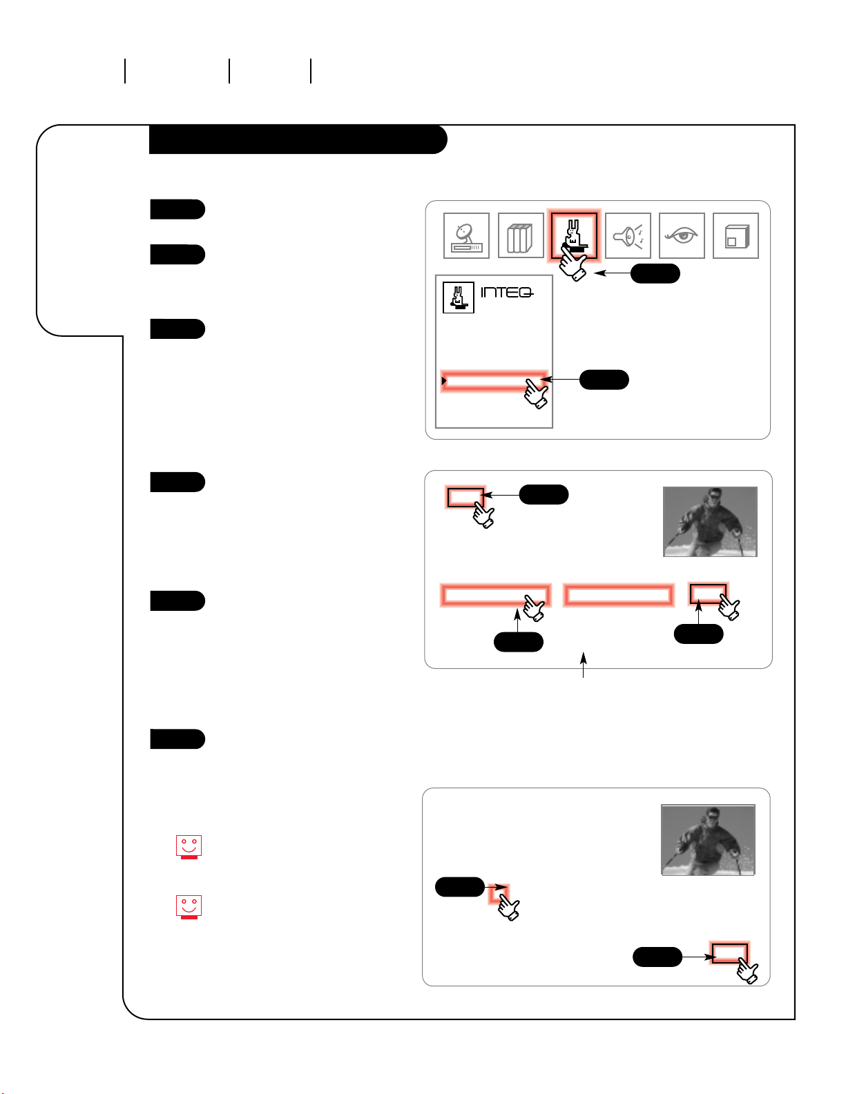
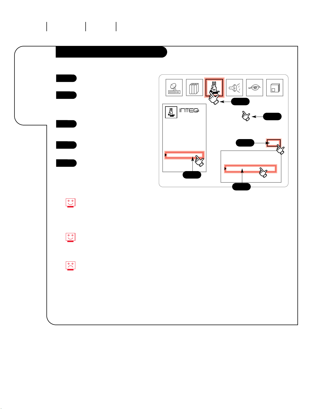
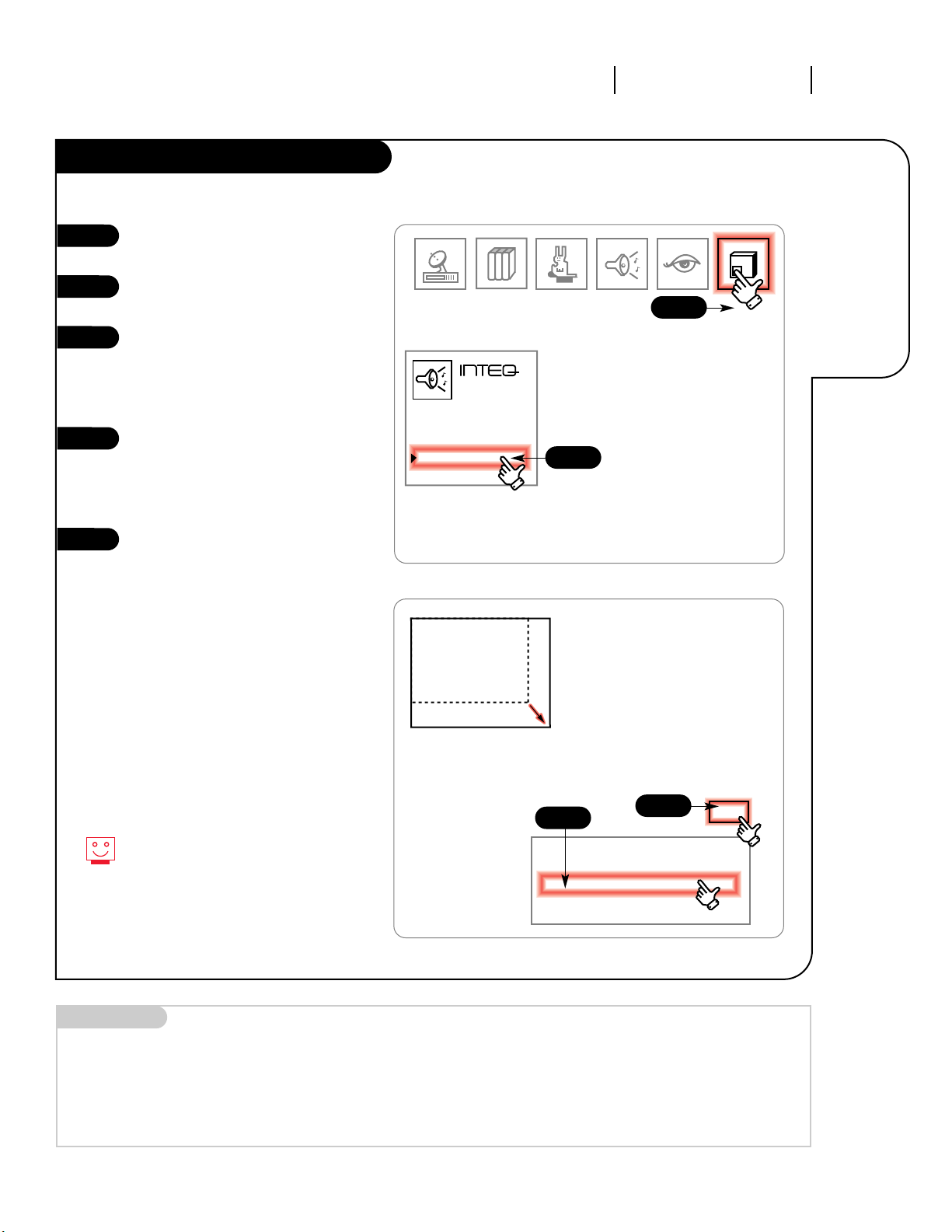
Click on your Features icon in the
menu display.
Select Parental Ctl. in the menu by
clicking on it. Click again to enter the
parental control menu (Par. Ctl).
Click on Block Ch. and the screen will
be replaced by a blue screen listing all
of your available channels. Click on
the channel numbers that you wish to
block. The screen lists the channel as
Unblocked. Click on the channel again
and it will read Blocked. Click EXIT to
return to the parental control menu.
Click Block Video and you will be
given the option to block all Video
inputs except Ant/Cable 1 and 2.
Select Set Hours in the menu by
clicking on it. Click again to set the
amount of time you want the channel
blocked for: 1 to 99 hours. Click on
arrows to increase or decrease the
time. Click EXIT to return to the
parental controls menu.
Click on Set Password twice to choose
a number that will protect the channel.
A display will appear on the bottom of
your screen, prompting you to enter a
four-digit code. Click on any four
numbers from the list, or enter a
number using the NUMBER KEYPAD on
your remote. After you enter it once,
you must enter it again to verify it.
After you verify the password, the
screen automatically displays Lock
On/Off
Click On or Off to have your Entertainment
Machine enable the channel blocking
(On), or to ignore it (Off).
1
2
3
4
5
6
7
123
Timer Setup
Ch. Labels
Source ID
Surf ID
Parental Ctl
Auto Demo
Features
Block Ch.
Block Video
Set Hours
Set Password
Lock On/Off
Par. Ctl.
1
6
11
16
21
26
31
36
41
46
51
56
61
2
7
12
17
22
27
32
37
42
47
52
57
62
3
8
13
18
23
28
33
38
43
48
53
58
63
4
9
14
19
24
29
34
39
44
49
54
59
64
5
10
15
20
25
30
35
40
45
50
55
60
65
More Channels
Ch 32
MTV
Unblocked
CABLE
SATELLITE
EXIT
1
3
3
3
2
If you do not set the hours or password, you will not be
able to enable the blocked feature.
Should you forget the password you activated, parental
control will automatically deactivate when the preset
time expires, which cannot be adjusted.
Page 34
OPERATION MENUS FEATURES MENUPAGE 34
Your
Entertainment
Machine will
show you
all your
menu options.
Auto Demo
3357-o
Click on your Features Menu icon
in the menu display.
Select Auto Demo in the menu by
clicking on it. Click on it again,
and a display will appear at the
bottom of your screen.
Decide whether you want the
Auto Demo On or Off, and click
on that option.
Click on EXIT to return to the
Features Menu.
Click on the regular screen to
have the Auto Demo begin.
Auto Demo displays many of the
menus and displays your Zenith
Entertainment Machine has, showing
you the layout and location of
your options.
To let you know it’s running,
Auto Demo places an animated
icon in the upper-right corner of
your screen.
Pressing any key on the remote or
front panel of your Entertainment
Machine will temporarily stop the
demo. To cancel the demo, you
must turn off the Auto Demo.
1
2
3
4
5
123
Timer Setup
Ch. Labels
Source ID
Surf ID
Parental Ctl
Auto Demo
Features
Auto Demo
Off
On
EXIT
1
5
2
3
4
Page 35

OPERATION MENUS AUDIO MENU PAGE 35
Customize
the sound
on your
Entertainment
Machine.
Audio Menu
3357-o
• Bass: Increase/decrease lower-end sounds.
•
Treble: Increase/decrease higher-end sounds.
• Balance: Allows you to put the sound more to
the left or right channel.
• Audio Mode: Choose from stereo sound,
mono, or Second Audio Programming (SAP).
•
SoundRite: Scans for changes in sound level
during commercials, then adjusts the sound
to match your current level.
• Front Surr: Turn the front surround sound
speakers on or off.
• Rear Surr: Increase or decrease the sound
level of the rear surround speakers.
• BBE Audio: Choose the level the BBE Sound
Control is set to.
• Speakers: Turn the regular speakers on or off.
Not all programming is broadcast in
stereo sound.
Programming that doesn’t broadcast SAP
may be silent when you set your
Entertainment Machine on this setting.
Mini glossary
STEREO SOUND Stereo (stereophonic) sound refers to audio that has right and left signals.
MONO SOUND Mono (monaural) sound is one channel of sound. On more than one speaker all the speakers play the same audio.
2ND AUDIO/SAP Second Audio Programming (SAP) is another, separate, audio channel available with some programming.
Choosing SAP often refers to listening to audio in another language, such as Spanish or French.
BBE SOUND CONTROL Expands the range of tones your sound system delivers, giving you higher highs, and lower lows.
Click on your Audio Menu icon from the
menu display. Your options are:
Click once on the item you want to
modify to highlight it.
Click again to enter the menu that lets
you change the settings. You will be
able to either click directly on any part
of the adjustment bar, or on arrows to
increase and decrease settings one step
at a time.
Click on EXIT to return to the Audio
Menu. Click on the regular screen to
return to normal viewing.
1
2
3
4
123
Bass
Treble
Balance
Audio Mode
SoundRite
Front Surr
Rear Surr
BBE Audio
Speakers
Audio
Bass
EXIT
1
4
2
3
Page 36

OPERATION MENUS VIDEO MENUPAGE 36
Customize the
picture quality
on your
Entertainment
Machine.
Video Menu
3357-o
• Contrast: Changes the amount of
difference between black levels and
white levels in your picture.
• Brightness: Increases or decreases the
amount of white in your picture.
• Color: Adjust levels of all colors.
• Tint: Adjust the relative amounts of the
color red and green in your picture.
• Sharpness: Raise or lower the
definition of the picture. The lower the
level, the softer the image will appear.
• Color Temp: Adjust the color qualities
of the entire picture at once: warm,
medium, and cool.
• Video Filter: Reduces noise to enhance
picture clarity.
• Skin Tone: Automatically adjusts the
appearance of skin color, making it
more natural.
• Video Preset: Choose from a range of
options depending on your viewing
situation. Custom uses the settings you
have manually chosen, while Preset
restores the levels to their original settings.
Someone left the picture looking
terrible? Just choose Preset under
Video Preset to get the regular picture
back quickly.
Your modified video selections can be
different for each source. Modifying
the settings in one source will not
change settings in another source.
Click on your Video Menu icon from
the menu display. Your options are:
Click on the item you want to
modify to highlight it.
Click again to enter the menu that
lets you change the settings. You
will be able to either click directly
on any part of the adjustment bar,
or on arrows to increase and
decrease settings one at a time.
Click on EXIT to return to the Video
Menu. Click on the regular screen to
return to normal viewing.
1
2
3
4
123
Contrast
Brightness
Color
Tint
Sharpness
Color Temp
Video Filter
Skin Tone
Video Preset
Video
Contrast
EXIT
1
4
2
3
Page 37

OPERATION PICTURE-IN-PICTURE PAGE 37
Picture-inpicture
explained.
PIP Overview
3357-o
YOUR PICTURE-IN-PICTURE FEATURE
The Picture-In-Picture (PIP) function allows you to put a smaller
picture, called the “inset,” on the bigger screen, or the “main”
picture. Don’t want to miss any of the big game, but hate
commercials? Just put the game in the inset, and surf with the
main picture.
2-TUNER PIP FEATURE
Normally, you would need some other piece of equipment, like a
VCR, to act as a tuner to receive and display a second channel at
the same time. Your Entertainment Machine eliminates that need
by giving you two tuners in one TV. PIP is always available, no
matter what equipment you have.
WORKING WITH PIP
This is where your MBR Trakball remote is put to the most use. All
of the functions PIP has are accessible through the menus that
pop up on-screen when you use your Trakball. There’s more about
that on the following page.
Just like your Entertainment Machine’s main screen, PIP will need
a source to take its image from. When you set the main screen
source to Antenna/Cable 1 or 2, the PIP source will automatically
set to that as well. You can adjust and/or request a different
source under the Source menu (see page 22).
PIP SNAPSHOT
This feature enables you to freeze the main image into the PIP frame
or view another image in the PIP frame with the touch of a button.
POSSIBLE REASONS FOR ADJUSTING PIP SOURCE
1. You use a cable box to receive premium channels, and have it
“looped out” on the back of the TV. Set the PIP source to the
cable box source, and the Inset will display the premium
channels, which can then be swapped with the main picture.
2. You want to watch a video tape, but keep scanning for another
movie or game. Set the PIP source to VIDEO 1, 2, or 3 and you
can watch the VCR and TV, swapping between the two.
Picture-in-Picture Main Picture
You cannot have the Main Source from Ant/Cable 1 and
the PIP source in Ant/Cable 2 or vice versa. PIP must
be the same Ant/Cable source as the main or one of the
video sources.
Page 38

OPERATION PICTURE-IN-PICTUREPAGE 38
Getting the
most from the
PIP and other
functions with
your remote.
PIP/Features Menu
3357-o
PIP
FREEZ
PIP
CHAN
CC
PIP On/Off
Turns the PIP
function on and off.
When this is on,
all the following
options are available.
When it’s off, only
this option, FREEZ
and Surf to PIP are
available.
PIP Swap
Flips the PIP
image with the
main picture.
Trakball Speed
Adjust how fast the
pointer moves in
relation to your
moving the Trakball.
Closed Captioning
Click this to enter
the closed caption
menu.
Sleep Timer
Adjust the amount
of time before
your Entertainment
Machine shuts itself
off. See page 28
PIP Size
Choose between a
large or small PIP
inset picture.
PIP Move
Click on this to place
the PIP anywhere.
Once you click you’ll
be moving the PIP
around. Click again to
set the PIP at that
location.
PIP Channel
Switch between channel selection for the
Main and PIP images.
PIP Source
Click here to set
the source signal
for the PIP.
Commercial Surf to PIP
With one click this puts
whatever is on the main
screen into the PIP set,
and lets you move through
your selected surf list, for
a one minute time period.
It will then automatically
return the picture back to
the main screen.
FREEZ
Lets you stop the
image on screen.
If PIP is on, the
picture in the inset
will freeze. If PIP
is off, the main
screen image will be
frozen and placed in
a PIP inset.
Audio Swap
Switches you
between the sound
that accompanies
the main picture,
and the sound for
the PIP inset.
The PIP functions can all be found in the on-screen
menu that appears when you roll the pointer to the left
side of the screen.
Page 39
OPERATION PICTURE-IN-PICTURE PAGE 39
Control
the picture
qualities
of your
PIP inset.
PIP Menu
3357-o
Mini glossary
PIP This is the most common way to refer to the Picture-In-Picture (PIP) option.
Click on your PIP Menu icon in
the menu display.
Select Size in the menu by
clicking on it once.
Click on it again and a display
will appear at the bottom of
your screen. You have two sizes
available for the PIP inset
picture: Small and Large.
Click on the size you want your
PIP inset to be. The inset will
appear and change size to show
you the difference, even if the
PIP has not been turned on.
To return to the menu and adjust
the other options, Contrast and
Tint, click on EXIT. Click on
the regular screen to return to
normal viewing. The PIP will then
disappear if it has not been
turned on.
Note: Contrast and Tint are
adjusted the same as they are in
the Video Menu, only now they
affect the PIP inset image. See
Video Menu page 36.
All the rest of the PIP options are
available using your Trakball. See
page 38 for a full description.
1
2
3
4
5
123
Contrast
Tint
Size
PIP
Size
Small
Large
EXIT
1
5
2/3
4
Small PIP
Large PIP
Page 40

Some functions of PIP can also be controlled
using the Channel/Time display.
Turn PIP on. Click the Trakball
once, and roll the pointer to the
right side of the screen.
The display will be in two parts.
The highlighted part will indicate
the mode you’re in (Main or PIP).
Click on the darkened part to
change to operating the other
mode.
If the bottom section (PIP) is
highlighted, you’ll be changing
stations in the PIP inset. To
change stations on the main
picture, highlight the top half
before changing channels.
Instead of going to the Audio
Swap option in the PIP/Features
Menu, simply click on the small
musical note icon on the left of
the Channel/Time display. The
note that is highlighted tells you
which audio you are listening to.
You can be listening to the PIP
audio, but still changing the main
picture’s channel.
1
2
3
4
OPERATION PICTURE-IN-PICTUREPAGE 40
Controlling
the Main
and PIP
audio/video
using your
Trakball.
Channel/Time and PIP Display
3357-o
Ch 07 - NBC
4:55
Mono
Ch. 05
Ch.
Ch.
All Chan
Flashback
Surf 1
PIP
Ch 07 - NBC
4:55
Mono
Ch. 05
Ch.
Ch.
All Chan
Flashback
Surf 1
PIP
Page 41
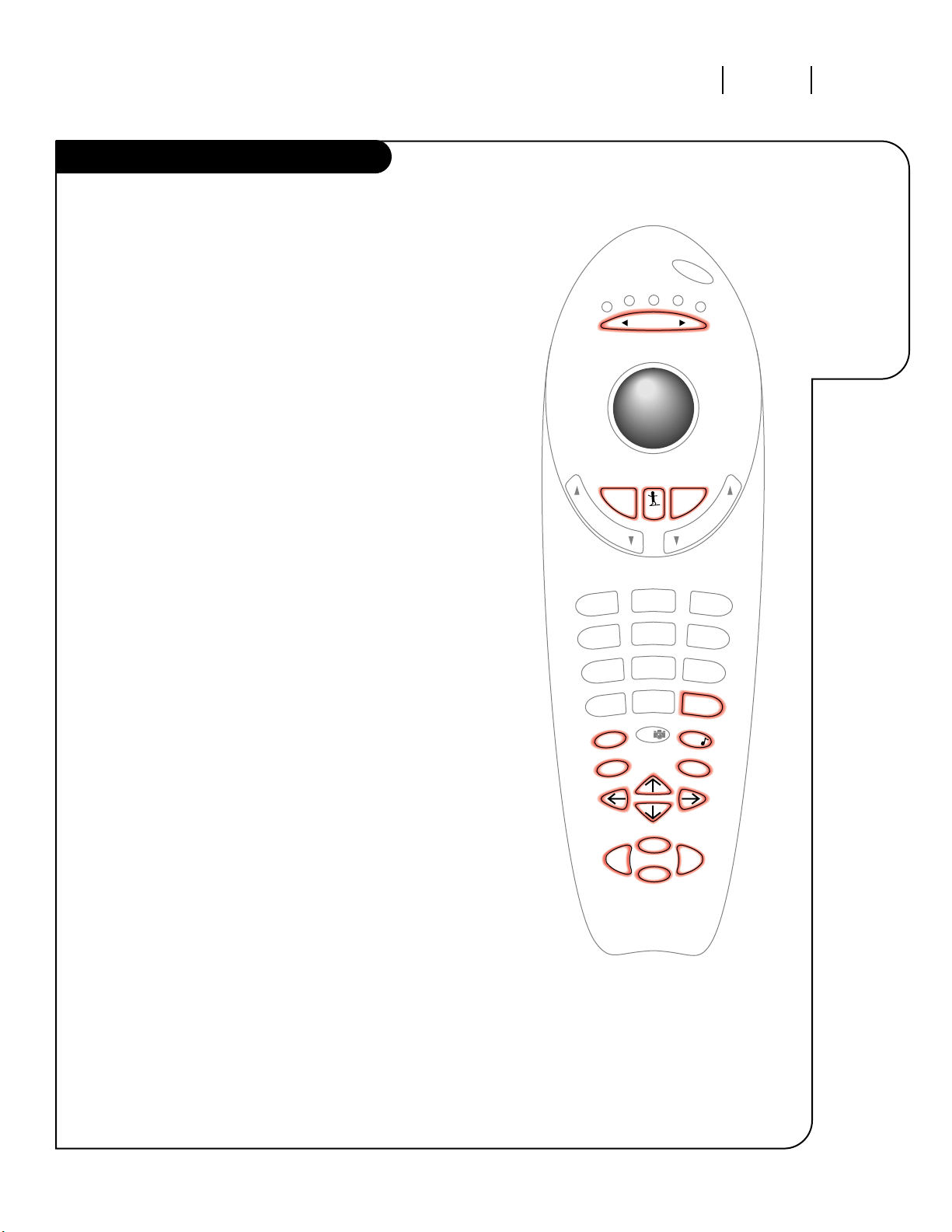
OPERATION REMOTE PAGE 41
Using your MBR Trakball Buttons
3357-o
Using the
buttons on
your remote to
control your
Entertainment
Machine.
You can use most of the options on your Entertainment Machine by
pressing various buttons.
MENUS
Pressing the MENU button repeatedly will cycle you through all the
available menus that control your Entertainment Machine’s settings.
Once in a menu, you can select an item by pressing the UP/DOWN
arrows to highlight one. Then, to modify that option, you can choose
it by pressing a RIGHT/LEFT arrow.
Changing labels and I.D.s require modifying options from a blue-screen
menu. In these menus all four of the arrow buttons will move the
cursor around the screen. Pressing FLSHBK will cycle through options
where the screen indicates.
Pressing ENTER will leave your current menu, and bring up the
Time/Channel Display. QUIT will leave the current menu, and take
everything off your screen.
SURF
The SURF button on your remote will cycle you through your
four surf menus.
The current Surf list will appear in the Surf display in lower right of
your screen. Surf 1-4 means that your channel changing using the
channel up or down will be limited to the channels that have been
chosen for your Surf list. When the list display reads No Surfing, then
all added channels will be available for you to choose from when
channeling up or down.
MODE
Your remote control can operate up to five different pieces of
equipment. These are called its “modes.” When you are using the
remote to operate your Entertainment Machine, it is in TV mode,
VCR mode when operating your VCR, and so on. There are modes available to control two “Auxiliary” items. This is for an external stereo system, or simply more VCRs, a DVD, Laserdisc, or any other piece of
home theater.
You can change the current mode by pressing either left or right on the
MODE button. An indicator will light to show you the current mode.
VCR/DVD FUNCTIONS
The buttons at the very bottom of your remote correspond to functions
for your Zenith VCR or DVD. The remote has already been programmed
with the code that operates most Zenith VCRs, so you can use those
buttons without have to go through the programming process. For any
other brand, refer to page 43 to see how to program new codes.
v
o
l
u
m
e
c
h
a
n
n
e
l
mode
mute
flshbk
source
enter
menu
record
pause
1
2
3
4
5
6
7
8
0
9
surf
power
tv
vcr
cable
aux 1
aux 2
quit/
pip
rew
stop
ffwd
play
Page 42

OPERATION FRONT PANELPAGE 42
Using the
ten-button
front panel to
operate the
menus.
Front Panel
3357-o
Press POWER on the control panel
to turn on your Entertainment
Machine.
To access the menus, push the
MENU button on the control
panel. Cycle through the various
menus by pushing the button
repeatedly.
Press the SELECT button
repeatedly to highlight the option
you want to modify.
Press either Right or Left on the
ADJUST button to modify the
option you have chosen.
Push the ENTER button to return
to normal TV viewing.
1
2
3
4
5
Refer to the various pages on how
to use the on-screen menus using
your remote.
The CHANNEL and VOLUME buttons
work just as they do on your
remote control.
Lost the remote? Call Zenith at
1-800-255-6790 to ask about
purchasing a new one. Any other
brand besides Zenith will not
perform all of the possible functions
on your TV.
5
ENTER ADJUST SELECT MENU VOLUME CHANNEL POWER
2
1
3
4
NOTE: The picture for the
IQA36A46W and the control
panel will be different than the
one shown.
Control Panel
Page 43
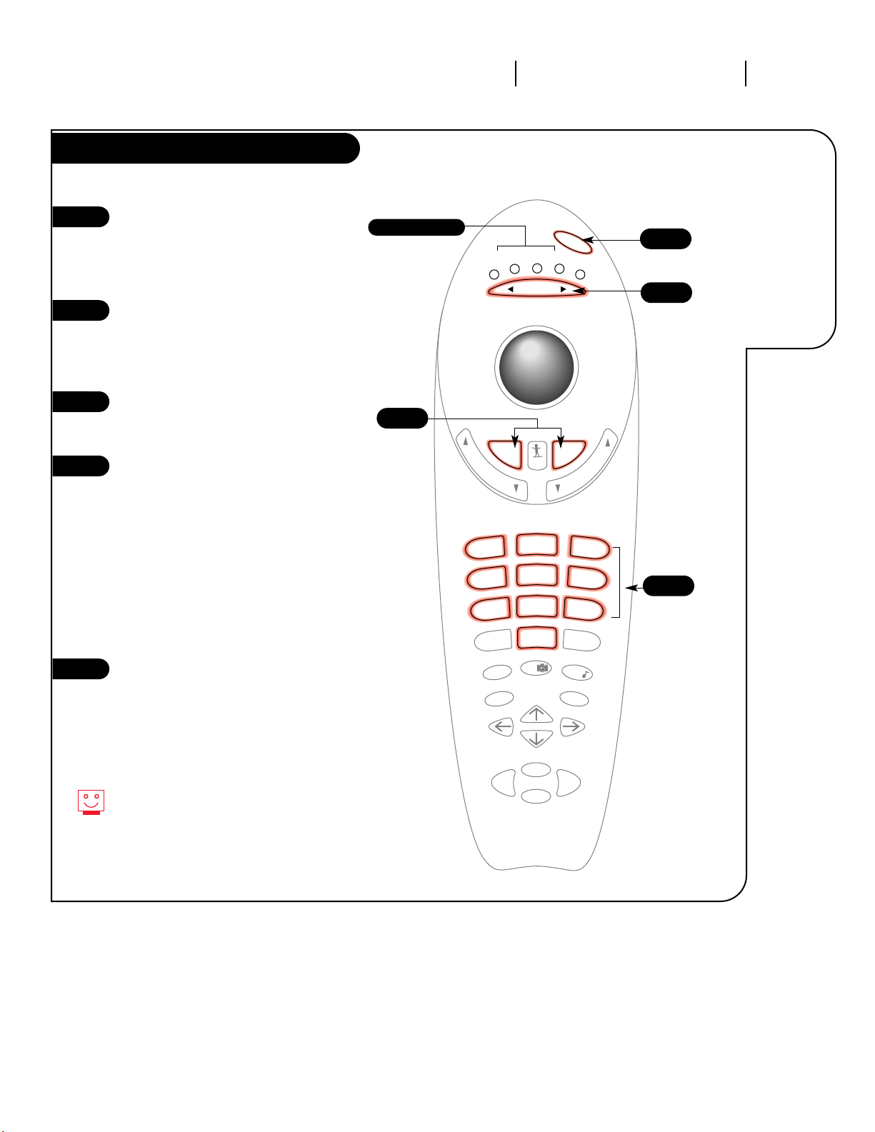
OPERATION PROGRAMMING THE REMOTE PAGE 43
Operate
all of your
home theater
and stereo
hardware
with the
MBR Trakball.
Programming the MBR Trakball Remote
3357-o
v
o
l
u
m
e
c
h
a
n
n
e
l
mode
mute
flshbk
source
enter
menu
record
pause
1
2
3
4
5
6
7
8
0
9
surf
power
tv
vcr
cable
aux 1
aux 2
quit/
pip
rew
stop
ffwd
play
2
3
4
5
Indicator lights
Select the equipment you want to
program, then turn to pages 44-45 to
find the programming code appropriate
for the type and brand of equipment.
Make sure the equipment is turned on.
Point the MBR Trakball remote at the
piece you’re programming, and press
MUTE and FLSHBK at the same time.
Hold until one of the mode indicator
LEDs lights.
Use the MODE Right/Left button
to select the appropriate mode for
your equipment.
With the Number Keypad, enter the
three digit code you found in step 1.
If the code is accepted, the mode
indicator LED will blink three times.
If it is not accepted, the LED will
not blink.
NOTE: The TV and VCR modes will only
accept codes for those types of products. The AUX 1, AUX 2, and Cable
modes will accept codes for any kind
of product.
Push the POWER button to turn off the
equipment. If nothing happens, repeat
the process from step 1, and try the
next code number.
To get out of Programming before
you enter a code, just press the
QUIT button on your remote.
1
2
3
4
5
Page 44

Admiral . . . . . . . . 116 121 130
133
Akai . . . . . . . . . . 104
Amark. . . . . . . . . 103 146
AOC . . . . . . . . . . 104
Bell + Howell . . . . 121
Broksonic . . . . . . 131 136
Candle . . . . . . . . 139
Centurion . . . . . . 119
Citizen . . . . . . . . 121 139
Contec . . . . . . . . 141
Coronado. . . . . . . 103
Crown . . . . . . . . . 103
Curtis Mathes . . . . 116 119 121
Daewoo. . . . . . . . 149 159
Daytron. . . . . . . . 119
Elektra . . . . . . . . 121
Emerson . . . . . . . 103 104 123
124 131 136
145 176
Fisher . . . . . . . . . 109 118
GE . . . . . . . . . . . 106 107 114
116 117 161
Goldstar . . . . . . . 103 104 119
147 184
Hitachi . . . . . . . . 102 103 121
129 163
lnteq . . . . . . . . . 101
JC Penney . . . . . . 104 110 114
117 119
JVC . . . . . . . . . . 125 132 164
KMC . . . . . . . . . . 103
KTV . . . . . . . . . . 103 104 138
Kurazai . . . . . . . . 121
LG . . . . . . . . . . . 184
Lodgenet. . . . . . . 121
Logik . . . . . . . . . 121
LXI. . . . . . . . . . . 119 133 137
Magnavox . . . . . . 103 112 113
117 119 127
128 130 139
165
Majestic . . . . . . . 121
Marantz. . . . . . . . 104 120 155
Megatron. . . . . . . 146
Memorex . . . . . . . 121
MGA/Mitsubishi. . . 104 119 120
130 133 140
155 169 178
Montgomery Ward 103 104 105
113 114 119
121 130 133
NEC . . . . . . . . . . 104 119
Orion . . . . . . . . . 176
Panasonic . . . . . . 106 107 160
166
Philco. . . . . . . . . 103 104 112
113 139
Philips . . . . . . . . 112 113
Pioneer . . . . . . . . 135
Portland . . . . . . . 103
ProScan. . . . . . . . 116 157 162
167
Quasar . . . . . . . . 106 107
RCA . . . . . . . . . . 104 116 126
157 161 162
167 168
Realistic . . . . . . . 105 123 124
Sampo . . . . . . . . 119
Samsung . . . . . . . 103 119 134
141
Sanyo . . . . . . . . . 108 109 118
Scott . . . . . . . . . 119 124
Sears . . . . . . . . . 103 108 109
110 111 118
134
Sharp . . . . . . . . . 103 105 122
133 137 156
169
Signature 2000 . . . 103 104 105
113 114 119
121 130 133
Sony. . . . . . . . . . 115 143 151
170
Soundesign . . . . . 139
Sylvania . . . . . . . 112 113 117
119 127 128
139
Tatung . . . . . . . . 106
Teknika . . . . . . . . 103 112 121
124 139
Telerent. . . . . . . . 103 121
Toshiba . . . . . . . . 110 111 134
171
XR-1000 . . . . . . . 121
Yorx . . . . . . . . . . 119
Zenith. . . . . . . . . 101 142 149
177
Zenith StarSight . . 175
OPERATION PROGRAMMING CODESPAGE 44
Find the codes
you need to
program your
remote.
Programming Codes
3357-o
TVs
VCRs
TV/VCRs
Adventura . . . . . . 154
Broksonic . . . . . . 182
Emerson . . . . . . . 158
Daewoo. . . . . . . . 148
Funai . . . . . . . . . 154
Goldstar . . . . . . . 153
Hitachi . . . . . . . 154
LXI. . . . . . . . . . . 154
Magnavox . . . . . . 173 181
Panasonic . . . . . . 174
RCA . . . . . . . . . . 179
Samsung . . . . . . . 180
Sansui. . . . . . . . . 182
Sharp . . . . . . . . . 179
Sylvania . . . . . . . 154
Symphonic. . . . . . 154
XR-1OOO . . . . . . . 154
Zenith. . . . . . . . . 153 154 172
182 183
Admiral . . . . . . . . 208 261
Adventura . . . . . . 231
Aiwa. . . . . . . . . . 231
Akai . . . . . . . . . . 223 238 241
Audio Dynamics . . 202 218 206
247
Broksonic . . . . . . 221 226 233
250 255
Canon . . . . . . . . . 214
Citizen . . . . . . . . 209
Craig. . . . . . . . . . 212
Criterion . . . . . . . 239
Curtis Mathes . . . . 214
Curtis Mathes . . . . 259
Daewoo. . . . . . . . 244 246 248
254
Daytron. . . . . . . . 236 246
DBX . . . . . . . . . . 202 218
Emerson . . . . . . . 203 209 221
223 226 233
235 243 250
Fisher . . . . . . . . . 211 212 213
247
Funai . . . . . . . . . 231
GE . . . . . . . . . . . 214 216 220
Go Video . . . . . . . 256 262 263
275
Goldstar . . . . . . . 209 273
Hitachi . . . . . . . . 215 231 257
Instant Replay . . . 214 227
lnteq . . . . . . . . . 273
JC Penney . . . . . . 214 215 218
227
JVC . . . . . . . . . . 202 224 225
258 268
Kenwood . . . . . . . 202
Logik . . . . . . . . . 239
LXI. . . . . . . . . . . 209 231
Magnavox . . . . . . 207 214 231
Marentz. . . . . . . . 207 218
Marta . . . . . . . . . 209
Memorex . . . . . . . 206 212 214
231
Mitsubishi . . . . . . 204 222 252
264
Montgomery Ward 208 214 216
219 231 249
Multi Tech . . . . . . 239
NEC . . . . . . . . . . 202 218
Optimus . . . . . . . 208 209 259
Orion . . . . . . . . . 233 250
Panasonic . . . . . . 214 251 259
Pentax . . . . . . . . 215
Philco. . . . . . . . . 207 214
Philips . . . . . . . . 207 214 227
Pioneer . . . . . . . . 210 215
Portland . . . . . . . 246
ProScan. . . . . . . . 216 260
Quasar . . . . . . . . 214 259
RCA . . . . . . . . . . 215 216 220
227 240 242
249 260 267
Realistic . . . . . . . 206 208 212
214 231
Samsung . . . . . . . 220 230 238
Sansui. . . . . . . . . 239
Sanyo . . . . . . . . . 206 212 247
Scott . . . . . . . . . 204 205 233
243
Sears . . . . . . . . . 206 209 211
212 215
Sharp . . . . . . . . . 208 261 272
Shintom . . . . . . . 239
Signature 2000 . . . 208 214 216
219 231 249
261
Sony. . . . . . . . . . 232 274
Sony Beta/VHS . . . 237
SonyVideo8 . . . . . 217
Sylvania . . . . . . . 207 214 227
Symphonic. . . . . . 231
Tashiko . . . . . . . . 209
Tatung . . . . . . . . 202
Teac . . . . . . . . . . 202 231
Teknika . . . . . . . . 209 234
Toshiba . . . . . . . . 205 215 271
Vector Research . . 204 218
XR-1000 . . . . . . . 239
Yamaha. . . . . . . . 202 218
Zenith. . . . . . . . . 201 224 225
229 273
Zenith Beta . . . . . 237
Page 45

OPERATION PROGRAMMING CODES PAGE 45
Find the codes
you need to
program your
remote.
Programming Codes
3357-o
Allegro . . . . . . . . 358 362
Allegro A-B Switch 361
Americast . . . . . . 383
DISH Network Satellite 389
GE . . . . . . . . . . . 367
Gemini . . . . . . . . 305 331 338
General Instrument 304 305 306
307 308 309
310 318
Hamlin . . . . . . . . 302 303 345
365 366
Hitachi DSS . . . . . 392 393
Hughes DSS . . . . . 392
Jerrold . . . . . . . . 304 307 308
309 310 318
360 363 382
JVC Satellite. . . . . 389
Kale Vision. . . . . . 335
Macom . . . . . . . . 321
Macom Satellite . . 314
Magnavox . . . . . . 334
Magnavox DSS . . . 390
NSC . . . . . . . . . . 335 339 368
369 370
Oak . . . . . . . . . . 311 332 342
Panasonic . . . . . . 313 320
Panasonic DSS . . . 386
Paragon (Zenith). . 333
Philips . . . . . . . . 347 350 352
354 355
Pioneer . . . . . . . . 315 343
Primestar Satellite 388
RCA DSS . . . . . . . 373 394
Radio Shack . . . . . 362
Regal . . . . . . . . . 366
Regency . . . . . . . 329
Samsung . . . . . . . 335
Scientific Atlanta 316 323 336
364
Sony DSS. . . . . . . 387
Sprucer . . . . . . . . 313
Standard Comp . . . 335
Stargate . . . . . . . 379
Texscan. . . . . . . . 339 356 371
Tocom. . . . . . . . . 317 318 346
Toshiba DSS . . . . . 391
Unika . . . . . . . . . 348
Unika . . . . . . . . . 362
United Satellite . . 344
Universal. . . . . . . 358 362
Vid Tech . . . . . . . 340
Video Way . . . . . . 349
Viewstar . . . . . . . 354 355 369
372
Zenith. . . . . . . . . 301
Zenith HT-2000. . . 353
Zenith PM . . . . . . 374
Zenith Drake Satellite 312 330
Zenith HD Set-Top 385
Zenith N|C Set-Top. 384 395
Zenith Satellite. . . 328 351 378
Denon. . . . . . . . . 402 403
Mitsubishi . . . . . . 403
Panasonic . . . . . . 405
Pioneer . . . . . . . . 402 403
Sanyo . . . . . . . . . 401
Sony. . . . . . . . . . 404
Zenith. . . . . . . . . 401
Akai . . . . . . . . . . 409 424
Carver . . . . . . . . . 510
Crown . . . . . . . . . 410
Denon. . . . . . . . . 411
Fisher . . . . . . . . . 412 438
Goldstar . . . . . . . 460
Harman/Kardon. . . 413
JVC . . . . . . . . . . 415
Kenwood . . . . . . . 412 416 417
441
Magnavox . . . . . . 421 422 433
434
Mitsubishi . . . . . . 423 424
NAD . . . . . . . . . . 425 426 447
Nakamichi . . . . . . 427 428
NEC . . . . . . . . . . 429
Onkyo . . . . . . . . . 430
Panasonic . . . . . . 431 432
Philips . . . . . . . . 421 433 434
Pioneer . . . . . . . . 431 435
Quasar . . . . . . . . 432
Radio Shack . . . . . 431 436 439
440 441
RCA . . . . . . . . . . 437
Sanyo . . . . . . . . . 438 439
Scott . . . . . . . . . 440
Sharp . . . . . . . . . 441 442
Sony. . . . . . . . . . 443 444 445
Soundesign . . . . . 461 498 501
502
Sylvania . . . . . . . 433
Teac . . . . . . . . . . 446
Technics . . . . . . . 432 459
Toshiba . . . . . . . . 447
Yamaha. . . . . . . . 448
Zenith. . . . . . . . . 460 461 498
501 502
Denon. . . . . . . . . 523 524
Marantz. . . . . . . . 521
Mitsubishi . . . . . . 525
Panasonic . . . . . . 523 524
Philips/Magnavox 521
Pioneer . . . . . . . . 527
Proscan. . . . . . . . 526
RCA . . . . . . . . . . 526
Sony. . . . . . . . . . 522
Toshiba . . . . . . . . 521
Zenith. . . . . . . . . 521
DVD PLAYERS
LASER DISC PLAYERS
AUDIO CD PLAYERS
AUDIO TAPE DECKS
AUDIO TUNER AND AMPLIFIERS
CABLE/SATELLITE/SET-TOPS
Carver . . . . . . . . . 510
Denon. . . . . . . . . 462 463
Fisher . . . . . . . . . 464 505
Goldstar . . . . . . . 460
Harman/Kardon. . . 465
JVC . . . . . . . . . . 466
Kenwood . . . . . . . 468 469 506
Marantz. . . . . . . . 472 503
Onkyo . . . . . . . . . 473
Panasonic . . . . . . 507
Philips . . . . . . . . 475 476
Philips/Magnavox 505
Pioneer . . . . . . . . 477 478 479
Radio Shack . . . . . 487 488
RCA . . . . . . . . . . 508
Realistic . . . . . . . 480
Sanyo . . . . . . . . . 481
Scott . . . . . . . . . 482
Sharp . . . . . . . . . 483
Sherwood . . . . . . 487 488
Sony. . . . . . . . . . 489 490 491
492
Soundesign . . . . . 461 498 501
502
Teac . . . . . . . . . . 494 495
Technics . . . . . . . 497 507 509
Yamaha. . . . . . . . 496
Zenith. . . . . . . . . 460 461 498
501 502 504
505
Denon. . . . . . . . . 455
Harman/Kardon. . . 456
JVC . . . . . . . . . . 457
Kenwood . . . . . . . 450
Onkyo . . . . . . . . . 458
Philips DCC . . . . . 454
Pioneer . . . . . . . . 451 478
Sony. . . . . . . . . . 452
Technics . . . . . . . 497
Technics DCC . . . . 454
Yamaha. . . . . . . . 453
Page 46

OPERATION SPECIAL FEATURESPAGE 46
Use the
Remote
control to
search for
all possible
programming
codes.
Auto Find
3357-o
v
o
l
u
m
e
c
h
a
n
n
e
l
mode
mute
flshbk
source
enter
menu
record
pause
1
2
3
4
5
6
7
8
0
9
surf
power
tv
vcr
cable
aux 1
aux 2
quit/
pip
rew
stop
ffwd
play
Turn on the device you want
to operate.
Press and hold the MUTE and
FLSHBK buttons until the
indicator light turns on.
Press MODE Left/Right until the
indicator light is underneath the
device you’re trying to program
(TV, CABLE, VCR, AUX).
With the NUMBER keypad, enter
the code 0-0-0 (zero-zero-zero),
then press the Enter key right away.
Aim the remote at the correct
device and push the Power
button. Allow a second to pass,
then push the Power button
again. Repeat until the device
turns off.
Push Enter to save the code.
The indicator light on the remote
will blink three times and then
turn off.
Press Power to turn the device
back on.
You can get out of Auto Find
quickly by pressing the Quit button.
If the indicator light does not turn
off while you push the Power key,
all the codes have been tried and
your device can't be programmed.
1
2
3
5
2
4
4
6
7
6
3
5/7
Indicator lights
Page 47

OPERATION SPECIAL FEATURES PAGE 47
Amplifier/Cable Volume Override
3357-o
Control the
volume on
your sound
amplifier
while in
other modes.
Find the code that operates your
amplifier. Test it to make sure it’s the
correct one by following the procedure in
the “Programming Your Remote” section.
Press and hold MUTE and FLSHBK on your
remote until the indicator light stays lit.
Press MODE Left/Right until the
indicator light is under the mode that
you want Amplifier Volume to appear,
for example, TV.
Enter the code for your amplifier (found
from step one).
Enter the special code: 4-9-9, then
quickly press the ENTER button. (The
indicator should blink and then turn off.)
To program your remote to operate your
cable box’s volume and muting controls,
repeat steps 1-5 using special code 3-9-9.
Your volume and mute keys now control
your amplifier, while all the other keys
still operate the Entertainment Machine.
To change everything back to default,
reprogram all buttons with their original
codes. See the “Programming Your
Remote” section, page 43.
If you can’t find the code for your
amplifier, use the Auto Find feature.
1
2
3
2
4
5
6
v
o
l
u
m
e
c
h
a
n
n
e
l
mode
mute
flshbk
source
enter
menu
record
pause
1
2
3
4
5
6
7
8
0
9
surf
power
tv
vcr
cable
aux 1
aux 2
quit/
pip
rew
stop
ffwd
play
3
5
4/5
Indicator lights
Amplifier Volume Override:
Cable Volume Override:
Mini glossary
AMPLIFIER An external machine that amplifies sound from a television, CD player, VCR, DVD or other A/V device.
Page 48

REFERENCE MAINTENANCEPAGE 48
Caring
for your
Entertainment
Machine.
Maintenance
3357-o
SCREEN CLEANING
1 Spray a small amount of glass cleaner on a soft cloth and wipe the screen until it’s clean.
2. Here’s a great way to keep the dust off your screen for a while. Wet a soft cloth in a mixture of lukewarm
water and a little fabric softener or dish washing detergent. Wring the cloth until it’s almost dry, and
then use it to wipe the screen.
3. Make sure the excess water is off the screen, and then let it air-dry before you turn on your
Entertainment Machine.
CABINET CLEANING
1. Use a soft cloth with a mild soap solution to wipe the cabinet (avoid using any cleaner that says
”industrial strength“ on the label.
2. Rinse the cloth and wipe the cabinet again.
3. Let the cabinet air-dry before turning the Entertainment Machine on.
EXTENDED ABSENCE
If you leave your Entertainment Machine dormant for a long time (such as a vacation), it’s a good
idea to unplug the power to protect against possible damage from lightning or power surges. If you use
an off-air antenna, you may also want to disconnect it from the back of your Entertainment Machine
before leaving.
PICTURE INTERFERENCE
Even though you may be getting cable, the signal may be weak, which means the quality of your
picture may suffer due to other factors. If there are problems with the image on your Entertainment
Machine, consult the Troubleshooting guide on the following pages.
VIDEO GAMES AND OTHER FIXED-PATTERN DISPLAYS
If you use your Entertainment Machine to play video games or for other uses that have single, fixed
images, such as a photo-CD player, you should avoid setting the Brightness level too high. If static
images, like network identification patterns, are left sitting for too long, they can leave a permanent
impression on the picture tube. You can reduce the chance of this happening by limiting the amount
of time you use the fixed-image display, and by reducing the contrast and brightness levels or using
the Game preset.
CLEANING THE TRAKBALL
Sometimes the Trakball gets greasy or dirty, which can affect it’s performance. To clean it, moisten a
cloth with a solution of dish washing detergent and water. Gently wipe the exposed area of the
Trakball, rolling it with your thumb. Allow the remote to dry before using it again.
NOTE: Do NOT use alcohol or other “cleaning fluids” anywhere on the remote control.
If you unplug your Entertainment Machine, you may have to reset the clock using the
Clock Set menu described earlier.
Careful and regular cleaning can extend the amount of time you will have with your new Entertainment
Machine. Be sure to turn the power off and pull out the plug before you begin any cleaning.
Page 49

REFERENCE TROUBLESHOOTING PAGE 49
Some quick
and easy
tips to fixing
problems
yourself.
Troubleshooting
3357-o
SYMPTOMS
Snowy picture and unclear sound.
Multiple images or ‘ghost shadows.’
Interference: Sharp lines across
the screen and lousy sound.
Normal picture but no sound.
No picture and unclear sound.
No picture and no sound.
No color, but the sound is O.K.
Picture has a big black box
on it, but the sound is O.K.
Picture has two horizontal
black bars, one on top and
one on bottom.
SOLUTIONS
• Check your antenna connection or location
• Check your cable input.
• Check to see if the TV/.VCR button on your VCR has the TV selected.
• Check your antenna direction and/or location.
• Check your cable input
• Make sure the cable from your antenna to your Entertainment Machine is
properly connected.
The following may cause image problems or distortion:
Electrical appliances, powerful lights, cars, trucks; computers or
portable phones; medical equipment
• If possible increase the distance between your Entertainment Machine and
the offending appliance. Or shut one of them off.
• Check volume levels.
• Make sure the TV is not Muted.
• Try another channel. The problem may be the broadcast, not your
Entertainment Machine.
• Are the Audio A/V cables properly installed?
• Are the wires for external speakers (if you have external speakers)
properly installed?
• Make sure your speakers turned on under the Audio menu.
• If your audio mode is set to SAP, that channel may not have a SAP program.
• Are you in TV or cable tuning mode, and should be in the other?
• Make sure output channels on all A/V equipment are on the same channel (3 or 4).
• Check that all connections are tight.
• Is the AC power plugged in?
• Check that your AC power outlet works. (Test it by plugging in something
else or try another plug.)
• Make sure your brightness and audio controls are set properly.
• Try another channel. The problem may be with the broadcast.
• Check the color control in the Video menu.
• Try another channel. The problem may be with the broadcast.
• The CC (closed caption) option may be in Text mode. Select Caption 1, or OFF
in the Captions/Text menu.(See page 25).
• Your program is in letterbox. This means that the shape of your TV is a
square, but the program is a rectangle. Think of the bars as empty space the
program doesn’t fill; not picture that’s blocked out. Because this format is a
direct representation of film as you see it in the movies, you are actually seeing
MORE of the program when you see those bars. Trust us.
Page 50

REFERENCE TROUBLESHOOTINGPAGE 50
Some quick
and easy
tips to fixing
problems
yourself.
Troubleshooting, cont’d
Remote control doesn’t work.
Indicator light on remote
comes on but remote doesn’t
transmit.
Menu options can’t be
changed or selected.
No picture or sound
when any non-cable source
is selected.
Weak or no Stereo Sound
when using a stereo VCR.
Desired PIP source is not
selectable.
The PIP inset is black or
lacks contrast .
The PIP inset is “snow” when
the source is Ant/Cable 1 or 2.
Time is incorrect.
If all else fails, call 1-800-365-1690, Mon-Fri. between 7:00 am and 8:00 pm
Sat. 8:00 a.m. and 5:00 p.m. Central Standard Time.
3357-o
• Make sure the batteries are fresh and installed properly.
• Make sure the battery on the single side (located on bottom right when remote
transmitter is pointed toward the Entertainment Machine) is polarized properly
(see page 13).
• Try unplugging your Entertainment Machine for a few minutes,
then plug it back in.
• Check to see if the source equipment has been turned on.
• Make sure that the connections are secure on the back of your Entertainment
Machine and on the source equipment.
• Check to see if all the connections are secure.
• Look in the Audio mode menu to see if all the settings are correct.
• You are using channel 3 or 4 to view your VCR. No stereo sound is present
under that decision.
• Your Entertainment Machine automatically sets the PIP source to
Antenna/Cable 1 or 2 if that is the source for the main picture.
• You might want to adjust the PIP picture settings under the PIP menu.
• Check that all the wires are connected properly.
• Check to see if your input source for PIP is set correctly.
• Look to see if the TV/VCR button on your VCR has the TV selected.
• Automatic: Check to see if PBS Channel is correct and then check
Time Zone/Daylight Savings time settings under Clock menu.
• Manual: Make sure the time was set initially. Probably power was lost.
Page 51

REFERENCE FEATURES PAGE 51
Here are a few
features that
make your
Entertainment
Machine more
fun to use.
Special Features
3357-o
ADVANCED SURF
In addition to your normal channel listing, you can customize up to four different channel
lists to fit different members of your family: movie channels for the kids, the sports channel for Dad, etc. See page 23 to set up surf channel lists and page 32 to customize the
names of your channel lists.
PIP SNAPSHOT
With the press of a button you can freeze the image from your main screen into a large
PIP inset. Pressing the button a second time enables normal PIP viewing. Pressing the
button a third time removes PIP from the main screen. See pages 37-39.
AUTOMATIC TIME SET
You can have your Entertainment Machine read a signal sent over PBS broadcasts, and set
the time and date automatically. See page 24.
CHANNEL LABELS
Instead of leaving it up to channel numbers to let you know what you’re watching, you
can choose labels for the various channels (HBO, CNN, ABC, etc.). You can also let the
Entertainment Machine use the labels that some stations broadcast themselves. See
Channel Labels, page 30.
SOURCE ID CUSTOMIZING
If you have a number of other pieces hooked up to your Entertainment Machine, instead
of trying to remember the name of the jack you hooked them up to, just refer to page 31
to customize the name of the equipment as it shows up under the Source Menu or on your
Channel/Time display.
PARENTAL CONTROL
Using a password-protection system, parents can block a channel that they don’t want
their kids to be watching. See page 33.
2-TUNER PIP
Televisions require to a tuner to turn signals into watchable programs. Conventional TV’s
only have one tuner, and require another machine, such as a VCR, to receive another set
of signals to use Picture-In-Picture. Your Entertainment Machine has a second tuner built
right in, so there is no need to rely on other equipment for your PIP display. See PIP
overview on page 37.
AUTO DEMO
To familiarize yourself with the layout of all your menu options and choices, Auto Demo
can be turned on. It will cycle through all the menus, displaying them on your screen for
a few seconds. See page 34.
Page 52

REFERENCE GLOSSARYPAGE 52
A complete
list of
definitions
for words
found in
this guide.
Glossary
3357-o
2-TUNER PIP This features allows you to view a second channel while maintaining a
picture on the main screen.
75 OHM RF CABLE The round cable that comes from an off-air antenna or cable service
provider. Each end looks like a hex shaped nut with a wire sticking
through the middle, and it screws onto the threaded jack on the back
of your TV.
A/V CABLES Audio/Video cables. Three cables bunched together—Right audio (red),
Left audio (white), and Video (yellow). A/V cables are used for stereo
playback of videocassettes and for higher quality picture and sound
from other A/V devices.
A/V DEVICE Any device that produces video or sound (VCR, DVD, cable box,
or television).
ADD This function lets you add new channels to the list that you’ll scroll
through when using your remote.
AMPLIFIER An external machine that amplifies sound from a television, CD player,
VCR, DVD or other A/V device.
ANTENNA The physical receiver of television signals sent over the air. A large
metal piece of equipment does not always have to be visible for your
home to be using an antenna.
BBE SOUND CONTROL Expands the range of tones your surround sound system delivers,
giving you higher highs, and lower lows.
CAPTIONS A form of subtitling that writes out the dialog for your program.
CAPTIONS WHEN Sets captioning to come on automatically when your volume is soft
MUTED muted or muted.
CLICK The act of pressing the Trakball on your remote to perform
highlighting, and activating a particular function/feature.
COMPONENT VIDEO Some video equipment (DVD, for example) uses three separate lines
(Y, R-Y, B-Y) to more precisely reproduce images. Your manual will
explain how this relates to your equipment.
CONVERGENCE This option lets you correct for color separation in your picture.
DATA PORT A jack for hooking up optional equipment that gives you access to the
Internet through your TV.
DAYLIGHT SAVINGS “Observed” means that your Entertainment Machine will adjust your
time setting at the appropriate times of the year. “Not Observed” will
not. Set this depending on whether your viewing area uses Daylight
Savings or not.
DELETE This function lets you remove channels that you don’t watch from the
list you’ll scroll through.
Page 53

REFERENCE GLOSSARY PAGE 53
A complete
list of
definitions
for words
found in
this guide.
Glossary, cont’d
3357-o
ICON A small graphic item on your screen that represents a function or
menu item.
INPUT Refers to the jack that receives a signal into the TV, VCR or other
A/V device.
JACK A connection on the back of a TV, VCR, or any other A/V device. This
includes the RF jacks and the Audio/Video jacks
that are color-coded.
MODE The mode determines the type of device (TV, VCR, Cable, Aux) that the
remote is controlling.
MONO SOUND Mono (monaural) sound is one channel of sound. On more than one
speaker all the speakers play the same audio.
OUTPUT Refers to the jack that sends a signal out of a VCR, DVD, or other
A/V device.
PIP This is the most common way to refer to the Picture-In-Picture
(PIP) option.
PIP SNAPSHOT Press to capture and freeze main picture within large PIP frame. Press
a second time and receive normal PIP from another channel. Press
again to remove PIP from the screen.
POINTER The image of the hand that appears on-screen and points to the
option you want to work with.
SECOND AUDIO Second Audio Programming (SAP) is another, separate, audio channel
PROGRAMMING/SAP available with some programming. Choosing SAP often refers to
listening to audio in another language, such as Spanish or French.
SIGNAL Picture and sound traveling through cable, or on the air, to your
television screen.
SOURCE The term for the equipment that provides audio and video information
to your Entertainment Machine. Antenna, VCR, DVD players, or
Cable Boxes are examples of sources.
STEREO SOUND Stereo (stereophonic) sound refers to audio that’s divided into right
and left sides.
SURF This function creates a customized list of your favorite channels.
You can access this group of channels by pushing the surf button on
the remote.
TEXT Arbitrary text not related to the program.
TUNER Any device that picks up broadcast signals and turns them into
picture and sound.
Page 54

REFERENCE INDEX
PAGE 54
Find what you
want quickly.
Index
3357-o
FEATURE. . . . . . . . . . . . . . . . . . . . . . . PAGE
2-Tuner PIP . . . . . . . . . . . . . . . . . . . . . . . . . . . . . . . . . . . 37, 51
Add/Del/Surf-Advanced Surf . . . . . . . . . . . . . . . . . . . . . . . . . . . 23
Amplifier/Cable Volume Override . . . . . . . . . . . . . . . . . . . . . . . . 47
Antenna Hookup . . . . . . . . . . . . . . . . . . . . . . . . . . . . . . . . . . . 6
Audio Hookups . . . . . . . . . . . . . . . . . . . . . . . . . . . . . . . . . 10-12
Audio Menu. . . . . . . . . . . . . . . . . . . . . . . . . . . . . . . . . . . . . . 35
Auto Demo . . . . . . . . . . . . . . . . . . . . . . . . . . . . . . . . . . . . . . 34
Auto Find . . . . . . . . . . . . . . . . . . . . . . . . . . . . . . . . . . . . . . . 46
Background . . . . . . . . . . . . . . . . . . . . . . . . . . . . . . . . . . . . . 27
Basic Television Operation . . . . . . . . . . . . . . . . . . . . . . . . . . . . 19
Batteries . . . . . . . . . . . . . . . . . . . . . . . . . . . . . . . . . . . . . . . 13
Button Functions . . . . . . . . . . . . . . . . . . . . . . . . . . . . . . . 16, 41
Cable . . . . . . . . . . . . . . . . . . . . . . . . . . . . . . . . . . . . . . . . . 6-8
Cable Volume Override . . . . . . . . . . . . . . . . . . . . . . . . . . . . . . . 47
Caption/Text Menu . . . . . . . . . . . . . . . . . . . . . . . . . . . . . . . . . 25
Channel Labels. . . . . . . . . . . . . . . . . . . . . . . . . . . . . . . . . . . . 30
Channel Search . . . . . . . . . . . . . . . . . . . . . . . . . . . . . . . . . . . 14
Channel/Time Display. . . . . . . . . . . . . . . . . . . . . . . . . . . . . . . 40
Clock Set . . . . . . . . . . . . . . . . . . . . . . . . . . . . . . . . . . . . . . . 24
Component Video. . . . . . . . . . . . . . . . . . . . . . . . . . . . . . . . . . . 9
Convergence . . . . . . . . . . . . . . . . . . . . . . . . . . . . . . . . . . . . . 15
DVD Player . . . . . . . . . . . . . . . . . . . . . . . . . . . . . . . . . . . . . . . 9
External Stereo . . . . . . . . . . . . . . . . . . . . . . . . . . . . . . . . . . . 12
Front A/V Panel . . . . . . . . . . . . . . . . . . . . . . . . . . . . . . . . . . . . 5
Front Panel Diagram . . . . . . . . . . . . . . . . . . . . . . . . . . . . . . . . 42
Glossary. . . . . . . . . . . . . . . . . . . . . . . . . . . . . . . . . . . . . . 52-53
Home Theater Set-up . . . . . . . . . . . . . . . . . . . . . . . . . . . . . . . 10
Hookup Directory. . . . . . . . . . . . . . . . . . . . . . . . . . . . . . . . . . . 3
Jack Pack. . . . . . . . . . . . . . . . . . . . . . . . . . . . . . . . . . . . . . . . 4
Language Menu . . . . . . . . . . . . . . . . . . . . . . . . . . . . . . . . . . . 26
Loop Out . . . . . . . . . . . . . . . . . . . . . . . . . . . . . . . . . . . . . . . . 7
Maintenance . . . . . . . . . . . . . . . . . . . . . . . . . . . . . . . . . . . . . 48
Page 55

REFERENCE INDEX PAGE 55
Find what you
want quickly.
Index, cont’d
3357-o
On/Off Timer . . . . . . . . . . . . . . . . . . . . . . . . . . . . . . . . . . . . . 29
On Screen Menus . . . . . . . . . . . . . . . . . . . . . . . . . . . . . . . . 20-21
Parental Control . . . . . . . . . . . . . . . . . . . . . . . . . . . . . . . . . . . 33
Picture-in-Picture (PIP). . . . . . . . . . . . . . . . . . . . . . . . . . . . 37-38
PIP Menu . . . . . . . . . . . . . . . . . . . . . . . . . . . . . . . . . . . . . . . 39
PIP Snapshot . . . . . . . . . . . . . . . . . . . . . . . . . . . . . . . . . . 37, 51
Programming the Remote. . . . . . . . . . . . . . . . . . . . . . . . . . . 43-45
Projo Setup. . . . . . . . . . . . . . . . . . . . . . . . . . . . . . . . . . . . . . 15
Quick Start . . . . . . . . . . . . . . . . . . . . . . . . . . . . . . . . . . . . . . 13
Remote Control Diagram . . . . . . . . . . . . . . . . . . . . . . . . . . . . . 16
Safety Information. . . . . . . . . . . . . . . . . . . . . . . . . . . . . . . . . . 2
Serial Number . . . . . . . . . . . . . . . . . . . . . . . . . . . . . . . . . . . . . 2
Sleep Timer. . . . . . . . . . . . . . . . . . . . . . . . . . . . . . . . . . . . . . 28
Source ID . . . . . . . . . . . . . . . . . . . . . . . . . . . . . . . . . . . . . . . 31
Source Menu . . . . . . . . . . . . . . . . . . . . . . . . . . . . . . . . . . . . . 22
Special Features. . . . . . . . . . . . . . . . . . . . . . . . . . . . . . . . . . . 51
Subwoofer . . . . . . . . . . . . . . . . . . . . . . . . . . . . . . . . . . . . 10-11
Surf ID. . . . . . . . . . . . . . . . . . . . . . . . . . . . . . . . . . . . . . . . . 32
Surround Sound Speakers. . . . . . . . . . . . . . . . . . . . . . . . . . . 10-11
Trakball Remote. . . . . . . . . . . . . . . . . . . . . . . . . . . . . . . . . 16-18
Troubleshooting. . . . . . . . . . . . . . . . . . . . . . . . . . . . . . . . . 49-50
VCR. . . . . . . . . . . . . . . . . . . . . . . . . . . . . . . . . . . . . . . . . . . . 8
Video Menu. . . . . . . . . . . . . . . . . . . . . . . . . . . . . . . . . . . . . . 36
Warranty. . . . . . . . . . . . . . . . . . . . . . . . . . . . . . . . . . . . . . . . 56
FEATURE. . . . . . . . . . . . . . . . . . . . . . . PAGE
To reach Zenith, call 1-800-365-1690, between 7:00 am and
8:00 pm, Sat. 8:00 a.m. and 8:00 p.m. Central Standard
Time.
Page 56
Order Today!
Call Toll-Free
1.800.255.6790
Use your Visa
or MasterCard to
order.
STAND ALONE SUB-WOOFER
The IQ25SW features dual 6-1/2" sub-woofers offering true 25
watts per driven channel and Fixed Bass Boost. This unit is
lightweight for easy placement and fits nicely with any decor.
The Automatic Standby Circuit cuts out the power after about 5
minutes of no signal so the speakers won’t burn out.
IQ25SW
ONLY $349.95
inteq audio/video accessories
SURROUND SOUND SPEAKERS
Extra power and the added dimension of surround
sound are combined in these two-way mini tower
speakers featuring dual 4-1/4" woofers. They’re rated
up to 100 watts of music power via the sub-woofer
crossover for unparalleled audio output. The rear
channel speakers are two-way 4-1/4" full range
speakers with 15 watts of power. Easy to follow
instructions for strategic positioning are included.
IQ8000
ONLY $349.95
PLUS 19.95
SHIPPING & HANDLING
PLUS 19.95
SHIPPING & HANDLING
Broken or lost remote? Perhaps you would just like the convenience of
having a second remote on hand. Order your replacement remote control direct from Zenith! To ensure that you receive the correct remote,
have your television's model number ready when you call.
ONLY $39.95
CV5000
ONLY $224.95
PLUS $4.95
SHIPPING & HANDLING
REPLACEMENT REMOTE
STEREO SURROUND SOUND SPEAKERS
For use with any Surround Sound compatible TV. These
speakers create a sound so real, it’s as if you were part of
the action. The convenient, space-saving shelf design
make these speakers an ideal addition to any
Home Theater System. The contemporary black
finish complements any room.
PLUS $17.95
SHIPPING & HANDLING
SUB-WOOFER CABINET
Powered by dual 6-1/2" sub-woofers,
the IQ50SD cabinet provides 25 watts
per driven channel and Fixed Bass
Boost. The sleek black cabinet features
glass doors and an Automatic Standby
Circuit that shuts itself down to
extend its lifespan. It will accommodate a 35"
TV with space to store all your video extras. Approx. dimensions: 36"
w x 24.5" d x 20" h.
IQ50SD
ONLY $349.95
PLUS 19.95
SHIPPING & HANDLING
Page 57

Your Zenith Limited Warranty
Direct-View Color TV Welcome to the Zenith family! We believe that you will be pleased with your new Zenith Entertainment Machine. Please read this war-
ranty carefully, it is a “LIMITED WARRANTY” as defined under Federal Law. This warranty gives you specific legal rights, and you may
also have other rights that vary from state to state within the U.S.A.
ZENITH RESPONSIBILITY
Service Labor During a period of 90 days from effective warranty date, Zenith will provide service labor by a Zenith authorized service center when
needed as determined by Zenith as a result of manufacturing defects.
Parts New or remanufactured replacements for factory-defective parts will be supplied by a Zenith authorized service center for one year
from effective warranty date (color picture tube — two years). Such replacement parts are warranted for the remaining portion of the
original warranty period.
Home Service Warranty service for 21” diagonal (U.S.A.) or larger screen size models is provided in the home in most cases. (Some repairs may
require the unit to be taken by the servicer to the repair facility and returned, at no additional charge.)
Not Covered This warranty covers manufacturing defects and does not cover installation, adjustment of customer controls in the home, installation
or repair of home antenna systems, cable converters or cable company-supplied equipment; it also does not cover damage due to
misuse, abuse, negligence, acts of God or other causes beyond the control of Zenith. Any alteration of the product after manufacture
voids this warranty in its entirety.
OWNER’S RESPONSIBILITY
Effective Warranty Date Warranty begins on the date of original consumer installation. For your convenience, keep the dealer’s dated bill of sale or
delivery ticket as evidence of the purchase date.
Operating Guide Read your Operating Guide carefully so that you will understand the operation of your set and how to adjust the customer controls.
Carry-In Service Models under 21” diagonal (U.S.A.) screen size must be taken to a Zenith authorized service center for warranty service
and must be picked up by the owner.
Antenna Reception problems caused by inadequate home antenna or faulty antenna connections are the owner’s responsibility.
Important Product Registration—Please fill out and mail your Product Registration Card. It is imperative that Zenith know how to reach
you promptly if we should discover a safety problem that could affect you.
Warranty Service For warranty service information, contact any Zenith authorized service center. Parts and service labor that are Zenith’s responsibility
(see above) will be provided without charge. Other service is at the owner’s expense. If you have any problem in obtaining satisfactory warranty service, call or write the Zenith Response Center. You must provide the model number, serial number and date of purchase
or date of original installation. Before you ask for warranty service, read “Maintenance And Troubleshooting” in your operating guide.
You might avoid a service call.
THIS WARRANTY IS IN LIEU OF ANY OTHER WARRANTY, EXPRESS OR IMPLIED, INCLUDING WITHOUT LIMITATION, ANY WARRANTY OF MERCHANTABILITY OR FITNESS
FOR A PARTICULAR PURPOSE, AND ZENITH SHALL NOT BE LIABLE FOR ANY CONSEQUENTIAL, INDIRECT, OR INCIDENTAL DAMAGES OF ANY KIND, INCLUDING LOST
REVENUES OR PROFITS IN CONNECTION WITH THE PRODUCT.
ZENITH CONSUMER SERVICES
Factory Owned Service Center
Home & Carry-in Service
Television/VCR
Parts and Accessories
PTV/Computer
Service Contracts Hours:
M-F 8-6, Sat 9-2
801 E. Roosevelt Rd
Lombard, IL 630-705-2830
Additional Zenith Picture Tube Protection Plan Available
Zenith offers you the opportunity to obtain additional long-term protection against failure of the picture tube in your new television.
Our Picture Tube Protection Plan enables you to avoid any unexpected picture tube repair expenses and keep your television in top condition.
It guarantees you a genuine Zenith replacement picture tube and service from a Zenith authorized service center.
Be sure to send in the Product Registration Card. We will send you an application for the Protection Plan near the expiration of the
two-year manufacturer’s warranty on the picture tube. For additional information call (847) 391-8757.
ZENITH ELECTRONICS CORPORATION
Zenith Response Center
1000 Milwaukee Avenue
Glenview, IL 60025-2493
Telephone (847)391-8752
Mon-Fri, 7:00 a.m.-8:00 p.m.
Sat. 8:00 a.m. - 5:00 p.m. CST
IN CANADA, WRITE OR CALL US AT:
LG Electronics
235 Superior Blvd.
Mississauga, Ontario, Canada LST-2L6
tel: (905)795-6240,
fax:(905) 670-2379
IN MEXICO, WRITE OR CALL US
LG Electronics
Av. San Andres Atoto, No 8
Col. San Andres Atoto, Naucalpan
Estado de Mexico,
C.P. 53500
tel; 01 (800) 50 481
y en el D.F. 359 43 55
fax 01 (800) 50 733
y en el D.F. 357 17 56
PAGE 56
REFERENCE WARRANTY
 Loading...