

Page 1
PRODUCT
MAINTENANCE
RELEASE
BULLETIN
Product Information:
Product Line :
Product Family :
Product Type:
Model Name(s) :
Market Introduction :
PMRB Revision :
PMRB Date :
EMAIL:
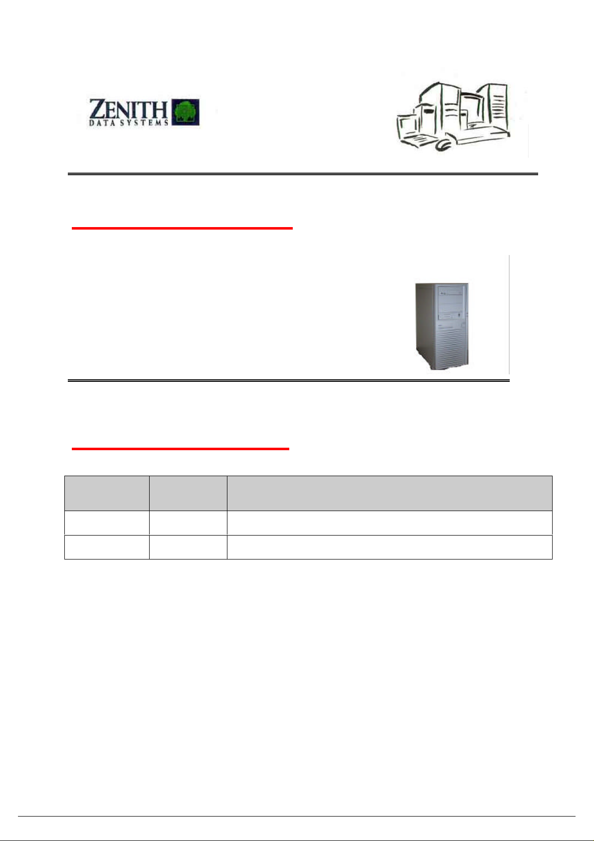
Servers
Express5800
LS2400
see below
June 1998
1.0
09 / 07 / 98
J.CHAABAN@FRDZ.BULL.FR
Model Identification:
Machine MI
LS2400
ISG-5470-HU PPRO 350Mhz, 512KB cache Model 0, NORAM, NOHDD
ISG-5491-XU PPRO 350Mhz, 512KB cache, 128MB/9GB
Description
** = Country codes: AA = Danish, BB = British, CD = Swiss/German, CF = Swiss/French, DD = German, EE = Spanish, FF = French, JJ
= Dutch, NN = Norwegian, PP = Portuguese, SS = Swedish, TT = Italian, TU = Italian /American, UU = Euro/American, YY =
Belgian/Flemish
EXPRESS 5800 HX4100/6100 Page 1/11
Page 2

Board supports the following features:
Ultra-Wide SCSI x 2 ch SYMBIOS
Yes (SMB Pro(PCI) or SMB Lite (ISA) :
DESCRIPTION COMMENTS
CPU
Memory Sockets
Memory Sticks
Max. Memory
Memory type, Speed, ECC
Incr. Memory
Internal Bays
Drive Bays, 5.25”
Drive Bays, 3.5”
TOTAL DRIVE BAY
SCSI Integrated
IDE integrated
RAID Contr.
Integrated NIC
Integrated Graphics
CDROM
Expansion Slots
TOTAL Expan SLOT
External I/F
I/F for RAS Board
Power Supply
Redundant and Hot Swap Power
Redundant and Hot swap FAN
Hot Swap FAN
Dimensions
(H x W x D)
Pentium II Klammath 266 L2 cache
Deshutes up to 400MHz L1/L2 cache
Up to 2 with a 100 MHZ BUS
512KB cache ECC
4
DIMM 32/64/128/256
1GB
SDRAM 72 Pin, 100MHZ, Yes
1 Stick, 4 Times
4
3
1
8
53C876
2 channels with PIIX4 up to 22 MB/s
NEC SECURAID 100/ 500 optional
On board 82558 10/100 PCI LAN
CL-GD5480 1280x1024, 16.7M colors
1MB not upgradable
24xCDROM 8240B
3 PCI
1 PCI/ISA shared
1 ISA
CRT,
Keyboard,
Mouse
Serial x 2
EPP Parallel x 1
Rj45 Network
TBI)
260W
NO
NO
NO
ATX
21.54x43.18x45.21cm
EXPRESS 5800 LS2400 Page 2/11
Page 3

Server supports the following features:
CPU stepping may be a consideration.
16MEG @ 640x480 & 800x600, 64K
DESCRIPTION FEATURE COMMENTS
CPU
Family Pentium II Klamath
Pentium II Deshutes
Internal frequency 266mhz,
300-400 mhz
External frequency 100 MHz
Total # of CPUs 2 CPU
2CPU :512KB cache
Supports 100 MHz
The CPU’s must be the same Mhz,
CACHE must be same size and
CACHE
Memory
Sockets 4
Capacity 1GB
Type X72
Data Protection ECC with error logging SDRAM
SCU & BIOS
BIOS Type Phoenix
Languages FLASH Update
Flash 1MB
Graphics
Controller CIRRUS Logic 5480
Bus PCI
Memory 2MB capacity standard
Resolutions 640x480, 800x600, 1024x768,
Colors
Output Port 15 pin analog
Disk Controllers
SCSI Ultra Wide Symbios53C876
IDE 2 Channels
Floppy connector on board
On CPU Chip
1280x1024
@ 1024x768 & 256 @ 1289x1024
(2 channels)
No Option Available
Gold sockets only
Supports 1GB using 256MB
SDRAM
Browse our Web
OS Dependent
BIOS Independent
2MB
1 channel : for Internal HDD bays
1 channel : for Internal 5» bays and
CHA A ultra Wide connector
CH B Narrow
I/O
Slots (Total) 6
Dedicated ISA 1
Dedicated PCI 3
Shared PCI/ISA 1
EXPRESS 5800 LS2400 Page 3/11
One of them is shared with SCSI
Page 4

Server supports the following features (con’t)
DESCRIPTION FEATURE COMMENTS
Ports & Connectors
On Base Board and
Riser Card
Output Ports
I/O Ports All Located On Riser Card -
Board
Dimensions
Length / Width ATX format
Real Time Clock
Server Management
Via PIAZZA &
HECETA
1 x Fan headers
1 x FDD interface
2 x SCSI 68 Pin Ultra Wide High
Density cabled to 2 connectors
( A Ultra, B Narrow)
1 x Power Supply
1 x Server management board I/F*
Contains the Following:
1 Mouse, 1 Keyboard port, 1 Serial
1 Parallel Port, 1 RJ45
National PC87306
SMB Pro or SMB Lite(not fixed)
CPU and Chassis Fan Alarm
Temperature Sensor
Voltage Sensor
Intrusion Detection
SMI
Shut Down
Event Log
SMB Interface(SMB Pro or Lite) è
BMC (Board management)
On System IO Board
On System IO Board
On System IO Board
On System IO Board
On System IO Board
On System IO Board
On System IO Board
On System IO Board
On System IO Board
I/O Chip
PIAZZA
HECETA
HECETA
PIAZZA + HECETA
HECETA + OSB2
PIAZZA
PIAZZA + NVRAM
PIAZZA
Hot Swap Backplane
Logging
Ease of Upgrade
EXPRESS 5800 LS2400 Page 4/11
All critical events to on board
non volatile memory
Easy upgrade of 2nd, CPU,
Main Memory,
(end user, not technician)
ECC Events, Voltage,
Temperature, Fan & Etc.
Page 5

Chassis supports the following features:
3.5» Removable Bays
5.25» Removable Bays
Add In Board Slots
DESCRIPTION FEATURE COMMENTS
Rack Mountable
HDD Bays
Power Supplies
Hot - Swap
Cooling
I/O Ports
Switches
Indicators
Fits into Std. 19”
Rack Frame
One 3.5» Bays
Three 5.25» Bays
Four SCSI SCA HDD
Device Bays
One 260 Watt Power
NO
For CPU
HDD bays
6
Riser Card
Power, Reset
Power, Fault, Activity, NIC
Activities
Side Rails fit both NEC Rittal 19” Rack Frame
(VR383551) and Compaq Rittal 19” Rack Frame
(165753-293)
Bay 1 - 3.5” FDD
Supports 5.25” SCSI Devices connected to
Internal SCSI controler
Support 18GB/10Krpm
ISA, PCI
Labeled on chassis with international icons
Labeled on chassis with international icons
EXPRESS 5800 LS2400 Page 5/11
Page 6

Operating System Specific Solutions
NOS specific information is key installation information for those NOS’s covered in the
Configuration Guide.
Utilities
• Express Builder Version 2.1 Setup and Configuration
⇒ SYM53C876 DRIVERS
⇒ Express5800 LS2400 UTILITIES, SSU
⇒ On Line service Manual, user’s Guide
⇒ AMI configuration Utilities,
• ESMPro Management Suite Version 1.4
Bios
• Express5800 LS2400 Flash PHENIX BIOS (see latest version on WEB)
• User & supervisor passwords supported
• DMI 2.0 capable
MAINTENANCE PLAN:
Under limited warranty, maintenance is performed to the major module assembly level. After
warranty, approved ZDS service organizations can perform maintenance as required. The Field
Replaceable Units (FRU) section of this PMRB lists the major assemblies.
APPROVED SERVICE ORGANIZATION:
Commercial Sales : Approved ZDS Service Centers and Field Engineers.
Contract Sales : Refer to applicable contract.
Zenith Data Systems reserves the sole right to determine, direct, and conduct any and all
factory-authorized reworks or upgrades, including the choice of service providers, based on
quality and cost of provider.
DATE OF FIRST SHIPMENT:
July 1998
TRAINING:
For service training in Europe, contact the Zenith Data Systems or Bull subsidiaries in each
country. A list of subsidiaries and phone numbers may be obtained by
calling ZDS in France at + (33) 1 5523 7200
EXPRESS 5800 LS2400 Page 6/11
Page 7

MEAN TIME TO REPAIR (MTTR)
At the major module assembly level, 30 minutes.
MEAN TIME BETWEEN FAILURES (MTBF)
20 000 h at 25°C and 40 % R.H.
PREVENTATIVE MAINTENANCE
Clock/Calendar battery replacement at seven years.
SPECIAL TOOLS OR UTILITIES REQUIRED
Full static prevention measures should be taken! Perform all work on a static mat using a wrist
strap. Utilities will be available on the Information Resource Program Technical Support
Bulletin Board until released on the Information Resource ZD-ROM.
Flash-BIOS (Use latest available from WEB)
Diagnostics TESTVIEW ( License required)
9-pin Serial Loopback Connector 438-0073-00
LIMITED WARRANTY:
Three years on site Warranty with high end class conditions.
MANUALS:
It is recommended to keep a copy of the following manuals:
A. Service Manual Ref. : online / Express builder 2.1
B. User Manual Ref. : online / Express builder 2.1
Information:
Zenith data systems standard: +(33).(0)1.5523.7200
Web: WWW.ZDS-EUROPE.COM
ATTACHMENTS:
A. Detailed views
B. I/O board layout
C. Exploded View
EXPRESS 5800 LS2400 Page 7/11
Page 8

ATTACHMENT A
DETAILED VIEW
Express5800 LS2400 Front & back Views
Front View Side view
I/O
Back view I/O board view
NIC
Manufacturers names shown are trademarked.
Copyright 1997 Zenith Data Systems Corporation, A division of Packard Bell NEC
EXPRESS 5800 LS2400 Page 8/11
Page 9

System Board Connector and Component Locations
D E FA CB
CC
BB
AA
Z
Y
X
W
V
Pri.
Sec.
G
H
I
J
K
L
M
N
O
U ST R Q
P
OM06957
Figure 2. System Board Connector and Component Locations
A. Secondary processor connector P. Server monitor module (SMM) connector
B. Primary processor connector Q. Narrow SCSI connector
C. Heatsink fan connector R. Wide SCSI connector
D. Diskette drive connector S. Memory sockets for four DIMM components
E. Main power connector T. PCI slots for add-in boards
F. Hard drive LED connector U. ISA slots for add-in boards
G. Front panel connector, 16 pin V. Heatsink fan connector
H. Speaker connector W. USB connector
I. AT front panel connector X. RJ-45 network controller
J. Lithium backup battery Y. Serial port B (COM 2)
K. System fan connector Z. VGA monitor port
L. IDE connectors, primary and secondary AA. Parallel port
M. External I
N. Configuration jumper blocks CC. Keyboard and Mouse PS/2 compatible connectors
O. System fan connector
2
C connector BB. Serial A (COM 1)
N440BX Product Guide 11
Page 10

Unavailable Yet
EXPLODED VIEW
EXPRESS 5800 LS2400 Page 10/11
Page 11

PARTS LIST
Description
No
1 MOTHERBOARD 1818970000
5 CPU 350 MHZ ECC W/512 UBP-2482-1C-xx 0820570000
7 RETENTION BRKT PII 1499770000
8 TERMINATOR BOARD 1301520000
10 HEATSINK PII è 300Mhz 1499520000
11 HEATPAD PII è 300Mhz 1499530000
12 DIMM, 32MB, 100MHz SDRAM Unbeffered AMS-4032-xx-30 0820610000
13 DIMM, 64MB, 100MHz SDRAM Unbeffered AMS-4064-xx-00 0820620000
14 DIMM, 128MB, 100MHz SDRAM Unbeffered AMS-4128-xx-00 0820590000
19 HDD, 4GB, 7200RPM, LVD, ST34573LW, ADH-7400-xx-30 3009110100
20 HDD, 9GB, 7200RPM, LVD, ST39173LW, ADH-7900-xx-30 3009130100
22 ADAPTEC AHA-2944UW HVD O 1301630000
32 Power Supply, (260 W) Hi-Pro 1901720000
33 CD-ROM, 24X EIDE 8240B ADR-0240-xx-04 7303020200
34 Diskette drive, 3.5”, Mist White 3200610000
38 CBL, IDE Z221100100
39 CBL, FDD 0700170000
40 CBL, POWER CORD 6701850000
41 CBL, USB 1301550000
45 BEZEL 1499690000
46 I/O PANEL 1499700000
52 POWER SWITCH 1499760000
56 FAN ASSY 3W PULSE QUABBIN 1301610000
TBD= To Be Defined Copyright 1997 Zenith Data Systems Corporation, A division of Packard Bell NEC
O KIT MODEL Part Number
EXPRESS 5800 LS2400 Page 11/11
 Loading...