

Page 1

© Copyright 2001, Zenith Electronics Corporation
Communication Interface System Setup Guide | Warranty
Models | HCS2000R, Head-End Unit • HCS100T, Card | for Concierge TVs
Page 2
RECORD MODEL NUMBER
The model and serial number are located on the product. For
future convenience, we suggest that you record these
numbers here:
MODEL NO.____________________________________
SERIAL NO.____________________________________
WARNING:
TO REDUCE THE RISK OF ELECTRIC SHOCK DO NOT REMOVE COVER (OR BACK). NO USER SERVICEABLE PARTS INSIDE.
REFER TO QUALIFIED SERVICE PERSONNEL.
The lightning flash with arrowhead symbol, within an equilateral triangle, is intended to alert the user to the presence
of uninsulated “dangerous voltage” within the product’s enclosure that may be of sufficient magnitude to constitute a
risk of electric shock to persons.
The exclamation point within an equilateral triangle is intended to alert the user to the presence of important operating
and maintenance (servicing) instructions in the literature accompanying the appliance.
WARNING:
TO PREVENT FIRE OR SHOCK HAZARDS, DO NOT EXPOSE THIS PRODUCT TO RAIN OR MOISTURE.
POWER CORD POLARIZATION:
CAUTION: TO PREVENT ELECTRIC SHOCK, MATCH WIDE BLADE OF PLUG TO WIDE SLOT, FULLY INSERT.
ATTENTION:
POUR ÉVITER LES CHOCS ÉLECTRIQUES, INTRODUIRE LA LAME LA PLUS LARGE DE LA FICHE DANS LA BORNE
CORRESPONDANTE DE LA PRISE ET POUSSER JUSQU’AU FOND.
NOTE TO CABLE/TV INSTALLER:
This reminder is provided to call the cable TV system installer’s attention to Article 820-40 of the National Electric Code
(U.S.A.). The code provides guidelines for proper grounding and, in particular, specifies that the cable ground shall be
connected to the grounding system of the building, as close to the point of the cable entry as practical.
REGULATORY INFORMATION:
This equipment has been tested and found to comply with the limits for a Class B digital device, pursuant to Part 15
of the FCC Rules. These limits are designed to provide reasonable protection against harmful interference when the
equipment is operated in a residential installation. This equipment generates, uses and can radiate radio frequency
energy and, if not installed and used in accordance with the instruction manual, may cause harmful interference to radio
communications. However, there is no guarantee that interference will not occur in a particular installation. If this
equipment does cause harmful interference to radio or television reception, which can be determined by turning
the equipment off and on, the user is encouraged to try to correct the interference by one or more of the following
measures:
• Reorient or relocate the receiving antenna.
• Increase the separation between the equipment and receiver.
• Connect the equipment into an outlet on a circuit different from that to which the
receiver is connected.
• Consult the dealer or an experienced radio/TV technician for help.
CAUTION:
Do not attempt to modify this product in any way without written authorization from Zenith Electronics Corporation.
Unauthorized modification could void the user’s authority to operate this product.
WARNING
RISK OF ELECTRIC SHOCK
DO NOT OPEN
Page 3
Head-End
Unit
Mens
Dept.
Sports
Dept.
Toy
Dept.
Hrdwe.
Dept.
Auto
Dept.
Food
Dept.
2
3
Signal
Combiner
Modulator
Outputs
Broadband
Amplifier
Signal
Combiner
Department TVs
Host Computer
Passive Signal
Splitter
4
5
6
1
Back of
Computer
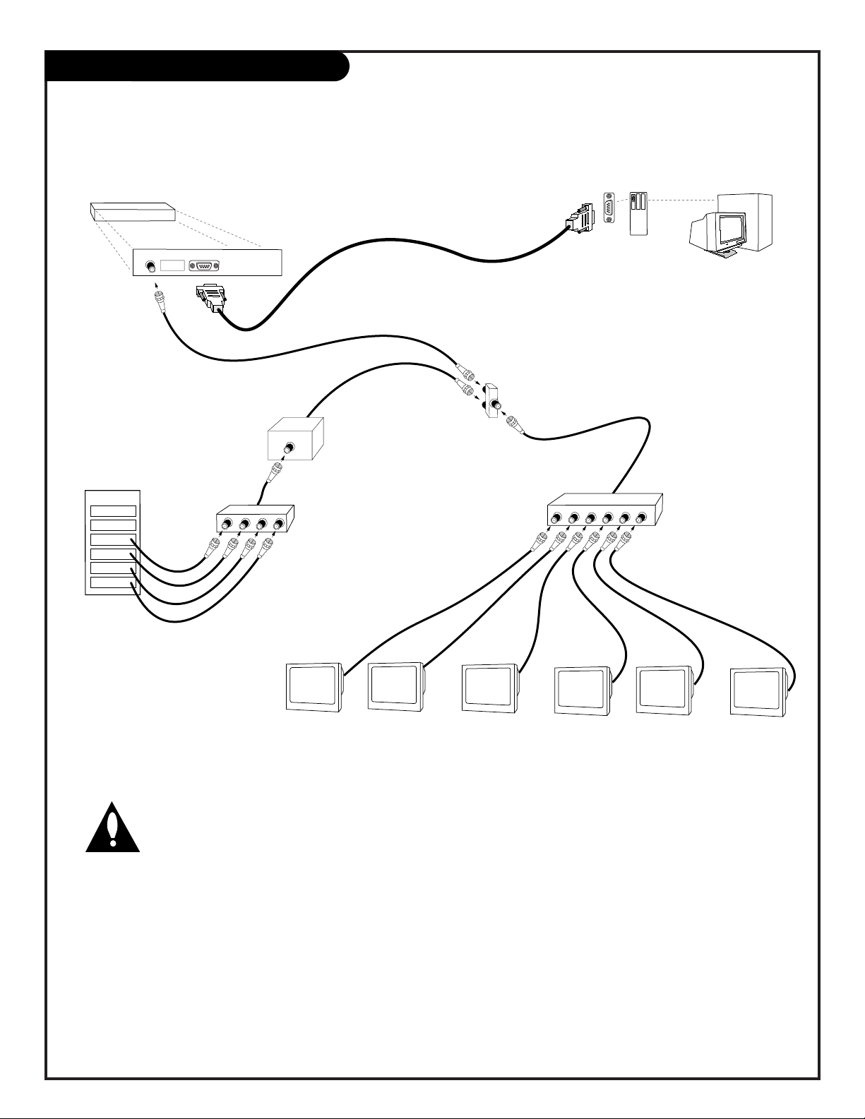
PRN System Setup Overview
Use this overview for reference to set up an in-store communications interface system
Important
Use of the sample equipment provided, as well as
with the other necessary equipment not provided,
may expose the operator to hazardous voltages. It is
assumed that the user is familiar with good safety
and handling procedures and precautions. Zenith assumes no liability for any damage to any equipment or injuries as a result of
working with the sample equipment provided.
System Setup Equipment
For testing and evaluation of the Zenith Communications
Interface Link system, and for development of the PRN proprietary software, the following items are required:
— HCS2000R unit.
— TV Modem Card HCS100T.
— Zenith Commercial Products Concierge Series television.
— DE9P to DE9S, “straight through” serial cable (not provided).
— Host computer with serial port (not provided).
— Two way 75 ohm splitter/combiner (not provided).
Optional Equipment Within System
— Broadband Amplifier (not provided).
— Modulator output sources (not provided).
— Passive signal splitter (not provided).
Power Supply
The HCS2000R prototype requires 120V AC, 60Hz, 1 Amp peak,
nominally drawing less than 50 watts. The connection is via
206-3594
PAGE 3
Page 4

System Overview
PAGE 4
3-WireRev6/00
polarized 2-co
nductor connector. Do not defeat this polariza-
tion. The wide blade pin is the neutral side of the power supply.
Computer
A computer with an RS232 serial port set at 1200, n, 8, 1;
connection is via DBE9 connector. The signals used are Tx,
Rx, and ground, on pins 2, 3, and 5. Do not connect or use
any other pins on this connector.
Software & Operating System
This unit has been tested using the Windows program,
Hyperterminal, on a Windows 98 and a Win NT4 platform. The
software in the unit is able to interact properly with
Hyperterminal, even when it generates a small delay (up to
115mS) between the first byte sent and subsequent bytes sent
from the computer to the unit.
Other operating systems and programs should work, provided
that they do not introduce any noise or erroneous data packets.
TV Interface
Communications between the Head End unit and the TV are via
the 75 ohm RF cable. Connection to the TV card and Head
End unit is via F-Connector.
Setup Instructions
To begin development of the PRN system software, the head
end unit and the TV card must be set up.
Head End Unit Communication Interface Link Setup
1) Plug the AC power cord into 120VAC 60Hz supply.
2) Attach one end of an F-connector RF cable to the F-connector on the rear of the HCS2000R unit. Connect the other end
of this cable to “A” half of the splitter.
3) Attach another piece of 75 ohm RF cable to the “B” half of
the splitter. Connect the other end of this cable to the RF
programming source (antenna, cable, etc).
4) Connect a long piece of 75 Ohm RF cable to the
“combine/input” port of the splitter. The other end of this
long cable shall be used to connect to the TV card.
5) Set the head-end to the desired a
ddress, default is $00h
(all dip switches set to ON).
6) Connect a “straight through”, serial cable between the
computer and the HCS200R unit via the DBE9 cable.
TV End Setup
Note: Each TV requires its own unique address.
(Required if the TV does not have a card)
1) Unplug the TV from AC power.
2) Remove the “MPI Card” from the SuperPort on the rear of
the TV.
3) Each TV requires its own unique a
ddress: Default is $FF, (all
switches off.) See “How to Set Dip Switch
Addresses” on page
...
4) Insert the TV modem card into the slot that originally contained the MPI card. Note: if it is too difficult to connect
the RF cable to the TV modem card, the TV back may be
removed to help facilitate the installation. Make sure that the
TV modem card is properly seated in the SuperPort card slot.
Head-End Unit
Communication Interface
TO CABLE
DISTRIBUTION
I.D.
CONFIGURATION
ON
3
1
5
4
2
6
COMPUTER
CONTROL
7
8
POWER
TV Back
ANTENNA
CABLE
M.P.I.
TV Back Connections Panel
(Expanded View)
VIDEO
IN
R- AUDIO- L
IN
MATRIX
OUT
Page 5

System Overview
206-3594
PAGE 5
5) Connect the other end of the F-connector RF cable (from the
HCS2000R unit, via the splitter) to the F-connector on the TV
modem card.
6) Connect an RF signal source (cable, antenna, vcr, etc) to the
F-connector on the TV modem card.
7) Plug the TV’s power cord into 120VAC 60Hz.
Protocol
The computer commands the TV by sending a packet of identification information, command type, arguments data, and checksum to the HCCS2000R. If successful, the HCS2000R responds
back to the computer with a status message consisting of identification information, command type, data, and checksum. If not
successful, an error message is returned.
Identification
At this time, the do not have the capability to contain and use a
unique electronic identifier, so indiv
idual TVs identification is
achieved via the dip switches contained on the TV modem card.
For test purposes, these switches are set to OFF, indicating “TV
#FFFF”. Setting these switches to any other value means that
any message generated by the host computer must have the TV
identification selected as part of the message packet, otherwise a
no response error will occur.
Similarly, the HCS200R unit has the capability of being uniquely
identified. Normally, this feature will not be required, so leave
the switches set to all “ON, identifying the head end as 00.
Finally, the MSB of the head end MUST be set to 0. This is done
in hardware, so the MSB dip switch setting will not have any
effect. Likewise, the TV modem card MSB MUST be set to 1. The
sample card does NOT yet have this in hardware, so please leave
the dip switch set to “OFF” to assure the correct setting.
Head End Computer to Microcontroller
Interface Protocol
The “head end” master computer shall interface to the “head
end” RF modem’s microcontroller via 1200 baud, 1/2 duplex, 8
bit word, 1 stop bit, no parity serial port. The commands from
the master computer to the modem shall consist of between 5
and 64 eight bit bytes total. However, this prototype is limited
to 20 bytes. The format shall be:
Byte Range Description
Master # 00-7F Head End RF Modem ID number (MSB is error
flag)
TVID1 80-FF Upper Nibble TV ID a
ddress (MSB is always 1)
TVID2 00-FF Lower Nibble TV ID a
ddress
TV Command 00-FF Command type directed to the TV
Number of Arguments 00-3A Number of argument bytes
to follow - can be 0 to 58
Argument 1 00-FF First Argument
Argument 2 00-FF Second Argument
.
.
.
Argument Last 00-FF Last argument
Check Sum 00-FF Modulo 256 check sum of all bytes
in command
Responses from the microcontroller back to the “head end” computer are of the same format with two exceptions: first, the
most significant bit of the Master # byte is set to a ‘1’ by the
Remove old MPI card
Install HCS100T TV Modem Card
Page 6

System Overview
PAGE 6
3-WireRev6/00
microcontroller if there was an error resulting from the previous
command; second, in an error response, the number of arguments is forced to be one, which is the error type code. The “TV
Command” byte returned by the microcontroller is forced to be
the “Error Code” response. This is a code that cannot be sent by
the “head end” computer, rather, it is a microcontroller to computer message value only.
The “head end” computer must wait for a response from the
microcontroller before sending a subsequent command string.
There is no “stack” of commands from the “head end” computer,
so the microcontroller shall ignore any command strings received
before the initial string behaviors have been completed. No
response from the microcontroller shall be given to such commands after the first one and before the first one has been
processed. In the event that the legitimate command is not
completed, due to the target TV not being present, or any other
error, the response from the microcontroller shall be the Error
Response with the appropriate Error Value. The maximum time
for the microcontroller to respond back to the “head end” computer shall not exceed 6 seconds nor be less than 20mS. All
commands sent from the “head end” computer shall be responded to by the microcontroller with the correct command or error
response.
TV Directed Commands and Responses
The following are the commands that can be sent by the “head
end” computer to indiv
idual TVs in the system. All commands
not defined in this document at this time are reserved for future
use and should not be implemented or included in any “head
end” computer software interface device behavior. Performance
may be unpredictable for any undefined commands used. Note
that the specific information used by the microcontroller to create the response message depends entirely on the data received
from the TV to which the command was directed. The specifics
of such data are detailed in a later section of this document and
in the MPI specification, 28-3977. Important: The portion of
the responses from the microcontroller that refer to the TV’s
Volume Level are not valid as of Feb. 2001. This is due to the
current model TVs’ inability to provide such information. The
response data received from the target TV will always show $00
for TVs regardless of the actual volume setting until such time as
the appropriate behavior is incorporated into the future models
of TV sets.
Command $01: Request TV Status
Arguments SENT from “head end” computer: none
Arguments RETURNED to “head end” computer: 2
Description: returns the signal, power, channel, and volume (if
available from TV) information
Data: the returned data is two 8-bit bytes, organized as follows:
Data Byte 1 (first data byte received):
Bit Description
7 TV Power, 1=ON, 0=OFF
6 TV Signal Status, 1=GOOD, 0=BAD
5-0 TV Volume Level (00=min, 63=max; this is not
available in all model TVs)
Data Byte 2 (second data byte received)
Bit Description
7-0 Channel Number, 00-FF (See MPI specification
for certain channel number definitions)
Example
“head end” computer sends: 01 01 80 01 00 83,
which means: “head end box” 01, TV number 8001, request status, no arguments, check sum the microcontroller responds: 01
01 80 01 02 D4 09 62
which means: “head end box” 01, TV number 8001, status message, 2 arguments, {power ON, signal GOOD, volume at 20/63},
{channel 9}, check sum.
Command $02: Turn TV ON
Arguments SENT from “head end” computer: none
Response: same as for Command $01.
Description: sends a command to the target TV to turn that TV’s
power ON
Example
“head end” computer sends: 01 01 80 02 00 84,
which means: “head end box” 01, TV number 8001, Turn TV ON,
no arguments, check sum the microcontroller responds: 01 01
80 02 02 D4 09 63
which means: “head end box” 01, TV number 8001, Power On, 2
arguments, {power ON, signal GOOD, volume at 20/63}, {channel
9}, check sum.
Command $03: Turn TV OFF
Arguments SENT from “head end” computer: none
Response: Status bytes, same as for Command $01.
Description: sends a command to the target TV to turn that TV’s
power OFF
Example
“head end” computer sends: 01 01 80 03 00 85,
which means: “head end box” 01, TV number 8001, Turn TV OFF,
no arguments, check sum
the microcontroller responds: 01 01 80 03 02 54 09 E4
which means: “head end box” 01, TV number 8001, Power OFF, 2
arguments, {power OFF, signal GOOD, volume at 20/63}, {channel 9}, check sum.
Command $04: TUNE CHANNEL
Arguments SENT from “head end” computer: 1; range of $00-$FF
Response: Status bytes, same as for Command $01.
Page 7

System Overview
206-3594
PAGE 7
Description: sends a command to the target TV to tune that TV
to the specified channel
Example
“head end” computer sends: 01 01 80 04 01 21 A8,
which means: “head end box” 01, TV number 8001, Tune
Channel, 1 argument, channel 33, check sum the microcontroller
responds: 01 01 80 04 02 D4 21 7D,
which means: “head end box” 01, TV number 8001, Tune
Channel, 2 arguments, {power ON, signal GOOD, volume at
20/63}, {channel 33}, check sum.
Command $05: SET VOLUME LEVEL
Arguments SENT from “head end” computer: 1; range of $00-$63
Response: Status bytes, same as for Command $01.
Description: sends a command to the target TV to set that TV’s
current volume level
Example
“head end” computer sends: 01 01 80 05 01 07 8F,
which means: “head end box” 01, TV number 8001, Set Volume,
1 argument, level 7/63, check sum
the microcontroller responds: 01 01 80 05 02 C7 09 59,
which means: “head end box” 01, TV number 8001, Set Volume,
2 arguments, {power ON, signal GOOD, volume at 7/63}, {channel
09}, check sum.
Response Command $00: ERROR MESSAGE
Arguments SENT from “head end” computer: NONE - this is a
response FROM the microcontroller only!
Response: Error, Error Code
Description: This is a way to have the microcontroller provide
error information to the “head end” computer. There can be
errors from several causes, so there are specific error codes which
indicate the type of error encountered. The following is the list
of error codes and their descriptions:
Error Code Description
$00 The command from the computer is not
recognized
$01 The command from the computer had insufficient
number of bytes
$02 The command from the computer had too many bytes
$03 The command from the computer check sum byte did
not match the command string computed check sum
$04 The command included an invalid TV a
ddress or
incorrect head a
ddress - note: the error response Head
End ID returned will be the actual ID from the Head End
unit, not the incorrect one received initially.
$05 The command included an invalid data argument value
or incorrect number of arguments
$10 The target TV does not respond
$11 The target TV did not acknowledge previous command
(not implemented yet)
$12 The target TV gave an unknown response
(not implemented yet)
$22 The microcontroller is busy waiting for the TV to
respond
Other error code values not shown are reserved for future use.
Example
“head end” computer sends: 01 01 80 01 00 83,
which means: “head end box” 01, TV number 8001, request status, no arguments, check sum
the microcontroller responds: 11 01 80 00 01 04 97,
which means: “head end box” 01 in error condition, TV number
8001, Error Message, 1 argument, error code 4 (invalid TV), check
sum.
Specifications
TBD!!!
Page 8

206-3724
Issue*
© Copyright 2001 Zenith Electronics Corporation
PRNWrnty7-1
For Customer Support/Service
Please call:
1-888-865-3026
www.zenith.com
Direct-View Color TV Welcome to the Zenith family! We believe that you will be pleased with your new TV. Please read this warranty carefully, it is a
“LIMITED WARRANTY” as defined under Federal Law. This warranty gives you specific legal rights, and you may also have other rights that vary from
state-to-state within the U.S.A.
ZENITH’S RESPONSIBILITY
Service Labor During a period of one year from effective warranty date, Zenith will provide service labor by a Zenith authorized service center when needed, as
determined by the Zenith service center, as a result of manufacturing defects.
Parts New or remanufactured replacements for factory-defective parts will be supplied by a Zenith authorized service center for one year from effective
warranty date (color picture tube — two years). Such replacement parts are warranted for the remaining portion of the original warranty period.
Warranty Service Warranty service is provided in the institution in most cases. (Some repairs may require the unit to be taken by the servicer to the repair facility and
returned, at no additional charge.) Call 1-888-865-3026 for further information.
Not Covered This warranty covers manufacturing defects and does not cover installation, adjustment of customer controls, installation or repair of antenna systems,
cable converters or cable company-supplied equipment; it also does not cover damage due to misuse, abuse, negligence, acts of God or other causes
beyond the control of Zenith. Any alteration of the product after manufacture voids this warranty in its entirety.
THIS WARRANTY IS IN LIEU OF ANY OTHER WARRANTY, EXPRESSED OR IMPLIED, INCLUDING WITHOUT LIMITATION, ANY WARRANTY OF
MERCHANTABILITY OR FITNESS FOR A PARTICULAR PURPOSE, AND ZENITH SHALL NOT BE LIABLE FOR ANY CONSEQUENTIAL, INDIRECT, OR
INCIDENTAL DAMAGES OF ANY KIND, INCLUDING LOST REVENUES OR PROFITS IN CONNECTION WITH THIS PRODUCT. SOME STATES DO NOT
ALLOW LIMITATIONS ON HOW LONG AN IMPLIED WARRANTY LASTS OR THE EXCLUSION OR LIMITATION OF INCIDENTAL OR CONSEQUENTIAL
DAMAGES, TO THE ABOVE LIMITATIONS OR EXCLUSIONS MAY NOT APPLY TO YOU.
OWNER’S RESPONSIBILITY
Effective Warranty Date Warranty begins on the date of installation of the Commercial Products Direct View Television Receiver.
For your convenience, keep the dealer’s dated bill of sale or delivery ticket as evidence of the purchase date.
Operating Guide Read your Operating Guide carefully so that you will understand the operation of the TV and how to adjust the controls.
Antenna Reception problems caused by inadequate antenna or faulty antenna connections are the owner’s responsibility.
Important Product Registration—Please fill out and mail the Product Registration Card. It is imperative that Zenith know how to reach you promptly if we should
discover a safety problem that could affect you.
Warranty Service For warranty service information, call 1-888-865-3026. Parts and service labor that are Zenith’s responsibility (see above) will be provided without
charge. Other service is at the owner’s expense. If you have any problem in obtaining satisfactory warranty service, call 1-888-865-3026.
You must provide the model number, serial number and date of purchase or date of original installation.
Before you ask for warranty service, read “Maintenance and Troubleshooting” in the operating guide. You might avoid a service call.
Your Zenith TV Warranty
 Loading...