

Page 1

machine numbers H2546DT H3246DT H3646DT IQB36C95W
H2547DT H2747DT H3247DT H3647DT
installation & operating guide / warranty
hookup directory
page
6
glossary
your on-screen menus
page
46
page
19
table of contents
page
5
computer hookup
page
12
Page 2

RECORD YOUR MODEL NUMBER
The model and serial number of your new TV are located
on the back of the TV cabinet. For your future convenience,
we suggest that you record these numbers here:
MODEL NO.____________________________________
SERIAL NO.____________________________________
WARNING:
TO REDUCE THE RISK OF ELECTRIC SHOCK DO NOT REMOVE COVER (OR BACK). NO USER SERVICEABLE PARTS INSIDE.
REFER TO QUALIFIED SERVICE PERSONNEL.
The lightning flash with arrowhead symbol, within an equilateral triangle, is intended to alert the user to the presence
of uninsulated “dangerous voltage” within the product’s enclosure that may be of sufficient magnitude to constitute a
risk of electric shock to persons.
The exclamation point within an equilateral triangle is intended to alert the user to the presence of important operating
and maintenance (servicing) instructions in the literature accompanying the appliance.
WARNING:
TO PREVENT FIRE OR SHOCK HAZARDS, DO NOT EXPOSE THIS PRODUCT TO RAIN OR MOISTURE.
POWER CORD POLARIZATION:
This product is equipped with a 3-wire grounding-type alternating current line plug. This plug will fit into the power
outlet only one way. This is a safety feature. If you are unable toinsert the plug fully into the outlet, contact your electrian to replace your obsolete outlet. Do not defeat the safety purpose of the three-wire ground type plug.
NOTE TO CABLE/TV INSTALLER:
This reminder is provided to call the cable TV system installer’s attention to Article 820-40 of the National Electric Code
(U.S.A.). The code provides guidelines for proper grounding and, in particular, specifies that the cable ground shall be
connected to the grounding system of the building, as close to the point of the cable entry as practical.
REGULATORY INFORMATION:
This equipment has been tested and found to comply with the limits for a Class B digital device, pursuant to Part 15
of the FCC Rules. These limits are designed to provide reasonable protection against harmful interference when the
equipment is operated in a residential installation. This equipment generates, uses and can radiate radio frequency
energy and, if not installed and used in accordance with the instruction manual, may cause harmful interference to radio
communications. However, there is no guarantee that interference will not occur in a particular installation. If this
equipment does cause harmful interference to radio or television reception, which can be determined by turning
the equipment off and on, the user is encouraged to try to correct the interference by one or more of the following
measures:
• Reorient or relocate the receiving antenna.
• Increase the separation between the equipment and receiver.
• Connect the equipment into an outlet on a circuit different from that to which the
receiver is connected.
• Consult the dealer or an experienced radio/TV technician for help.
CAUTION:
Do not attempt to modify this product in any way without written authorization from Zenith Electronics Corporation.
Unauthorized modification could void the user’s authority to operate this product.
WARNING
RISK OF ELECTRIC SHOCK
DO NOT OPEN
COMM-WARN B-3/99
Page 3

PAGE 3
206-3489-O 3-WIRE GRND
1. Read Instructions
All the safety and operating instructions should be read
before the product is operated.
2. Follow Instructions
All operating and use instructions should be followed.
3. Retain Instructions
The safety and operating instructions should be retained for
future reference.
4. Heed Warnings
All warnings on the product and in the operating instructions should be adhered to.
5. Cleaning
Unplug this product from the wall outlet before cleaning.
Do not use liquid cleaners or aerosol cleaners. Use a damp
cloth for cleaning.
6. Water and Moisture
Do not use this product near water for example, near a
bath tub, wash bowl, kitchen sink, or laundry tub, in a wet
basement, or near a swimming pool.
7. Accessories
Do not place this product on an unstable cart, stand, tripod, bracket, or table. The product may fall, causing serious
injury to a child or adult, and serious damage to the product. Use only with a cart, stand, tripod, bracket, or table
recommended by the manufacturer, or sold with the product. Any mounting of the product should follow the manufacturer’s instructions, and should use a mounting accessory recommended by the manufacturer.
8. Transporting Product
A product and cart combination should be moved with care.
Quick stops, excessive force, and uneven surfaces may
cause the product and cart combination to overturn.
9. Attachments
Do not use attachments not recommended by the product
manufacturer as they may cause hazards.
10. Ventilation
Slots and openings in the cabinet are provided for ventilation and to ensure reliable operation of the product and to
protect it from overheating, and these openings must not
be blocked or covered. The openings should never be
blocked by placing the product on a bed, sofa, rug, or
other similar surface. This product should not be placed in
a built-in installation such as a bookcase or rack unless
proper ventilation is provided or the manufacturer’s instructions have been adhered to.
11. Power Sources
This product should be operated only from the type of
power source indicated on the marking label. If you are not
sure of the type of power supply to your home, consult
your product dealer or local power company. For products
intended to operate from battery power, or other sources,
refer to the operating instructions.
12. Line-Cord Polarization
This product is equipped with a 3-wire grounding type
alternating-current line plug. This plug will fit into the
power outlet only one way. This is a safety feature. If you
are unable to insert the plug fully into the outlet, contact
your electrician to replace your obsolete outlet. Do not
defeat the safety purpose of the three-wire ground-type
plug.
13. Power-Cord Protection
Power-supply cords should be routed so that they are not
likely to be walked on or pinched by items placed upon or
against them, paying particular attention to cords at plugs,
convenience receptacles, and the point where they exit
from the product.
IMPORTANT SAFETY INSTRUCTIONS
Important safeguards for you and your new product
Your product has been manufactured and tested with your safety in mind. However, improper use can result in potential
electrical shock or fire hazards. To avoid defeating the safeguards that have been built into your new product, please read
and observe the following safety points when installing and using your new product, and save them for future reference.
Observing the simple precautions discussed in this booklet can help you get many years of enjoyment and safe operation
that are built into your new product.
This product complies with all applicable U.S. Federal safety requirements, and those of the Canadian Standards Association.
PORTABLE CART WARNING
(Continued on next page)
Page 4

(Continued from previous page)
14. Outdoor Antenna Grounding
If an outside antenna or cable system is connected to the
product, be sure the antenna or cable system is grounded so
as to provide some protection against voltage surges and
built-up static charges. Article 810 of the National Electrical
Code (U.S.A.), ANSI/ NFPA 70 provides information with
regard to proper grounding of the mast and supporting
structure, grounding of the lead-in wire to an antenna discharge unit, size of grounding conductors, location of
antenna-discharge unit, connection to grounding electrodes,
and requirements for the grounding electrode.
15. Lightning
For added protection for this product (receiver) during a
lightning storm, or when it is left unattended and unused
for long periods of time, unplug it from the wall outlet and
disconnect the antenna or cable system. This will prevent
damage to the product due to lightning and power-line
surges.
16. Power Lines
An outside antenna system should not be located in the
vicinity of overhead power lines or other electric light or
power circuits, or where it can fall into such power lines or
circuits. When installing an outside antenna system,
extreme care should be taken to keep from touching such
power lines or circuits as contact with them might be fatal.
17. Overloading
Do not overload wall outlets and extension cords as this can
result in a risk of fire or electric shock.
18. Object and Liquid Entry
Never push objects of any kind into this product through
openings as they may touch dangerous voltage points or
short-out parts that could result in a fire or electric shock.
Never spill liquid of any kind on the product.
19. Servicing
Do not attempt to service this product yourself as opening
or removing covers may expose you to dangerous voltage or
other hazards. Refer all servicing to qualified service personnel.
20. Damage Requiring Service
Unplug this product from the wall outlet and refer servicing
to qualified service personnel under the following conditions:
a. If the power-supply cord or plug is damaged.
b. If liquid has been spilled, or objects have fallen into the
product.
c. If the product has been exposed to rain or water.
d. If the product does not operate normally by following
the operating instructions. Adjust only those controls that
are covered by the operating instructions as an improper
adjustment of other controls may result in damage and will
often require extensive work by a qualified technician to
restore the product to its normal operation.
e. If the product has been dropped or the cabinet has been
damaged.
f. If the product exhibits a distinct change in performance.
21. Replacement Parts
When replacement parts are required, be sure the service
technician has used replacement parts specified by the manufacturer or have the same characteristics as the original
part. Unauthorized substitutions may result in fire, electric
shock, or other hazards.
22. Safety Check
Upon completion of any service or repairs to this product,
ask the service technician to perform safety checks to determine that the product is in proper operating condition.
23. Wall or Ceiling Mounting
The product should be mounted to a wall or ceiling only as
recommended by the manufacturer.
24. Heat
The product should be situated away from heat sources such
as radiators, heat registers, stoves, or other products
(including amplifiers) that produce heat.
PAGE 4
206-3489-O
IMPORTANT SAFETY INSTRUCTIONS
Antenna Lead in Wire
Antenna Discharge Unit
(NEC Section 810-20)
Grounding Conductor
(NEC Section 810-21)
Ground Clamps
Power Service Grounding
Electrode System (NEC
Art 250, Part H)
Ground Clamp
Electric Service
Equipment
Example of Grounding According to National Electrical
Code Instructions
NEC - National Electrical Code
Page 5

206-3492-O
PAGE 5
Table of Contents
Turn to the next page to begin the TV setup
Purchase the Optional Installer’s Remote and Clone Programmer
To preform the installation setup, you need an installer’s remote like the LP702, and the LT1500 Clone Programmer - both are shown and described in later sections. The installer remote allows access to the Service menus, User menus, and
Source/Channel Bank keys. The installer remote has Menu, Select, and Adjust Keys (Up/Down/Left/Right arrows) and
Source/Channel Bank Keys. The LT1500 Clone Programmer is used to duplicate a TV’s setup and install it on another TV.
See your Zenith Dealer.
PresentationTMTV is a trademark of Zenith Electronics Corporation
Safety Warnings . . . . . . . . . . . . . . . . . . . . . . . . . . . .2
Important Safety Information . . . . . . . . . . . . . . . . . . .3
Table of Contents . . . . . . . . . . . . . . . . . . . . . . . . . . .5
Step 1. Hook Up TV
TV/VCR/Cable Box/Computer and other Equipment Hookup
Antenna . . . . . . . . . . . . . . . . . . . . . . . . . . . . . . . . .7
Cable service . . . . . . . . . . . . . . . . . . . . . . . . . . . . . .8
Antenna with VCR . . . . . . . . . . . . . . . . . . . . . . . . . . .9
Cable service with VCR . . . . . . . . . . . . . . . . . . . . . . .10
S-VHS VCR/External Amplifier . . . . . . . . . . . . . . . . . . .11
Computer . . . . . . . . . . . . . . . . . . . . . . . . . . . . . . . .12
Computer Mode Remote Control Key command Functions .14
Step 2. Reception Setup and Channel Search
Auto Program: Select Antenna, or Cable service
and do channel search . . . . . . . . . . . . . . . . . . . . . . .16
Front Panel Controls/Inputs . . . . . . . . . . . . . . . . . . . .17
Remote Control Key Functions in TV mode . . . . . . . . . .18
On-Screen Menus Overview . . . . . . . . . . . . . . . . . . . . 19
Step 3. Customize the Presentation TV’s
Features
Setup Menu (Start with page 16, Auto Program)
Add/Del/Blank . . . . . . . . . . . . . . . . . . . . . . . . .20
Channel Labels . . . . . . . . . . . . . . . . . . . . . . . . .21
Clock Set . . . . . . . . . . . . . . . . . . . . . . . . . . . . .23
Alarm . . . . . . . . . . . . . . . . . . . . . . . . . . . . . . .24
Language . . . . . . . . . . . . . . . . . . . . . . . . . . . . .25
Audio Menu . . . . . . . . . . . . . . . . . . . . . . . . . . . . . .26
Video Menu . . . . . . . . . . . . . . . . . . . . . . . . . . . . . .27
Parental Control Menu . . . . . . . . . . . . . . . . . . . . . .28
Other Menus and On-Screen Displays
Source menu . . . . . . . . . . . . . . . . . . . . . . . . . . .30
Channel/Time/Audio Display . . . . . . . . . . . . . . . .30
Alarm menu . . . . . . . . . . . . . . . . . . . . . . . . . . .30
Sleep Timer menu . . . . . . . . . . . . . . . . . . . . . . .30
Volume Display . . . . . . . . . . . . . . . . . . . . . . . . .30
Closed Captions/Text menu . . . . . . . . . . . . . . . . .30
Ch Preview menu . . . . . . . . . . . . . . . . . . . . . . . .30
Installer Menus . . . . . . . . . . . . . . . . . . . . . . . . . . . .31
LT1500 Quickset Clone Programmer Operation . . . . . . . .34
Remote Control Programming . . . . . . . . . . . . . . . . . . .37
Amplifier Volume Override . . . . . . . . . . . . . . . . . .38
Aux 1, Aux 2, Aux 3 Programming . . . . . . . . . . . . .39
AutoFind . . . . . . . . . . . . . . . . . . . . . . . . . . . . .40
Programming Product Brand Codes . . . . . . . . . . . .41
Remote Modes Key Functions . . . . . . . . . . . . . . . .43
Maintenance . . . . . . . . . . . . . . . . . . . . . . . . . . . . . .44
Troubleshooting . . . . . . . . . . . . . . . . . . . . . . . . . . .45
Glossary . . . . . . . . . . . . . . . . . . . . . . . . . . . . . . . .46
Warranty for Presentation Series TVs . . . . . . . . . . . . . .48
Page 6
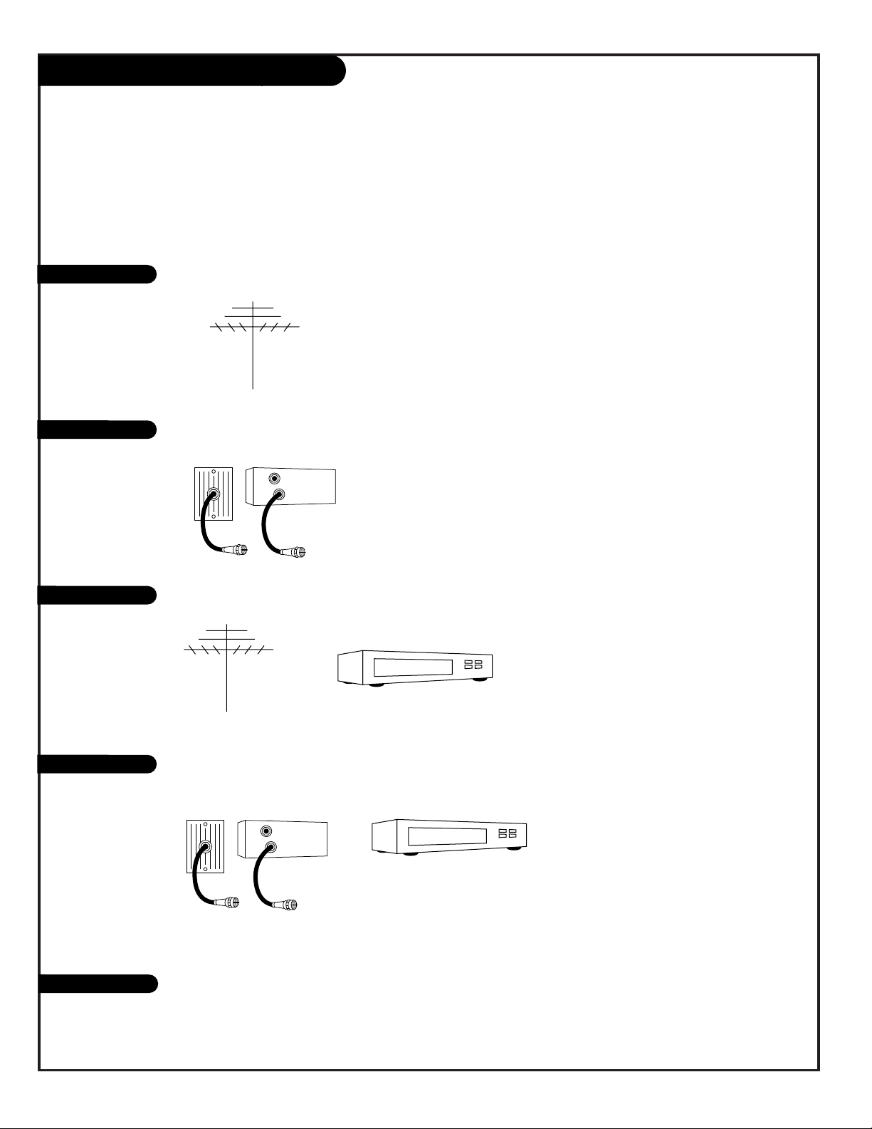
If you are using an antenna and no other equipment, go to . . . . . . . . . . . . . . . . . . page 7
If you have cable and no other equipment, go to . . . . . . . . . . . . . . . . . . . . . . . . . page 8
If you are using an antenna and have a VCR, go to . . . . . . . . . . . . . . . . . . . . . . . page 9
If you have cable and a VCR, go to . . . . . . . . . . . . . . . . . . . . . . . . . . . . . . . . . . page 10
If you want to connect an S-VHS VCR or External Amplifier with speakers . . . . . . . . . .page 11
206-3492-A
PAGE 6
Basic Hook-Up Directory
To hook up a computer see pages 12-13. To hookup other equipment, see below.
IMPORTANT!!
Use this page to decide where you need to begin your set up. First, find the line below that best describes what
you want to do, then go to that page number.
Cable TV
wall jack
Cable box
In
Out
Cable TV
wall jack
Cable box
In
Out
Antenna only
Cable only
Antenna with VCR
Cable and VCR
S-VHS VCR/Amplifier
Page 7

Mini glossary
75 OHM RF CABLE The wire that comes from an off-air antenna or cable service provider. Each end looks like a hex shaped nut with a wire
sticking through the middle, and it screws onto the threaded jack on the back of your TV.
A small device that connects a two-wire 300 ohm antenna to a 75 ohm RF jack. They are usually about an inch long with two screws
on one end and a round opening with a wire sticking out on the other end.
206-3492-O
PAGE 7
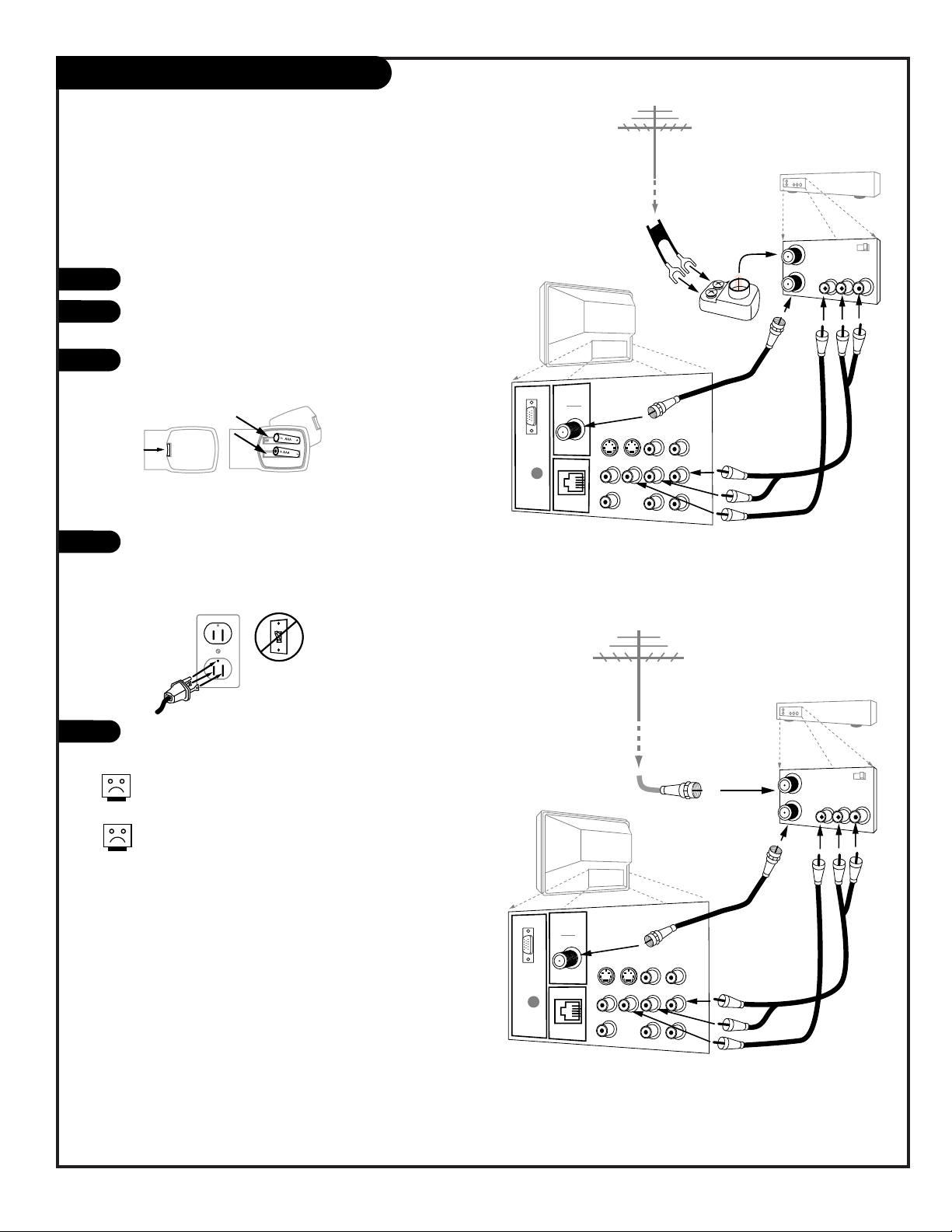
Hook Up Your Antenna to the TV
Connect an off-air antenna to the Presentation TV
If you have a 75 ohm RF cable, then you
don’t need any adapters!
A 300 to 75 ohm adapter is not included with
the Zenith Presentation TV.
300 TO 75 OHM
ADAPTER
TV back
VIDEO
ANTENNA
CABLE
R- AUDIO- L
S-VIDEO IN
COMPUTER
AUDIO
R
L
AUX IN
M.P.I.
R- AUDIO- L
R- AUDIO- L
S-VIDEO OUT
COMPUTER
IN
AUDIO OUT
Flat wire
(300 ohm)
Antenna
300/75 ohm
Adapter
RF coaxial wire
(75ohm)
Antenna
TV back
VIDEO
ANTENNA
CABLE
R- AUDIO- L
S-VIDEO IN
COMPUTER
AUDIO
R
L
AUX IN
M.P.I.
R- AUDIO- L
R- AUDIO- L
S-VIDEO OUT
COMPUTER
IN
AUDIO OUT
Locate the Antenna/Cable jack on the back of your
Presentation TV.
Connect the cable that runs from the wall directly to
this jack, according to the diagram to the right.
Remove the back of the remote and put in two AAA
batteries.
Plug in your TV. Do not plug it into a switched outlet. Your Entertainment Machine is designed to operate on standard current, 120-volt 60 Hertz AC. Do
not attempt to operate it on DC Current.
Go to page 16 to Auto Program your Presentation TV.
back of
remote
1
2
3
4
5
Page 8

206-3489-O
PAGE 8
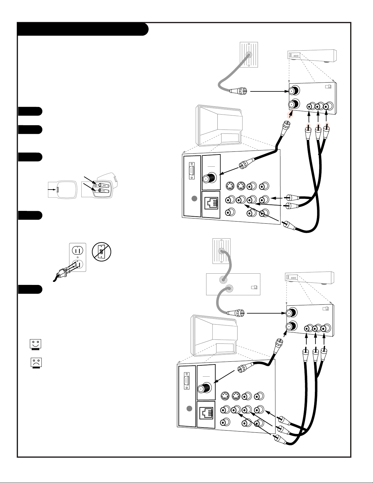
Hook Up Your Cable (CATV) to the TV
If you’re using a cable box, leave the TV on
channel 3 or 4 and use your cable box to
change channels.
If you’re using a cable box, Auto Program might
only find the channel your cable service is on
(usually channel 3 or 4). Don’t worry, that’s all
you need!
VIDEO
ANTENNA
CABLE
R- AUDIO- L
S-VIDEO IN
COMPUTER
AUDIO
R
L
AUX IN
M.P.I.
TV back
R- AUDIO- L
R- AUDIO- L
S-VIDEO OUT
COMPUTER
IN
AUDIO OUT
Cable TV
wall jack
Round wire (75ohm)
Cable TV
wall jack
Cable box
In
Out
RF coaxial wire (75ohm)
3 4
output
switch
VIDEO
ANTENNA
CABLE
R- AUDIO- L
S-VIDEO IN
COMPUTER
AUDIO
R
L
AUX IN
M.P.I.
TV back
R- AUDIO- L
R- AUDIO- L
S-VIDEO OUT
COMPUTER
IN
AUDIO OUT
Locate the Antenna/Cable jack on the back of
the Presentation TV.
Connect the cable that runs from the wall
directly to this jack, according to the diagram
to the right.
Remove the back of the remote and put in two
AAA batteries.
Plug in the TV. Do not plug it into a switched
outlet. Your Presentation TV is designed to
operate on standard current, 120-volt 60 Hertz
AC. Do not attempt to operate it on DC
Current.
Go to page 16 to Auto Program the
Presentation TV.
1
2
3
4
5
Connect cable service to the Presentation TV
back of
remote
Page 9
206-3492-O
PAGE 9
Hook Up Antenna and VCR to the TV
Connect your off-air antenna and VCR to the Presentation TV
No A/V cables are included with the Zenith Presentation
TV.
Without A/V cables, most VCRs will not play videocassettes in stereo sound.
In
Out
Audio
Video
3 4
VCR back
VCR back AV panel
output
switch
A/V cables
not included
with TV
Flat wire
(300 ohm)
Antenna
300/75 ohm
Adapter
VIDEO
ANTENNA
CABLE
R- AUDIO- L
S-VIDEO IN
COMPUTER
AUDIO
R
L
AUX IN
M.P.I.
TV back
R- AUDIO- L
R- AUDIO- L
S-VIDEO OUT
COMPUTER
IN
AUDIO OUT
In
Out
Audio
Video
3 4
VCR back
VCR back AV panel
output
switch
A/V cables
not included
with TV
VIDEO
ANTENNA
CABLE
R- AUDIO- L
S-VIDEO IN
COMPUTER
AUDIO
R
L
AUX IN
M.P.I.
TV back
R- AUDIO- L
R- AUDIO- L
S-VIDEO OUT
COMPUTER
IN
AUDIO OUT
RF coaxial wire
(75ohm)
Antenna
Locate the Antenna/Cable jack on the back of the VCR.
Connect the cable that runs from the antenna directly to
this jack, according to the diagram to the right.
Remove the back of the remote and put in two AAA bat-
teries.
Plug in the TV. Do not plug it into a switched outlet. The
Presentation TV is designed to operate on standard current, 120-volt 60 Hertz AC. Do not attempt to operate it
on DC Current.
Go to page 16 to Auto Program the Presentation TV.
1
2
3
4
5
back of
remote
Page 10
PAGE 10
206-3492-O
Hook Up Cable Service (CATV) and VCR
Connect a VCR and Cable service to the Presentation TV.
Leave the VCR and the television tuned to channel
three and use the cable box to change channels.
No A/V cables are included with your Presentation
TV. Without A/V cables, most VCRs will not play
videocassettes in stereo sound.
Cable TV
wall jack
RF coaxial wire (75ohm)
Cable box
In
Out
In
Out
Audio
Video
3 4
VCR back
VCR back AV panel
output
switch
3 4
output
switch
RF coaxial
wire (75ohm)
not included
with TV
A/V cables
not included
with TV
VIDEO
ANTENNA
CABLE
R- AUDIO- L
S-VIDEO IN
COMPUTER
AUDIO
R
L
AUX IN
M.P.I.
TV back
R- AUDIO- L
R- AUDIO- L
S-VIDEO OUT
COMPUTER
IN
AUDIO OUT
Cable TV
wall jack
Round wire (75ohm)
In
Out
Audio
Video
3 4
VCR back
VCR back AV panel
output
switch
RF coaxial wire
(75ohm)
not included
with TV
A/V cables
not included
with TV
VIDEO
ANTENNA
CABLE
R- AUDIO- L
S-VIDEO IN
COMPUTER
AUDIO
R
L
AUX IN
M.P.I.
TV back
R- AUDIO- L
R- AUDIO- L
S-VIDEO OUT
COMPUTER
IN
AUDIO OUT
Locate the Antenna/Cable jack on the back of the
VCR.
Connect the cable that runs from the wall directly
to this jack, according to the diagram to the
right.
Remove the back of the remote and put in two
AAA batteries.
Plug in the TV. Do not plug it into a switched
outlet. The Presentation TV is designed to operate on standard current, 120-volt 60 Hertz AC. Do
not attempt to operate it on DC Current.
Go to page 16 to Auto Program the Presentation
TV.
1
2
3
4
5
back of
remote
Page 11

PAGE 11
206-3492-A
Your Zenith TV may be connected to a Super-VHS VCR through the S-Video Input located on the connection panel on your TV. Also, you may “daisy chain” up to five TVs to one Super VHS VCR through the special S-Video LOOP OUT connection.
Hook up your S-VHS VCR to your Zenith TV according to
the diagram below.
Remove the back of the remote and put in two AAA batteries.
Plug in your TV. Do not plug it into a switched outlet.
Your Zenith TV is designed to operate on standard current,
120-volt 60 Hertz AC. Do not attempt to operate it on DC
Current.
If you wish to “daisy chain” more than one TV to receive
the S-VHS signal, you will need to make the following connections with an S-Video cable, inserting one end of the
cable into the LOOP OUT port with the other end inserted
into a S-Video In port of your second Zenith TV or equivalent input for any other brand of TV.
Audio Output: Use the Left and Right Audio Out jacks to
connect an external amplifier and speakers. (Refer to the
Audio Menu on page 26 for instructions on how to turn
the TV’s internal speakers off and on.)
1
2
3
4
4
back of
remote
Hook Up an S-VHS VCR to your TV
Audio
Audio
Page 12

PAGE 12
206-3492-O
VIDEO
ANTENNA
CABLE
R- AUDIO- L
S-VIDEO IN
COMPUTER
AUDIO
R
L
AUX IN
M.P.I.
TV back
R- AUDIO- L
R- AUDIO- L
S-VIDEO OUT
COMPUTER
IN
AUDIO OUT
Back of
Computer
Out to other
Monitor
"Video Mirror"
Cable
Make the basic connections as indicated. (Appearance of components may vary from those in the illustrations see page 13.)
Plug in your TV. Do not plug it into a switched outlet. Your
Presentation TV is designed to operate on standard current, 120volt 60 Hertz AC. Do not attempt to operate it on DC Current.
On the remote, press TV/VCR SOURCE repeatedly until
“REAR COMPUTER SVGA NTSC OUT” (Rear Computer in) is displayed, or “F COMPUTER SVGA” (Front Computer in) is displayed.
Boot up your computer. As it warms up, the TV will adapt to your
computer.
Hook Up a Computer to your TV
On some models, your new Zenith TV is furnished with the PCZTV scan
converter, giving you a TV-size “computer monitor.” You may use the
VGA and SVGA video format of either a PC or Macintosh 800 x 600
60Hz. And, because of multisync capability, you won’t have to change
the video settings of your computer—your TV will adapt for you! Here
is the basic setup as a monitor.
Components may vary from those in the
illustration. If you have a Macintosh, use the
2-row to 3-row DB15 adapter on their video connector.
On some notebook models you must locate the “display
toggle key” and switch the display to “external.” Refer
to the instructions for your computer.
You can also connect your computer to the Front input
jacks panel; specify F COMPUTER SVGA in the Source
menu; press TV/VCR SOURCE.
1
2
3
4
L audio R
video in
Page 13

PAGE 13
206-3492-O
An accessory packet is included with all models. A 15-ft. cable with a “video mirror” is featured that
provides signals to two monitors—your computer’s monitor and your Zenith TV—with a display.
Computer monitor
Video cable
from monitor
Actual appearance of
components may vary
Cable for
"video mirror"
Back of computer
VIDEO
ANTENNA
CABLE
R- AUDIO- L
S-VIDEO IN
COMPUTER
AUDIO
R
L
AUX IN
M.P.I.
TV back
R- AUDIO- L
R- AUDIO- L
S-VIDEO OUT
COMPUTER
IN
AUDIO OUT
Make the connections with the 15-ft. “video-mirror” cable as shown. Also refer
to the preceding page for audio connections and “Using the monitor function.”
1
Your TV must be plugged in—not necessarily turned on—for
the computer monitor to function.
You can ”Daisy Chain” other TVs via S-video loop and see the
computer display on more TV sets (see page 11 for details).
Hook Up a Computer to your TV
L audio R
video in
Page 14
PAGE 14
206-3492-A
Remote Key Command Functions
Remote Key Normal Mode Menu Mode Zoom Mode
1* Enter Zoom Mode N/A †† Increase Zoom or
Cancel Zoom Mode
2 N/A N/A Pan Up
3** Compress On/Off N/A Compress On/Off
4 N/A Menu Adjust Down Pan Left
5 Enter Menu Mode Cancel Menu Model Enter Menu Mode
6 N/A Menu Adjust Up Pan Right
7 †Auto Screen Size N/A N/A
8 N/A Menu Select/Next Pan Down
9 N/A N/A N/A
0 Freeze/Thaw N/A Freeze/Thaw
While your Presentation TV is in Rear Computer Mode, the table below
lists the commands used to make adjustments to the screen.
The following remote keys apply ONLY to the NUMBER keypad.
Adjust the screen options while in Computer Mode
Note: The following only applies to those TVs equipped with PCZ Scan Conversion technology
† Auto Size will adjust the computer image to match the TV Screen.
Use a full-screen computer display with high average brightness for best results.
* The image cannot be zoomed in Freeze Mode.
** Compress mode is not available in REAR COMPUTER SVGA as input. It is available
in REAR COMPUTER NTSC OUT as input source.
†† If Zoom Mode is enabled it will cycle through:
1:1, 2:1, 3:1, 4:1, then back to 1:1 etc.
Page 15
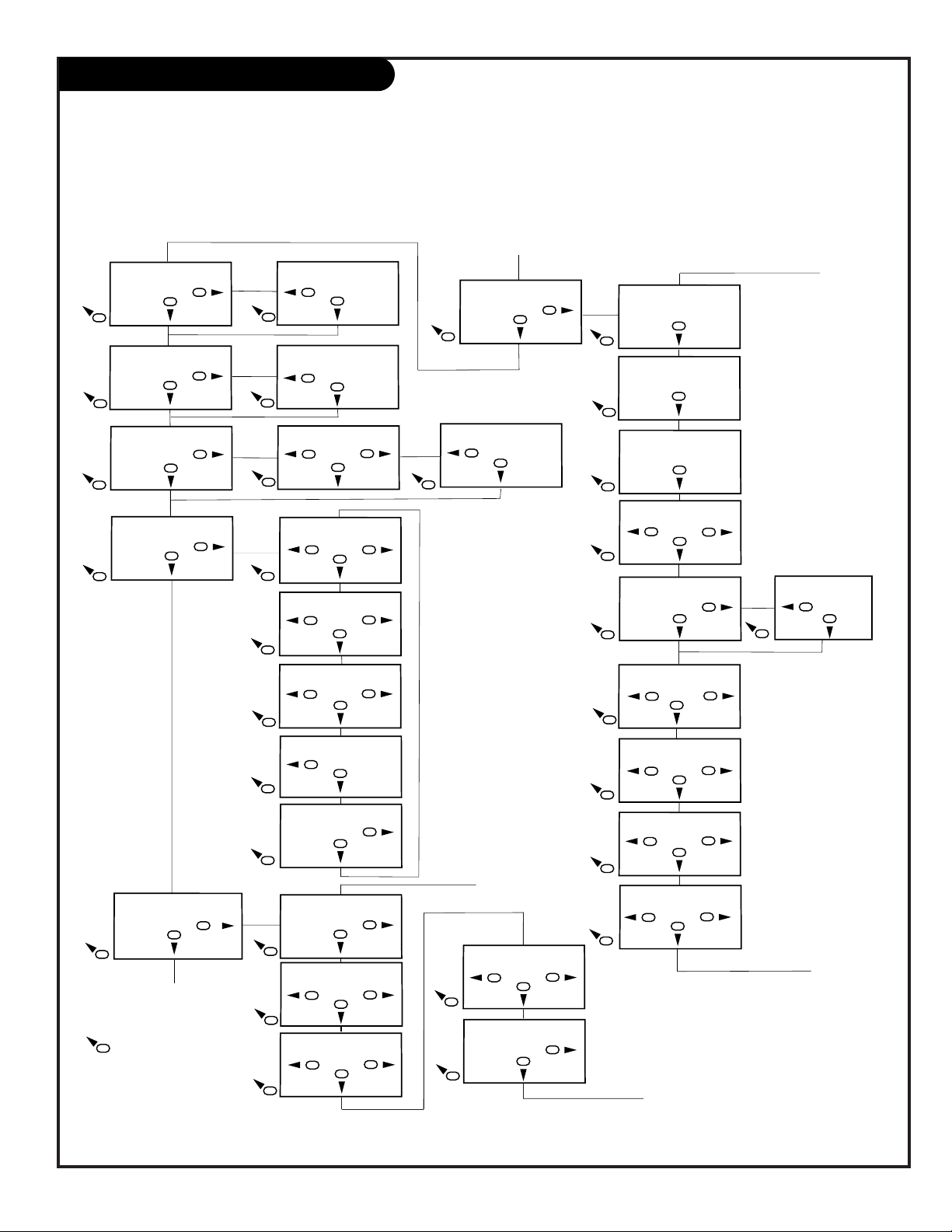
PAGE 15
206-3492-A
Menu Manual Set:
VGA Bot/4: 157
4
6
Adjust
8
Menu Manual Set:
VGA Store 0
6
Adjust
8
Menu Advanced:
SW 18 HW 6, 5
Adjust
8
Menu Advanced:
Total Lines 628
Adjust
8
Menu Advanced:
Vert. Freq 60
Adjust
8
5
5
5
5
5
Menu Adjust:
Advanced . . .
6
Adjust
8
5
5
Pressing this key will
exit all Scan Card
Menus.
Menu Size:
Out H-Center:77
6
Adjust
8
4
6
Adjust
8
4
6
Adjust
8
5
5
5
Menu Adjust:
H. SoftenOn
Adjust
8
Menu Adjust:
Zoom Cont. Menu
4
Adjust
8
Menu Adjust:
Zoom Level 3
4
6
Adjust
8
5
5
5
Menu Adjust:
H. SoftenOff
6
Adjust
8
Menu Adjust:
Zoom Cont: Remote
6
Adjust
8
Menu Adjust:
Zoom Level 2
6
Adjust
8
5
5
5
Menu Adjust:
Zoom Level 4
Adjust
8
Menu Adjust:
Screen Size . . .
6
Adjust
8
5
5
Menu Size:
Out V-Height: 600
4
Adjust
8
Menu Size:
Store OK
6
Adjust
8
Menu Manual Set:
VGA Left: 0
6
Adjust
8
Menu Manual Set:
VGA Width: 80
4
6
Adjust
8
Menu Manual Set:
VGA Top/4: 5
4
6
Adjust
8
5
5
5
5
5
Menu Adjust:
Manual Set . . .
6
Adjust
8
5
Menu Advanced:
Clock Width B: 2
6
Adjust
8
Menu Advanced:
Store Settings 0
4
6
Adjust
8
Menu Advanced:
Eng Reset Off
4
6
Adjust
8
5
5
5
Menu Advanced:
Sense 2
6
Adjust
8
Menu Advanced:
CR Character13
4
6
Adjust
8
Menu Advanced:
Clock width 2
4
6
Adjust
8
5
5
5
Menu Advanced:
CR character 130
Adjust
8
5
4
4
4
Menu Size:
Out H-Width:99
Menu Size:
Out V-Center:340
4
A
A
B
B
C
C
4
Remote Key Command Functions
Note: The following only applies to those TVs equipped with
PCZ Scan Conversion technology.
The table below illustrates the menu structure for your
Presentation TV while in Computer mode. As with the Remote
Key Command Functions, menus are operated through the
NUMBER keypad. Generally speaking, keys 4 and 6 adjust menu
options, key 8 cycles through menus and key 5 cancels all
operations no matter what menu you are adjusting. Although
menus are available in the Advanced mode, adjustments in
this mode should only be made by a qualified service representative.
Page 16

PAGE 16
206-3492-A
Auto Program (Channel Search)
Use Auto Program to specify Antenna or cable service
incoming signal source and automatically store all of the
channels that are found by channel search
With the remote control in hand, press the POWER key to
turn on the Presentation TV.
Press the MENU key so the Setup menu appears.
Using the UP arrow on the remote control, highlight Auto
Program on the screen.
Press a Right or Left arrow to go to the Auto Program
menu.
Using the UP arrow, choose either Cable TV or Off-Air
Antenna on your screen.
Press a Right or Left arrow to begin the Channel Search.
Press ENTER when finished.
1
2
3
4
5
6
7
PRG
POWER
CABLE
VCR
AUX TV
SURF
ENTER
FLASHBK MUTE
CHANNEL
CHANNEL
VOLUME VOLUME
123
456
7
0
89
MENU
REWIND FFWD
RECORD
QUIT
A
B
C
CC
TV/VCR
SOURCE
PAUSE TIMER
PLAY
STOP
3/5
AUTO PROGRAM
ADD/DEL/BLNK
CH. LABELS
CLOCK SET
ALARM MENU
LANGUAGE
TO PROGRAM
Mini glossary
OFF-AIR-ANTENNA If only over-the-air broadcasts are available, select Antenna.
CABLE If you subscribe to a cable service, select Cable.
Note: Auto Program finds channels being received by the TV
tuner.
Cable will not work unless you subscribe to a cable service.
4/6
1
7
2
Page 17

PAGE 17
206-3489-O
Front Panel Controls/Source Inputs
adjust select menu
L audio R
video in
reset
captions volume channel power
1
3
To access the menus press the MENU button
on the control panel. Cycle through the various menus by pushing the button repeatedly.
Press the SELECT button repeatedly to highlight the option you want to modify.
Press either the Right or left ADJUST button
to modify the selected option.
The menu will disappear after a few seconds.
Using the front control panel to access the menus
1
2
3
4
The Front Audio/Video jacks are a direct source
connection. If you have a device plugged into the
front Video jack, you will not be able to change
channels until you have unplugged the front
Video jack.
2
There are three jacks on the front of the Presentation TV
that make connecting Audio/Video devices like camcorders
very simple.
To use the front jacks as the signal source, simply plug a
composite video cable into the VIDEO jack. The TV will
automatically change its source setting to CAMPORT, as
indicated on the channel selection screen.
Left/Right Audio
Used for stereo sound from
various types of equipment.
Video
Connects the
video signals
from any
piece of
equipment.
Typical Front Panel Controls
Front
Computer
Connector
Used for 800 x
600 60Hz SVGA
type computer
hookup.
Reset
Used in conjunction with
the Clone
Programmer
Page 18

PRG
POWER
CABLE
VCR
AUX TV
SURF
ENTER
FLASHBK MUTE
CHANNEL
CHANNEL
VOLUME VOLUME
123
456
7
0
89
MENU
REWIND FFWD
RECORD
QUIT
A
B
C
CC
TV/VCR
SOURCE
PAUSE TIMER
PLAY
STOP
PRG (PROGRAM)
Programs remote to operate other
products.
FLASHBK (FLASHBACK)
Return to the last channel viewed.
POWER
Turns TV On or Off
.
CABLE/VCR/AUX/TV (MODE KEYS)
Switches remote mode to control other
devices. AUX is for optional devices.
CHANNEL (UP/DOWN)
Flip through available channels.
MUTE
Turns sound Off and On
while the picture remains.
ENTER
Shows the Channel/Time
display. Press after channel numbers for
instant selection.
NUMBER KEYPAD
Selects channels directly and enters numeric
values for some options
.
MENU
Displays on-screen menus for TV mode.
UP ARROW
The Up arrow selects menu options.
TIMER
Displays the Sleep Timer Menu.
VOLUME LEFT/RIGHT
Adjusts the sound levels on your
Presentation TV.
QUIT
Not functional.
TV/VCR-SOURCE
Switches between watching TV through
your antenna/cable source, composite
video source, S-VHS source, or any
Computer source.
Keys dedicated to VCR
functions will still operate your
VCR while the remote is in TV
mode.
The DOWN arrow key is reserved
for FM/TV on other models.
CC (CLOSED CAPTIONING)
Displays the closed captions/text menu.
LEFT/RIGHT ARROWS
The Left/Right arrows adjust menu options.
LED INDICATOR LIGHT
Lights when keys are pressed.
SURF
Access Channel preview and sources menu.
PAGE 18
Remote Key TV Mode Functions
206-3492-A
remote control part number
MBR3447
124-233
Page 19

PAGE 19
206-3492-O
On-Screen Menus/Displays Overivew
ON-SCREEN MENUS
SETUP MENU Adjusts the basic characteristics of the TV
Auto Program 16 Automatically finds and stores active channels to scroll through using Channel Up/Down.
Add/Del/Blnk 20 Manually picks and chooses which active channels will appear when using Channel Up/Down
Channel Labels 21 Labels your channels with their network names (ABC, CBS, HBO, etc.).
Clock Set 23 Sets the time.
Alarm Menu 24 Sets the time the TV will automatically turn itself on.
Language 25 Picks the language the on-screen menus will appear in.
AUDIO MENU 26 Customizes the sound. The options are:
Bass, Treble, Balance, Audio Mode, Front Surround, SoundRite, Speakers.
VIDEO MENU 27 Adjusts the picture for any viewing situation. The options are: Contrast, Brightness, Color,
Tint, Sharpness, Color Temp, Picture Pref.
PARENTAL 28 Allows user to block any channel or A/V source for up to 99 hours, with the use of a password.
CONTROL MENU
OTHER MENUS AND ON-SCREEN DISPLAYS
Source 30 Selects between available viewing sources; press TV/VCR/SOURCE.
Channel/Time 30 Shows the current time, channel, video and type of incoming audio signal, or mute.
Alarm 30 Sets the wake-up time; in Setup menu.
Sleep Timer 30 Sets the time the TV will turn off; press TIMER.
Volume 30 Shows current sound level; press VOLUME Up/Down.
Captions/Text 30 Use to select Caption/Text options; press CC.
Ch Preview 30 Displays the available channels list; press SURF.
Installer Menu 31 Shows operation adjustment levels and settings (for installer use).
SERVICE MENUS See Service Manual
Descriptions of the menus and displays
Using the MENU key and other keys indicated on the remote, the user can access the menus and displays described below.
Menu Name Page Description
Page 20

PRG
POWER
CABLE
VCR
AUX TV
SURF
ENTER
FLASHBK MUTE
CHANNEL
CHANNEL
VOLUME VOLUME
123
456
7
0
89
MENU
REWIND FFWD
RECORD
QUIT
A
B
C
CC
TV/VCR
SOURCE
PAUSE TIMER
PLAY
STOP
PAGE 20
206-3492-A
Fine-tune the channel selection list
Setting Add/Delete/Blank
Press the MENU key on the remote so the Setup menu
appears.
Press the UP arrow repeatedly to highlight the
Add/Del/Blnk option.
Using either the NUMBER keypad and ENTER or the Channel
Up/Down arrows on the remote, select a channel. (If
adding a deleted channel, you will need to use the
NUMBER keypad and ENTER.)
Using the Right or Left arrow, choose whether that channel
is Added, Deleted, or Blanked.
To continue, select another channel and repeat Step 3.
When you are finished, press ENTER to remove menu.
1
2
3
4
5
2
AUTO PROGRAM
ADD/DEL/BLNK
CH. LABELS
CLOCK SET
ALARM MENU
LANGUAGE
CH 44 ADDED
Mini glossary
ADD Adds new channels to the list that the user can scroll through when using the remote.
DELETE Removes channels for one reason or another from the list that the user can scroll through.
BLANK Removes the video and audio signal from a channel.
4
5
If you delete a channel, it isn’t gone for good. Just select it
using the NUMBER keypad on the remote, or add it later.
3
3
1
Page 21

PRG
POWER
CABLE
VCR
AUX TV
SURF
ENTER
FLASHBK MUTE
CHANNEL
CHANNEL
VOLUME VOLUME
123
456
7
0
89
MENU
REWIND FFWD
RECORD
QUIT
A
B
C
CC
TV/VCR
SOURCE
PAUSE TIMER
PLAY
STOP
PAGE 21
206-3492-A
Using Preset Channel Labels
Customizing channel names with the Preset Channel Labels
(Or, see the next page to create your own custom channel
labels)
Using either the NUMBER keypad or the Channel
Up/Down arrows on the remote, select a channel.
Press the MENU key on the remote so the Setup menu
appears.
Choose the Ch Labels option using the UP arrow.
Pressing either the Right/Left arrow repeatedly, pick the
label you want from the available selections;
such as A & E.
To continue channel labeling, select another channel or
if you are finished, press ENTER to remove menu.
1
2
3
4
3
AUTO PROGRAM
ADD/DEL/BLNK
CH. LABELS
CLOCK SET
ALARM MENU
LANGUAGE
CH 32 FOX
Mini glossary
- - - - The 4 dashes will allow a channel label to appear; if one is provided by the broadcaster.
NONE Prevents any channel label from appearing.
LAB 1, Are the 20 programmable labels. These 20 labels can be customized with 5 characters spaces available for each label.
thru LAB 20,
4
5
2
Some channels already provide a channel label which is included
with the broadcast signal.
Labeling the channels helps the identify which familiar nationwide
channels are available. i.e., A & E -Arts and Entertainment, CNN News, ESPN - Sports, HBO - Movies and so on...
1
1
5
1
Page 22

PAGE 22
206-3492-A
Creating Your Own Channel Labels
PRG
POWER
CABLE
VCR
AUX TV
SURF
ENTER
FLASHBK MUTE
CHANNEL
CHANNEL
VOLUME VOLUME
123
456
7
0
89
MENU
REWIND FFWD
RECORD
QUIT
A
B
C
CC
TV/VCR
SOURCE
PAUSE TIMER
PLAY
STOP
Customize channel names by using your own custom channel labels
To Program a Channel Label
First select a channel using the NUMBER keypad and ENTER or
the Channel Up/Down arrows, on the remote control.
(To select a deleted channel, use the NUMBER keypad and
ENTER.)
To program a channel label, press MENU to go to the Setup
menu and select CH LABELS.
Press the Right/Left adjust arrow to scroll the available preset
labels. Scroll past - - - -, scroll past NONE, to go to the first
programmable label slot, LAB 1 (Label 1). Notice that the
label appears with the title LAB 1, and is also on a dark background; which will distinguish it from the preset labels.
Operating the Custom Labels Menu
Use Volume Up/Down to select the first letter.
a. Press MUTE to clear the label if necessary.
Use Channel Up/Down to scroll through and change the character to one of the 255 characters available.
Repeat Steps 4 and 5 to set characters for the other character
spaces available on the label.
Press ENTER to remove menu when finished.
Menu Operation Notes:
Adjust Left/Right Switches to the next label.
- - moves to the next or previous
label.
Volume Up/Down Selects character spaces
- - moves to the next or previous
character space.
MUTE Removes current label,
- - if first character space is
selected.
Channel Up/Down Scrolls through the available
characters.
ENTER Accept the channel label and
removes the menu.
1
2
3
4
3
AUTO PROGRAM
ADD/DEL/BLNK
CH. LABELS
CLOCK SET
ALARM MENU
LANGUAGE
CH 30 CNN-2
3
6
4/A
1/5
5
1/5
4
4
Mini glossary
- - - - The 4 dashes will allow a channel label to appear; if one is provided by the broadcaster.
NONE Prevents any channel label from appearing.
LAB 1, Are the 20 programmable labels. They can be customized for your needs with 5 characters spaces available on each label.
thru LAB 20,
6
2
Page 23

PRG
POWER
CABLE
VCR
AUX TV
SURF
ENTER
FLASHBK MUTE
CHANNEL
CHANNEL
VOLUME VOLUME
123
456
7
0
89
MENU
REWIND FFWD
RECORD
QUIT
A
B
C
CC
TV/VCR
SOURCE
PAUSE TIMER
PLAY
STOP
PAGE 23
206-3492-O
The Sleep Timer may be instantly set by pressing the TIMER key
repeatedly. when you have made your selection, press ENTER to
set the timer and return to TV viewing.
The On/Off timer will not work until the Clock on your television
has been set.
Set the Clock
Set the clock on the Presentation TV
1
2
3
4
AUTO PROGRAM
ADD/DEL/BLNK
CH. LABELS
CLOCK SET
ALARM MENU
LANGUAGE
10:32 AM
TIMER
1
4
2
3
With the Setup menu on screen, use the Up arrow to highlight the Clock Set option as shown.
Set the current time; use the NUMBER keypad to enter the
hours, then minutes. For example, enter 06, then 30, to set
6:30 on the clock.
Use the TIMER key to specify AM or PM.
Press ENTER to start the clock and return to TV viewing.
Mini glossary
TIME A four-digit figure broken down into hours and minutes, that is used to enter the current time when setting the clock or on/off timer.
HOURS First two digits that are entered when setting the clock, or the on/off timer.
MINUTES The last two digits that are entered when setting the clock, or the on/off timer.
Page 24

PRG
POWER
CABLE
VCR
AUX TV
SURF
ENTER
FLASHBK MUTE
CHANNEL
CHANNEL
VOLUME VOLUME
123
456
7
0
89
MENU
REWIND FFWD
RECORD
QUIT
A
B
C
CC
TV/VCR
SOURCE
PAUSE TIMER
PLAY
STOP
PAGE 24
206-3492-O
Set a time in the
Alarm menu to turn
the TV on
With Alarm Menu highlighted in the Setup menu, press the
Left/Right arrow go to the menu.
Using the NUMBER keypad, set the time you want the TV to
turn on. For example, to set 7:30 AM, press 0, 7, 3, 0.
Use TIMER to pick AM/PM.
Press ENTER to remove menu.
The alarm will only work if the TV is turned off.
1
2
3
4
Setting the Wake Up Alarm
AUTO PROGRAM
ADD/DEL/BLNK
CH. LABELS
CLOCK SET
ALARM MENU
LANGUAGE
TO SET ALARM
2
1
4
3
Page 25

PRG
POWER
CABLE
VCR
AUX TV
SURF
ENTER
FLASHBK MUTE
CHANNEL
CHANNEL
VOLUME VOLUME
123
456
7
0
89
MENU
REWIND FFWD
RECORD
QUIT
A
B
C
CC
TV/VCR
SOURCE
PAUSE TIMER
PLAY
STOP
PAGE 25
206-3492-O
Language
AUTO PROGRAM
ADD/DEL/BLNK
CH. LABELS
CLOCK SET
ALARM MENU
LANGUAGE
ENGLISH
2
1
4
Choose the language for the on-screen menus
Press the MENU key on the remote control so the Setup
menu appears.
Use the UP arrow on the remote control, to highlight
Language on your screen.
Press a Left/Right arrow to choose one of the following
options: English, Spanish or French.
Press ENTER to return to TV viewing.
1
2
3
4
3
Page 26

PRG
POWER
CABLE
VCR
AUX TV
SURF
ENTER
FLASHBK MUTE
CHANNEL
CHANNEL
VOLUME VOLUME
123
456
7
0
89
MENU
REWIND FFWD
RECORD
QUIT
A
B
C
CC
TV/VCR
SOURCE
PAUSE TIMER
PLAY
STOP
PAGE 26
206-3492-O
Mini glossary
STEREO SOUND Stereo (stereophonic) sound refers to audio that’s divided into right and left sides.
MONO SOUND Mono (monaural) sound is one channel of sound. On more than one speaker, all the speakers play the same audio.
Adjust the audio options
1
2
3
4
Not all programming is broadcast in stereo sound or has 2nd
Audio SAP.
Audio Menu
Press the MENU key repeatedly on the remote control
until the Audio menu appears.
Using the UP arrow on the remote control, highlight
the audio option you want to change. Choose from:
• Bass: Increases/decreases lower-end sounds.
• Treble: Increases/decreases higher-end sounds.
• Balance: Allows you to put the sound more to the
left or right channel.
• Audio Mode: Choose from Stereo sound, Mono, or
2nd Audio/SAP.
• SoundRite: Turns the uniform volume feature on or
off.
• Front Surround: Turns front surround on or off.
• Speakers: Turns the TV speakers on or off.
Press a Left/Right arrow to adjust or change the
option you have selected.
Press ENTER to return to TV viewing, or press the UP
arrow and return to the Audio Menu to adjust another
option.
FRONT SURROUND
2/4
1
4
3
Page 27

PAGE 27
206-3492-O
PRG
POWER
CABLE
VCR
AUX TV
SURF
ENTER
FLASHBK MUTE
CHANNEL
CHANNEL
VOLUME VOLUME
123
456
7
0
89
MENU
REWIND FFWD
RECORD
QUIT
A
B
C
CC
TV/VCR
SOURCE
PAUSE TIMER
PLAY
STOP
Video Menu/Computer Video Menu
Note: For Computer Video menu, select a computer source.
Press the MENU key repeatedly until the Video menu
appears. Your options are:
• Contrast: Adjusts the level of difference between white
and black in the TV picture. The more contrast, the
brighter the picture appears.
• Brightness: Increases or decreases amount of white in
the TV picture.
• Color: Adjusts levels of all colors in the TV picture.
• Tint: Adjust the relative amounts of the color red and
green in your picture.
• Sharpness: Raise or lower the definition of the picture.
The lower the level, the softer the image will appear.
• Picture Preference: Choose either Custom or Preset.
Custom allows you to set the picture the way you want.
Preset moves all the above options back to their original,
factory-set levels.
• Red/Green/Blue: Adjusts level of color in the picture.
• HORZ Position: Adjusts horizontal position of picture.
• VERT Position: Adjusts vertical position of picture.
Using the UP arrow on the remote control, choose Contrast
on your screen.
Using a Left/Right arrow, change the contrast level to your
preference.
Press ENTER, to return to TV viewing, or repeat from step
two to set the other menu options.
Use the UP arrow to choose Picture Preference on your
screen.
Use the Left/Right arrow, to choose either the original settings with Preset, or use your own settings with Custom.
1
2
3
4
5
Choose the Preset option in Picture Preference to quickly reset the
levels to their original values.
Use either the TV Video menu for TV
sources or the Computer Video menu
for Computer sources to customize the
picture image
CUSTOM
CONTRAST
BRIGHTNESS
COLOR
TINT
SHARPNESS
PICTURE PREF
1
4
3/6
6
2/5
CONTRAST
BRIGHTNESS
RED
GREEN
BLUE
HORZ POSITON
VERT POSITION
PICTURE PREF
COMPUTER VIDEO MENU
PRESET
Page 28

PAGE 28
206-3492-A
Parental Control Menu
Mini glossary
MOTION PICTURE ASSOCIATION OF AMERICA (MPAA) RATING SYSTEM
G General Audiences Content not offensive to most viewers.
PG Parental Guidance Content is such that parents may not want their children to view the program.
Suggested
PG-13 Parental Guidance Program is inappropriate for preteens, with a greater degree of offensive material
Suggested than a PG rated program.
R Restricted viewing Not for children under age 17. Strong elements of sex and/or violence.
NC-17 Restricted Viewing Not for children under age 17 under any circumstances. Strong sexual content.
X Hard Core Films Same as NC-17 rating.
Note: Zenith Electronics Corporation is not liable for any program content that appears when using this rating system; as always, user
discretion is advised.
Overview
To insure complete coverage for all TV programs, (movies and regular TV shows) choose a rating for MPAA, from the selections below AND choose ratings from the TV Parental Guidelines Rating System on the next page, using the Age Block
option for General Audiences, and for Children. In addition to those, you may wish to add additional restrictions from the
Content Block menu. See the Parental Control menu, and submenus example on the next page.
Things to Consider before Setting Up Parental Control
Determine which rating you consider acceptable to the viewer. (For example, if you choose TV-PG, all more restrictive ratings will be automatically blocked; the viewer will not be able to see: TV-PG, TV-14, or TV-MA rated programming.)
Do you want to block the auxiliary video source entirely? (Blocks the signal sent by the equipment, such as a VCR, connected to the TV Audio/Video input jacks; in the Aux. Block option.) Or leave unblocked, then choose allowable ratings.
Block program “Content” based on individual parameters such as: Strong Dialog, Bad Language, Sex Scenes, Violence
Scenes, or Fantasy Violence Scenes; in the Content Blk option.
How many hours do you want Parental Control to be active? You can set the Hours option for up to 99 hours.
Select a secret password; in the Set Password option. Use the number keys on the remote. Don’t forget the password, it is
the only way you can access the Parental Control menu and change rating selections, or turn Parental Control off.
Do you want Parental Control to be active all the time? If not, you can turn it on or off; with the Lock On/Off option.
If used, this optional feature can “block” undesirable programming from appearing on the TV.
Note: Parental Control is not available in Computer Mode. To block Computer inputs, use the block AUX
SOURCES option in the Parental Control menu in TV Mode; computer inputs will not be available.
You can set different Parental Control viewing restrictions for general audiences and for children - - both can
be active at the same time
.
Simply specifying one content block such as Sex Scenes,
will not automatically block another content in the programs from appearing.
Even if you choose to leave the Aux inputs unblocked, the
ratings you specify will automatically restrict the programming that appears from the video sources.
You cannot disable Parental Control by disconnecting the TV
from power. Block hours will automatically reset to the original block time setting specified if power is disconnected.
Parental Control offers the user a wide variety of options and settings that restrict or “block” the programming that can
appear on the TV. Parental control allows the user the capability of defining which program rating they consider acceptable, to the younger or more sensitive viewer. It can be preset and turned either on or off by the user who specifies the
secret 4-number code, the password. The number of hours blocked are specified. General audience and children viewer
blocks should both be programmed into the TV’s memory. Viewer ratings are specified for both TV and the motion picture
industry; both rating systems should be used, for complete coverage. The ratings are based on the ages of children.
Page 29

PRG
POWER
CABLE
VCR
AUX TV
SURF
ENTER
FLASHBK MUTE
CHANNEL
CHANNEL
VOLUME VOLUME
123
456
7
0
89
MENU
RECORD
QUIT
A
B
C
CC
TV/VCR
PAUSE TIMER
PAGE 29
206-3492-O
Parental Control Menu
Mini glossary
TV PARENTAL GUIDELINE RATING SYSTEM
TV-G General Audience Considered suitable for all audiences; children may watch unattended.
TV-PG Parental Guidance Suggested Unsuitable for younger children, may contain: Suggestive Dialog, Bad Language, Sex, and Violence Scenes.
TV-14 Parents Strongly Cautioned Unsuitable for children under 14, may contain: Strong Dialog, Bad Language, Sex, and Violence Scenes.
TV-MA Mature Audience Only Adults only, may contain: Strong Dialog, Bad Language, Sex, and Violence Scenes.
CHILDREN’S CLASSIFICATIONS
TV-Y Children Considered suitable for all children under 7 years old.
TV-Y7 Children 7 and over Considered suitable for children over 7, may contain Fantasy Violence Scenes.
As shown above, with the Parental Control menu
on-screen, use the UP arrow to highlight an option
like Content Block, then press the Right arrow.
Use the Up/Left/Right arrows to select and adjust
or set the rating for an option. For Sex Scenes for
example, use the “From TV-PG” setting. (See the
Mini Glossary, Ratings Charts on this and the previ-
ous page for rating definations.)
After you have selected and adjusted the parental
control menu options to your preferences:
- Set the hours you want Parental Control active.
- Set a 4-number password.
- Set the Lock On/Off option to either on or off.
Note: No Rating means the broadcast does not include rating
information. You can choose to block broadcasts without rat-
ing data.
After you have read the preceding page, follow instructions below to set up and activate Parental Control
DIALOG
LANGUAGE
SEX SCENES
VIOLENCE
F VIOLENCE
NO CONTENT
TO BLOCK
TO BLOCK
GENERAL
CHILDREN
AGE BLOCK
UNBLOCKED
CONTENT BLOCK
2/3
2/3
1
2
3
4
Page 30

PAGE 30
206-3492-O
Other Menus & On-Screen Displays
CH 9
3:12
PM
STEREO
Channel/Time/Audio Display
Press ENTER. Shows currently
selected channel or source, current
time if the clock has been set, and
incoming audio signal.
Sleep Timer Menu
Press TIMER. Shows remaining time
before TV shutoff.
Volume Display
Press VOLUME. Shows currently
selected sound setting.
Ch Preview Menu
Press SURF. Displays list of the
available TV Channels, Parental
Control menu and Video Channel
access.
Closed Captions Menu
Press CC. Shows Caption/Text
options: Off, Caption 1, Caption 2,
Caption 3, Caption 4, Text 1, Text
2, Text 3, or Text 4.
Alarm Menu
Press ALARM. Sets the time the TV
will turn itself on.
CHANNEL PREVIEW
5 - - - 9 - - - 20 - - - 32 - - - 44 - - - 66 - - - -
CH TO SELECT, ENTER TO QUI
CC FOR PARENTAL CONTROL
VOLUME
Press the remote keys indicated below to access these menus and displays
Source Menu
Press TV/VCR SOURCE. Gives access
to the other available sources:
Antenna/Cable, Camport, Aux
Video, S-Video, Front Computer
SVGA, Rear Computer SVGA, and
Rear Computer NTSC.
SOURCE
ANTENNA/CABLE
PRESS:
SOURCE TO CHANGE
ENTER TO ACTIVATE
CAPTIONS
CC
PRESS CC
Page 31

PAGE 31
206-3492-A
Accessing the Installer Menu
The Installer menus are accessed by using the remote control. Just press
and hold MENU (about 8 seconds) until the display changes, then press 9,
8, 7, 6, then ENTER. To exit the Installer Menu, press ENTER again. Any
changes you make will be stored in nonvolatile memory.
The Installer Menu opens with item 03 VERT POS. Press the Up/Down arrow
keys to sequence through the various items. Or, access an item directly by
entering the line number, then pressing MENU. For example, to access the
Start channel/volume feature which is on line 10, press 10, then MENU. To
change a current setting use the Left/Right ADJ keys.
Using the Installer Menu
Items 00-27 are immediately accessible only upon entering the Installer
Menu. Their numbers, descriptions, ranges, factory default settings, and a
place for listing any changes made on-site are given below. A second section of the Installer Menu that is intended for qualified service technicians
only is not shown (items 28-201). Normally these items do not require
adjustment.
Options in the Installer Menu:
Installer Menus
1391-00 01.19 V 01
03 VERT POS 15
XX/XX/9X TE11111111
Use the Installer Menus to make adjustments to operational settings
Installer should leave item 00 FACT MODE
set to 0 (default). Items 28-201 are ser-
vice-type adjustments and only qualified
technicians having specialized test equipment should access them.
Item Description Range Fact. Set Recommend. Setting
00 FACT MENU 0 - 1 0 Leave default set 0
01 PRESET PX* See note page 32 0 - 1 1
02 POWER MANAGE 0 - 7 0
03 VERT POS*See note page 32 0 - 30 15
04 HORZ POS* See note page 32 0 - 45 34
05 BAND/AFC 0 - 7 0
06 MIN VOLUME 0 - 63 0
07 MAX VOLUME 0 - 63 63
08 AC ON 0 - 1 0
9 KEY DEFEAT 0 - 1 0
10 STRT CH/VOL 0 - 255 255
11 HOSPITALMODE 0 - 2 0 Leave default set 0
12 CHAN LOCK 0 - 1 0
13 GHOST CH. 0 - 1 0
14 SCAN MODE 0 - 3 0 Leave default set 0
15 TEXT MODE 0 - 1 1
16 SLEEP TIMER 0 - 1 0
17 ALARM 0 - 1 0
18 CH. OVER RIDE 0 - 1 1
19 OLD OCV 0 - 1 0 Set to 1 for Spectramate Systems
20 CAPTION LOCK 0 - 1 0
21 FUNCTION PRE 0 - 1 0
22 FEATURE LEVEL 0 - 1 1 Leave default set 1
23 NTSC SCANCARD 0 - 1 1
24 STRT CH IN SM 0 - 1 0
25 V-CHIP 1 0 - 1 1
26 MAX BLOCK HRS 0 - 99 12
27 STRTAUX SRCE 0 - 6 4
Page 32

PAGE 32
206-3492-A
Installer Menus
*Note: Page 31, Page 32
Changing TV Mode Values Installer menu options: 01 PRESETPX (Preset Picture),
03 VERT POS (Vertical Position), and 04 HORZ POS (Horizontal Position), have
separate values for TV mode and Computer mode. If you enter the installer menu
with the source being a TV channel, Aux, S-Video, or Camport, you change the values for TV mode only.
Changing Computer Mode Values
To change values for Computer mode, press TV/VCR SOURCE to select REAR
COMPUTER SVGAor FRONTCOMPUTER SVGAas the source, then enter the
installer menu. The changes you make will then apply to Computer Mode.
00 FACT MENU (Factory Menu)
Used to access and customize Service Menu: settings using the
installer type remote.
01 PRESET PX (Preset Picture)*
Saves your custom video settings (color, tint, contrast, and
brightness) in nonvolatile memory (not affected by power loss).
Memory status is indicated by a 1 for “custom settings already
stored,” or 0 for “custom settings have not been stored.”
Make all custom video settings before you access the Installer’s
Menu: and PRESET PX. When you use the ADJUST keys to toggle
from 1 - 0, any changes in the video settings will be stored sure
they are correct! These settings become the PRESET values for the
PICTURE PREF option of the Video Menu. (For more information
refer to the Video Menu section of this manual.)
02 POWER MANAGE (Power Management)
The POWER MANAGE function is for saving energy. When set to 0,
Power Manage is OFF. Settings range from 0 - 7, with 1 - 7 representing the hours that the TV will remain on, unless there has
been activity from either the control panel or remote.
03 VERT POS (Vertical Position)*
Moves captions and displays vertically on the screen. Use the
Left/Right ADJUST arrows. Typical value is 15. Black bars top and
bottom define the active screen area.
04 HORZ POS (Horizontal Position)*
Moves captions and displays horizontally on the screen. Use the
ADJUST keys. Typical value is 34. Black bars top and bottom
define the active screen area.
05 BAND/AFC (Band/Automatic Frequency Control)
There are 8 possible settings for this option:
0 = Broadcast Fixed4 = Broadcast AFC
5 = CATV Fixed 1 = CATV AFC
6 = HRC Fixed 2 = HRC AFC
7 = ICC Fixed 3 = ICC AFC
Channels are accessed faster when fixed modes are used. The AFC
(search modes) should only be used when some channels are not
on nominal frequencies. NOTE: BAND is automatically set by AUTO
PROGRAM.
If some channels were not found by AUTO PROGRAM, select the
appropriate AFC setting here and add the channels using the
ADD/DEL option in the Setup Menu.
06 MIN VOLUME (Minimum Volume)
This function determines the minimum volume level allowable
with the VOLUME (VOL) Up/Down control. In this way, for example, someone cannot set the volume too low to hear. The range is
from 0 to 63—change values with ADJUST . The factory default is
0, which provides full range of volume control. It may be best to
set the same value on every TV. NOTE: The minimum volume level
cannot have a value setting higher than in the MAX VOLUME level
(described below).
07 MAX VOLUME (Maximum Volume)
This function determines the maximum volume level allowable
with the VOLUME VOL Up/Down control. In this way, for example,
someone cannot set the volume level high enough to disturb others. The range is 0 to 63, with 63 as the default which gives the
patient the full range of volume control. Change values with
ADJUST keys. It may be best to set the same value on every TV.
NOTE: The maximum volume level cannot have a value setting
lower than the MIN VOLUME level (described above).
08 AC ON (AC Power Switchable)
Allows the TV to turn ON just by applying AC power. Pressing the
ON button is not necessary. This is desirable when the TV is
plugged into a cable box or a power outlet controlled by a wall
switch. Use ADJUST to select 0 or 1, where 0 is the default is
OFF, and 1 is ON.
NOTE: When set to 1 (ON), the TV does not respond to ON/OFF
commands from either the remote or the control panel, and the
SLEEP TIMER is also nonfunctional.
9 KEY DEFEAT (Keyboard Defeat)
When set to 1, it prevents the end user from accessing screen
menus on the front panel—MENU, SELECT, and ADJUST do not
function. When set to 0, those keys are functional. The menus can
always be accessed with MENU on the remote.
10 STRT CH/VOL (Start Channel/Volume)
When active, this function allows you to determine the initial volume level setting and channel number when the TV is turned ON.
This feature is useful for an in-house information channel, since
the TV would always select that channel when it is turned on.
When inactive, the volume level and channel retain the settings
when the set was last used.
The range of values is 0 - 255.
Use the Left/Right Adjust arrow keys to choose:
Setting “1” With number 255 selected, the feature is inactive.
(When the TV is turned on, the Volume level and Channel number
will be the same Volume level and Channel number that were
selected before the TV was turned off.)
Setting “2” Other numbers determine the start-up (turn on)
channel.
Page 33

PAGE 33
206-3492-A
Installer Menus
Use the Installer Menus to make adjustments
Setting “3” Set the volume level as desired before “entering” the
Installer Menu.
11 HOSPITAL MODE
Not used in Presentation-series TVs. Leave at default setting 0.
12 CHAN LOCK (Channel Lock)
When set to 1 the CHAN LOCK is ideal if a cable box (or similar) is
the sole source for programming—and the TV must always be on
the same channel. Changing channels with the Channel up/down or
or keypad numbers is impossible. Channel Lock is inactive when set
to 0 (default).
Generally, this feature is used in connection with START CHAN/VOL
(line 11) where the start channel may, for example, be set to 3 or
4. If the start channel is 3 then the TV will remain on channel 3.
NOTE: When channel lock is active AUTO PROGRAM and CH.
ADD/DEL in the SETUP MENU are not active.
13 GHOST CH. (Ghost Channel)
When set to 1, the current channel number is displayed in the
upper right corner of the CRT. The number moves slightly to prevent damage to the screen. The default is “0” or OFF. NOTE: When
captions are on, the “ghost channel” is not displayed.
14 SCAN MODE
Allows variation in setting the On/Off with Channel UP/DOWN. You
may opt for TV channels only; TV channels + Off/ON in Scan Mode:
Scan mode Characteristics
0 Channel up/down keys change channels only.
1 Channel down below the lowest
channel (or channel up higher than
the highest) and TV turns off.
15 TEXT MODE
Determines whether TEXT 1, TEXT 2, TEXT 3, or TEXT 4 decoding is
enabled when TEXT is turned on (either from the Setup Menu or
directly with CC on the remote).
TIP: Set Text Mode to 1 only if text is offered in your video system.
16 SLEEP TIMER
When set to 1, the SLEEP TIMER feature may be used (but no message is displayed prior to turn-off). When set to 0, the sleep timer
is not available.
17 ALARM
Gives you the option of making the alarm function available to the
end-user. Set to 1, alarm function is available. Set to 0 to withhold
this function. (The clock must be set in order to use the alarm.)
18 CH. OVERRIDE (Channel Override)
When set to 1, the user is allowed to select channels with either
Channel up/down or by direct keypad entry. When set to 0, only
those channels that are entered for scanning may be selected.
19. OLD OCV (On Command Video)
Set to 1 for operation with “SpectraMate” systems from On
Command Corporation.
20. CAPTION LOCK
Set to 1 to restore previous caption On/Off state after TV turns off
when set to 0, captions are always off when TV is initially turned
on.
21. FUNCTION PRE
Set to 0 to suppress CHANNEL PREVIEW FUNCTION with some pay
per view systems.
22. FEATURE LEVEL
Default set to ZEN 1 for Zenith IR remote control operation. Set
O, P LBL for Zenith Private Label IR remote control operation.
23. NTSC SCAN CARD
Default set to 1, On. Set to 0 to turn off.
24. START CHANNEL IN SCAN MODE
Moves the power off function to the default turn-on channel picked
in Menu 10. (if Menu 14 is set to 1). For example, if you specified
channel 9 to be the default turn-on channel (Menu 10), repeatedly
pressing Channel up to scroll through the available channel list,
the TV will turn 0ff after the channel just prior to channel 9 is
selected and channel up is pressed again. Then, if you then press
channel up again, the TV will turn on, and tune to channel 9.
Notes:
Menu 10 allows you to specify a default tune-to channel, and vol-
ume level when the TV is tuned on.
Menu 14 allows you to specify whether:
The TV will remain on as the Channel up/down keys are pressed
repeatedly. or,
The TV will turn off when the highest/lowest channel is tuned.
Menu 24 allows you to move power off from the lowest/highest
channel in Menu 14 to the default turn-on channel number specified in Menu 10.
25. V-CHIP
Default set to 1, Parental Control active, 0=Parental Control off.
26. MAXIMUM PARENTAL CONTROL BLOCK HOURS
Default hours set to 12, default an be set up to 99 Hours.
27. START AUX SOURCE
Default is 4, Rear SVGA Computer. 0=Camport, 1=Aux. 2=S-Video.
3=Front SVGA Computer. 4=Rear SVGA Computer. 5=Rear NTSC
Computer. Use in conjunction with setting for Start Channel.
Note: The “Range” value indicated on page 31, of START AUX
SOURCE can be set to “0” only if the factory menu item
number 29 (AUTO CAMPORT) is set to “0”.
Page 34

PAGE 34
206-3492-O
A slow flashing green light indicates there is a problem with the communications between the TV and the programmer. In this
case, check for a damaged cable, poor contacts, or other connection troubles.
If the status indicator is red, the programmer batteries are low and should be replaced. Use 4 good quality alkaline AA batteries.
1
2
3
LT1500 QuickSet Programmer
Use the LT1500 QuickSet Programmer to duplicate the TVs setup
1
2
3
4
5
The optional QuickSet II Programmer (LT1500) allows custom setup and programming
information to be quickly copied from a master TV into multiple television sets. Once
learned from the master, setup data is retained in the LT1500 for future use and recall.
When using the LT1500, operation will be easier if the TV set is connected to a good
quality signal and operating with a stable picture displayed. To operate the LT1500, use
the indicated keys on an HP602, LP702, or MBR3447 remote, or the front panel keys on
the TV receiver.
Set up a master TV set using your remote and following the instructions in this operating guide. Set all features you wish to
customize including the channel scan list, channel labels, and service menu setups.
Connect the LT1500 to the master TV set using the cable provided with the programmer. Connect the cable between the MPI
jack on the TV and the programmer. Connecting the programmer to the TV set automatically activates the programmer powerswitching circuits.
Once connected, check the “Status Indicator” LED on the programmer. The indicator should be flashing a green double-blink
“heartbeat” pattern.
If communications are good, the sign-on screen will be displayed on the TV screen as shown on the quick setup instructions
which accompany the LT1500. If you intend to set the TV or programmer real-time clocks, note the clone clock and TV clock
time settings, then press a key to proceed to the main clone menu.
If you have previously stored a TV setup in a particular clone memory, it may be changed if desired by overwriting it with a
new setup. There is no need for a separate memory clear operation.
Item 1: Learn From TV
Setups stored in programmer memory are nonvolatile and will be retained even after a battery change.
Press (1) then ON/OFF, POWER, or ENTER to begin the learning process. Alternatively, use the TV front panel CHANNEL UP or
CHANNEL DOWN keys to highlight your choice, then press ON/OFF, POWER, or ENTER to activate.
The next screen will allow you to choose which of the available memories will be used to store this TV setup. With four memo-
ries available, four different TV setups can be stored in the LT1500.
Using the on screen menu, choose a memory or choose to return to the main selection menu, then press ON/OFF, POWER, or
ENTER to activate the selection.
The next screen gives you one last opportunity to check the versions of TV and clone setups. Press ON/OFF, or POWER to acti-
vate the learning cycle or any other key to return to the selection menu to make other choices.
Once the process has begun, the TV screen will display the ”LEARNING IN PROGRESS” message. Please wait until the process is
completed. When the TV screen displays “LEARNING COMPLETED”, press any key to end the learning process and return to the
clone selection menu.
Page 35

PAGE 35
206-3492-O
Clone Selection Menu Choices
1
2
3
4
5
6
1
2
1
2
1
2
3
Item 2: Teach to TV
Press (2) then ON/OFF, POWER, or ENTER to begin the teaching process. Alternatively, use the TV front panel CHANNEL UP or
CHANNEL DOWN keys to highlight your choice, then press ON/OFF, POWER, or ENTER to activate.
The next screen will allow you to choose which of the 4 available memories will be copied to this TV.
Press the desired memory number, then ON/OFF, POWER, or ENTER to begin the teaching process. Alternatively, use the TV
front panel CHANNEL UP or CHANNEL DOWN keys to highlight your choice, then press ON/OFF, POWER, or ENTER to begin.
Using the on screen menu, choose a memory or choose to return to the main selection menu, then press ON/OFF, POWER, or
ENTER to activate the selection.
The next screen gives you one last opportunity to check the versions of TV and clone setups . Press ON/OFF, or POWER to
activate the teaching cycle or any other key to return to the selection menu to make other choices.
The TV screen will show the ”TEACHING IN PROGRESS” message. Please wait until the process is complete. When the TV screen
displays “TEACHING COMPLETED”, press any key to return to the clone selection menu or unplug the clone cable if done.
Reset the TV: For the cloning to take effect, simply reset the TV by unplugging the TV set’s AC power cord for 5 seconds or
press the reset switch, using a straightened paper clip or toothpick, via the small access hole, located to the left of the front
SVGA computer input jack.
Item 3: Set Clone Clock From TV
To initially set the real time clock in the LT1500 or update the time, press (3), then press ON/OFF, POWER, or ENTER to copy
the current TV time to the clone clock. Alternatively, use the TV front panel CHANNEL UP or CHANNEL DOWN keys to highlight
your choice, then press ON/OFF, POWER, or ENTER to activate.
This process will return you to the sign-on screen to display the clone and TV clock settings. You may press a key to go to
the clone selection menu and perform other functions, or simply disconnect if time setting was your only task.
Item 4: Set TV Clock From Clone
To set the real time clock in the TV, press (4), then press ON/OFF, POWER, or ENTER to copy the current clone time to the TV
clock. Alternatively, use the TV front panel CHANNEL UP or CHANNEL DOWN keys to highlight your choice, then press ON/OFF,
POWER, or ENTER to activate.
This process will return you to the sign-on screen to display the clone and TV clock settings. You may press a key to go to
the clone selection menu and perform other functions, orsimply disconnect if time setting was your only task.
Item 5: Display TV Setup
Press (5) then ON/OFF, POWER, or ENTER to begin the teaching process. Alternatively, use the TV front panel CHANNEL UP or
CHANNEL DOWN keys to highlight your choice, then press ON/OFF, POWER, or ENTER to activate.
The TV screen will display the items in the service menu setups for you to observe. Use this function to quickly check a TV for
the correct setup.
Press any key to clear the display and return to the clone selection menu.
Use the LT1500 QuickSet Programmer to duplicate the TVs setup
7
Page 36

PAGE 36
206-3492-O
Clone Selection Menu Choices
1
2
3
4
5
Item 6: Display Clone Setup
Press (6) then ON/OFF, POWER, or ENTER to begin the teaching process. Alternatively, use the TV front panel CHANNEL UP
or CHANNEL DOWN keys to highlight your choice, then press ON/OFF, POWER, or ENTER to activate.
The TV screen will display the memory selection menu.
Press the desired memory number, then ON/OFF, POWER, or ENTER to display the contents of the selected memory.
Alternatively, use the TV front panel CHANNEL UP or CHANNEL DOWN keys to highlight your choice, then press ON/OFF,
POWER, or ENTER to begin.
The TV screen will display the items in the service menu setups for you to observe. Use this function to quickly check the
contents of a particular clone memory for the correct setup.
Press any key to clear the display and return to the clone selection menu.
Operation Notes
Disconnect the LT1500 from the TV set when you have completed the desired task. Disconnecting the clone automatically
switches it off. The real-time clock continues to run when the main circuits are switched off.
After replacing exhausted batteries, or if the programmer behaves strangely after a static shock, use a paper clip or similar
instrument inserted through the small hole marked ”RESET” to activate the internal reset switch and restore normal operation. After a reset, check the real-time clock setting. It may be necessary to reset the clock from a TV containing the correct time.
The LT1500 programmer is designed to be used with TV sets containing the 221-01006 and later processors. Use with earlier TV sets may give unpredictable results. The specific microprocessor used in any TV set may be determined by activating
the service menu. The microprocessor part number appears at the top of the screen when the service menu is activated.
Processors before the 221-01006-04 have a limited screen display capability. They can not display entire screens as shown
in the quick setup instructions accompanying the LT1500 programmer. Use the printed menu illustrations on the quick
setup sheet as an aid to making your programming choices.
Use the LT1500 QuickSet Programmer to duplicate the TVs setup
Page 37

PRG
POWER
CABLE
VCR
AUX TV
SURF
ENTER
FLASHBK MUTE
CHANNEL
CHANNEL
VOLUME VOLUME
123
456
7
0
89
MENU
REWIND FFWD
RECORD
QUIT
A
B
C
CC
TV/VCR
SOURCE
PAUSE TIMER
PLAY
STOP
PAGE 37
206-3492-O
The device you want to program should be ON.
On the chart in this manual, find the type of
device you’re programming and then find the
brand name. Make a note of the three-number
code—you’ll need it soon.
Press and hold the PRG key. It’s recessed so it
doesn’t get pushed accidentally. When the indicator light turns on, you can release the key.
Push the key with the name of the device you’re
programming (VCR, CABLE, AUX, TV).
Using the NUMBER keypad, enter the three-number code found on the chart in the Reference section.
Press ENTER to save the code The indicator light
will flash three times and turn off if the code was
accepted.
Aim the remote at the device and push the
POWER key. The device should turn off. If not, try
the other codes listed and continue from step
three.
Programming your Zenith remote will allow you to use
one remote to work up to 7 different devices!
Not all devices will work with your Zenith remote control.
1
2
3
4
5
6
7
3
Indicator Light
6
7
4
5
Programming the Remote
Program your remote to control a variety of A/V devices
Page 38

PRG
POWER
CABLE
VCR
AUX TV
SURF
ENTER
FLASHBK MUTE
CHANNEL
CHANNEL
VOLUME VOLUME
123
456
7
0
89
MENU
REWIND FFWD
RECORD
QUIT
A
B
C
CC
TV/VCR
SOURCE
PAUSE TIMER
PLAY
STOP
PAGE 38
206-3492-O
Amplifier Volume Override
2
5
3
4
Indicator Light
Mini glossary
AMPLIFIER An electronic device that amplifies sound from a television, CD player, VCR, or other A/V device.
1
2
3
4
Your volume and mute keys now control your amplifier,
while all the other keys still operate the Presentation
TV. To put everything back to normal, reprogram all
modes with their original codes (see the “Programming
Your Remote” section).
If you can’t find the code for your
amplifier, use the Auto Find feature.
5
Program the code that operates your amplifier
into the CABLE or AUX mode, as described on
the “Programming Your Remote” page.
Select the mode in which you want volume to
appear (e.g. TV, Cable, VCR, Aux, Aux 1, 2, 3).
Press and hold PRG on your remote until the
indicator light stays lit.
Press 4-9-9; then ENTER on the remote. The
indicator light will flash three times if code is
accepted.
Audio system volume/mute now appears in the
mode selected.
Sets up your amplifier to be operated in the Cable mode or one of the Aux
modes on the remote control
Page 39

PRG
POWER
CABLE
VCR
AUX TV
SURF
ENTER
FLASHBK MUTE
CHANNEL
CHANNEL
VOLUME VOLUME
123
456
7
0
89
MENU
REWIND FFWD
RECORD
QUIT
A
B
C
CC
TV/VCR
SOURCE
PAUSE TIMER
PLAY
STOP
PAGE 39
206-3492-O
AUX+1, AUX+2, AUX+3
Refer to the brand reference chart to find the
type and brand name of the device you're programming.
Press and hold the PRG key until the indicator
light turns on.
Press the AUX key and the 1 on the NUMBER
key pad at the same time (for AUX +1).
Using the NUMBER keypad, enter the threenumber code for the device you've selected.
Press ENTER to save the code.
Aim the remote at the device and press
POWER. It should turn off.
Repeat the steps to program AUX+2, and
AUX+3.
1
2
3
4
5
6
7
5
6
2
4
3
Programming your Zenith remote will allow you to
use one remote to work up to 7 different devices.
Some devices may not work with your Zenith remote
control.
Page 40

PRG
POWER
CABLE
VCR
AUX TV
SURF
ENTER
FLASHBK MUTE
CHANNEL
CHANNEL
VOLUME VOLUME
123
456
7
0
89
MENU
REWIND FFWD
RECORD
QUIT
A
B
C
CC
TV/VCR
SOURCE
PAUSE TIMER
PLAY
STOP
PAGE 40
206-3492-O
5/7
3
6
2
4
Indicator Light
Remote Control Auto-Find
Turn on the device you’re programming for the
remote control.
Press and hold the PRG key until the indicator light
turns on.
Press the key for the device you’re trying to program
(CABLE, VCR, AUX, TV).
Enter the code 0-0-0 (zero-zero-zero), then press the
ENTER key right away.
Aim the remote at the correct device and press
POWER. Allow a second to pass, then push the
POWER key again. Repeat until the device turns off.
(This is a trial and error process, so it may be necessary to repeat these steps until the remote finds your
code.)
Push ENTER to save the code.
Press POWER to turn the device back on.
1
2
3
4
5
6
7
You can quickly get out of Auto Find by pressing QUIT.
If the indicator light stays on while you push
Power, instead of turning off, all the codes
have been tried and your device can’t be programmed.
If Programming the Remote did not find your code, try this procedure to automatically find
the code for your device. If your remote becomes inoperable, go back to “Programming your
Remote” and enter the Zenith TV code for step five
Page 41

PAGE 41
206-3492-O
Programming Codes
TVs
VCRs
Admiral . . . . . . . 116 121 130
133
Adventura TV/VCR 154
Akai . . . . . . . . . . 104
Amark . . . . . . . . 103 146
AOC . . . . . . . . . . 104
Bell & Howell . . . 121
Broksonic . . . . . . 131 136
Candle . . . . . . . . 139
Centurion . . . . . . 119
Citizen . . . . . . . . 121 139
Contec . . . . . . . . 141
Coronado . . . . . . 103
Crown . . . . . . . . 103
Curtis Mathes . . . . 116 119 121
Daewoo . . . . . . . 149 159
Daewoo TV/VCR . . 148
Daytron . . . . . . . 119
Elektra . . . . . . . . 121
Emerson . . . . . . . 103 104 123
124 131 136
145
Emerson TV/VCR . . 158
Fisher . . . . . . . . . 109 118
Funai TV/VCR . . . . 154
General Electric . . 106 107 114
116 117 161
Goldstar . . . . . . . 103 104 119
147
Goldstar TV/VCR . . 153
Hitachi . . . . . . . . 102 103 129
163
J.C. Penney . . . . . 104 110 114
117 119
JVC . . . . . . . . . . 125 132 164
KMC . . . . . . . . . . 103
KTV . . . . . . . . . . 103 104 138
Kurazai . . . . . . . . 121
Lodgenet. . . . . . . 121
Logik . . . . . . . . . 121
LXI . . . . . . . . . . 133 137
Magnavox . . . . . . 103 112 113
117 119 127
128 139 165
Magnavox TV/VCR 173
Majestic . . . . . . . 121
Marantz . . . . . . . 104 120 155
Megatron. . . . . . . 146
Memorex . . . . . . . 121
MGA/Mitsubishi. . . 104 119 120
130 140 155
Montgomery Ward 103 104 105
113 114 119
121 130 133
NEC . . . . . . . . . . 104 119
Panasonic . . . . . . 106 107 160
166
Panasonic TV/VCR 174
Philco. . . . . . . . . 103 104 112
113 139
Philips . . . . . . . . 112 113
Pioneer. . . . . . . . 135
Portland . . . . . . . 103
ProScan . . . . . . . 116 157 162
167
Quasar . . . . . . . . 106 107
RCA . . . . . . . . . . 104 116 126
157 161 162
167 168
Realistic . . . . . . . 105 123 124
Sampo . . . . . . . . 119
Samsung . . . . . . . 103 119 134
141
Sanyo . . . . . . . . . 108 109 118
Scott . . . . . . . . . 119 124
Sears . . . . . . . . . 103 108 109
110 111 118
134
Sharp . . . . . . . . . 103 105 122
133 137 156
169
Signature 2000. . . 103 104 105
113 114 119
121 130 133
Sony . . . . . . . . . 115 143 151
170
Soundesign . . . . . 139
Sylvania . . . . . . . 112 113 117
119 127 128
139
Symphonic TV/VCR 154
Tatung . . . . . . . . 106
Teknika. . . . . . . . 103 112 121
124 139
Telerent . . . . . . . 103 121
Toshiba . . . . . . . 110 111 134
171
XR 1000 . . . . . . . 121
Yorx . . . . . . . . . . 119
Zenith . . . . . . . . 101 149 175
Zenith TV/VCR . . . 153 154 172
Admiral . . . . . . . 208 261
Adventura . . . . . . 231
Aiwa . . . . . . . . . 231
Akai . . . . . . . . . . 223 238 241
Audio Dynamics . . 202 218
Bell & Howell. . . . 206 247
Broksonic . . . . . . 221 226 250
255
Canon . . . . . . . . 214
Citizen . . . . . . . . 209
Craig . . . . . . . . . 212
Curtis Mathes . . . 214 259
Daewoo . . . . . . . 244 246 248
254
Daytron . . . . . . . 236 246
DBX . . . . . . . . . . 202 218
Emerson . . . . . . . 203 209 221
223 226 233
235 243 250
Fisher . . . . . . . . . 211 212 213
247
Funai . . . . . . . . . 231
General Electric . . 214 216 220
Goldstar . . . . . . . 209
Go Video . . . . . . . 256 262 263
Hitachi . . . . . . . . 215 257
Instant Replay . . . 214 227
J.C. Penny . . . . . . 214 215 218
227
JVC . . . . . . . . . . 202 224 225
258
Kenwood . . . . . . . 202
Logik . . . . . . . . . 239
LXI . . . . . . . . . . 209 231
Magnavox . . . . . . 207 214 231
Marantz . . . . . . . 207 218
Marta . . . . . . . . . 209
Memorex . . . . . . . 206 212 214
231
Mitsubishi . . . . . . 204 222 252
264
Montgomery Ward 208 214 216
219 231 249
Multi Tech . . . . . . 239
NEC . . . . . . . . . . 202 218
Orion . . . . . . . . . 250
Panasonic . . . . . . 214 251 259
Pentax . . . . . . . . 215
Philco. . . . . . . . . 207 214
Philips . . . . . . . . 207 214 227
Pioneer . . . . . . . 210 215
Portland . . . . . . . 246
ProScan . . . . . . . 216 260
Quasar . . . . . . . . 214 259
RCA . . . . . . . . . . 215 216 220
227 240 242
249 260
Realistic . . . . . . . 206 208 212
214 231
Samsung . . . . . . . 220 230 238
Sansui . . . . . . . . 239
Sanyo . . . . . . . . 206 212 247
Scott . . . . . . . . . 204 205 233
243
Sears . . . . . . . . . 206 209 211
212 215
Sharp . . . . . . . . . 208 261
Shintom . . . . . . . 239
Signature 2000. . . 208 214 216
219 231 249
Sony . . . . . . . . . 217 232 237
Sylvania . . . . . . . 207 214 227
Symphonic . . . . . 231
Tashiko. . . . . . . . 209
Tatung . . . . . . . . 202
Teac. . . . . . . . . . 202 231
Teknika. . . . . . . . 209 234
Toshiba. . . . . . . . 205 215
XR 1000 . . . . . . . 239
Vector Research . . 204 218
Yamaha. . . . . . . . 202 218
Zenith . . . . . . . . 201 224 225
229 237
Zenith TV/VCR . . . 201 224 229
237
Page 42

PAGE 42
206-3492-O
Programming Codes
Video Disc Players
Audio CD Players
Audio Tape Decks
Cable Satellite
Audio Tuners/Amps
Allegro . . . . . . . . 358 362
Allegro A/B Switch 361
Gemini . . . . . . . . 305 331 338
General Electric. . . 367
General Instrument 304 305 306
307 308 309
310 318
Hamlin . . . . . . . . 302 303 345
365 366
Jerrold . . . . . . . . 304 307 308
309 310 318
360 363
Kale Vision . . . . . 335
Macom . . . . . . . . 314 321
Magnavox . . . . . . 334
NSC . . . . . . . . . . 335 339 368
369 370
Oak . . . . . . . . . . 311 332 342
Panasonic . . . . . . 313 320
Paragon . . . . . . . 333
Philips . . . . . . . . 347 350 352
354 355
Pioneer. . . . . . . . 315 343
RCA DSS . . . . . . . 373
Regency . . . . . . . 329
Samsung . . . . . . . 335
Scientific Atlanta 316 323 336
364
Sprucer . . . . . . . . 313
Standard Comp . . . 335
Stargate . . . . . . . 379
Texscan . . . . . . . 339 356 371
Tocom . . . . . . . . 317 318 346
Unika . . . . . . . . . 348 362
United Satellite . . 344
Universal . . . . . . 358 362
Vid Tech . . . . . . . 340
Video Way . . . . . . 349
Viewstar . . . . . . . 354 355 372
Zenith . . . . . . . . 301 353 374
Zenith Satellite . . 312 328 330
351 378
Pioneer . . . . . . . 402 403
Sanyo . . . . . . . . . 401
Sony . . . . . . . . . 404
Zenith . . . . . . . . 401
Akai . . . . . . . . . . 409 424
Crown. . . . . . . . . 410
Denon . . . . . . . . 411
Fisher . . . . . . . . . 412 438
Goldstar . . . . . . . 460
Harman/Kardon . . 413
JVC . . . . . . . . . . 415
Kenwood . . . . . . 412 416 417
441
Magnavox . . . . . . 421 422 433
434
Mitsubishi . . . . . . 423 424
NAD . . . . . . . . . . 425 426 447
Nakamichi . . . . . . 427 428
NEC . . . . . . . . . . 429
Onkyo . . . . . . . . 430
Panasonic . . . . . . 431 432
Philips . . . . . . . . 421 433 434
Pioneer. . . . . . . . 431 435
Quasar . . . . . . . . 432
Radio Shack. . . . . 431 436 439
440 441
RCA . . . . . . . . . . 437
Sanyo . . . . . . . . . 438 439
Scott . . . . . . . . . 440
Sharp . . . . . . . . . 441 442
Sony. . . . . . . . . . 443 444 445
Soundesign . . . . . 461 498 501
502
Sylvania . . . . . . . 433
Teac . . . . . . . . . 446
Technics . . . . . . . 432 459
Toshiba. . . . . . . . 447
Yamaha . . . . . . . 448
Zenith . . . . . . . . 460 461 498
501 502
Denon. . . . . . . . . 455
Harman/Kardon. . . 456
JVC . . . . . . . . . . 457
Kenwood . . . . . . . 450
Onkyo. . . . . . . . . 458
Philips DCC . . . . . 454
Pioneer. . . . . . . . 451 478
Sony. . . . . . . . . . 452
Denon. . . . . . . . . 462 463
Fisher . . . . . . . . . 464
Goldstar . . . . . . . 460
Harman/Kardon . . 465
JVC . . . . . . . . . . 466
Kenwood . . . . . . 468 469
Marantz. . . . . . . . 472 503
Onkyo . . . . . . . . 473
Philips . . . . . . . . 475 476
Pioneer. . . . . . . . 477 478 479
Radio Shack. . . . . 487 488
Realistic . . . . . . . 480
Sanyo . . . . . . . . . 481
Scott . . . . . . . . . 482
Sharp . . . . . . . . . 483
Sony. . . . . . . . . . 489 490 491
492
Soundesign . . . . . 461 498 501
502
Teac . . . . . . . . . 494 495
Technics . . . . . . . 497
Yamaha . . . . . . . 496
Zenith . . . . . . . . 460 461 498
501 502
Page 43

PAGE 43
206-3492-O
A list of key functions by mode for your remote control
Remote Operating Mode Key Functions
TV Mode VCR Mode Cable Mode AUX Mode
KEY NAME Zenith Code 101 Zenith Code 201 Zenith Code 353 Zenith Code 401
POWER TV On/Off VCR On/Off Cable Box On/Off AUX On/Off
CABLE Selects Cable Selects Cable Selects Cable Selects Cable
VCR Selects VCR Selects VCR Selects VCR Selects VCR
AUX Selects Aux Selects AUX Selects Aux Selects AUX
TV Selects TV Selects TV Selects TV Selects TV
Surf Channel Preview
FLASHBK TV Flashback VCR Flashback Cable Flashback AUX Frame/Time
MUTE TV Mute TV Mute TV Mute TV Mute
CHANNEL UP TV Channel Up VCR Channel Up Cable Channel Up AUX Skip >>
CHANNEL DN TV Channel Dn VCR Channel Dn Cable Channel Dn AUX Skip <<
VOLUME (RIGHT) TV Volume Up TV Volume Up TV Volume Up TV Volume Up
VOLUME (LEFT) TV Volume Dn TV Volume Dn TV Volume Dn TV Volume Dn
1 TV Digit 1 VCR Digit 1 Cable Digit 1 AUX Digit 1
2 TV Digit 2 VCR Digit 2 Cable Digit 2 AUX Digit 2
3 TV Digit 3 VCR Digit 3 Cable Digit 3 AUX Digit 3
4 TV Digit 4 VCR Digit 4 Cable Digit 4 AUX Digit 4
5 TV Digit 5 VCR Digit 5 Cable Digit 5 AUX Digit 5
6 TV Digit 6 VCR Digit 6 Cable Digit 6 AUX Digit 6
7 TV Digit 7 VCR Digit 7 Cable Digit 7 AUX Digit 7
8 TV Digit 8 VCR Digit 8 Cable Digit 8 AUX Digit 8
9 TV Digit 9 VCR Digit 9 Cable Digit 9 AUX Digit 9
0 TV Digit 0 VCR Digit 0 Cable Digit 0 AUX Digit 0
ENTER TV Enter VCR Enter Cable Enter Aux Display
MENU TV Menu VCR Menu Cable Menu AUX Program
UP ARROW TV Select Up VCR Select Up Cable Up Arrow AUX Part
DOWN ARROW TV Select Dn VCR Select Dn Cable Dn Arrow AUX Random
LEFT ARROW TV Adjust Left VCR Adjust Left Cable Left Arrow AUX x3 FAST <
RIGHT ARROW TV Adjust Right VCR Adjust Right Cable Right Arrow AUX x3 FAST >
QUIT/ TV Seq Sound VCR Quit Cable Quit AUX Clear
A TV PIP VCR+ Day Up AUX Repeat-Side
B TV PIP Swap VCR Channel Map Day Down AUX Repeat-A-B
C TV PIP Freeze VCR Search Cable Pg Up AUX Repeat-Chap
CC TV Closed Captions VCR Memory Cable Pg Down AUX Memory
TIMER TV Timer VCR Timer Cable Timer AUX Still
TV/VCR/SOURCE TV Sources TV Tuner or VCR Tuner Cable Info AUX TV/Disc
RECORD VCR Record VCR Record Cable Buy AUX Edit
PAUSE VCR Pause VCR Pause Cable Guide AUX Pause
REWIND VCR Rewind VCR Rewind VCR Rewind AUX Scan <<
PLAY VCR Play VCR Play VCR Play AUX Play
STOP VCR Stop VCR Stop VCR Stop AUX Stop/Eject
FFWD VCR Fast Forward VCR Fast Forward VCR Fast Forward AUX Scan >>
References: 124-212-37 and µP 221-952-02A
Some of the functions shown above may not be available on your TV (such as PIP).
Page 44

PAGE 44
206-3492-O
Routine TV cabinet and screen cleaning
Maintenance
1. Here’s a great way to keep the dust off the screen for a while. Wet a soft cloth in a mixture of lukewarm water
and a little fabric softener or dish washing detergent. Wring the cloth until it’s almost dry, and then use it to
wipe the screen.
2. Make sure the excess water is off the screen, and then let it air-dry before turning it on.
1. Use a soft cloth with a mild soap solution to wipe the cabinet. (Avoid using any harsh, industrial strength variety of cleaner.)
2. Rinse the cloth and wipe the cabinet again.
3. Let the cabinet air-dry before turning the Presentation TV on.
Use a quality wood cleaner and polish. This will protect the TV from dirt and dust, as well as keep the cabinet
looking new.
If you leave your TV dormant for a long time (such as a vacation), it’s a good idea to unplug the power to protect
against possible damage from lightning or power surges. If you use an off-air antenna, you may also want to disconnect it from the back of your TV before leaving.
Screen Cleaning
Extended Absence
If you unplug the TV, you may have to reset the clock using the Clock Set menu described earlier. See
page 23.
Cabinet Cleaning
Wood Cabinet
Careful and regular cleaning can extend the the useful service life of the TV. Be sure to turn the power off and pull out
the plug before you begin any cleaning.
Page 45

PAGE 45
206-3492-O
SYMPTOMS
Snowy picture and unclear sound.
Multiple images or ‘ghost shadows.’
Interference: Sharp lines across
the screen and lousy sound.
Normal picture but no sound.
No picture and unclear sound.
No picture and no sound.
No color, but the sound is O.K.
Picture has a big black box
on it, but the sound is O.K.
Remote control doesn’t work.
Menu options can’t be
changed or selected.
No picture or sound
when any non-cable source
is selected.
Troubleshooting
Some quick and easy tips to resolving problems
SOLUTIONS
• Check your antenna connection or location
• Check your cable input.
• Check to see if the TV/.VCR button on your VCR has the TV selected
• Check your antenna direction and/or location.
• Check your cable input
• Make sure the cable from your antenna to your Entertainment Machine is
properly connected.
The following may cause image problems or distortion:
Electrical appliances, powerful lights, cars, trucks; computers or
portable phones; medical equipment
• If possible increase the distance between your Entertainment Machine and
the offending appliance. Or shut one of them off.
• Check volume levels.
• Make sure the TV is not Muted.
• Try another channel. The problem may be the broadcast, not your
Entertainment Machine.
• Are the Audio A/V cables properly installed?
• Are the wires for external speakers (if you have external speakers)
properly installed?
• Make sure your speakers turned on under the Audio menu.
• If your audio mode is set to SAP, that channel may not have a SAP program.
• Are you in TV or cable tuning mode, and should be in the other?
• Make sure output channels on all A/V equipment are on the same channel (3 or 4).
• Check that all connections are tight.
• Is the AC power plugged in?
• Check that your AC power outlet works. (Test it by plugging in something
else or try another plug.)
• Make sure your brightness and audio controls are set properly.
• Try another channel. The problem may be with the broadcast.
• Check the color control in the Video menu.
• Try another channel. The problem may be with the broadcast.
• The CC (closed caption) option may be in Text mode. Select Caption 1, or OFF
in the Captions/Text menu.
Make sure the batteries are fresh and installed properly.
• Make sure the battery on the single side (located on bottom right when remote
transmitter is pointed toward the TV) is polarized properly (see page 10).
• Try unplugging the TV for a few minutes, then plug it back in.
Page 46

PAGE 46
206-3492-O
Glossary
A list of definitions for words found in this guide
75 OHM RF CABLE The wire that comes from an off-air antenna or cable service provider. The end looks like a hex-shaped nut with a
wire sticking through the middle. It screws onto the threaded jack on the back of the TV.
300 TO 75 OHM A small device that connects a two-wire
300 ohm antenna to a 75 ohm RF jack.
ADAPTER They are usually about an inch long with two screws on one end and a round opening with a wire sticking out on
the other end.
A/V CABLES Audio/Video cables. Three cables bunched together—right audio (red), left audio (white), and video (yellow).
A/V cables are used for stereo playback of videocassettes and for higher quality picture and sound from other
A/V devices.
A/V DEVICE Any device that produces video or sound (VCR, DVD, cable box, or television).
ADDED Lets you add new channels to list that you'll scroll through when using your remote.
AMPLIFIER An electronic device that amplifies sound from a television, CD player, VCR, DVD or other A/V device.
ANTENNA The physical receiver of television signals sent over the air. A large metal piece of equipment does not always have
to be visible for your home to be using an antenna.
AUTO PROGRAM Auto Program has the Presentation TV automatically find all the channels available in your area.
BLANK Channels that are Blanked will not have Video (shows a blank screen); only audio, if present on channel.
DELETED Lets you remove channels from the list that you’ll scroll through using the remote.
INPUT Refers to the jack that receives a signal from a TV, VCR or other A/V device.
JACK A connection on the back of a TV, VCR, or any other A/V device.
MONO SOUND Mono (monaural) sound is one channel of sound. On more than one speaker, all the speakers play the same audio.
OUTPUT Refers to the jack that sends a signal out of a VCR, DVD, or other A/V device.
2ND AUDIO Second Audio Programming (SAP) is another, separate, audio channel Available with some programming.
PROGRAMMING/SAP Choosing SAP often refers to listening to audio in another language, such as Spanish or French.
SIGNAL Picture and sound traveling through a cable, or over the air, to your television screen.
STEREO SOUND Stereo (Stereophonic) sound refers to audio that’s divided into right and left sides.
TUNER Device that picks up the signal and turns it into picture and sound.
Page 47

PAGE 47
206-3492-O
Notes
Page 48

Direct-View Color TV Welcome to the Zenith family! We believe that you will be pleased with your new Zenith TV. Please read this warranty carefully, it is a
“LIMITED WARRANTY” as defined under Federal Law. This warranty gives you specific legal rights, and you may also have other rights that vary from
state to state within the U.S.A.
ZENITH RESPONSIBILITY
Service Labor During a period of 1 year from effective warranty date, Zenith will provide service labor by a Zenith authorized service center when needed, as
determined by the Zenith service center, as a result of manufacturing defects.
Parts New or remanufactured replacements for factory-defective parts will be supplied by a Zenith authorized service center for one year from effective war-
ranty date (color picture tube — two years). Such replacement parts are warranted for the remaining portion of the original warranty period.
In-Lodge Service Warranty service for 21” diagonal (U.S.A.) or larger screen size models is provided in the institution in most cases. (Some repairs may require the unit
to be taken by the servicer to the repair facility and returned, at no additional charge.)
Not Covered This warranty covers manufacturing defects and does not cover installation, adjustment of customer controls, installation or repair of antenna systems,
cable converters or cable company-supplied equipment; it also does not cover damage due to misuse, abuse, negligence, acts of God or other causes
beyond the control of Zenith. Any alteration of the product voids this warranty in its entirety.
THIS WARRANTY IS IN LIEU OF ANY OTHER WARRANTY, EXPRESSED OR IMPLIED, INCLUDING WITHOUT LIMITATION, ANY WARRANTY OF MERCHANTABILITY OR FITNESS FOR A PARTICULAR PURPOSE, AND ZENITH SHALL NOT BE LIABLE FOR ANY CONSEQUENTIAL, INDIRECT, OR INCIDENTAL DAMAGES OF ANY KIND, INCLUDING LOST REVENUES OR PROFITS IN CONNECTION WITH THIS PRODUCT. SOME STATES DO NOT ALLOW LIMITATIONS ON HOW LONG AN IMPLIED WARRANTY LASTS OR THE EXCLUSION OR LIMITATION OF INCIDENTAL OR CONSEQUENTIAL DAMAGES, SO THE
ABOVE LIMITATIONS OR EXCLUSIONS MAY NOT APPLY TO YOU.
OWNER’S RESPONSIBILITY
Effective Warranty Date Warranty begins on the date of the installation of the Commercial Products Direct View Television Receiver. For your convenience, keep the dealer’s
dated bill of sale or delivery ticket as evidence of the purchase date.
Operating Guide Read the Operating Guide carefully so that you will understand the operation of the TV and how to adjust the controls.
Carry-In Service Models under 21” diagonal (U.S.A.) screen size must be taken to a Zenith authorized service center for warranty service and must be picked up by the
owner.
Antenna Reception problems caused by inadequate antennas or faulty antenna connections are the owner’s responsibility.
Important Product Registration—Please fill out and mail the Product Registration Card. It is imperative that Zenith know how to reach you promptly if we should
discover a safety problem that could affect you.
Warranty Service
For warranty service information, contact any Zenith authorized service center.
Parts and service labor that are Zenith’s responsibility
(see above) will be provided without charge. Other service is at the owner’s expense. If you have any problem in obtaining satisfactory warranty service, call or write the Zenith Response Center. You must provide the model number, serial number and date of purchase or date of original installation.
Before you ask for warranty service, read “Maintenance And Troubleshooting” in the operating guide. You might avoid a service call.
Be sure to send in the Product Registration Card. We will send you an application for the Protection Plan near the expiration of the
two-year manufacturer’s warranty on the picture tube. For additional information call (256) 774-4088.
Your Zenith PresentationTMTV Warranty
Additional Zenith Picture Tube Protection Plan Available
Zenith offers you the opportunity to obtain additional long-term protection against failure of the picture tube in your new television. Our Picture Tube
Protection Plan enables you to avoid any unexpected picture tube repair expenses and keep your television in top condition. It guarantees you a genuine
Zenith replacement picture tube and service from a Zenith authorized service center.
ZENITH ELECTRONICS CORPORATION
Zenith Response Center
201 James Record Rd., Building 3,
Huntsville, AL 35824
Telephone (256) 772-1515
Mon-Fri, 7:00 a.m.-8:00 p.m. CST
Sat. 8:00 a.m.-5:00 p.m. CST
www.zenith.com
801 E. Roosevelt Rd
Lombard, IL 60148
(630)705-2830
Home & Carry-in Service
Television/VCR
Parts and Accessories
PTV/Camcorders
201 James Record Rd.
Building 4
Huntsville, AL 35824
(256) 774-4025
Service Hours:
M-F 8-6, Sat 9-2
Will accept UPS Shipments
ZENITH CONSUMER SERVICES FACTORY OWNED SERVICE CENTERS
© Copyright 1999 Zenith Electronics Corporation
206-3492
Issue A
INSTITUTION WARR- B 3/99
 Loading...