

Zenith H20H52DT Service Manual

SERVICE MANUAL SERVICE MANUAL
Model Number:
Product Type:
Chassis:
Manual Part #:
Model Line:
Product Year:
Presentation Series
FCH-50
3828VD0205B
H
2004
H20H52DT
H20H52DT8
HW20H52DT
HW20H52DT11
Printed in U. S. A.
CONTENTS
General Information/Remote Controls................................
Installer’s Menu ............................................................
Servicing/Trobleshooting ................................................
Model/Module Parts List
Exploded Views .............................................................
Schematics ...................................................................
Technical Publications
Zenith Electronics Corporation
Copyright December 2004 by Zenith Electronics Corporation ©
.................................................
Published by
P. O. Box 240007
Huntsville, Al 35824
1
2
3
4
5
6
PRODUCT SAFETY SERVICING GUIDELINES FOR AUDIO-VIDEO PRODUCTS
A
IMPORTANT SAFETY NOTICE
This Manual was prepared for use only by properly trained audio-visual service
technicians.
When servicing this product, under no circumstances should the original design
be modified or altered without permission from Zenith Electronics Corporation.
All components should be replaced only with types identical to those in the
original circuit and their physical location, wiring and lead dress must conform
to original layout upon completion of repairs.
Special components are also used to prevent x-radiation, shock and fire hazard.
These components are indicated by the letter “x” included in their component
designators and are required to maintain safe performance. No deviations are
allowed without prior approval by Zenith Electronics Corporation.
Circuit diagrams may occasionally differ from the actual circuit used. This way,
implementation of the latest safety and performance improvement changes into
the set is not delayed until the new service literature is printed.
Caution: Do not attempt to modify this product in any way. Never perform
customized installations without manufacturer’s approval. Unauthorized
modifications will not only void the warranty, but may lead to property damage
or user injury.
Service work should be performed only after you are thoroughly familiar with
these safety checks and servicing guidelines.
Graphic symbols
The exclamation point within an equilateral triangle is intended
to alert the service personnel to important safety information in
the service literature.
The lightning flash with arrowhead symbol within an equilateral
triangle is intended to alert the service personnel to the presence
of noninsulated “dangerous voltage” that may be of sufficient
magnitude to constitute a risk of electric shock.
The pictorial representation of a fuse and its rating within an
equilateral triangle is intended to convey to the service
personnel the following fuse replacement caution notice:
CAUTION: FOR CONTINUED PROTECTION AGAINST RISK OF FIRE,
REPLACE ALL FUSES WITH THE SAME TYPE AND RATING AS MARKED
NEAR EACH FUSE.
SERVICE INFORMATION
While servicing, use an isolation transformer for protection from AC line shock.
After the original service problem has been corrected, make a check of the
following:
FIRE AND SHOCK HAZARD
1. Be sure that all components are positioned to avoid a possibility of
adjacent component shorts. This is especially important on items transported
to and from the repair shop.
2. Verify that all protective devices such as insulators, barriers, covers, shields,
strain reliefs, power supply cords, and other hardware have been reinstalled
per the original design. Be sure that the safety purpose of the polarized line
plug has not been defeated.
3. Soldering must be inspected to discover possible cold solder joints, solder
splashes, or sharp solder points. Be certain to remove all loose foreign
particles.
4. Check for physical evidence of damage or deterioration to parts and
components, for frayed leads or damaged insulation (including the AC
cord), and replace if necessary.
5. No lead or component should touch a receiving tube or a resistor rated at
1 watt or more. Lead tension around protruding metal surfaces must be
avoided.
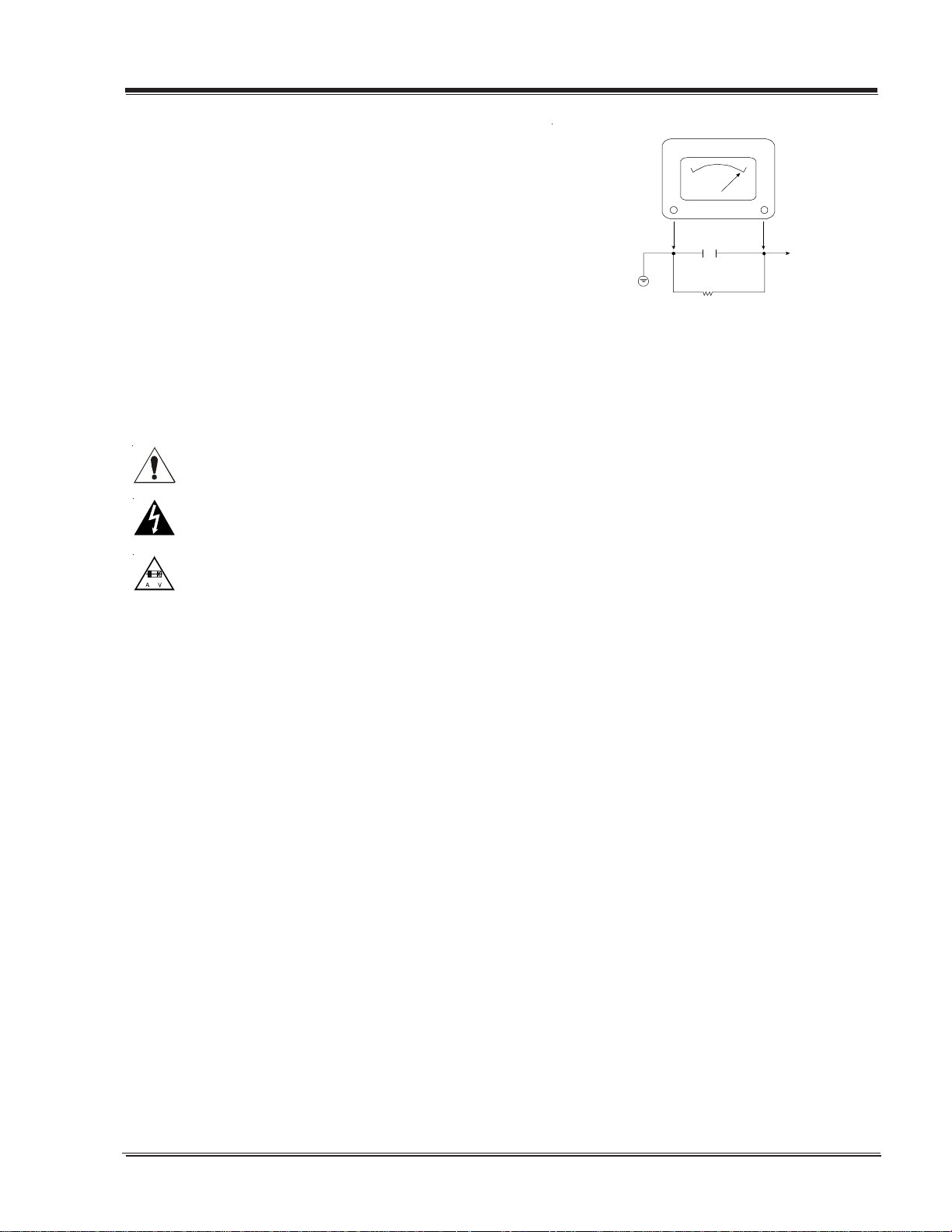
6. After re-assembly of the set, always perform an AC leakage test on all exposed
metallic parts of the cabinet (the channel selector knobs, antenna terminals,
handle and screws) to be sure that set is safe to operate without danger of
electrical shock. DO NOT USE A LINE ISOLATION TRANSFORMER DURING THIS
TEST. Use an AC voltmeter having 5000 ohms per volt or more sensitivity in
the following manner: Connect a 1500 ohm, 10 watt resistor, paralleled by
.15 mfd 150V AC type capacitor between a known good earth ground (water
pipe, conduit, etc.) and the exposed metallic parts, one at a time. Measure
the AC voltage across the combination of 1500 ohm resistor and .15mfd
capacitor. Reverse the AC plug by using a non-polarized adaptor and repeat
AC voltage measurements for each exposed metallic part. Voltage measured
must not exceed 0.75 volts RMS. This corresponds to 0.5 milliamp AC. Any
value exceeding this limit constitutes a potential shock hazard and must be
corrected immediately.
Good Earth Ground
such as the Water
Pipe, Conduit, etc.
X-RADIATION
1. Be sure procedures and instructions to all service personnel cover the
subject of x-radiation. The only potential source of x-rays in current TV
receivers is the picture tube. However, this tube does not emit x-rays when
the HV is at the factory-specified level. The proper value is given in the
applicable schematic. Operation at higher voltages may cause a failure of the
picture tube or high-voltage supply and, under certain circumstances may
produce radiation in excess of desirable levels.
2. Only factory-specified CRT anode connectors must be used.
3. It is essential that the service personnel have available an accurate and
reliable high-voltage meter.
4. When the high-voltage circuitry is operating properly, there is no possibility
of an x-radiation problem. Every time a color chassis is serviced, the
brightness should be run up and down while monitoring the high voltage
with a meter, to be certain that the high voltage does not exceed the
specified value and that it is regulating correctly.
5. When troubleshooting and making test measurements in a product with a
problem of excessively high voltage, avoid being unnecessarily close to the
picture tube and the high voltage power supply. Do not operate the product
longer than necessary to locate the cause of excessive voltage.
6. Refer to HV, B+, and shutdown adjustment procedures described in the
appropriate schematics and diagrams (where used).
IMPLOSION
1. All direct view picture tubes are equipped with an integral implosion
protection system; take care to avoid damage during installation.
2. Use only the recommended factory replacement tubes.
TIPS ON PROPER INSTALLATION
1. Never install any receiver in a closed-in recess, cubbyhole, or closely fitting
shelf space over, or close to, a heat duct, or in the path of heated air flow.
2. Avoid conditions of high humidity such as: outdoor patio installations
where dew is a factor, near steam radiators where steam leakage is a factor,
etc.
3. Avoid placement where draperies may obstruct venting. The customer should
also avoid the use of decorative scarves or other coverings that might
obstruct ventilation.
4. Wall- and shelf-mounted installations using a commercial mounting kit must
follow the factory-approved mounting instructions. A product mounted to
a shelf or platform must retain its original feet (or the equivalent thickness
in spacers) to provide adequate air flow across the bottom. Bolts or screws
used for fasteners must not touch any parts or wiring. Perform leakage tests
on customized installations.
5. Caution customers against mounting a product on a sloping shelf or in a
tilted position, unless the receiver is properly secured.
6. A product on a roll-about cart should be stable in its mounting to the cart.
Caution the customer on the hazards of trying to roll a cart with small
casters across thresholds or deep pile carpets.
7. Caution customers against using a cart or stand that has not been listed by
Underwriters Laboratories, Inc. for use with its specific model of television
receiver or generically approved for use with TVs of the same or larger screen
size.
8. Caution customers against using extension cords. Explain that a forest of
extensions, sprouting from a single outlet, can lead to disastrous
consequences to home and family.
.C. Voltmet er
0.16uF
1600 OHM
10 WATT
Place this probe
on each exposed
metal part.
3828VD0205B CH-FLAT - SAFETY
i
PRODUCT SAFETY SERVICING GUIDELINES FOR AUDIO-VIDEO PRODUCTS
g
E
X-Radiation
To prevent possible exposure to x-radiation caused by excessive CRT
anode voltage, the CH-Flat chassis incorporate a “High Voltage
Shutdown” circuit. This circuit senses the level of a flyback pulse
from the “Flyback Transformer” representative of the actual high
voltage on the CRT anode. When this level exceeds a predetermined
voltage, the circuit shuts down the TV set, preventing further generation of anode voltage.
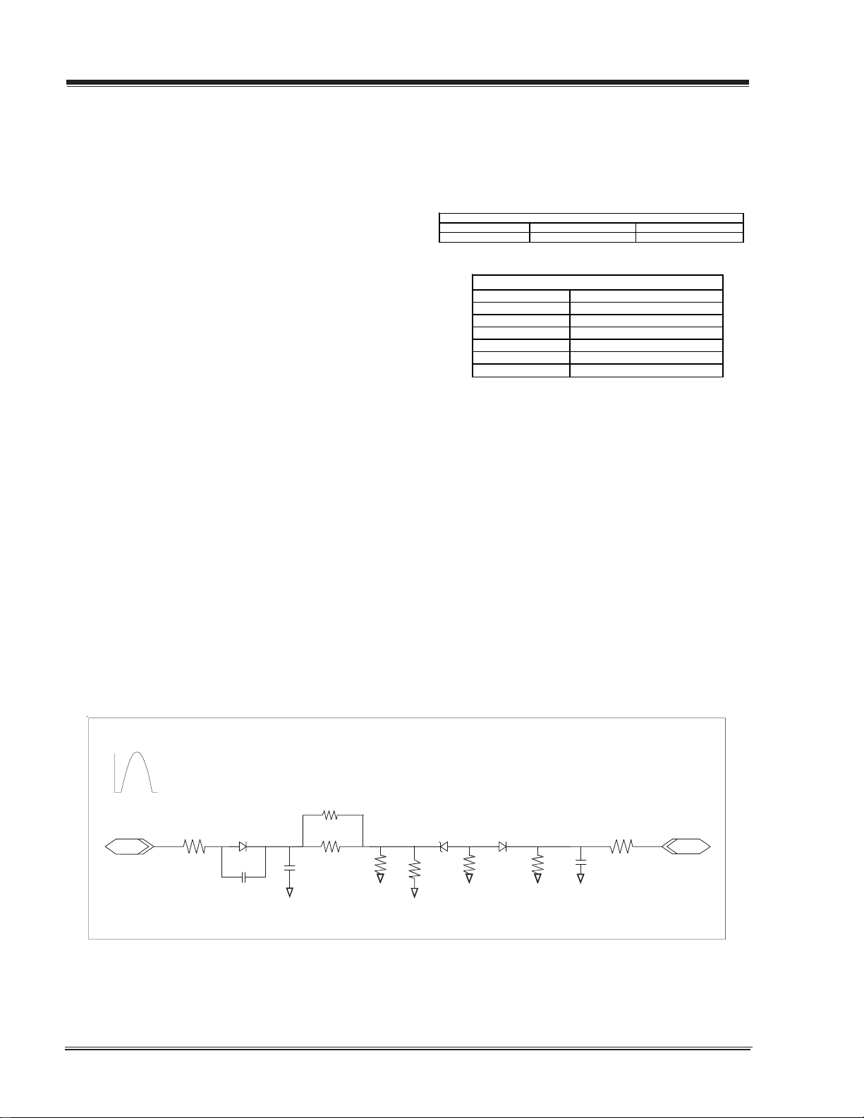
Shutdown Circuit Operation
(Refer to Figure below)
The flyback pulse voltage from pin 6 of TX3201 (Flyback Transformer) is peak detected (rectified) by the action of diode DX3001
and capacitor C3003. This form a DC voltage appearing on C3003
representative of the CRT anode voltage (HV) produced by TX3201.
This voltage is divided down by precision resistors RX3004, RX3005,
RX3006 and RX3007. This lower voltage appears on the zener diode
ZD3000; when this voltage exceeds by 3.5 Vdc the “zener voltage”
the HV shutdown occurs (pin 29 of ICX2200).
CRT Anode High Voltage Measurement Procedure
Each CRT screen size has it’s own safe operating anode and shutdown voltage. Critical safety component (designated with an ‘X’ in
the component designator) are designed to operate the CRT at a
safe operating anode voltage and provide proper shutdown thresholds. If replacement of any of these components are deemed necessary, it is important to use original type Zenith components. After
replacement is made, confirm proper anode voltage using the following procedure.
Observe the anode voltage meter reading and compare with the
table below for the proper CRT screen size. If the voltage reading
is higher than the maximum, verify circuit component values and
proper operation.
CRT Screen Size Nominal Anode Voltage (KV) Max. Shutdown Voltage (KV)
20" 26+/-1.0 32
COMPONENTS WITH ANY INFLUENCE IN HV INCREAS
Fly-Back Transformer CX3215
Deflecti on Yoke CX3216
CX3203 RX3753
CX3204 RX3754
CX3205 RX3755
CX3206 RX3756
CX3207
CRT Anode Vol ta
e
HV SHUTDOWN PROCEDURE.
·After discharging the CRT, connect a high impedance-high voltage meter to the CRT anode
·Access Video Menu and adjust Brightness and Contrast controls
for minimum screen luminance (beam current to 0 mA).
Measurement of the CRT anode voltage must be performed using a
high impedance-high voltage meter, with no raster on the screen,
and operating at nominal horizontal frequency, 15.75 Khz (NTSC
signal).
After discharging the CRT, connect a high impedance-high voltage
meter to the CRT anode. Turn the television ‘on’ and confirm a good
signal is being displayed. Reduce Brightness and Contrast settings
until the picture is well extinguished.
Flyback P ulse
RX3007
IN
RX3209
From Pin 6
Of TX3201
DX3001
C3003
RX3006
RX3005
C3002
·Wait until the Video Menu or display disappear.
·Connect a variable Resistor (1 MW) between ground and junction of RX3754 and RX3755, and decrease slowly the resistance
value until shutdown occurs.
·Measure High Voltage shutdown.
SHUTDOWN
TO PIN 29
ICX2200
RX3004
ZD3000
R3003
D3002
RM3002
RM3001
C3001
OUT
3828VD0205B CH-FLAT - SAFETY
ii

TABLE OF CONTENTS
SECTION 1.................GENERAL INFO
INTRODUCTION ...................................................... 1-1
Overview ........................................................ 1-1
INTERFACES .......................................................... 1-2
SUPERPORT - MPI ............................................ 1-2
MULTIPLE PROTOCOL INTERFACE ......................... 1-2
EBC (EDGE BOARD CARD) ................................... 1-2
CONNECTION CENTER ON BACK/REAR OF TV........... 1-2
REMOTE - HP602 ................................................... 1-5
INSTALLER’S PROGRAMMER LT-2000/02 .................. 1-6
QUICKSET II PROGRAMMER ................................ 1-6
LEARN FROM TV ............................................... 1-6
TEACH TO TV ................................................... 1-6
SET CLONE CLOCK FROM TV ................................ 1-7
DISPLAY TV SETUP ............................................ 1-7
DISPLAY CLONE SETUP ...................................... 1-7
OPERATION NOTES ............................................ 1-7
USER MENUS .........................................................1-8
SETUP MENU ................................................... 1-8
AUTOPROGRAM................................................. 1-8
CHANNEL LABELS ............................................. 1-8
VIDEO MENU ................................................... 1-9
ON SCREEN DISPLAYS ...................................... 1-10
RADIO FEATURE ............................................. 1-11
FM ADD/DEL ................................................. 1-11
FM LABELS .................................................... 1-11
TIMER SETUP ................................................. 1-11
RADIO SCREEN SAVER ..................................... 1-11
CHANNEL BANK ............................................. 1-12
SECTION 5......................DIAGRAMS
H20H52DT/DT8 Exploded View .......................... 5-1
SECTION 6.....................SCHEMATICS
Main Processor ................................................ 6-1
Video Processor Circuit ..................................... 6-2
Audio Amplifier ............................................... 6-3
Power Supply .................................................. 6-4
Deflection Circuit ............................................ 6-5
AM_FM Radio .................................................. 6-6
Pillow Speaker ................................................ 6-7
Edge Cardt ..................................................... 6-8
MPI Card Circuit .............................................. 6-9
Video Output ................................................ 6-10
PCB Layout 1 Top .......................................... 6-11
PCB Layout 1 Bottom ..................................... 6-12
PCB Layout 2 Top .......................................... 6-13
PCB Layout 2 Bottom ..................................... 6-14
SECTION 2......................FACTORY &
INSTALLERS MENU
ACCESING FACTORY MENU .......................................2-1
FACTORY MENU OPTIONS ................................... 2-1
ACCESING INSTALLERS MENU ..................................2-3
INSTALLERS MENU ADJUSTMENTS ........................ 2-3
ADJUSTMENT CHART (INSTALLER MENU SETTINGS) . 2-8
SECTION 3.......................SERVICING
SERVICING ............................................................ 3-1
GENERAL INFORMATION ..................................... 3-1
MODULE-LEVEL SERVICING ................................. 3-1
SERVICING THE POWER SUPPLY ........................... 3-1
IF SERVICING....................................................3-3
AGC DELAY .......................................................3-3
G2 ADJUSTMENT ...............................................3-4
FOCUS ADJUSTMENT ......................................... 3-4
PURITY & CONVERGENCE SETUP PROCEDURE ........ 3-5
HORIZONTAL-TILT WEDGE ADJUSTMENT ................ 3-6
UNUSUAL TILT CASE ......................................... 3-6
SECTION 4..................MODEL PARTS
H20H52DT/DT8 .................................................... 4-1
TOC - 1 CH-FLAT -TOC
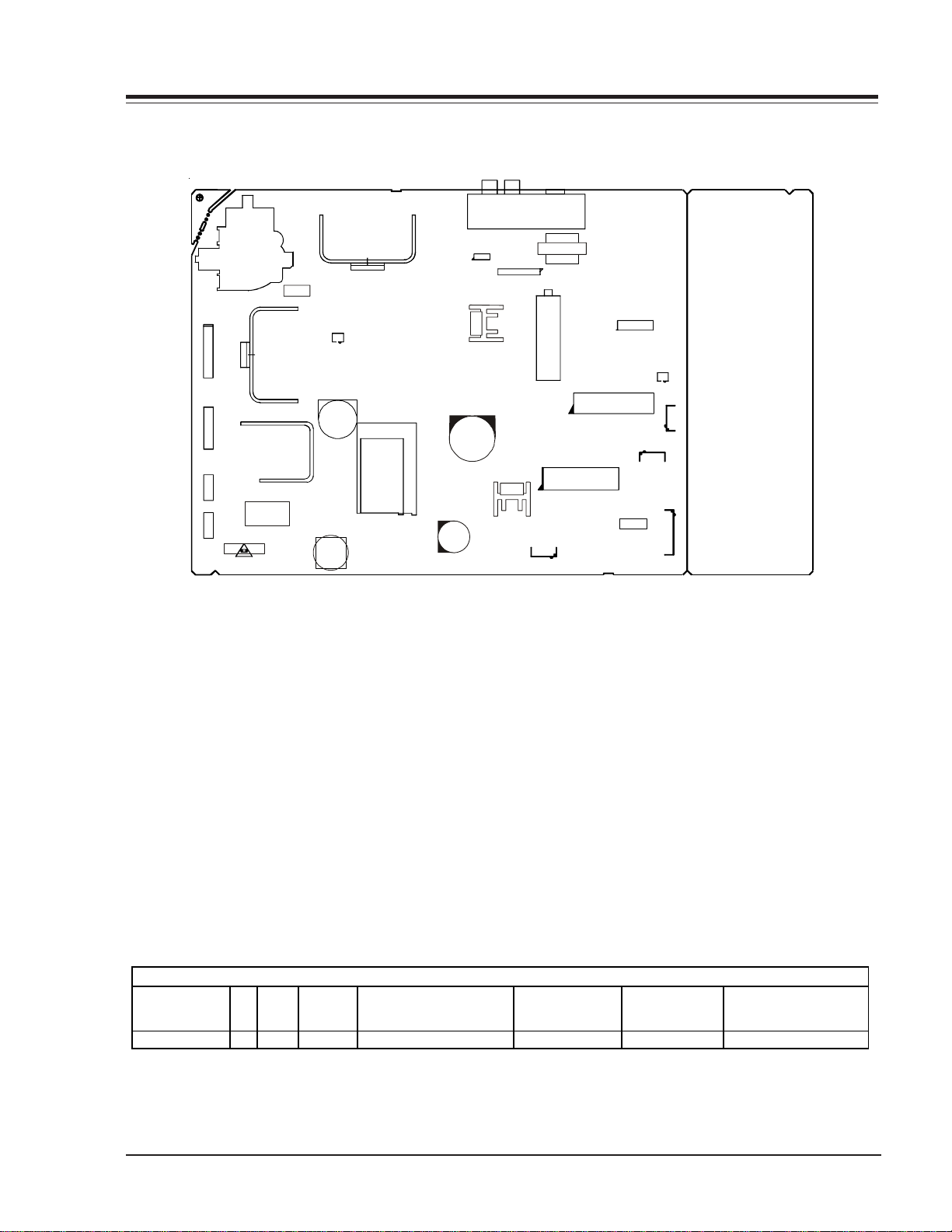
OVERVIEW
JP1
CX4003
CX3610
IC801
ICX3850
IC2800
ICX3801
TU1240
CN2K6
IC6000
Tx900
IC4201
CON4H2
ICX2200
4G9
CN2C5B
IC6001
CN10VGA 1
CN3Y3
CN3T8
CN3R8
TX3201
FX3400
Qx3200
LX3400
CN2C5A
ICX3670
ICX2100
2H4
CX3653
TX3612
TX4001
INTRODUCTION
This manual provides a brief explanation in an overall view of the CH-Flat chassis used on Health view model flat screen.
The CH-Flat serie chassis features seven ICs for all signal, sync, and sweep processing.
ICX2200 - Handles all of the audio/video, sync and sweep drive processing.
IC6000 - Main microprocessor. It is tied directly to the keyboard and the infrared detector.
IC6001 - System memory .
ICX2100 - Handles vertical sweep.
IC2800 - Audio switch.
ICX3612 - Power supply. This is a switching type supply powered by a bridge rectifier circuit. This IC supplies power f or
Microprocessor and powering the LSP or MPI port third party application.
The table below contains some general information about the Commercial model. Refer to the interconnect and parts list
for more information.
CH-Flat C hassis Model Information
REMOTE
MODEL SCR JACKS AUDIO EXTRA FEATURES
H20H52DT/DT8
20 3 MONO SuperPort Sl ot , MPI Car d 6712SC A227A 0IMCRK E018A 3828VA0518B
3828VD0205B 1-1 CH-FLAT - OVERVIEW
CONTROLLER
MICRO OP GUIDE/OWNER MANUAL
OVERVIEW (continued)
A
INTERFACES
SUPERPORT - MPI
Zenith Commercial Product receivers are now being
adapted to interact with other equipment. Prime examples of this can be found in Lodging and Health Care
situations where the set is controlled from the main office.
All this is made possible by the new technology that is
being built into these receivers. The SuperPort and/or
Multiple Protocol Interface (MPI) jack and associated
circuitry allow remote control of the set.
MULTIPLE PROTOCOL INTERFACE
Television functions and features are controlled by the
communication of commands and status information
through a Superport by the MPI interface.
EBC (EDGE BOARD CONNECTOR)
Allows easy access for removing/installing accessory
modules providing a rail mounted slide-through card.
These cards might contain one of the above features.
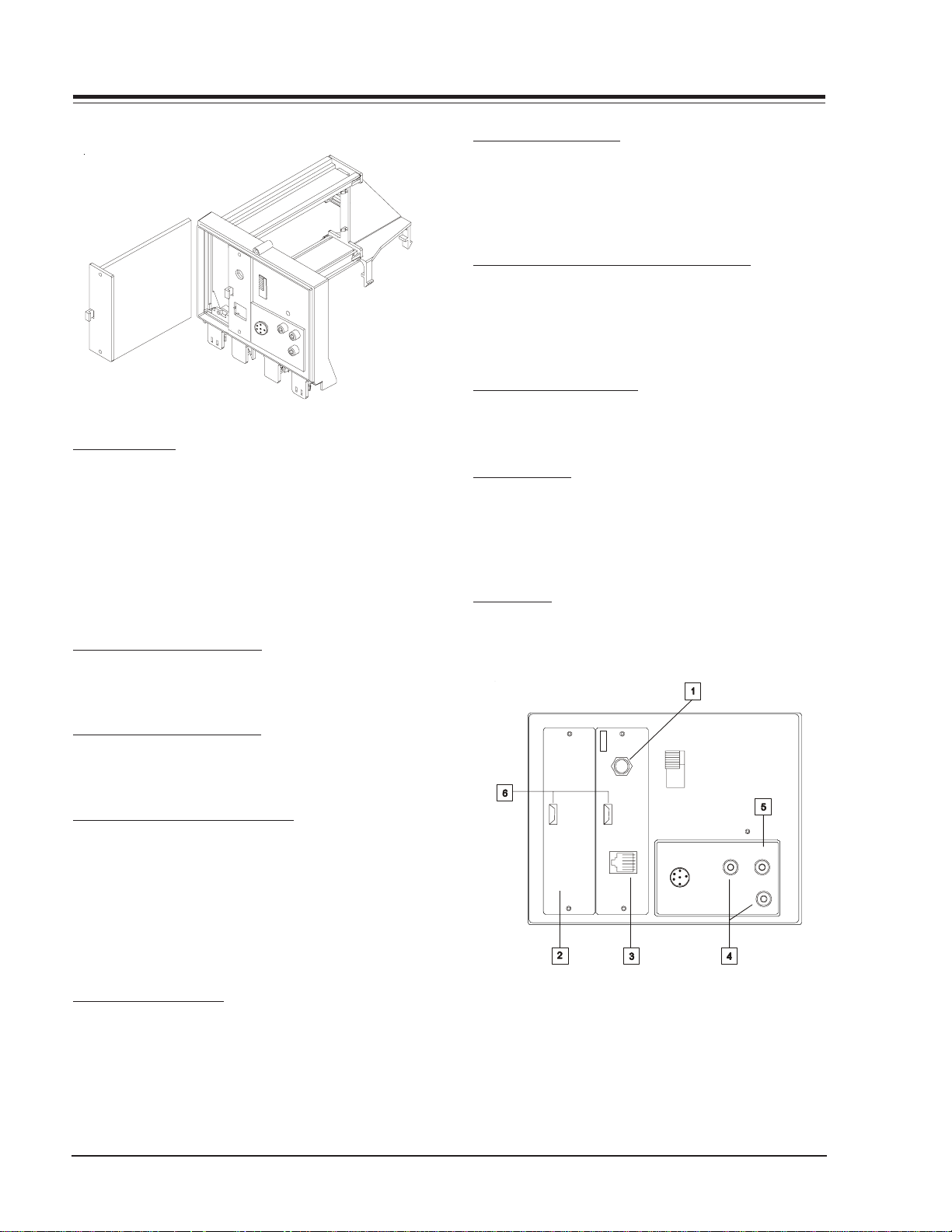
CONNECTION CENTER ON BACK OF TV
The connection on the back of the TV contains the input and output interfaces.
CONNECTION CENTER ON REAR OF TV
The connection center on the rear of the TV allows for
connection of the viewing source. The diagrams list the
use of each jack on the connection center.
2. SUPERPORT LOCATION
Provides for easy installation of local service provider
accesory module without removing the cabinet and receives operating power and all necessary interface signals through internal connections.
3. MPI (MULTIPLE PROTOCOL INTERFACE) JACK
Standard RJ11 jack to provide interface with in-room
entertainment and video services. Also used with installer’s
programmer (page 1-5) for programming other TVs in
the system with the sam e features as the master TV.
4. VIDEO IN AND AUDIO IN
Use the Video and Audio In jacks for baseband video
and audio input signals from a VCR or other signal source.
5. SPEAKER OUT
Use this jack for connection of an 8-ohm extension
speaker to get television sound at a remote location.
The speaker in the TV remains active, while a monaural
audio output is heard from the remote speaker.
6. EBC KNOB
For handling/removal of EBC (Edge Board Card).
NTENNA
CABLE
MPI
TV
SPKR
PILLOW SPEAKER
VIDEO IN
SPEAK ER OUT
AUDIO IN
1. ANTENNA/CABLE JACK
Use the jack for 75-ohm antenna-type signal connections to the TV. Attach antenna, cable TV line, or other
video equipment to jack. The input cable may come from
an outdoor or master antenna, cable TV line, cable decoder box, or the RF output from a VCR.
3828VD0205B 1-2 CH-FLAT - OVERVIEW
OVERVIEW (continued)
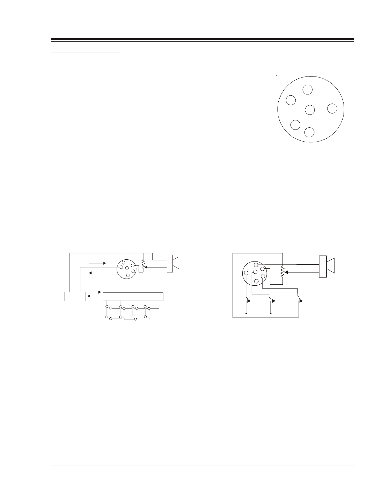
PILLOW SPEAKER INTERFACE
DESCRIPTION
The pillow speaker interface within the TV, provides three remote control
lines and an audio output. It is intended for connection to a patientpendant remote control, or entertainment audio and nurse call system. All
lines are isolated from the AC power line and ground. Isolation of the
control lines is provided by optoisolators. These are no relays or inductive
components in the control lines. Isolation of the audio output is provided by an isolator transformer.
Purpose of Interface Pins
Pin #1 External TV ON /OFF closure.
Pin #2 Open (not used).
Pin #3 External Channel Up Closure or Data In.
Pin #4 Common for External Control.
Pin #5 Audio Output. The impedance from this pin to earth ground is a
nominal 10 Megohm static leakage resistor in parallel with an 1100
picofarad capacitor.
Pin #6 External Channel Down Closure.
4
5
6
1
2
3
1 TV ON /OFF
2 Open
3 Chan Up/Data In
4 Common
5 Audio Out
6 Chan Down
THEORY OF MULTIPLEXED DA T A MODE
Common
Power/ Data
Separator
Data
Power
Power
Data
Common
4
5
3
6
1
2
Serial Data Encoder
H
H
H
H
H
H
Speaker
Volume
control
H
H
Pins 3 and 4 support a built-in interface which allows
multiple functions on a single wire by means of serial
digital coding. Pin 3 will source up to 2 mA during the
digital "0" interval to supply operating power for the
digital encoder located in the pillow speaker. The coder
must sink a minimum of 5 mA to pin 4 during the digital
"1" interval and provide the correct serial data stream.
Pillow speakers meeting this specification are available
from independent manufacturers such as Curbell, Inc.
(Manufacturers wishing to produce compatible pillow
speakers or other products should contact Zenith Commercial Products for detailed specifications). An isolated
audio output is at pins 4 and 5.
THEORY OF SIMPLE SWITCH MODE
4
5
6
3
Chan
Up
1
2
Chan
Down
Volume
TV
On/Off
Speaker
Mode pins 1, 3, and 6 are connected to pin 4 by way of
momentary-action switches to activate indicated control function. These pins are 13 Vdc positive with respect to pin 14 when the switches are open. Loop current is 8 mA with the switches closed. Isolated audio
output is at pins 4 and 5. Mode of operation is identical to previous Zenith models using the 5-Wire Interface
with the exception of higher open circuit voltage (was
7 Vcd ) and higher loop current (was 2.5 mA).
3828VD0205B 1-3 CH-FLAT - OVERVIEW

OVERVIEW (continued)
SETTINGS MIN/MAX VOLUME LEVELS
Use the following procedure to adjust minimum volume
and maximum volume for pillow speaker. This procedure
not only sets the maximum volume level that the pillow
speaker can produce, but also prevents the TVs volume
from accidentally being adjusted to level which is too
low or too loud.
1. Connect pillow speaker . Place INT/EXT speaker switch
on back of TV in EXT position.
2. Set VOLUME control on pillow speaker to maximum
volume position.
3. Access Service Menu by following the instructions
given in the “Service Menu” section of this book. Select
the MAX volume. Use the ADJUST key to set highest
desired volume level within the range of 0 to 63. This
will be the highest desired volume level, as heard at the
pillow speaker .
4. Select the MIN volume. Use the ADJUST key to set
the lowest desired volume level within the range of 0 to
63. This will be the lowest desired volume level as heard
at the pillow speaker.
5. Make no further adjustments and exit the Service
Menu.
The TV is now adjusted for minimum and maximum volume settings. All further adjustments of the TVs volume
should be made by using the VOLUME control on the
pillow speaker .
3828VD0205B 1-4 CH-FLAT - OVERVIEW
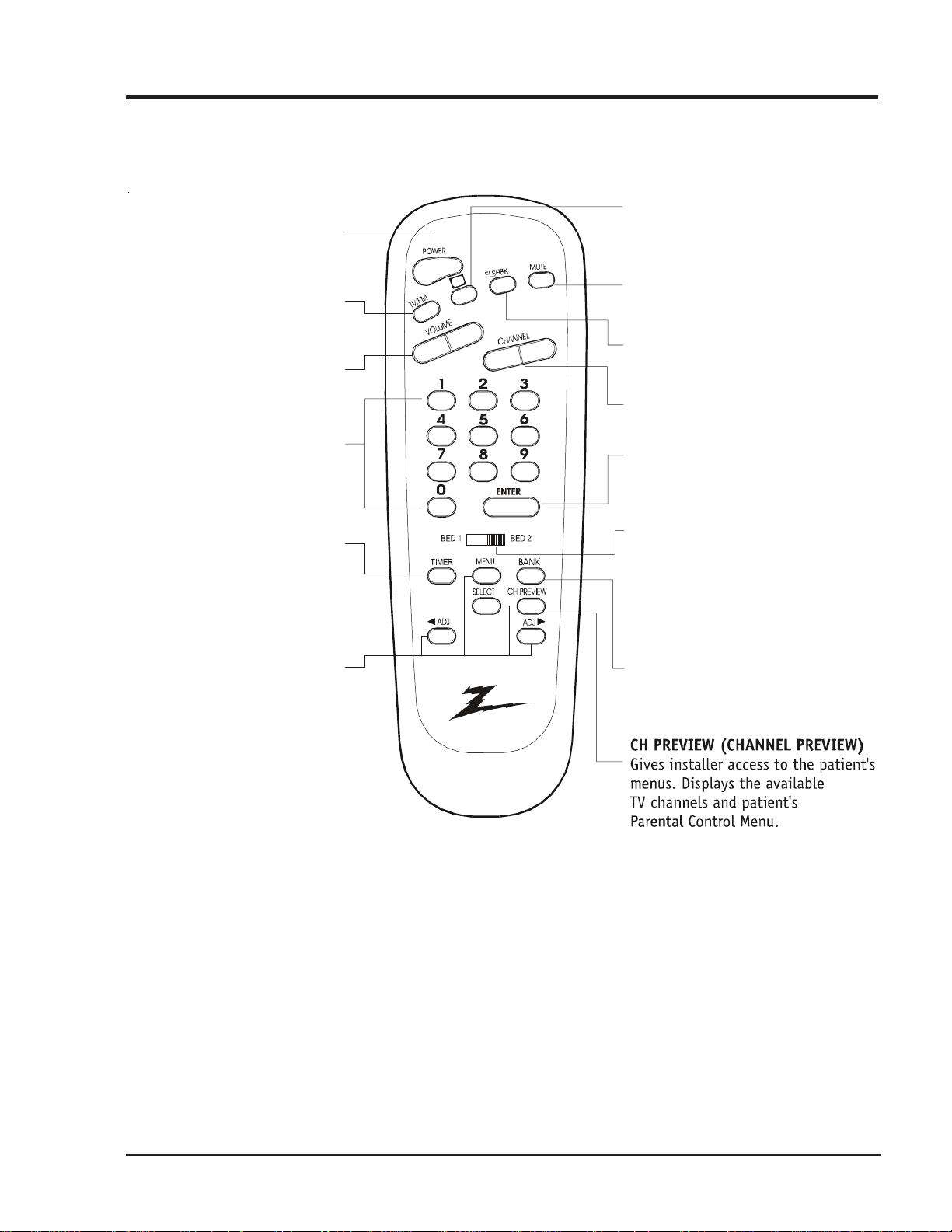
POWER
)
Turns TV ON or OFF.
TV/FM
Selects TV or Radio on
TVs equipped with FM radio.
VOLUME LEFT/RIGHT
Adjusts the soun d le vels.
NUMBERED KEYPAD
Selects channels directl y and
enters numeric values
for some options.
TIMER
Press repeatedly to adjust TV
turn-off tim e up to 4-h our s.
Use to pick AM/PM
in clock menu.
MENU/
SELECT/ADJ (ADJUST)
Press MENU r epeated l y during
on-screen menu
operati on s to adjust a n option.
(Righ t)
Press durin g on- sc reen menu
operati on s to adjust a n option.
OVERVIEW (continued)
C
C
CC (CLOSED CAPTIONING
Press to access closed captions.
Press ENTER to exit.
MUTE
Turns sound Off and On, while
the picture remains.
FLSHBK (FLASHBACK)
Return to the last cha nnel viewed.
CHANNEL UP/DOWN
Tunes to next available channel
ENTER
Press to view Channel /Time
d or to remove any
isplay
on-screen display or
menu.
BED 1/ BED 2 (*See Note Below)
Determines the cod e set transmitted,
Bed 1 or Bed 2. Switch setting must
correspond to item 27,
HOSPITAL MODE setting in the
TV's Intaller Menu.
BANK
Press and r epeat to sel ect to
select a Channel Memory
Bank - - 1,2,3 or 4 (standby).
HP602
124-00213-06
*Note: Bed 1 - Bed 2 switch on installer/patient remote. The position of the Bed 1-Bed 2 switch must correspond to the
setting in the Installer's menu. The switch above can be set by sliding it to the Bed 1 or Bed 2 position. On the patient's
remote, the Bed 1 or Bed 2 position can be selected by using a paper clip or a ball-point pen to slide the switch to the
correct position.
Left position = Bed 1.
Right position = Bed 2.
3828VD0205B 1-5 CH-FLAT - OVERVIEW
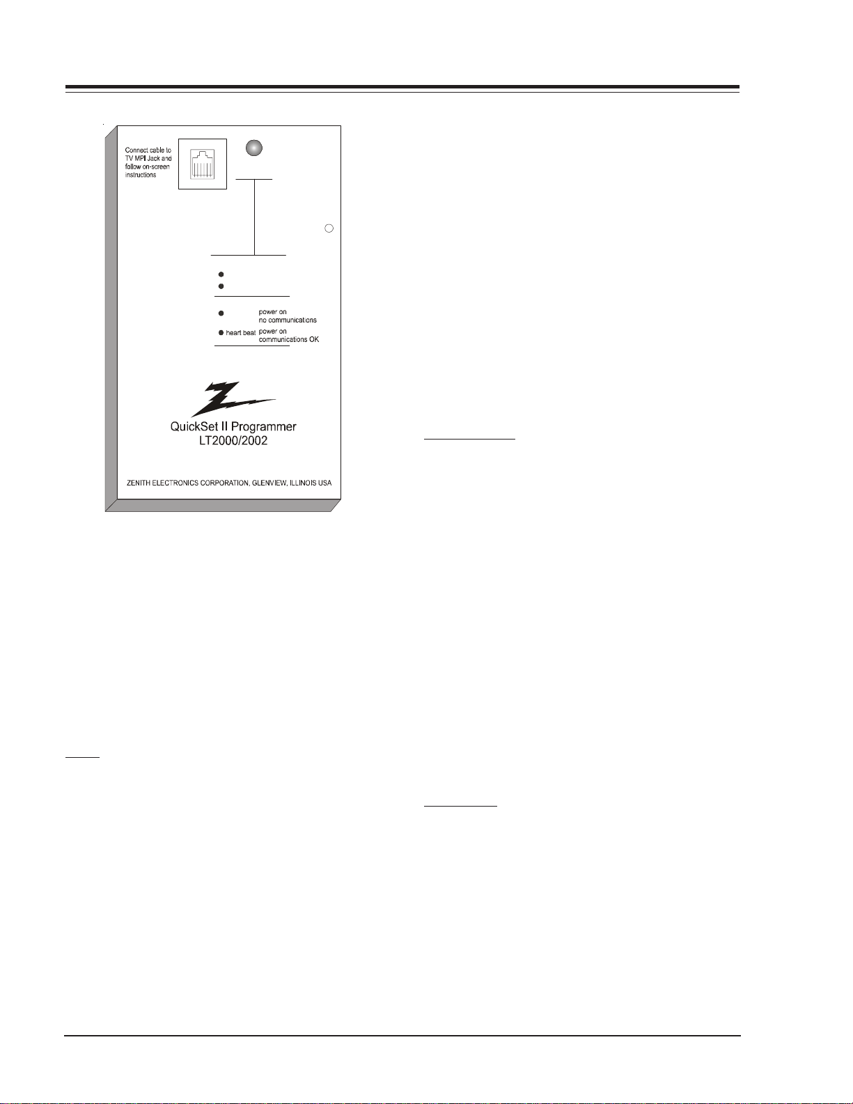
OVERVIEW (continued)
Status
Indicator
MPI
Reset
Color
battery OK
green
battery low
red
Blin k pattern
slow
LT-2000/2002 CLONE PROGRAMMER
The Quick Set II programmer LT2000 or LT2002 allows
custom setup and programming information to be quickly
copied from a master TV into multiple television sets.
Once learned from the master, setup data is retained in
the LT2002 for future use and recall.
When using the LT2002, operation will be easier if the
TV is connected to a good quality signal and displaying
a stable picture. To operate the LT2002, use the indicated keys on an installer’s remote or user’s remote, or
the front panel keys on the TV receiver.
SETUP
Begin the programming process by setting up a master
TV set using one of the installer’s remotes or an MBR
remote. Follow the instructions in the operating guide
for the specific TV model. Remember to set all features
that will be customized including the channel scan list,
channel labels, and installer menu setups.
Next connect the LT2002 to the master TV set using the
cable provided with the programmer. Connect the cable
between the MPI jack on the TV and the programmer.
The TV set automatically activates the programmer.
Once connected, check the “Status Indicator” LED on
the progr ammer. If the indicator is gr een an d flashing (a
double-blink “heartbeat” pattern), proceed to the next
step.
NOTE: A slowly flashing green light indicates there
is a problem with the communications between
TV and programmer. In this case, check for
damaged cable, poor contacts, or other
connection problems. If the status indicator
is red, the programmer batteries are low.
If communications are good, the sign-on screen will be
displayed on the TV screen as shown on the quick setup
instructions. If the intention is to set the TV’s or
programmer’s real-time clocks, and not the clone clock
or TV clock time settings, then press a key to proceed to
the main clone menu.
If a previously stored TV setup is in a particular clone
memory, it may be changed if desired by overwriting it
with a new setup. There is no need for a separated memory
clear operation. Setups stored in programmer memory
are nonvolatile and will be retained even after a battery
change.
LEARN FROM TV
Select “Learn From TV” then press ON/OFF, POWER, or
ENTER to begin learning process. Alternatively, use the
TV front panel CHANNEL UP or CHANNEL DOWN keys to
highlight choice. Press ON/OFF, POWER, or ENTER to activate. The next screen will allow a choice of four available memories to store this TV setup. Four different TV
setups can be stored in the LT2002.
Using the On-screen menu, choose a memory or choose
to return to the main selecti on menu. N ow press ON/OFF ,
POWER, or ENTER to activate your selection. The next
screen allows one last opportunity to check the versions
of TV and clone setups.
Press ON/OFF or POWER to activate the learning cycle, or
press any other keys to return to the selection menu to
make another choices.
Once a process has begun, the TV screen will display
“LEARNING IN PROGRESS”. Please wait for the pr ocess to
complete. When the TV screen displays “LEARNING COMPLETED”, press any key to end the learning process and
return to the clone selection menu.
TEACH TO TV
Select “TEACH TO TV”, an d then press ON/OFF, POWER, or
ENTER to begin teaching process. Alternatively, use the
TV front panel CHANNEL UP or DOWN keys to highlight
the choice and then press ON/OFF, POWER, or ENTER to
activate. The next screen displays a choice of the four
available memories that can be copied to the TV. Select
the desired memory number, and press ON/OFF, POWER,
or ENTER to begin the teaching process. Alternatively,
use the TV front panel CHANNEL UP or DOWN keys to
highlight choice. Press ON/OFF, POWER, or ENTER to begin.
3828VD0205B 1-6 CH-FLAT - OVERVIEW

OVERVIEW (continued)
Using the on-screen menu, select a memory or return to
the main selection menu. Then press ON/OFF, POWER, or
ENTER to activate the selection.
The next screen allows for one last opportunity to check
the versions of TV and clone setups. Press ON/OFF or
POWER to activate the teaching cycle, or any other key
to return to the selection menu to make other choices.
Once a process has begun, the TV screen will display the
“TEACHING IN PROGRESS” message. Please wait for the
process to complete. When the TV screen displays “TEACHING COMPLETED”, press any key to end the teaching process and return to the clone selection menu.
SET CLONE CLOCK FROM TV
To set the real-time clock in the LT2002, select “SET
CLONE FROM TV” and then press ON/OFF, POWER, or ENTER to copy current TV time to the clone clock. Alternatively, use the TV front panel CHANNEL UP or CHANNEL
DOWN keys to highlight the choice. Then press ON/OFF,
POWER, or ENTER to activate.
This process will return the L T2002 to th e sign-on scr een
to display the clone and TV clock settings. Press a key
to go to the clone selection menu and perform other
functions, or simply disconnect if the time setting was
the last task.
SET TV CLOCK FROM CLONE
To set the real time clock in the, select “SET TV CLOCK
FROM CLONE” and then press ON/OFF, POWER, or ENTER
to copy current LT2002 time to the TV clock. Alternatively, use the TV front panel CHANNEL UP or CHANNEL
DOWN keys to highlight the choice. Then press ON/OFF,
POWER, or ENTER to activate.
This process will return the L T2002 to th e sign-on scr een
to display the clone and TV clock settings. Press a key
to go to the clone selection menu and perform other
functions, or simply disconnect if the time setting was
the last task.
DISPLAY TV SETUP
Select “DISPLA Y TV SETUP”, and then press ON/OFF , POWER,
or ENTER to begin the teaching process. Alternatively,
use the TV front panel CHANNEL UP or CHANNEL DOWN
keys to highligh t your choice . Then press ON/OFF , POWER,
or ENTER.
The TV screen will display the items in the service menu
setups. Use this function to quickly check the TV for
correct setup. Press any key to clear display and return
to the clone selection menu.
DISPLAY CLONE SETUP
Select “DISPLAY CLONE SETUP” and then press ON/OFF,
POWER, or ENTER to begin the teaching process. Alternatively , use the TV fr ont pan el CHANNEL UP or CHANNEL
DOWN keys to highlight the choice, then press ON/OFF,
POWER, or ENTER to begin.
The TV screen will display the memory selection menu.
Select the desired memory number, and then press ON/
OFF, POWER, or ENTER to display the contents of the
selected memory . Altern atively , use the TV’s CHANNEL UP
or CHANNEL DOWN keys to highlight the choice, then
press ON/OFF, POWER, or ENTER to begin.
The TV screen will display items in the factory menu setup.
Use this function to quickly check contents of a particular clone memory for correct setup. Press any key to
clear the display and return to the clone selection menu.
OPERATION NO TES
Disconnect the LT2002 from the TV set when the desir ed
task has been completed. Disconnecting the clone automatically switches it off. The real time clock continues to run when the main circuits are switched off.
After replacing exhausted batteries, or if the programmer behaves strangely after a static shock, use a paper
clip or similar instrument inserted through the small hole
marked “RESET” to activate the internal reset switch and
restore normal operation. After reset, check the real-time
clock setting. It may be necessary to reset the clock
from a TV programmed to the correct time.
The specific microprocessor used in any TV set may be
determined by activating the service menu. The microprocessor part number appears at the top of the screen
with the service menu is activated. Processors before
the 221-01006 has limited screen display capability . They
cannot display entire screens as shown in the quick setup
instructions accompanying the LT2002 programmer. Use
the printed menu illustrations on the quick setup sheet
as an aid in making programming choices.
3828VD0205B 1-7 CH-FLAT - OVERVIEW
USER MENUS
INSTALLA TION SETUP
INSTALLER’S REMO TE AND CLONE PROGRAMMER
To perform the installation setup for several TVs, you
need an installer’s remote, such as the HP602Z, and the
LT2000/02 Clone Programmer (See page 1-10). The
HP602Z Installer’s Remote allows access to the Installer’s
Menu, User Menus, and Source/Channel Banks. The
LT2002 Clone Programmer is used to duplicate a TV’s
setup and install it on one or more additional TVs.
Press the POWER key on the Installer remote control to
turn on the TV.
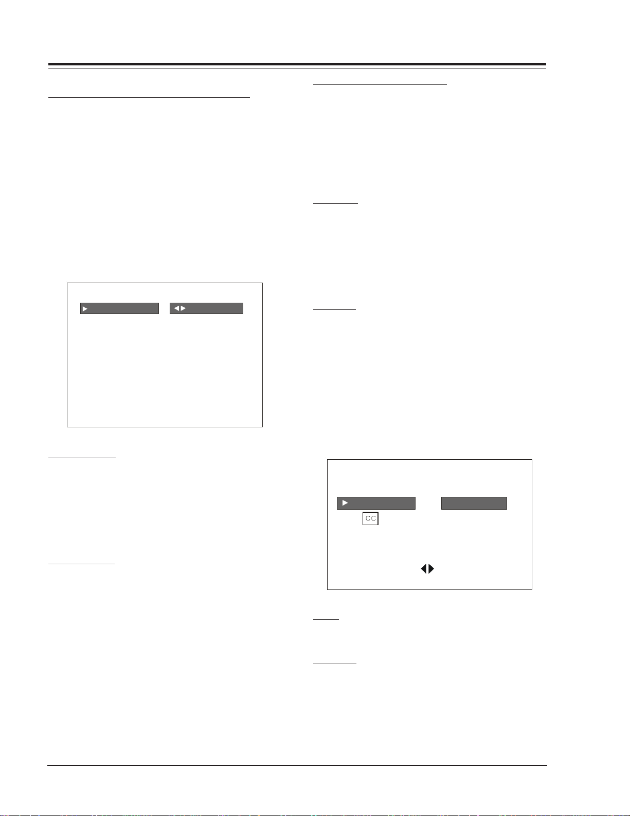
SETUP MENU
Press the MENU key on the Installer’s remote repeatedly
so that the SETUP MENU appears on the screen.
SETUP MENU
AUTO PROGRAM TO PROGRAM
ADD/DEL/BLNK
CH. LAB E LS
LOCK SET
C
TIMER
CAPTIONS
LANGUAGE
AUTO PROGRAM
Using the SELECT on the remote control, highlight AUTO
PROGRAM on the screen. Then press a RIGHT/LEFT Adjust
arrow button to reach the AUTO PROGRAM screen.
Using the Up Arrow, choose either CABLE TV or OFF-AIR
ANTENNA. Press a Right of Left Adjust arrow to begin the
Channel Search and stores them in memory for user access.
ADD/DEL/BLNK
Press the Up Arrow repeatedly to highlight the ADD/
DEL/BLNK option. Use the remote to select a channel.
ADD/DELETE allows tailoring of the channel scan to eliminate unwanted channels and add desired channels that
were not stored during Auto Programming.
Use the number keypad and ENTER to add a deleted channel. Using the RIGHT/LEFT ADJ arrows, pick whether a channel is Added, Deleted, or Blank. Blank is used by hospitals and institutions to send music or informational
messages to an unused channel. When BLNK is selected,
screen will be black while audio continues.
Select any other channels to be changed, and when finished, press ENTER to close the menu.
CH LABELS (CHANNEL LABELS)
Press the MENU key on the remote so that the SETUP
MENU reappears. Use SELECT to choose the CH LABELS
option. Pressing either the RIGHT/LEFT ADJ arrow repeatedly, pick the label you want from the list of available
selections shown in the chart. Select other channels,
and when you are finished, press ENTER to remove the
menu. You also have the option of creating 20 pr ogram-
mable labels having five digits each.
CLOCK SET
Use MENU repeatedly to show the Setup Menu. Use the
Up Arrow to highlight Clock Set. Set the current time;
use the Number keypad to enter the hours, then minutes. For example, enter 06, then 30, to set 6:30 on the
clock. Use the TIMER key to specify AM or PM. Press
ENTER to start the clock and return to TV viewing.
CAPTIONS
CAPTION is a feature that allows the TV to receive closed
captions and/or text options when made available by
the broadcaster.
There are two operating modes for captions: quick/mute
and standard; if quick mute is selected, pressing the cc
key shows the current cc selection.
Use the Right/Left arrows to choose any of the following options: CAPTION 1, CAPTION 2, CAPTION 3, CAPTION
4, TEXT1, TEXT 2, TEXT 3, TEXT 4. Press ENTER to close
the menu.
CAPTIONS SETUP
STANDARDOPER. M ODE
SEL. TYPE
CAPTION LOCK
PRESS SELECT TO CHOOSE
PRESS ADJ
TO CHOOSE
TIMER
TIMER is a feature that allows TV turn on/off automatically each day at the preset time.
LANGUAGE
In the LANGUAGE menu, use the Right/Left arrow to
choose one of the following options: English, Spanish
or French.
Press ENTER to return to TV viewing.
3828VD0205B 1-8 CH-FLAT - MENUS
USER MENUS (continued)
VIDEO MENU
Press MENU repeatedly until the Video Menu appears.
Your options are:
• CONTRAST: Adjusts the contrast of the picture (difference between white and black). Has 64 steps (0 to 63).
• BRIGHTNESS: Adjusts the brightness of the picture
(amount of white). Has 64 steps (0 to 63).
• COLOR: Adjusts the intensity o f the color. Has 64 steps
(0 to 63).
• TINT: Adjusts the tint of the color picture (balances
between amounts of red and green in the TV picture).
Has 64 steps (0 to 63).
• SHARPNESS: Raises or lowers the definition of the TV
picture. The lower the level, the softer the images will
appear (adjusts the sharpness of the picture). Has 64
steps (0 to 63).
• PICTURE PREF: Has two settings; PRESET and CUSTOM.
In the Custom mode the brightness, contrast, color and
tint can be set to a users particular liking. The preset
settings brings up the factory setting for these controls. Preset is selected automatically after an AC power
interrupt.
VIDEO MENU
CONTRAST
BRIGHTNESS
COLOR
TINT
SHARPNESS
PICTURE PREF PRESET
Use the Up Arrow on the remote control to highlight the
setting you want to change. Press Right/Left arrow to
adjust or change the option you have selected.
Press ENTER to return to TV viewing, or press the Up
Arrow to change other options in the video menu.
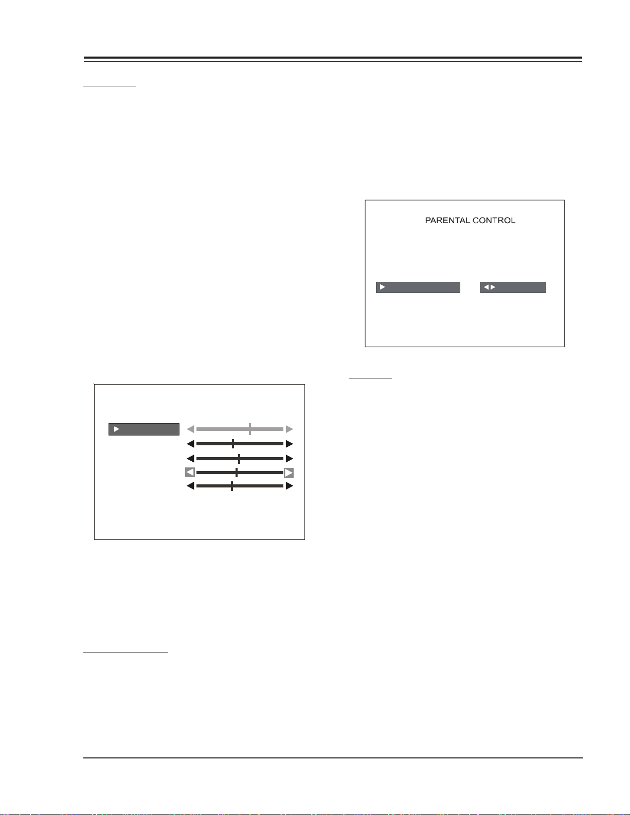
PARENTAL CONTROL
This optional feature can be used to prevent (block)
unwanted programming from appearing on your TV.
PARENTAL CONTROL offers the user a wide variety of options and settings that restrict or block programming
that can appear on the TV. PARENTAL CONTROL allows
users the capability of defining which program ratings
they consider acceptable to younger or more sensitive
viewers.
PARENT AL CONTROL can be pr eset and turned on or off by
a user who specifies the 4 number password. The number
of hours blocked must also be specified.
General audience and children viewer blocks can both
be programm ed into the TV’s memory. Viewer ratings are
specified for both the TV industry and the motion picture industry; both rating systems can be used. The ratings are based mainly on children’s ages.
AUX SOURCES
MPAA RATING
AGE BLOCK
CONTENT BLK
SET HOURS
SET PASSWORD
LOCK ON/OFF
TO BLOCK
OVERVIEW
To en sure complete cover age f or all TV pr ogram s (m ovies
and regular TV shows), choose ratings from the Motion
Picture Association of America (MPAA) Rating System
chart and the TV Parental Guidelines Rating System chart
(both shown on the next page). Use the AGE BLOCK option for Gener al Au dien ces and f or Childr en. Y ou can also
add additional restrictions from the CONTENT BLOCK
menu.
Things to Consider before Setting Up Parental Control:
Determine which ratings you consider acceptable for
viewing. (For example, if you choose TV-PG, all of the
more restrictive ratings will be blocked automatically:
the viewer will not be able to see TV-PG, TV-14, or TVMA rated programming.)
Select whether auxiliary video sources will be blocked in
the AUX SOURCES block option. (Blocks signals from VCRs,
DVD players, etc. connected to the TV Audio/Video input jacks). You could also leave A UX SOURCES unblocked,
and then choose allowable ratings.
In the CONTENT BLK option, you can block program Content based on individual parameters such as Strong Dialog, Bad Language, Sex Scenes, Violence Scenes, or Fantasy Violence Scenes.
You can set PARENTAL CONTROL to be active in the SET
HOURS option for up to maximum hours defined by
installer´s menu (item 22-I), or V-Chip infinite blocking
time restrictions if this feature is enable (item 84-I).
Use the number keys on the remote to select a secret
password in the SET PASSWORD option.
3828VD0205B 1-9 CH-FLAT - MENUS

USER MENUS (continued)
Don’t forget the password, as it is the only way you can
access the PARENTAL CONTROL menu and change rating
selections or turn PARENTAL CONTROL off.
If you do not want PARENTAL CONTROL to be active all
the time, you can turn it on or off with the LOCK ON/OFF
option.
Notes:
• You can set differ ent PARENT AL CONTROL viewing
restrictions for general audiences and for
children-- both can be active at the same time.
• Simply specifying one content block such as Sex
Scenes, will not automatically block another type
of content in the programs from appearing.
• Even if you choose to leave the AUX INPUTS
unblocked, the ratings you specify will
automatically restrict the programming that
appears from the video sources.
• You cannot disable PARENTAL CONTROL by
disconnecting the TV from power . Block hours will
automatically reset to the original block time
setting specified if power is disconnected.
• To r eset the passw ord, use the installer’s remote
control to deactivate the V-Chip in the Installer’s
menu (21-I). Exit out of the Installer’s Menu after
deactivating the Parental Control. Then enter
back in and reactivate the V-Chip. Also to reset
the password pressing and hold down menu until
menu dissapears (about 6 seconds) inmediatly
press 9,8,7,6 and then CC. This will reset Block
hours to 0 and cancel the current 4 number
password.
ON-SCREEN DISPLAYS
CHANNEL/TIME
Press ENTER. Shows currently selected channel or source,
and current time if the clock has been set.
CHANNEL PREVIEW MENU
Press SURF. Displays list of the available TV Channels.
Guest Parental Control menu (if active) and Video Channel access.
Press CHANNEL UP/DOWN to select a channel, then ENTER
to go to that channel. Pressing CC will activate the Parental Control Menu.
CHANNEL PREVIEW
NBC
NBC
2
2 2 NBC
3
NONE
4
PBS
NONE
5
6
CBS
ABC
7
8
NONE
9
NONE
NONE
10
CH TO SELECT, ENTER TO QUIT
CC FOR PAR ENTAL CONTROL
CAPTIONS DISPLAY
Press CC. Sets and displays the Caption/Text options.
See the Captions section on page 1-7.
With the PARENTAL CONTROL menu on-screen, use the
Up Arrow to choose an option, such as CONTENT BLOCK.
Use the LEFT/RIGHT ADJ arrows to show the CONTENT
BLOCK menu, to adjust or set the rating for an option.
To block sex scenes, for example, use the “TV-PG and
above” setting. To block dialog, use LEFT/RIGHT ADJ
CC CAPTION 1 IS ON
arrows to select among UNBLOCKED, TV-PG and above, or
TV-14. (See the Ratings Charts for rating meanings.)
After you have selected and adjusted the PARENT AL CONTROL menu options to your preferences:
- Set the number of hours Parental Control will be on.
- Set a 4 number password.
- Set the Lock On/Off option to either on or off.
3828VD0205B 1-10 CH-FLAT - MENUS

USER MENUS (continued)
RADIO FEA TURE
Pressing the TV/FM key allows the customer to listen the
Radio. The Auto Program feature automatically searches
for all available Radio Stations and marks them as ‘added’
so that they may be accessed via the channel Up/Down
key.
In the Auto Program screen:
A message at the top displays “Auto Program” to let
the customer know that they have entered the Auto
Program feature.
To start the Auto Program, press the Left/Right Arro w
key.
Note: While searching for radio stations, all keys are
disabled. This prevents an incomplete Auto
Program procedure. Running the Auto Program
will clear the factory mode, if it was active. This
happens at the end of the Auto Program. If no
radio stations are found, then the following
message will appear: “Make sure that the antenna
is connected, and try again”.
FM ADD/DEL
Allows tailoring of the station scan results to eliminate
weak and unwanted stations. Use FM ADD/DELETE to get
rid of unwanted stations or to program back in a previously deleted station.
Note: After using the FM Add/Del function, return
to TV mode (press TV/FM key) before turning
the TV off. This ensures that the FM Add/Del
changes are saved in memory.
MUSIC ID
101.9 RELIGOUS
101.7 COUNTRY
101.3 CLASSICAL
101.1 NEWS
100.9 ROCK
100.7 OLDIES
100.5 JAZZ
100.3 TALK
99.9 SPORTS
CH TO SELECT ENTER TO QUIT
TIMER SETUP
Turns on the FM Radio’s Sleep Timer menu. Select TIMER
SETUP, then press RIGHT/LEFT ADJ to choose the time
the FM radio is to remain on before it turns off. Choose
from 10 minutes to 4 hours. Once the turn off time has
been selected, press ENTER to activate the timer and
close the menu.
RADIO SCREEN SAVER
When the customer is done with setup, the radio screen
saver turns on. The radio screen saver displays the Radio
station, the audio mode, and the time as seen below.
104.1 MONO
10:56 PM
FM LABELS
Use FM Label to assign a label for the type of radio station shown in the Music ID display. For example, if the
label ROCK is assigned to FM station 100.9, then ROCK
will appear in the active stations list next to FM 100.9,
whenever the Music ID display is shown. Labels available
(besides Blank) include:
CLASSICAL OTHER
COUNTRY RELIGION
JAZZ ROCK
NEWS SPORTS
This display is also scrolling down. Once the display
reaches the bottom, it starts back at the top and keeps
scrolling down. This scrolling occurs until the Menu key
or the down arrow is pressed.
OLDIES T ALK
3828VD0205B 1-11 CH-FLAT - MENUS
 Loading...