

Page 1

HD Integrator Box
System
Installation and Setup
Manual
MODEL: LST-5600A
Before connecting, operating or adjusting this product,
please read this installation manual carefully and completely.
Toll Free Number
11--888888--886655--33002266
© Copyright 2005, LG Electronics U.S.A., Inc.
For service/
support Call:
Page 2

2
Safety Precautions
WARNING
TO PREVENT FIRE OR SHOCK HAZARDS, DO NOT EXPOSE THIS PRODUCT TO RAIN OR MOISTURE.
Apparatus shall not be exposed to dripping or splashing and no object filled with liquids, such as vases, shall be placed on the
apparatus.
WARNING: Do not install this equipment in a confined space such as a bookcase or similar unit.
CAUTION: TO PREVENT ELECTRIC SHOCK, MATCH WIDE BLADE OF PLUG TO WIDE SLOT AND FULLY INSERT.
ATTENTION: POUR ÉVITER LES CHOC ÉLECTRIQUES, INTRODUIRE LA LAME LA PLUS LARGE DE LA FICHE DANS LA
BORNE CORRESPONDANTE DE LA PRISE ET POUSSER JUSQU’AU FOND.
NOTE TO CABLE/TV INSTALLER
This reminder is provided to call the cable TV system installer’s attention to Article 820-40 of the National Electric Code (U.S.A.).
The code provides guidelines for proper grounding and, in particular, specifies that the cable ground shall be connected to the
grounding system of the building, as close to the point of the cable entry as practical.
CAUTION concerning the Power Cord
Most appliances recommend they be placed upon a dedicated circuit;
That is, a single outlet circuit which powers only that appliance and has no additional outlets or branch circuits. Check the specification page of this owner’s manual to be certain.
Do not overload wall outlets. Overloaded wall outlets, loose or damaged wall outlets, extension cords, frayed power cords, or
damaged or cracked wire insulation are dangerous. Any of these conditions could result in electric shock or fire. Periodically examine the cord of your appliance, and if its appearance indicates damage or deterioration, unplug it, discontinue use of the appliance,
and have the cord replaced with an exact replacement part by an authorized servicer.
Protect the power cord from physical or mechanical abuse, such as being twisted, kinked, pinched, closed in a door, or walked
upon. Pay particular attention to plugs, wall outlets, and the point where the cord exits the appliance.
REGULATORY INFORMATION: FCC Part 15
This equipment has been tested and found to comply with the limits for a Class A digital device, pursuant to Part 15 of the FCC
Rules. These limits are designed to provide reasonable protection against harmful interference when the equipment is operated in
a commercial environment. This equipment generates, uses, and can radiate radio frequency energy and, if not installed and used
in accordance with the instruction manual, may cause harmful interference to radio communications. Operation of this equipment
in a residential area is likely to cause harmful interference in which case the user will be required to correct the interference at his
own expense.
However, there is no guarantee that interference will not occur in a particular installation. If this product does cause harmful interference to radio or television reception, which can be determined by turning the product off and on, the user is encouraged to try
to correct the interference by one or more of the following measures:
• Reorient or relocate the receiving antenna.
• Increase the separation between the product and receiver.
• Connect the product into an outlet on a circuit different from that to which the receiver is connected.
• Consult the dealer or an experienced radio/TV technician for help.
COMPLIANCE: The responsible party for this product’s compliance is:
LG Electronics U.S.A., Inc., 1000 Sylvan Avenue, Englewood Cliffs, NJ 07632 Phone: 1-201-816-2000
CAUTION
DO NOT ATTEMPT TO MODIFY THIS PRODUCT IN ANY WAY WITHOUT WRITTEN AUTHORIZATION FROM LG ELECTRONICS
CORPORATION. UNAUTHORIZED MODIFICATION COULD VOID THE USER’S AUTHORITY TO OPERATE THIS PRODUCT.
THIS EQUIPMENT IS INTENDED TO RECEIVE AND DECODE SIGNALS TRANSMITTED ACCORDING TO ATSC DIGITAL
TELEVISION STANDARD A/53, SPECIFICATION AND IS INTENDED TO BE USED WITH AN APPROPRIATE ANTENNA AND
DISPLAY DEVICE THAT YOU MUST PROVIDE.
Marketed and Distributed in the United States by LG Electronics U.S.A., Inc.
1000 Sylvan Avenue, Englewood Cliffs, NJ 07632
Phone: 1-201-816-2000
CAUTION
RISK OF ELECTRIC SHOCK
DO NOT OPEN
THE LIGHTNING FLASH WITH ARROWHEAD SYMBOL, WITHIN AN EQUILATERAL TRIANGLE, IS INTENDED
TO ALERT THE USER TO THE PRESENCE OF UNINSULATED “DANGEROUS VOLTAGE” WITHIN THE PRODUCT’S ENCLOSURE THAT MAY BE OF SUFFICIENT MAGNITUDE TO CONSTITUTE A RISK OF ELECTRIC
SHOCK TO PERSONS.
THE EXCLAMATION POINT WITHIN AN EQUILATERAL TRIANGLE IS INTENDED TO ALERT THE USER TO THE
PRESENCE OF IMPORTANT OPERATING AND MAINTENANCE (SERVICING) INSTRUCTIONS IN THE LITERATURE ACCOMPANYING THE APPLIANCE.
CAUTION:
TO REDUCE THE RISK OF ELECTRIC SHOCK DO NOT REMOVE
COVER (OR BACK). NO USER SERVICEABLE PARTS INSIDE.
REFER TO QUALIFIED SERVICE PERSONNEL.
Page 3

INTRODUCTION
3
IMPORTANT SAFETY INSTRUCTIONS
1. Read these instructions. - All these safety and oper-
ating instructions should be read before the product is
operated.
2. Keep these instructions. - The safety, operating and
use instructions should be retained for future reference.
3. Heed all warnings. - All warnings on the product and
in the operating instructions should be adhered to.
4. Follow all instructions. - All operating and use
instructions should be followed.
5. Do not use this apparatus near water. – For example: near a bath tub, wash bowl, kitchen sink, laundry
tub, in a wet basement; near a swimming pool; etc.
6. Clean only with dry cloth. – Unplug this product from
the wall outlet before cleaning. Do not use liquid
cleaners.
7.
Do not block any ventilation openings. Install in
accordance with the manufacturer’s instructions. -
Slots and openings in the cabinet are provided for
ventilation, to ensure reliable operation of the product,
and to protect it from over- heating. The openings
should never be blocked by placing the product on a
bed, sofa, rug or other similar surface. This product
should not be placed in a built-in installation such as a
bookcase or rack unless proper ventilation is provided
and the manufacturer’s instructions have been
adhered to.
8. Do not install near any heat sources such as radiators, heat registers, stoves, or other apparatus
(including amplifiers) that produce heat.
9.
Do not defeat the safety purpose of the polarized or
grounding-type plug. A polarized plug has two
blades with one wider than the other. A grounding
type plug has two blades and a third grounding
prong. The wide blade or the third prong are provided for your safety. If the provided plug does not
fit into your outlet, consult an electrician for
replacement of the obsolete outlet.
10. Protect the power cord from being walked on or
pinched particularly at plugs, convenience
receptacles, and the point where they exit from
the apparatus.
11. Only use attachments/accessories specified by
the manufacturer.
12. Use only the cart, stand, tripod, bracket, or table
specified by the manufacturer, or sold with apparatus. When a cart is used, use caution when
moving the cart/ apparatus combination to avoid
injury from tip-over.
13. Unplug this apparatus during lightning storms or
when unused for long periods of time.
14.
Refer all servicing to qualified service personnel.
Servicing is required when the apparatus has
been damaged in any way, such as powersupply cord or plug is damaged, liquid has been
spilled or objects have fallen into the apparatus,
the apparatus has been exposed to rain or moisture, does not operate normally, or has been
dropped.
CAUTION: PLEASE READ AND OBSERVE ALL WARNINGS AND INSTRUCTIONS IN THIS INSTALLATION
AND OPERATING GUIDE AND THOSE MARKED ON THE UNIT. RETAIN THIS GUIDE FOR
FUTURE REFERENCE.
This set has been designed and manufactured to assure personal safety. Improper use can result in electric shock
or fire hazard. The safeguards incorporated in this unit will protect you if you observe the following procedures for
installation, use, and servicing.
This unit does not contain any parts that can be repaired by the user.
DO NOT REMOVE THE CABINET COVER, OR YOU MAY BE EXPOSED TO DANGEROUS VOLTAGE. REFER
SERVICING TO QUALIFIED SERVICE PERSONNEL ONLY.
Page 4

Setup Checklist
4
1. Unpack LST-5600A Integrator Box and all accessories.
2. Connect your LST-5600A Integrator Box to antenna and TV/Monitor.
(See pages 13, 16-17)
3. Connect all external video and audio equipment.
(See pages 14-15)
4. Install batteries in Remote Control.
(See page 8)
5. Plug the LST-5600A Integrator Box, TV/Monitor, and source equipment into standard power
outlets.
6. Turn LST-5600A Integrator Box and TV/Monitor on.
7. Use EZ Channel Scan* to search for all channels in your area.
(See page 18)
9. Fine-tune source’s image and sound to personal preference or as required of the source.
(See pages 22 & 25)
10. Additional features Setup
(See Table of Contents)
* EZ Channel Scan/Channel Search Notes -Available Channels/Active Channels/DTV Channels
EZ Channel Scan finds channels which have a signal present and are actively being broadcast. Some
broadcasters may not provide, or send, or broadcast a signal continuously. As a result, some DTV channels may not be found by EZ Channel Scan. If you know there is a DTV channel that was not found by
EZ Channel Scan, use Ch. Edit on the Setup menu to manually add the channel number.
Page 5

INTRODUCTION
5
Table of Contents
INTRODUCTION
Safety Precautions . . . . . . . . . . . . . . . . . . . . . . . . . . 2
IMPORTANT SAFETY INSTRUCTIONS . . . . . . . . . . 3
Setup Checklist . . . . . . . . . . . . . . . . . . . . . . . . . . . . . 4
Table of Contents . . . . . . . . . . . . . . . . . . . . . . . . . . . 5
Ventilation / Installation Overview . . . . . . . . . . . . . . . 6
Connections Panel . . . . . . . . . . . . . . . . . . . . . . . . . . 7
Typical Installer Remote Control Key Functions . . . . . 8
INSTALLATION
IR Receiver & IR Bracket Installation . . . . . . . . . . . . . 9
AUX Controller: Connection and Placement. . . . . . . 10
RS-232 Control Connections . . . . . . . . . . . . . . . . . . 11
Equipment Connection Overview . . . . . . . . . . . . . . . 12
Observation Equipment Setup – DVI-HDCP Video
Output. . . . . . . . . . . . . . . . . . . . . . . . . . . . . . . . . . . 13
Audio Connection – Digital Audio Optical Connections
. 14
Audio Connection – Analog Hi-Fi System. . . . . . . . . 15
Over-the-air Antenna Signal Reception Setup . . . . . 16
Cable Service Signal Reception Setup. . . . . . . . . . . 17
OPERATION
EZ Channel Scan (Channel Search) . . . . . . . . . . . . 18
Surf List / Ch. Edit . . . . . . . . . . . . . . . . . . . . . . . . . . 19
Clock Setup - Set the Clock Manually . . . . . . . . . . . 20
Audio Setup - Digital Output . . . . . . . . . . . . . . . . . . 21
Audio Setup - Audio Mode. . . . . . . . . . . . . . . . . . . . 22
Audio Setup - Audio Language . . . . . . . . . . . . . . . . 23
Audio Setup - Audio Variable Sound Output . . . . . . . 24
Aspect Ratio Setup - I . . . . . . . . . . . . . . . . . . . . . . . 25
Aspect Ratio Setup - II . . . . . . . . . . . . . . . . . . . . . . 26
Digital Captions Setup. . . . . . . . . . . . . . . . . . . . . . . 27
Digital Captions Style Setup . . . . . . . . . . . . . . . . . . 28
Closed Captions Setup . . . . . . . . . . . . . . . . . . . . . . 29
Advanced Setup . . . . . . . . . . . . . . . . . . . . . . . . . . . 30
Lock Setup – Lock System . . . . . . . . . . . . . . . . . . . 31
Lock Setup – Block Channel . . . . . . . . . . . . . . . . . . 32
Lock Setup – Movie Rating . . . . . . . . . . . . . . . . . . . 33
Lock Setup – TV Rating-Children. . . . . . . . . . . . . . . 34
Lock Setup – TV Rating-General . . . . . . . . . . . . . . . 35
System Information . . . . . . . . . . . . . . . . . . . . . . . . . 36
Remote Control Setup . . . . . . . . . . . . . . . . . . . . . . . 37
Installer Menus. . . . . . . . . . . . . . . . . . . . . . . . . . 38-40
Detailed Descriptions of Installer Menu . . . . . . . . 41-44
Preparation For Cloning LST-5600A . . . . . . . . . . 45-46
Cloning a Master LST-5600A’s Setup . . . . . . . . . 47-48
REFERENCE
Troubleshooting . . . . . . . . . . . . . . . . . . . . . . . . . 49-51
Maintenance . . . . . . . . . . . . . . . . . . . . . . . . . . . . . . 52
Glossary . . . . . . . . . . . . . . . . . . . . . . . . . . . . . . . . . 53
Specifications . . . . . . . . . . . . . . . . . . . . . . . . . . . . . 54
Accessory Parts List . . . . . . . . . . . . . . . . . . . . . . . . 54
Notes . . . . . . . . . . . . . . . . . . . . . . . . . . . . . . . . . . . 55
Warranty . . . . . . . . . . . . . . . . . . . . . . . . . . Back Cover
IMPORTANT:
The settings in the Installer menu (explained on pages
38 - 44) control the operation of the LST-5600A. Be
sure to review these settings in relation to your system
requirements. If a problem arises, refer to the Installer
menu item settings.
Dolby Digital
®
Manufactured under license from Dolby Laboratories.
“Dolby”, and the double-D symbol are trademarks of
Dolby Laboratories.
LST-5600A Integrator Box Product Overview
The LST-5600A Integrator Box system provides analog / digital TV compatibility to plasma and LCD monitors that
require Zenith commercial products control capabilities.
The LST-5600A is operated by a user-supplied IR Remote Control. The Remote Control shown within this man-
ual is a typical analog TV remote, it is shown for reference only.
Page 6
6
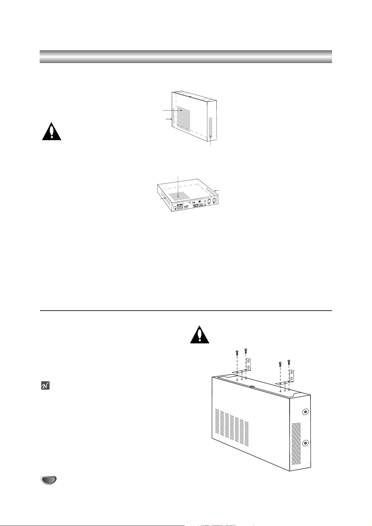
Ventilation / Installation Overview
The LST-5600A Integrator Box as well
as Plasma monitors generate heat during operation and need to be provided
with adequate ventilation to assure continued reliable operation. See recommendations below.
Ventilation Clearance
Proper clearance for air to
flow around the LST-5600A
Integrator Box must be provided.
Monitor Ventilation
Be sure proper ventilation is provided
for the monitor, see monitor installation
guide for specified ventilation requirements.
1. There are ventilation holes on three
sides of the the LST-5600A box provided for ventilation cooling.
a. If the box is mounted vertically,
the vents on the sides should be
located on the top and bottom
for free vertical air movement.
b. If the box is mounted horizontal-
ly, the vents should be located at
the sides and top of the enclosure (never mount the box with
vents facing down).
2. The vent holes should never be
blocked or obstructed to airflow but
have an unimpeded path through
any enclosure back to room temperature air.
3. The unit and its venting, should
not be installed near heat sources
such as radiators or heating ducts.
4. If the unit is placed in an enclosure, tests should be run to confirm that the ambient temperature
around the unit under normal
expected operating conditions is
stable and does not exceed 40
degrees Celsius (104F). This can
be determined by placing a thermometer near the air intake vents
in the proposed enclosure and
measuring the temperature every
hour, under normal operating conditions, until two successive readings repeat. If temperature does
not stabilize but keeps increasing
above 104F, ventilation is inadequate and needs to be improved.
5. Always provide adequate air space
between the ventilation areas and
adjacent structures.
Note
In addition to the ventilation requirements shown, be sure to allow
enough clearance (4” - 5”) for wiring
clusters attached to the Integrator
Box.
Vertical Installation (Wall Mount) Using
Supplied Angled L-Brackets
Two angled L-brackets are provided so that the
Integrator Box can be mounted on a flat vertical surface, like a wall. Install the two angled L-brackets and
the screws provided.
Mount Integrator Box on the wall using four appropriate
screws.
ote
The brackets are designed to be mounted to typical 16”
spaced wall studs. Do not mount the Integrator Box to a
weak wall surface. If wall studs are not available, use
some other appropriate fastening system.
Monitor/Integrator Box Wall Mounting System
The plasma monitor and Integrator Box can be mounted
to a wall using an optional Monitor/Integrator Box wall
mounting system. For further information on the mounting system, see your LG dealer.
Ventilation Clearance
Proper clearance for air to flow around the
LST-5600A Integrator Box must be provided,
see above.
Vent Holes
Vent Holes
Vent Holes
Vent Holes
Vent Holes
Vent Holes
Page 7
INTRODUCTION
7
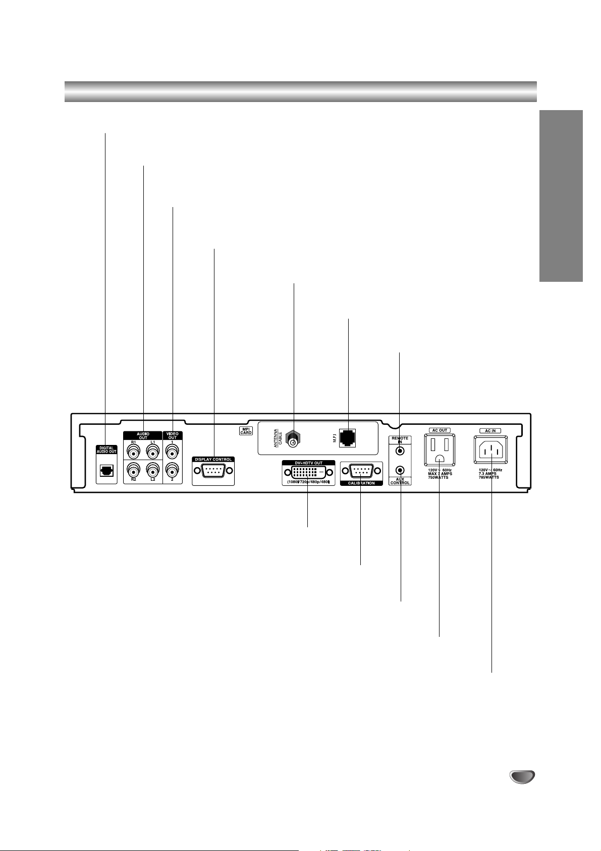
Connections Panel
Integrator Box AC POWER INPUT
Plug Integrator Box power cord here.
AC POWER OUTPUT
Plug viewing device power cord here.
AUX CONTROL CONNECTOR
Connect the AUX controller cable here.
CALIBRATION PORT
Connect Integrator Box configuration device (PC) here.
DVI-HDTV OUTPUT PORT
Connect DVI-HDCP compatible HD monitor here.
SIGNAL INPUT
Connect source signal to this input jack.
M.P.I. INPUT PORT
Connect clone programmer to this port.
REMOTE CONTROL IR
SENSOR CONNECTOR
Connect the remote IR sensor
here.
DISPLAY CONTROL JACK
Connect RS232 9-pin connector on the rear of the plasma panel here
VIDEO OUT 1, 2
Restricted to factory test use only.
AUDIO OUT (Left/Right) 1, 2
Connect to a TV, Amplifier, Receiver or Stereo System.
DIGITAL AUDIO OUT (OPTICAL)
Connect to digital (optical) audio equipment.
Page 8
8
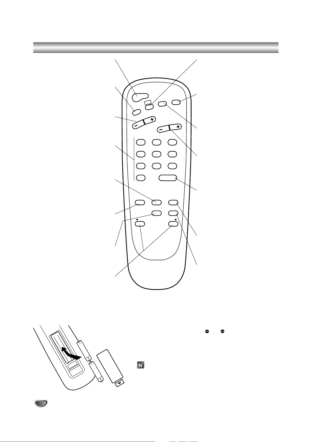
Typical Installer Remote Control Key Functions
POWER
Turns TV On and Off.
TV/FM (DOWN ARROW)
Down arrow selects menu options.
VOLUME (– / +)
Adjusts the sound level.
NUMBER KEYPAD
Selects channels directly and enters
numeric values for some options.
MENU
Displays on-screen menus for TV
mode.
TIMER
Displays the Sleep Timer menu.
Selects AM/PM in the alarm menu.
SELECT (UP ARROW)
Up arrow selects menu options.
LEFT/RIGHT ARROWS
Left/Right arrows adjust menu
options.
CC (Closed Captioning)
Displays the closed captions/text
menu.
MUTE
Turns sound Off and On while the
picture remains.
FLSHBK (FLASHBACK)
Returns to the last channel viewed.
CHANNEL (– / +)
Chooses next higher/lower available
channel.
ENTER
Shows the Channel/Time display.
Press after channel numbers for
instant channel selection.
Removes menus from screen.
ALARM
Displays the Alarm menu.
CH PREVIEW (SURF)
Shows the list of your surf channels.
Remote Control Operation
Point the Remote Control at the remote sensor and press the buttons.
Remote Control Battery Installation
Detach the battery cover on the rear of the Remote Control, and
insert two size AA batteries with and aligned correctly.
Caution:
Do not mix old and new batteries. Never install different types of
batteries such as standard, alkaline, etc.
otes
• The LST-5600A is operated by a user-supplied IR Remote
Control.
• The Remote Control shown on this page is a typical analog TV
remote. No remote control is provided with the LST-5600A. This
typical Installer remote control is shown for reference only.
POWER
FLSHBK
CC
TV/FM
VOLUME
123
456
789
0
TIMER MENU ALARM
ADJ ADJ
CHANNEL
ENTER
SELECT CH PREVIEW
MUTE
Page 9
INSTALLATION
9
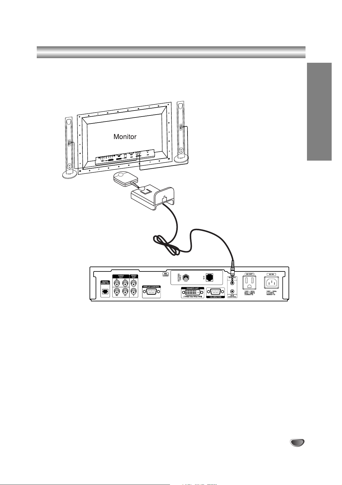
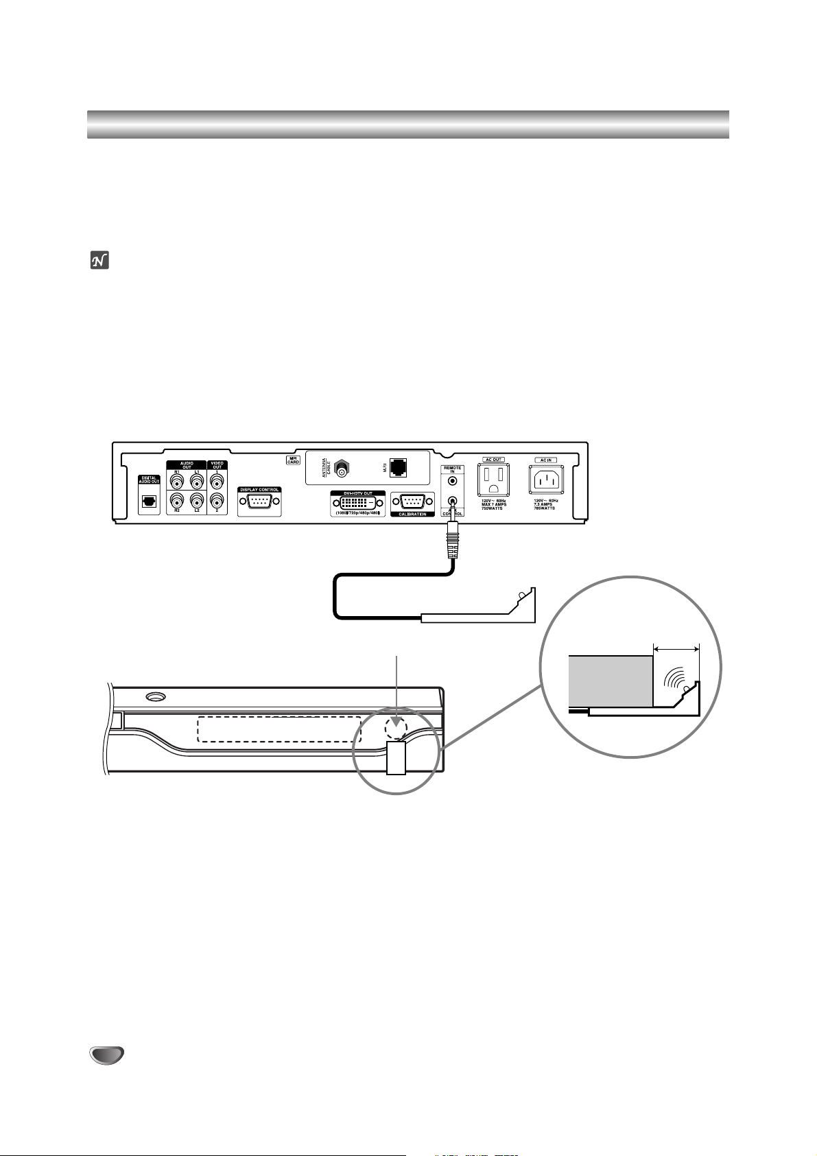
IR Receiver & IR Bracket Installation
Install the IR Receiver and Bracket Assembly to the back of the monitor using the method described below.
IR Receiver & Bracket Installation
The IR Receiver and mounting bracket are provided. Mount the IR Receiver on display panel with two-sided tape.
Choose the best location based on different positions in the room to assure that the IR signal from the end user
remote will be received by the IR sensor.
)
(+
L
)
(
)
(
R
)
(+
AC INPUT
)
IO
D
U
EXTERNAL SPEAKER (8
A
RL
2C
-23
S
R
AUDIO INPUT
R
P
B
YP
RGB-PC INPUT
)
VIDEO
O
)
N
O
(M
(VGA/SVGA/XGA/SXGA)
IO
D
AU
RL
COMPONENT(480i/480p
(DVD INPUT)
S-VIDEO
AV INPUT
IR Receiver
IR Bracket
Integrator Box Connection Panel
Page 10
10
AUX Controller: Connection and Placement
Connect the AUX Controller to allow the Integrator Box to operate your AUX device.
1
Connect the AUX Controller to the AUX CONTROL cord on the LST-5600A.
2
Place the AUX Controller under and in front of the AUX device. The AUX Controller must extend just out in front
of the infrared sensor on the AUX device.
ote
If the infrared sensor is not marked on your AUX device, shine a flashlight into the front panel of the AUX device to
locate the sensor.
Integrator Box Connection Panel
DVD (Front View)
AUX Controller
IR Sensor
DVD
(Side View)
1/2" to 1"
Page 11
INSTALLATION
11
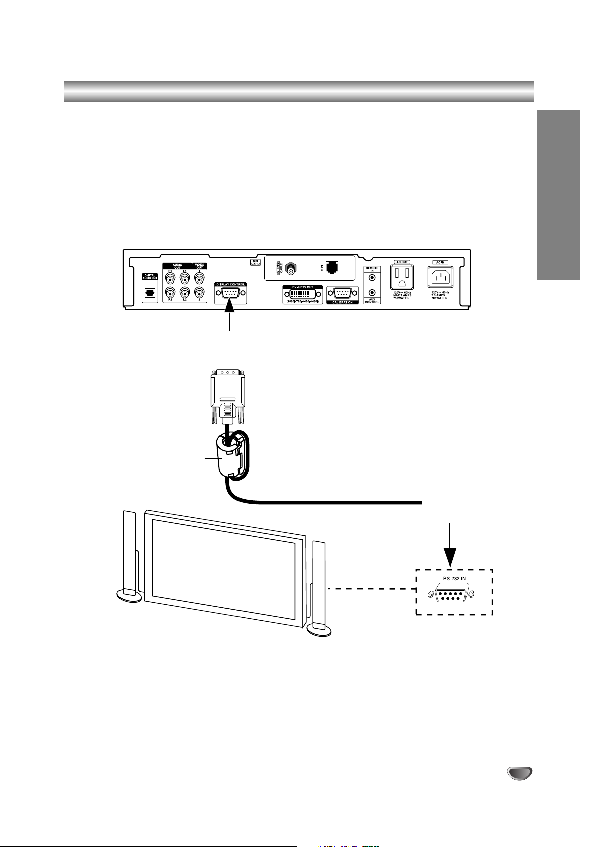
RS-232 Control Connections
Connect the Display Control (RS-232) port from the LST-5600A to the monitor and control the monitor functions with
RS-232 commands.
RS-232 Connections
1
Connect a digital Zenith/LG Monitor to the Display Control port, according to the diagram shown below.
2
Control the Monitor functions with RS-232 commands.
Integrator Box Connection Panel
From
Display Control
Port
Ferrite Core
(TDK, ZCAT2035-0930)
Typical Digital Monitor
To
RS-232 In
Port
Page 12
12
Equipment Connection Overview
The LST-5600A Integrator Box System is designed to be operated by an external device such as a Remote Control.
Integrator Box Output Image/Sound
The source image and sound can be seen and heard on an external monitor. A convenience AC power output is
also provided on the Integrator Box so that the external monitor viewing device can be powered directly by the
Integrator Box system.
Display Equipment
The back side connection panel of the Integrator Box unit has jacks provided for connecting a wide variety of A/V
equipment signal output formats. Some typical equipment options are shown below.
ote
The Video Out 1 and 2 jacks are restricted to factory test use only.
*HDCP
High-bandwidth Digital Content Protection
Audio
HD Monitor with HDCP*
(DVI-HDTV type)
Page 13
INSTALLATION
13
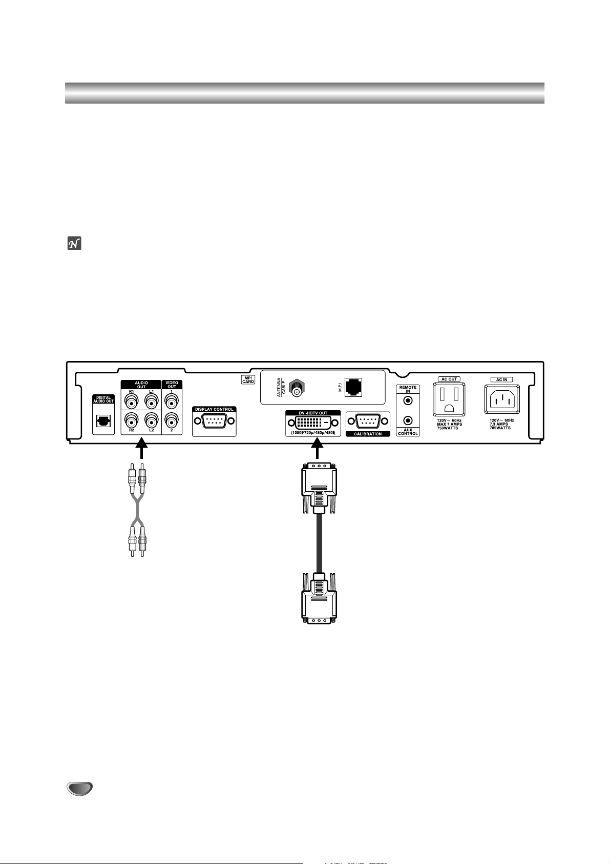
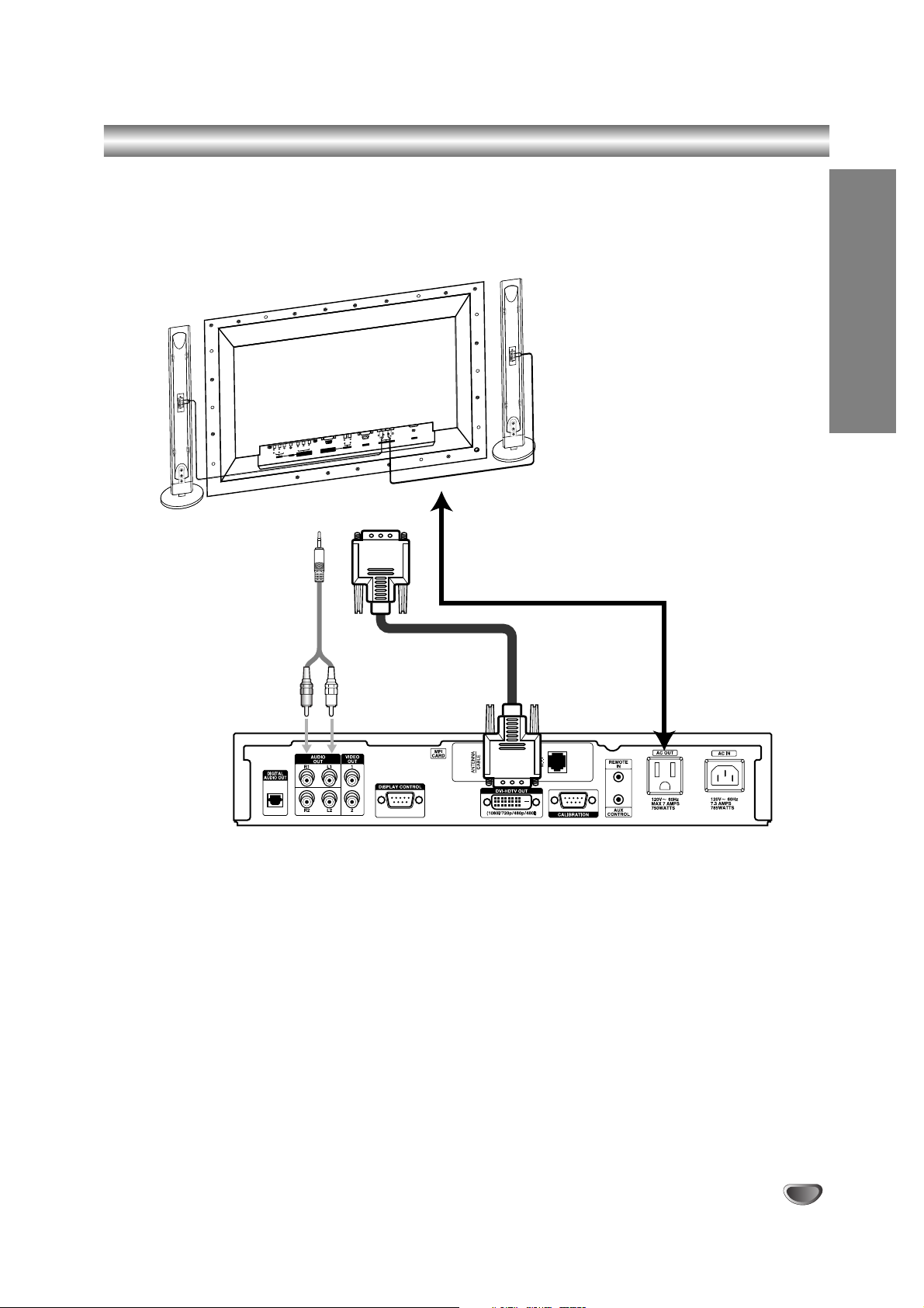
Observation Equipment Setup – DVI-HDTV (HDCP*) Video Output
Connect the DVI-HDTV Video Output from the Integrator Box to the device that you will use to view the signal. An
AC convenience power outlet is also provided on the Integrator Box so that the auxiliary viewing device can be
powered directly with the Integrator Box.
*HDCP
High-bandwidth Digital Content Protection
Monitor
)( )
(+
L
( )
R
)
(+
T
PU
IN
AC
)
R (8
E
EAK
SP
L
RNA
E
IO
D
U
EXT
A
RL
C
-232
RS
PUT
DIO IN
AU
R
P
B
PUT
PC IN
YP
B-
RG
)
A
XG
A/S
XG
A/
EO
VG
ID
/S
)
V
A
NO
G
O
(M
(V
80p)
IO
D
T(480i/4
U
A
RL
NEN
PO
M
CO
UT)
INP
VD
(D
DEO
S-VI
T
NPU
I
AV
Integrator Box Connection Panel
Page 14
14
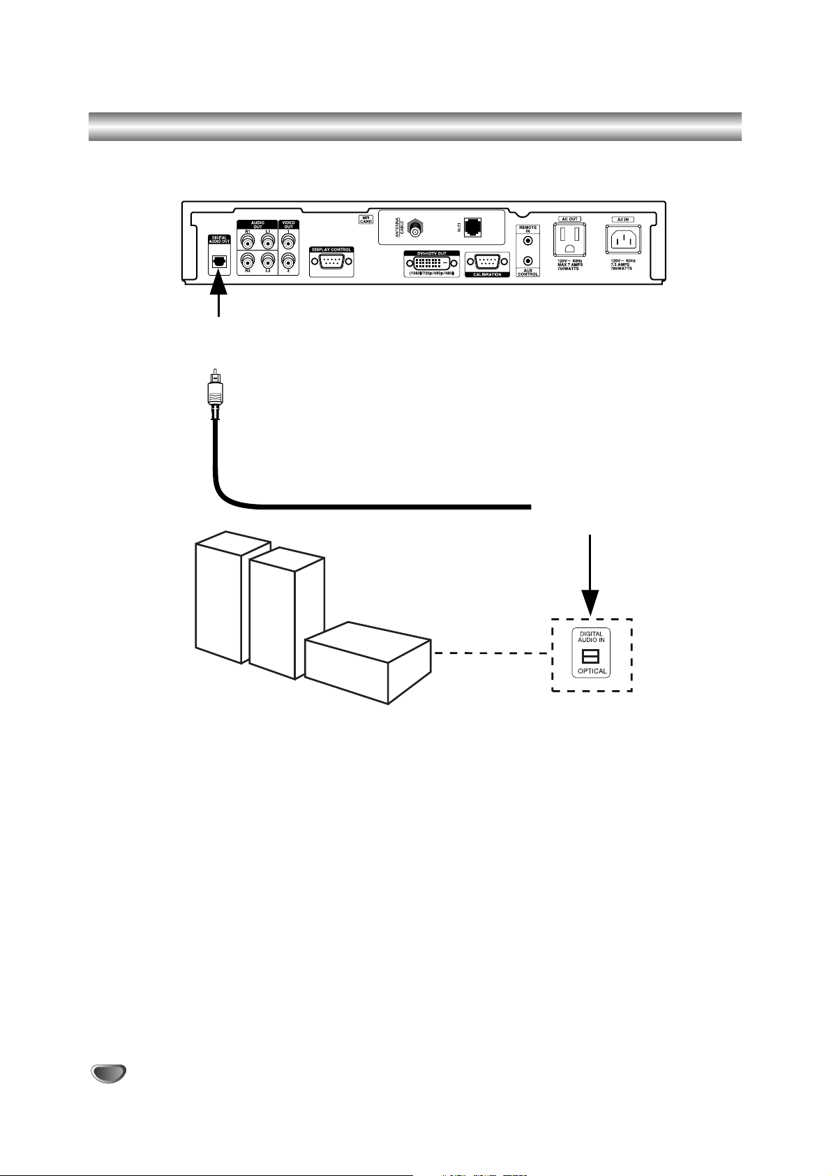
Audio Connection – Digital Audio Optical Connections
Digital Audio Optical Output Connections to External Amplifier
Hook up a Digital Audio Amplifier System using the Digital Audio Optical Out port, according to the diagram above.
Select the Digital Audio Optical input source on the Amplifier.
Integrator Box Connection Panel
From Digital Audio
Optical Out
Port
To
Digital
Audio Optical
In Port
Typical Digital Audio
Amplifier System
Page 15
INSTALLATION
15
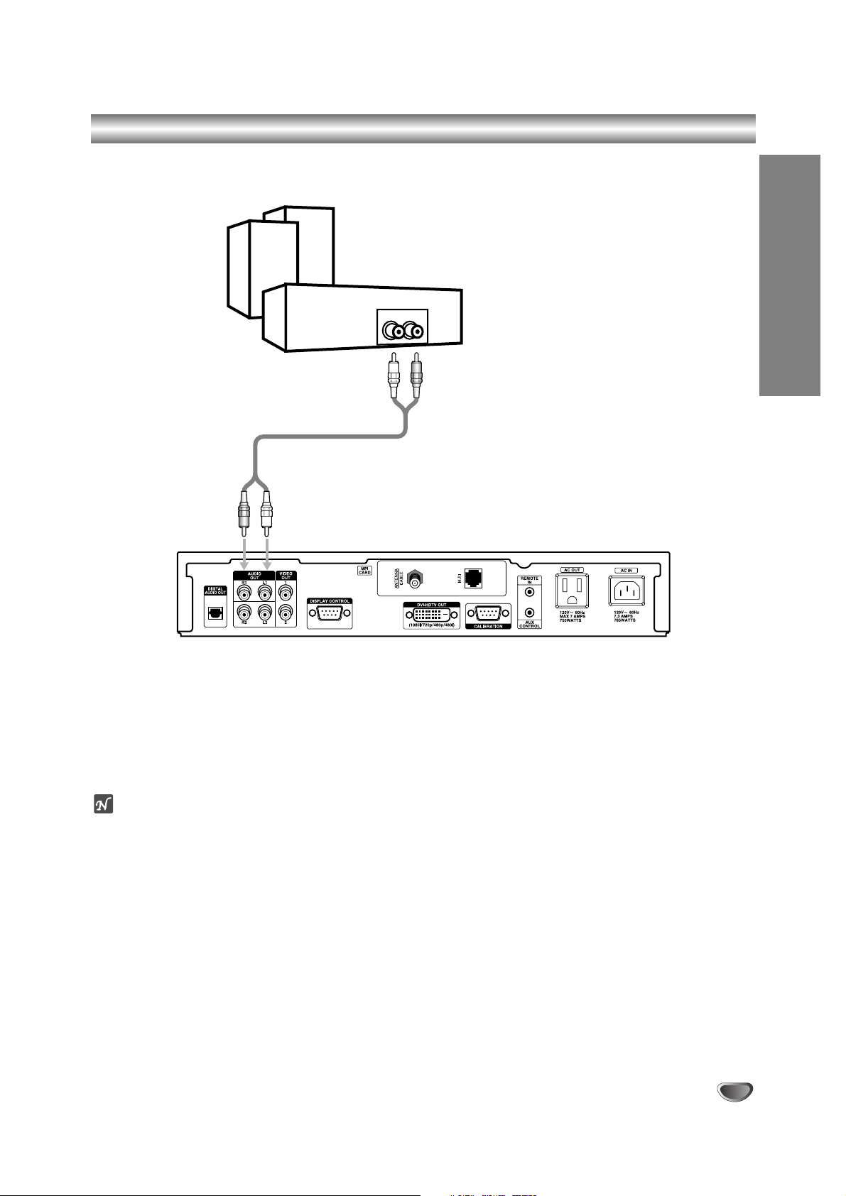
Audio Connection – Analog Hi-Fi System
Hi-Fi System Connections
Connect the Left and Right “AUDIO OUT” jacks from the Integrator Box to the Left and Right “INPUT” jacks on your
Hi-Fi Audio System.
ote
When viewing a digital broadcast with Dolby Digital® audio, you will be able to hear the broadcast’s audio from the
analog audio left and right jacks. However, a digital audio connection to a Dolby Digital Audio Receiver is required
to enjoy Dolby Digital audio with up to 5.1 channels.
Analog stereo amplifier
AUDIO IN
Integrator Box Connection Panel
Page 16
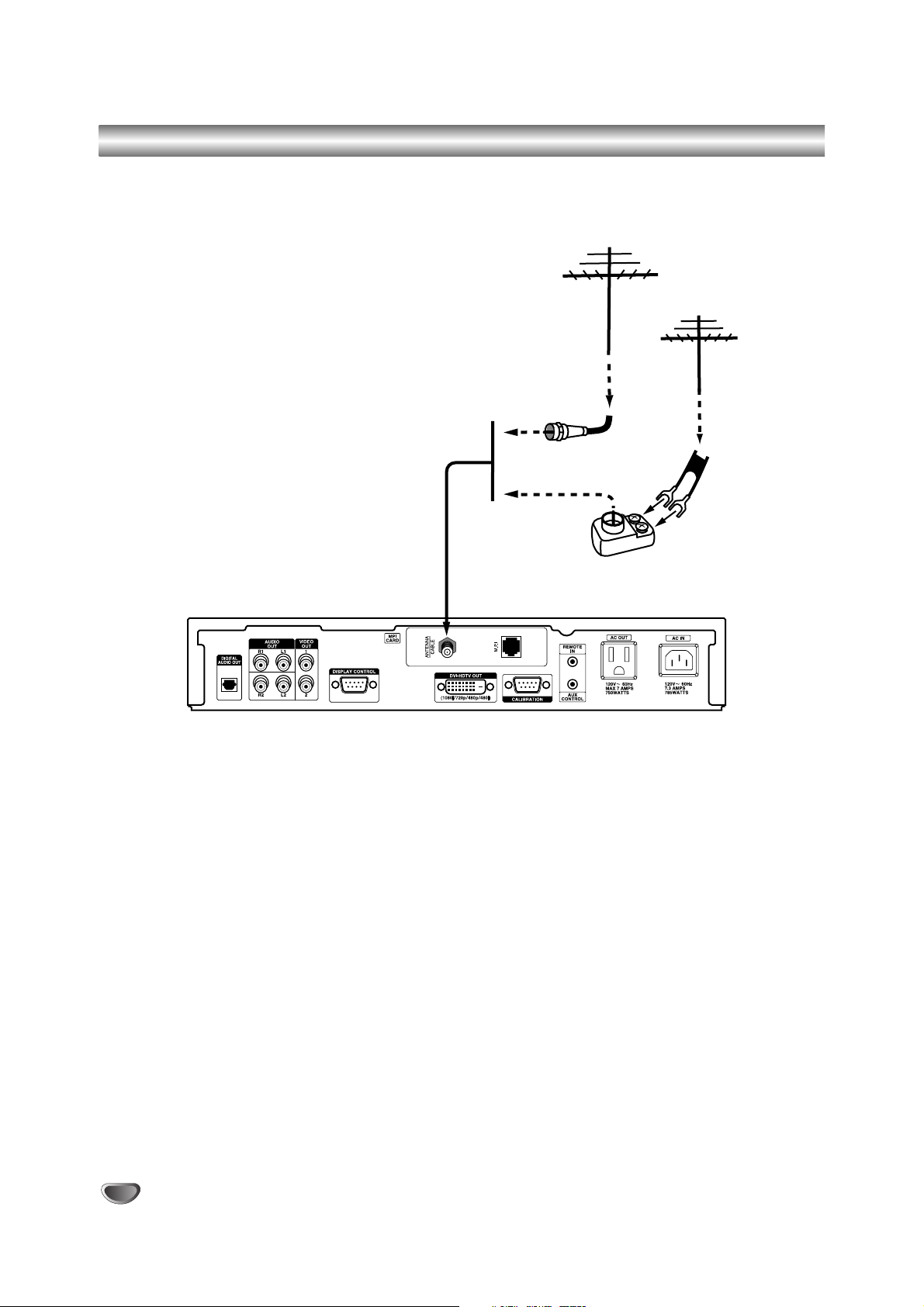
16
Over-the-air Antenna Signal Reception Setup
If the signal source is from an over-the-air antenna, connect the antenna to the Integrator Box system as shown
below.
Mini Glossary
75 OHM RF CABLE
The wire that comes from an off-air antenna or cable service provider. Each end looks like a hex shaped nut with a
wire sticking through the middle, and it screws onto the threaded jack on the back of your Integrator Box.
300 TO 75 OHM ADAPTER
A small device that connects a two-wire 300 ohm antenna to a 75 ohm RF jack (Antenna/Cable). These adapters
are usually about an inch long with two screws on one end and a round opening with a wire sticking out on the
other end.
Antenna
Antenna
RF Coaxial Wire
(75 ohm)
300/75 ohm
Adapter
Integrator Box Connection Panel
Page 17
INSTALLATION
17
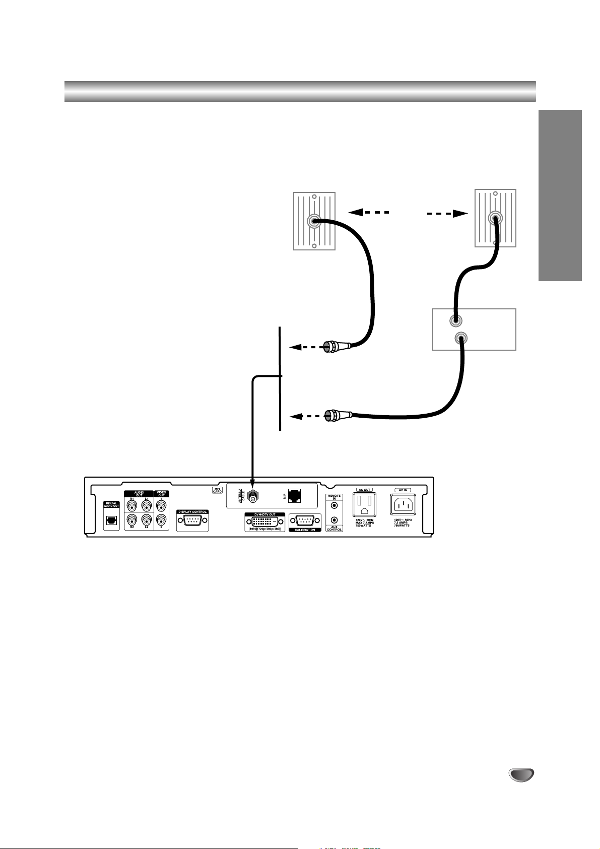
Cable Service Signal Reception Setup
If the signal source is from a cable source with or without a cable box, connect the cable service to the Integrator
Box system as shown below.
Cable TV
Wall Jack
RF Coaxial Wire
(75 ohm)
RF Coaxial Wire
(75 ohm)
Or
In
Out
Cable TV
Wall Jack
Typical
PPV System
Box
Integrator Box Connection Panel
Page 18

18
EZ Channel Scan (Channel Search)
Automatically finds all channels (both analog and digital) available through the antenna/cable input, and stores all
the active channels on the channel list. Inactive or weak channels may not appear on the list. The channel list created here can be seen in the Surf List/Ch. Edit menu.
To search for the available channels:
1
Press the MENU button on the Remote Control to display the on-screen menu.
2
Select the Setup menu by pressing “ENTER”.
3
EZ Channel Scan will be automatically highlighted.
4
Move the highlight to the right with “ADJ 22” to display the channel search menu box.
5
Select “Start” button and press “ENTER”. The scrolling yellow bar will indicate progress while scanning
the channels. After the scanning process begins, “Start” will change to “Next”. If you press “Next”, the
scanning of the current signal source will be ignored and the scanning of the next signal source will
proceed.
6
After channel scanning is complete, the channels found will be stored.
7
Press “ENTER” after the channel search is complete.
8
Press the “MENU” button on the Remote Control to exit the menu.
ote
The EZ Channel Scan feature will not available if Installer menu item 028 CH-OVERIDE is set to ‘0’. Set to ‘1’ to be able
to use EZ Channel Scan.
Page 19

OPERATION
19
Surf List / Ch. Edit
The default channel list is made in the EZ Channel Scan menu. Surf List/Ch. Edit allows you to create two other
types of channel lists; a custom list and a surf list. A custom list is created by toggling each channel on or off by
pressing “ENTER”.
Once a channel is highlighted, you will be able to see whether the channel is currently Added or Deleted by referring to the small window at the top-left corner of the screen.
To create your own Surf list, with up to 50 favorite channels, press the “CH PREVIEW (SURF)” button on the
Remote Control while a channel number is highlighted.
ote
The EZ Channel Scan feature will not available if Installer menu item 028 CH-OVERIDE is set to ‘0’. Set to ‘1’ to be able
to use EZ Channel Scan.
To edit the channel list:
1
Press the “MENU” button on the Remote Control to display the on-screen menu.
2
Select the Setup menu by pressing “ENTER”.
3
Scroll down to Surf List/Ch. Edit using “TV/FM (DOWN ARROW)”.
4
Press “ADJ 22” to display the channel editing screen.
To create a custom list:
1. Use “SELECT (UP ARROW), TV/FM (DOWN ARROW), 11ADJ, ADJ 22” to move the highlight on the channel
editing menu.
2. Choose “Added” or “Deleted” by pressing “ENTER” repeatedly.
The screen shown at the top left will indicate if the highlighted channel is shown or hidden.
To c reate a Surf list:
1. Use “SELECT (UP ARROW), TV/FM (DOWN ARROW), 11ADJ, ADJ 22” to move the highlight on the channel
editing menu.
2. Choose “Surf” or “No Surf” using the “CH PREVIEW (SURF)” button on the Remote Control.
3. Press the “MENU” button to return to the previous menu or press several times to remove menu.
Page 20

20
Clock Setup - Set the Clock Manually
Enables you to set the time manually.
To set clock manually:
1
Press the “MENU” button on the Remote Control to display the on-screen menu.
2
Select the Setup menu by pressing “ENTER”.
3
Scroll down to Clock using “TV/FM (DOWN ARROW)”.
4
Move the highlight to the right with “ADJ 22”.
5
Use “SELECT (UP ARROW), TV/FM (DOWN ARROW)” to move the highlight within the entry boxes.
6
Set the Year, Date and Time using the number buttons on the Remote Control.
7
Select the AM/PM option using “ADJ 22” button on the Remote Control. Use TIMER to set either AM or
PM.
8
Press “MENU” button to return to the previous screen or TV viewing.
Page 21

OPERATION
21
Audio Setup - Digital Output
Digital Output
If you are using an external Audio System that supports Dolby Digital® audio, select Dolby Digital audio mode. If
you are using an external Audio System that has a PCM only decoder, select PCM (Digital). If you are not using an
external Audio System, select OFF.
Do not select the Dolby Digital setting if connected to an Audio System that is not capable of decoding Dolby
Digital audio. Doing so may cause the Audio Receiver to create high-pitched noise that could potentially cause
harm to audio equipment.
To set the digital audio mode:
1
Press the “MENU” button on the Remote Control to display the on-screen menu.
2
Scroll down using “TV/FM (DOWN ARROW)” on the Remote Control and highlight AUDIO.
3
Select the Audio menu by pressing “ENTER”.
4
Digital Output will be highlighted automatically.
5
Move the highlight to the right with “ADJ 22”.
6
Use “SELECT (UP ARROW), TV/FM (DOWN ARROW)” to move the highlight within the entry boxes.
7
Select one of the three options and press “ENTER” to return to the previous menu.
8
Press the “MENU” button on the Remote Control to exit the menu.
PCM (Digital)
Pulse Code Modulation (PCM) decoders support L/R stereo only. If selected, audio outputs are decoded and transmitted to the Digital Output (SPDIF) in PCM mode.
Dolby Digital
®
Audio
Dolby Digital
®
audio, formerly known as AC-3 (Audio Coding 3rd Generation) or 5.1 channel audio, is a coding technique that provides up to five independent, full frequency response audio channels and one low frequency bass
channel.
ote
Please make sure that your A/V Amplifier supports Dolby Digital decoding, not all A/V Amplifiers support 5.1 decoding.
Page 22

22
Audio Setup - Audio Mode
Audio Mode
Sets the default audio mode when a program is broadcast in analog format. If you view a program that is broadcast
in mono, you will hear only mono sound, even though stereo mode may be set. If Second Audio Program “SAP”
mode is set, the program’s second audio program is broadcast in mono, if provided by the broadcaster.
To Set the Analog Audio Mode:
1
Press the “MENU” button on the Remote Control to display the on-screen menu.
2
Scroll down using “TV/FM (DOWN ARROW)” on the Remote Control to highlight AUDIO.
3
Select the Audio menu by pressing “ENTER”.
4
Scroll down to Audio Mode using “TV/FM (DOWN ARROW)”.
5
Move the highlight to the right with “ADJ 22”.
6
Use “SELECT (UP ARROW), TV/FM (DOWN ARROW)” to move the highlight within the entry boxes.
7
Select one of the three options and press “ENTER” to return to the previous menu.
8
Press the “MENU” button repeatedly on the Remote Control to exit the menu.
Page 23
OPERATION
23
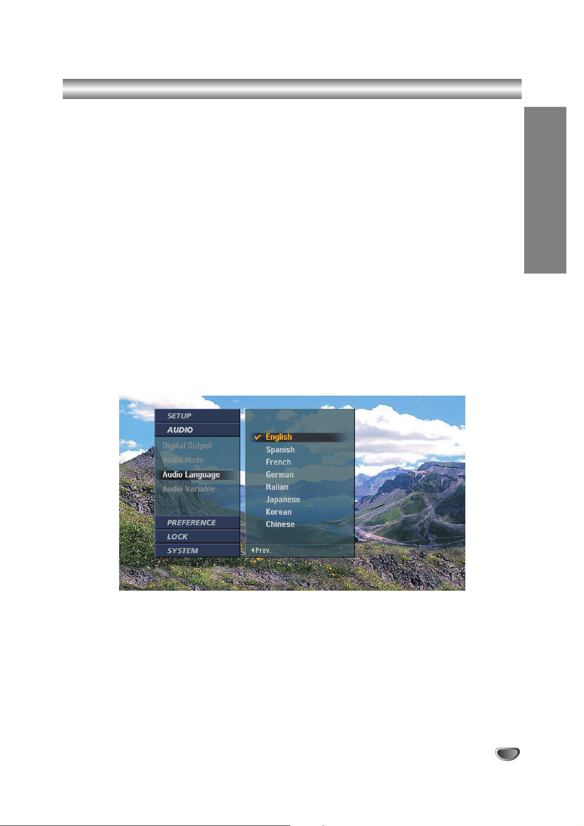
Audio Setup - Audio Language
Audio Language
If available, allows you to hear a program in other languages assuming that the program is broadcast in digital format.
While viewing a program, you may select any language available on the audio language box in the channel banner
and pressing “SELECT (UP ARROW) or TV/FM (DOWN ARROW)” repeatedly to select the desired language.
To set the digital audio language:
1
Press the MENU button on the Remote Control to display the on-screen menu.
2
Scroll down using “TV/FM (DOWN ARROW)” on the Remote Control to highlight AUDIO.
3
Select the Audio menu by pressing “ENTER”.
4
Scroll down to Audio Language using “TV/FM (DOWN ARROW)”.
5
Move the highlight to the right with “ADJ 22”.
6
Select one of the eight language options and press “ENTER” to return to the previous menu.
7
Press the MENU button repeatedly on the Remote Control to exit the menu.
Page 24

24
Audio Setup - Audio Variable Sound Output
Audio Variable
Set up volume level control with the Remote Control or turn off for fixed audio output.
To set Audio Variable:
1
Press the MENU button on the Remote Control to display the on-screen menu.
2
Scroll down using “TV/FM (DOWN ARROW)” on the Remote Control to highlight AUDIO.
3
Select the Audio menu by pressing “ENTER”.
4
Scroll down to Audio Variable using “TV/FM (DOWN ARROW)”.
5
Move the highlight to the right with “ADJ 22”.
6
Select “On” or “Off” and press “ENTER” to return to the previous menu.
On: Volume level is controlled with the Remote Control.
Off: Volume level is not controlled by the Remote Control.
7
Press the MENU button repeatedly on the Remote Control to return to TV viewing.
Page 25

OPERATION
25
Aspect Ratio Setup - I
Choosing the Aspect Ratio
Selects the screen format. When you view a high-definition picture using the video 480i or 480p output format, you
can choose Letterbox, Cropped or Squeezed.
When you view a standard-definition picture using the 720p or 1080i output format, you can choose Normal, Wide,
Panorama, Zoom or Cine-Zoom. When you view a high-definition picture using the 720p or 1080i output format, you
can temporarily choose Standard, Expand, Shrink.
Choosing the screen format output for the viewing device:
1
Press the MENU button on the Remote Control to display the on-screen menu.
2
Scroll down using “TV/FM (DOWN ARROW)” on the Remote Control to highlight PREFERENCE.
3
Select the Preference menu by pressing “ENTER”.
4
TV Aspect Ratio will be automatically highlighted.
5
Move the highlight to the right with “ADJ 22”.
6
Select one of the options and press “ENTER” to return to the previous menu.
7
Press the MENU button on the Remote Control to exit the menu.
Page 26

26
Aspect Ratio Setup - II
Options for viewing (16:9) high-definition content WHEN OUTPUT FORMAT IS 480i OR 480p MODE :
Letter Box
Use to show a picture with an original 16:9 aspect ratio (in a wide format). Letterbox mode will shrink the picture to
fill the screen, with black (or gray) bars appearing at the top and bottom of the screen.
Cropped
Use to show a picture filling the entire screen by cropping (removing) the left and right portions of the picture.
Squeezed
Use to show a full picture filling the entire screen with no black/gray bars. The picture in a 16:9 format will be horizontally adjusted or squeezed to fit the 4:3 ratio monitor.
Options for viewing (4:3) content on a wide TV (16:9) display WHEN OUTPUT FORMAT IS 720p OR 1080i
MODE:
Normal
Use to show a picture with an original 4:3 aspect ratio on your 16:9 Monitor, with black/gray bars appearing at the
left and right sides.
Wide
Use to show a picture adjusted horizontally (in a linear proportion) to fill the entire screen.
Panorama
Use to show a picture adjusted in a non-linear proportion (more at both sides) to create a spectacular view.
Zoom
Use when you want to fill the entire screen with no black/gray bars appearing. The image will be altered both horizontally (stretched) and vertically (cropped). The top and bottom portions of the picture will be cut.
CINE-Zoom
Use to adjust zooming. The picture can be adjusted in multiple steps to provide the best display for many program
formats on your display device.
Options for viewing (16:9) high-definition content WHEN OUTPUT FORMAT IS 720p OR 1080i MODE :
(Note: You may choose one of three picture appearance options.)
Standard
Choose when you want to view a picture with no adjustments.
Expand
Choose when you want to view a picture in the 16:9 ratio. The picture will be horizontally adjusted or expanded to fit
16:9 ratio size. Left and right portions of the picture will not be shown.
Shrink
Choose when you want to view a picture in the 4:3 ratio. The picture will be horizontally adjusted or squeezed to fit
4:3 ratio size. Black or gray bars will show at the left and right side.
otes
• The aspect ratio setting changes both the high-definition outputs (DVI-HDTV) and the standard-definition outputs
(Video 1/2).
• The Video Out 1 and 2 jacks are restricted to factory use only.
Program Format Output Format Available Aspect Ratios
SD (480i/p) 4:3 SD (480i/p) 4:3 No Adjustment Options
HD (720p/1080i) 16:9 SD (480i/p) 4:3 Letter Box, Cropped, Squeezed.
SD (480i/p) 4:3 HD (720p/1080i) 16:9 Five Aspect Ratio controls: (Normal, Wide, Panorama,
Zoom, Cine-Zoom).
HD (720p/1080i) 16:9 HD (720p/1080i) 16:9 Three temporary Aspect Ratio controls: (Standard, Expand,
Shrink).
Page 27

OPERATION
27
Digital Caption Setup
Digital Captions Setup
Select a mode for displaying Digital Caption Data. In the Digital Caption Service, Services 1-6 typically offer different
Language Services, if available.
Service 1
Service 1 is designated as the Primary Caption Service. This service contains exactly as spoken, captions for the
primary language being spoken in the accompanying program’s audio.
Service 2
Service 2 is designated as the Secondary Language Service. This service contains captions in a secondary language that are translations of the captions in the Primary Caption Service.
Services 3-6
The other services are not pre-assigned. It is at the discretion of the individual caption provider to provide the
remaining service channels.
To set up DTV Captions:
1
Press the MENU button on the Remote Control to display the on-screen menu.
2
Scroll down using “TV/FM (DOWN ARROW)” on the Remote Control to highlight PREFERENCE.
3
Select the Preference menu by pressing “ENTER”.
4
Scroll down to DTV Caption using “TV/FM (DOWN ARROW)”.
5
Move the highlight to the right with “ADJ 22”.
6
Select one of the options and press “ENTER” to return to the previous level.
7
Press the MENU button on the Remote Control to exit the menu.
ote
If both digital captions and analog closed captions are chosen, then only digital captions will be selected.
Digital captions can also be selected using the CC button on the Remote Control.
Page 28
28
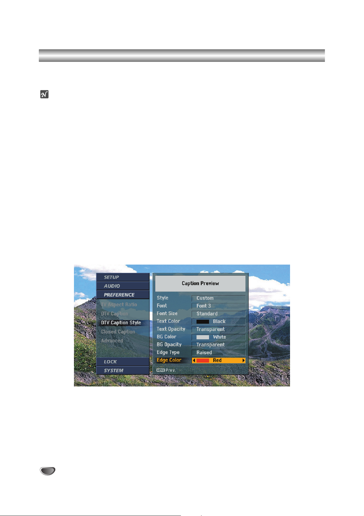
Digital Caption Style Setup
Digital Caption Style Setup
Customize the caption style by selecting: Font, Edge, Type, Color, etc.
ote
If the Style setting is “Set By Program” the captions will appear as defined by the program provider.
To set up DTV Caption Style:
1
Press the MENU button on the Remote Control to display the on-screen menu.
2
Scroll down using “TV/FM (DOWN ARROW)” on the Remote Control to highlight PREFERENCE.
3
Select the Preference menu by pressing “ENTER”.
4
Scroll down to DTV Caption Style using “TV/FM (DOWN ARROW)”.
5
Move the highlight to the right with “ADJ 22” to move to the caption style box.
6
Select each option from Style to Edge Color.
Move the highlight using “SELECT (UP ARROW), TV/FM (DOWN ARROW)”, and select a value for each
option with “11ADJ, ADJ 22”.
7
Press the MENU button repeatedly on the Remote Control to return to the previous level or exit the
menu.
Page 29

OPERATION
29
Closed Captions Setup
Setting Closed Captions
Selects the mode for displaying analog Closed Caption Data. In the Analog Caption Service, Captions 1-4 display a
program’s dialog, and Text 1-4 display data service information.
(Note : Closed Captions will only appear if they are provided by the broadcaster.)
Caption 1
Caption 1 is the primary caption service that synchronizes the captioning language with the sound. This method is used by most
broadcasters.
Caption 2
Caption 2 is the special non-synchronous caption service that does not need to be in sync with the sound and may provide simplified captioning, which is usually delayed.
Caption 3
Caption 3 serves as an alternate captioning service channel. Captioning is often a secondary language translation such as
French, Spanish, simplified English or displayed at a slower rate.
Caption 4
Caption 4 is another special non-synchronous caption service that does not need to be in sync with the sound and may provide
simplified captioning, usually delayed.
Text 1-4
Text 1-4 usually displays information at the bottom screen position and is used for a data service, generally not program-related.
To set up Closed Captions:
1
Press the MENU button on the Remote Control to display the on-screen menu.
2
Scroll down using “TV/FM (DOWN ARROW)” on the Remote Control.
3
Select the Preference menu by pressing “ENTER” to highlight PREFERENCE.
4
Scroll down to Closed Caption using “TV/FM (DOWN ARROW)”.
5
Move the highlight to the right with “ADJ 22”.
6
Select one of options then press “ENTER” to return to the previous menu.
7
Press the MENU button repeatedly on the Remote Control to exit the menu.
ote
If both digital captions and analog closed captions are chosen, then only digital captions will be selected. Closed
captions can also be selected using the CC button on the Remote Control.
Page 30

30
Advanced Setup
Advanced Setup
Configures special settings such as the background matte color for wide aspect ratio programming, the channel
banner time-out period, and the contrast range for DVI output.
To set up Advanced menu options:
1
Press the MENU button on the Remote Control to display the on-screen menu.
2
Scroll down using “TV/FM (DOWN ARROW)” on the Remote Control to highlight PREFERENCE.
3
Select the Preference menu by pressing “ENTER”.
4
Scroll down to Advanced using “TV/FM (DOWN ARROW)”.
5
Move the highlight to the right with “ADJ 22”.
6
Select your default background Matte Color which appears with certain aspect ratio settings with
“11ADJ, ADJ 22”.
Or
Select a time-out duration for the Information banner either “Short” or “Long”.
Or
Select a Banner style: “Small” or “Medium” to be displayed when changing channels or pressing the
INFO button.
Or
Select a DVI Level: “Standard” which is recommended for most TVs or “Expand” which is
recommended for most digital monitors.
Or
Select EZ DVI: “On” or “Off”
7
Press the MENU button on the Remote Control to return to the previous menu or press MENU again to
exit the menu.
ote
In EZ DVI mode, the preferred resolution format for the DVI-HDTV monitor’s output display format is automatically
adopted. The format may be converted from the original broadcast format. The EZ DVI mode is only available if a
DVI-HDTV compatible monitor is connected to the receiver.
Page 31

OPERATION
31
Lock Setup – Lock System
Lock System (Parental Control)
Allows the end-user to set up viewing restrictions based on the program ratings. Access to the Lock System menu
is controlled by a password. The password can be changed if necessary each time the menu is displayed. Once a
program blocking scheme is set up, it can be turned on or off to restrict programming that can appear on the TV, or
not restrict programming.
To activate or deactivate the Lock System:
1
Press the MENU button on the Remote Control to display the on-screen menu.
2
Scroll down using “TV/FM (DOWN ARROW)” on the Remote Control to highlight LOCK.
3
Select the Lock menu by pressing “ENTER”.
4
If unlocked, Lock System will be automatically highlighted, otherwise requires that the end-user enter
the password.
To lock the system:
1. Move the highlight to the right with “ADJ 2” in Lock On/Off box.
2. Switch On or Off by using “ADJ 2”. Whenever you switch the lock system on, you need to enter the pass-
word as a reminder.
To set a password:
1. Move the highlight to the Set Password option using “TV/FM (DOWN ARROW)”.
2. Enter the password with the number buttons on the Remote Control.
3. Enter the password again for verification.
5
Press “11ADJ” to return to the previous screen or press the MENU button repeatedly on the Remote
Control to exit the menu.
Page 32

32
Lock Setup – Block Channel
Block Channel
Blocks any channels that the end-user does not want to view or does not want children to watch.
If the end-user tunes in a blocked channel, a pop-up will appear. The end-user will have to enter the correct password to view the channel.
If the Integrator Box is turned off then on, Block Channel will be automatically reactivated.
To block channels:
1
Press the MENU button on the Remote Control to display the on-screen menu.
2
Scroll down using “TV/FM (DOWN ARROW)” on the Remote Control to highlight LOCK.
3
Select the Lock menu by pressing “ENTER”.
4
Scroll down to Block Channel using “TV/FM (DOWN ARROW)”.
5
Move the highlight to the right with “ADJ 22”.
6
Select “On” or “Off” and press “ENTER” to return to the previous menu.
On: The current channel is blocked.
Off: The current channel is not blocked.
7
Press the MENU button repeatedly on the Remote Control to return to TV viewing.
ote
If the end-user tunes to a blocked channel, a password is required to view the channel. The Channel Block feature
should not be used as the only parental control. Since station assignments may change from time to time, controls
such as rating should always be used as the primary parental control. Additionally, the Channel Block settings may
be reset if there is an interruption to the AC power (such as if set is unplugged or there is a power failure).
Page 33

OPERATION
33
Lock Setup – Movie Ratings
Movie Rating
Blocks movies so children cannot view certain movies according to the movie ratings limit, as defined by the Motion
Picture Association of America. You can set the ratings limit by blocking out all the movies with the ratings above a
specified level. Keep in mind that the movie ratings limit applies only to movies shown on TV, not TV programs such
as soap operas.
To block movie programs:
1
Press the MENU button on the Remote Control to display the on-screen menu.
2
Scroll down using “TV/FM (DOWN ARROW)” on the Remote Control to highlight LOCK.
3
Select the Lock menu by pressing “ENTER”.
4
Scroll down to Movie Rating using “TV/FM (DOWN ARROW)”.
5
Select the level you want using “SELECT (UP ARROW), TV/FM (DOWN ARROW)” and press “ENTER” to
return to the previous menu.
MOVIE/MPAA rating
G: General Audiences. Viewing permitted for all ages.
PG: Parental Guidance Suggested. Some material may not be suitable for children.
PG-13: Parents Strongly Cautioned. Some material may not be appropriate for children under 13.
R: Restricted Under 17 requires parent or adult guardian present.
NC-17: No viewers 17 and younger.
X: No viewers 17 and younger.
6
Press the MENU button on the Remote Control repeatedly to exit the menu.
ote
The Lock feature relies on correct rating information to be provided by broadcasters and service providers. If broadcast rating information is missing or incorrect, the Lock feature cannot function as intended.
Page 34

34
Lock Setup – TV Rating-Children
TV Rating for Children’s Programs
Keeps children from watching certain children’s TV programs according to the ratings limit as defined by the TV
Parental Guidelines Monitoring Board. This rating applies only to TV programs for children. Unless you block TV
programs intended for mature audiences in the TV Rating–General menu, children may view those programs.
To block TV programs:
1
Press the MENU button on the Remote Control to display the on-screen menu.
2
Scroll down using “TV/FM (DOWN ARROW)” on the Remote Control to highlight LOCK.
3
Select the Lock menu by pressing “ENTER”.
4
Scroll down to TV Rating-Children using “TV/FM (DOWN ARROW)”.
5
Select Age or Content, if you want to lock a TV program based on age or content.
6
Select the level you want using “SELECT (UP ARROW), TV/FM (DOWN ARROW)” and press “ENTER” to
return to the previous menu.
TV Rating Children Programs
TV-Y: All Children. This program is designed to be appropriate for all children.
TV-Y7: Directed to Older Children. This program is designed for children age 7 and older.
7
Press the MENU button on the Remote Control repeatedly to exit the menu.
ote
The Lock feature relies on correct rating information to be provided by broadcasters and service providers. If broadcast rating information is missing or incorrect, the Lock feature cannot function as intended.
Page 35

OPERATION
35
Lock Setup – TV Rating-General
TV Rating for General Programs
Blocks TV programs, based on the rating scheme defined by the TV Parental Guidelines Monitoring Board.
To block TV programs:
1
Press the MENU button on the Remote Control to display the on-screen menu.
2
Scroll down using “TV/FM (DOWN ARROW)” on the Remote Control to highlight LOCK.
3
Select the Lock menu by pressing “ENTER”.
4
Scroll down to TV Rating-General using “TV/FM (DOWN ARROW)”.
5
Select Age or Content, if you want to lock a TV program based on age or content.
6
Select the level you want using “SELECT (UP ARROW), TV/FM (DOWN ARROW)” and press “ENTER” to
return to the previous level.
TV Rating for General Programs
TV-G: General Audiences. Most parents would find this program suitable for all ages.
TV-PG: Parental Guidance Suggested. This program contains material that parents may find unsuitable for
younger children.
TV-14: Parents Strongly Cautioned. This program contains some material that many parents would find unsuitable for children under 14 years of age.
TV-MA: Mature Audiences Only. This program is specifically designed to be viewed by adults and therefore
may be unsuitable for children under 17.
7
Press the MENU button on the Remote Control repeatedly to exit the menu.
Page 36
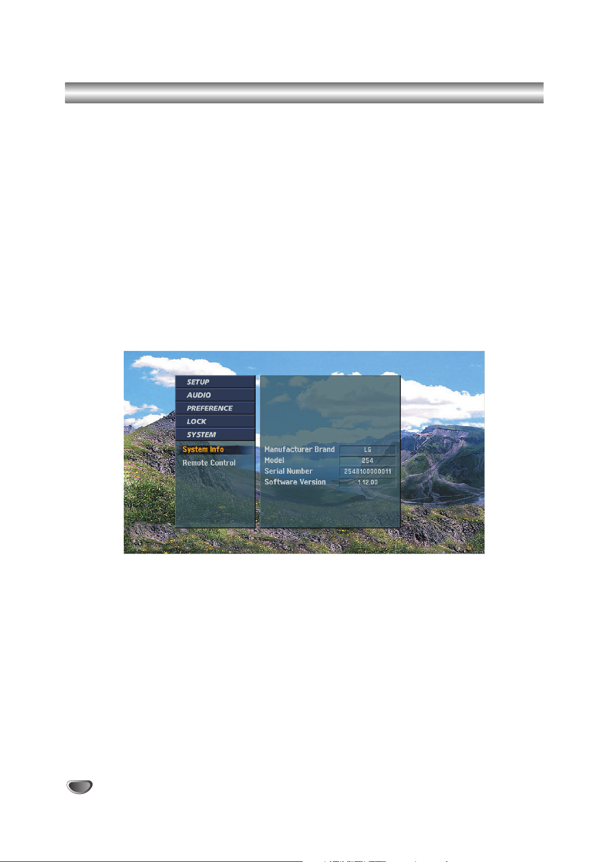
36
System Information
System Information
Shows system information about the LST-5600A Integrator Box.
To view System information about the HD receiver:
1
Press the MENU button on the Remote Control to display the on-screen menu.
2
Scroll down using “TV/FM (DOWN ARROW)” on the Remote Control to highlight SYSTEM.
3
Select the System menu by pressing “ENTER”.
4
System Info will be automatically highlighted.
5
Press the MENU button on the Remote Control repeatedly to exit the menu.
Page 37

OPERATION
37
Remote Control Setup
The LST-5600A Integrator Box can be set up to receive one of three types of Remote Control codes: DS5, SS7, or
SS6. The factory default code is DS5. You can also choose to assign one of the other codes.
To choose the Remote Control type:
1
Press the MENU button on the Remote Control to display the on-screen menu.
2
Scroll down using “TV/FM (DOWN ARROW)” on the Remote Control to highlight SYSTEM.
3
Select the System menu by pressing “ENTER”.
4
Scroll down to Remote Control using “TV/FM (DOWN ARROW)”.
5
Move the highlight to the right with “ADJ 2”.
6
Select one of options and press “ENTER” to set up and to return to the previous menu.
7
Press the MENU button on the Remote Control repeatedly to exit the menu.
Page 38

38
Installer Menus
Use the Installer Menu to set up or change operational settings. See detailed descriptions of the Installer items on
the following pages.
Accessing the Installer’s Menu
Installer’s menu items can be accessed by using the Installer’s Remote Control. To enter the installer’s menu, press
and release the MENU key repeatedly until the MENU key doesn’t work any more, then press 9,8,7,6, then ENTER.
To exit the Installer’s Menu, press ENTER again. Any changes you make will be stored in nonvolatile memory.
The Installer’s menu opens with item 000, INSTALLER. SEQ. Use the SELECT key to sequence through the available
menu items. Or, access an item directly by entering the line number, then pressing MENU. For example, to access the
Sleep Timer option which is on line 015, press 15, then MENU. To change a setting use the Left/Right ADJ keys.
Using the Installer’s Menu
Items 000 - 117 are immediately accessible only upon entering the Installer’s
Menu. Their numbers, descriptions, ranges, factory default settings, and a place
for listing any changes made on-site are given below and on the following
pages. A Factory Menu that is intended for qualified service technicians only, is
not shown. Normally Factory menu items do not require adjustment.
ote
Some Installer menu items may be revised or other items added for quality
improvement in the future. At the printing of this installation guide, the installer
menu items were as follows.
Installer Menu Items 000 through 117
Menu Item Function Value Range Default Value Brief Description of Function and Comments
000 INSTALLER SEQ 0-3 0 Set as required of system.
001 POWER MANAGE 0-7 0 Sets number of hours of no activity before auto shut off.
002 AC ON 0/1 0 Set to 1 to enable auto turn on at power up.
003 BAND/AFC 0-3 0 Selects Tuning band.
004 STRT CHANNEL 0-125, 255 255 Channel at turn-on (Set 255 to return to last Channel tuned).
005 CHAN LOCK 0/1 0 When set to 1, cannot tune from current channel.
006 NOT USED
007 STRT VOLUME 0-63, 255 255 Volume level at TV turn-on (Set 255 to retain last volume level).
008 MIN VOLUME 0-63 0 Minimum volume setting.
009 MAX VOLUME 0-63 63 Maximum volume setting.
010 MUTE DISABLE 0/1 0 Set to 1 to disable Mute function.
011 NOT USED
012 NOT USED
013 NOT USED
014 NOT USED
015 SLEEP TIMER 0/1 1 Set to 1 to enable Sleep Timer.
016 EN. TIMER 0/1 0 Set to 1 to enable On/Off Timers.
017 ALARM 0/1 1 Set to 1 to enable Alarm.
018 NOT USED
019 NOT USED
020 FEATURE LEVEL 0-2 1 Set as required of system.
021 V-CHIP 0/1 1 Set to 1 to enable V-Chip
022 MAX BLK HRS 0-99 12 Sets number of Parental Control blocking hours.
023 CAPTION LOCK 0/1 0 Set to 1 to retain caption setting at turn off.
LST-5600A INSTALLER MENU
000 INSTALLER SEQ 000
UPN: 000-000-000-000 FPGA 09F3
PTC V1.00.001 STB V2.0.00
Typical Installer Menu
Page 39

OPERATION
39
Installer Menus (Continued)
Menu Item Function Value Range Default Value Brief Description of Function and Comments
024 NOT USED
025 NOT USED
026 NOT USED
027 NOT USED
028 CH. OVERIDE 0/1 1 When set to 0, limits direct access to favorite channels.
029 OLD OCV 0/1 0 Set as required of system.
030 ACK MASK 0/1 0 MPI communication parameter.
031 POLL RATE 20-169 94 MPI communication parameter.
032 TIMING PULSE 186-227 207 MPI communication parameter.
033 NOT USED
034 NOT USED
035 COMPPORT EN. 0/1 1 If set to 1, enables display panel DVI input.
036 NOT USED
037 REAR Y/C EN. 0/1 1 If set to 1, enables display panel S-Video input.
038 YPrPb EN. 0/1 1 If set to 1, enables display panel Component input.
039 REAR AUX EN. 0/1 1 If set to 1, enables display panel Video input.
040 NOT USED
041 NOT USED
042 NOT USED
043 NOT USED
044 NOT USED
045 NOT USED
046 STRT AUX SRCE 1-4, 6, 255 255 Sets the starting AUX source
047 AUX STATUS 0/1 0 Set to 1 for MPI AUX source to be reported as
Channel number instead of Channel 0.
048 NOT USED
049 NOT USED
050 NOT USED
051 NOT USED
052 NOT USED
053 DIS. CH-TIME 0/1 0 If set to 1, disables Channel-Time display.
054 NOT USED
055 NOT USED
056 NOT USED
057 NOT USED
058 NOT USED
059 NOT USED
060 NOT USED
061 NOT USED
062 NOT USED
063 NOT USED
064 NOT USED
065 NOT USED
066 NOT USED
067 NOT USED
068 NOT USED
069 EN. CH-T COL. 0/1 1 Set to 1 to enable custom color for the Channel-Time display.
070 FOR. CH-TIME 0-7 2 Selects custom foreground color for the Channel-Time display.
Page 40

40
Installer Menus (Continued)
Menu Item Function Value Range Default Value Brief Description of Function and Comments
071 BCK. CH-TIME 0-7 2 Selects a custom background color for the Channel-Time display.
072 NOT USED
073 NOT USED
074 NOT USED
075 NOT USED
076 NOT USED
077 NOT USED
078 UPN MSB 0-255 0 User programmable number.
079 UPN MSB-1 0-255 0 User programmable number.
080 UPN MSB-2 0-255 0 User programmable number.
081 UPN LSB 0-255 0 User programmable number.
082 CHKSUM ERROR 0/1 1 If set to 0, does not check checksum
on MPI async port, SPI is always checked.
083 HANDSHAKE TIME 0-5 5 Lengthens MPI handshake response timeout.
Timeout = 25.5MS + (25.5MS* HANDSHAKE TIME)
084 PERMANENT BLK 0/1 0 If set to 1, makes V-Chip lockout time permanent.
085 NOT USED
086 NOT USED
087 REAR RGB EN. 0/1 1 If set to 1, enables RGB input.
088 NOT USED
089 NOT USED
090 NOT USED
091 NOT USED
092 NOT USED
093 NOT USED
094 NOT USED
095 NOT USED
096 NOT USED
097 NOT USED
098 NOT USED
099 NOT USED
100 NOT USED
101 NOT USED
102 ATSC BAND 0-4 4 Sets band.
103 ATSC TUNE MODE 0/1 1 0=Virtual, 1=Physical.
104 START MINOR CH 0-255 0 0=NTSC. Not. If not 0,=Minor Ch.
105 VID OUT FORMAT 0-3 0 Sets video output format: 0=108i, 1=720p, 2=480p, 3=408i.
106 ASP RATIO LOCK 0/1 0 0=Default Ratio on power up. 1=Retains Aspect Ratio on Power up.
107 BANNER 0-3 0 Selects appearance of Banner.
108 PANEL COM 0-4 3 0=1200, 1=2400, 2=9600, 3=115200, 4=IR Blaster.
109 PANEL HANDSHAKE 0/1 0 0=No handshake. 1=Handshake.
110PANEL DELAY 0-15 15 Sets panel delay time.
111 PANELVOL PRE 0-100 50 Preset panel volume to achieve the same
volume levels as other systems.
112PANEL STRT VOL 0-100 50 Panel start volume when on Aux. input.
113PANEL TYPE 0-3 0 See detailed descriptions
114PANEL MIN VOL 0-100 0 Sets display panel’s minimum volume level.
115PANEL MAX VOL 0-100 100 Sets display panel’s maximum volume level.
116 VIDEO MUTE EN 0/1 0 If set to 1, mutes video if no signal is present.
117FACT DEFAULT 0/1 0 0=Normal 1=Loads preset to all of above.
Page 41

OPERATION
41
Detailed Descriptions of Installer Menu Items
000 INSTALLER SEQUENCE
Gives access to Installer Menu depending on the code
selected.
0 = 9876 1 = 4321
2 = 1478 3 = 3698
001 POWER MANAGE (Power Management)
Determines hours of no activity before automatic shutoff. The POWER MANAGE function is for saving energy. If set to 0, Power Manage is OFF. Settings range
from 0 - 7, with 1 - 7 representing the hours that the
Integrator Box will remain on, unless there has been
activity from the Remote Control.
002 AC ON (AC Power Switchable)
Allows the Integrator Box to turn ON just by applying AC
power. Pressing the ON button is not necessary. This is
desirable if the Integrator Box is plugged into a cable
box or a power outlet controlled by a wall switch. Use
ADJ (Adjust) Left/Right to select 0 or 1, where 0 is the
default is OFF, and 1 is ON.
NOTE: If set to 1 (ON), the Integrator Box does not
respond to ON/OFF commands from the Remote
Control, and the SLEEP TIMER is also nonfunctional.
003 BAND/AFC (Band/Automatic Frequency Control)
There are 4 possible settings for this option:
0 = Broadcast 1 = CATV
2 = HRC 3 = IRC
004 STRT CHANNEL (Start Channel)
If active, this function allows you to determine the initial
channel number when the Integrator Box is turned ON.
This feature is useful for an in-house information channel, since the Integrator Box would always select that
channel when it is turned on. Setting this to 255 causes
the last channel viewed when Integrator Box was turned
off to be the tuned to channel when the Integrator Box
is turned on again.
255 = last channel 1-125 = channel number
0 = AUX
005 CHAN LOCK (Channel Lock)
CHAN LOCK is ideal if a cable box (or similar) is the
sole source for programming — and the TV must
always be on the same channel. Changing channels
with Channel Up/Down or keypad numbers is impossible. Channel Lock is inactive when set to 0 (default).
Generally, this feature is used in conjunction with
START CHANNEL (item 004.) where the start channel
may, for example, be set to 3 or 4. If the start channel is
3, then the TV will remain on channel 3.
006 NOT USED.
007 STRT VOLUME (Start Volume)
This function allows the Installer to determine the initial
volume level setting when the Integrator Box is turned
ON. This feature is useful for an in-house information
channel, since the Integrator Box would always select
that volume level when it is turned on. The range of
values are 0 - 63, 255. If 255 is selected, the current
volume level will be retained in memory when the
Integrator Box is turned off; at Integrator Box turn on,
volume level is automatically set to the last level.
008 MIN VOLUME (Minimum Volume)
This function determines the minimum volume level
allowable with the VOLUME (VOL) Up/Down control. In
this way, for example, someone cannot set the volume
too low to hear. The range is from 0 to 63—change values with ADJ (Adjust) Left/Right. The factory default is
0, which provides full range of volume control. It may be
best to set the same value on every Integrator Box.
NOTE: The minimum volume level cannot have a value
setting higher than in the MAX VOLUME level
(described below).
009 MAX VOLUME (Maximum Volume)
This function determines the maximum volume level
allowable with the VOLUME VOL Up/Down control. In
this way, for example, someone cannot set the volume
level high enough to disturb others. The range is 0 to
63, with 63 as the default which gives the user the full
range of volume control. Change values with ADJ
(Adjust) Left/Right. It may be best to set the same value
on every Integrator Box.
NOTE: The maximum volume level cannot have a value
setting lower than the MIN VOLUME level (described
above).
010 MUTE DISABLE
Enables or disables sound mute function. Set to 1,
sound cannot be muted. Set to 0, sound can be muted.
011 NOT USED
012 NOT USED
013 NOT USED
014 NOT USED
015 SLEEP TIMER
If set to 1, the SLEEP TIMER feature may be used (but
no message is displayed prior to turn-off). If set to 0, the
sleep timer is not available.
016 EN TIMER (Enables On-Off timers)
Set to 1, timer function is available to user. Set to 0 to
disable Timer functions. (Clock must be set in order to
use On/Off Timers.)
Page 42

42
Detailed Descriptions of Installer Menu Items (Continued)
017 ALARM
Gives you the option of making the alarm function available to the user. Set to 1, alarm function is available to
user. Set to 0 to disable the Alarm function.
Note: Clock must be set in order to set the Alarm.
018 NOT USED
019 NOT USED
020 FEATURE LEVEL
Default set to 1 for LG IR Remote Control operation.
Set 0, PLBL for LG Private Label IR Remote Control
operation. Set to 2 for NEC IR Remote Control operation.
021 V-CHIP
Set to 1 to activate V-Chip (Parental Control); have it
available to user to filter or control or restrict programming content. Set to 0 to turn V-Chip feature off, not
available to user; no programming restrictions can be
set.
022 MAX BLK HRS (Maximum Block Hours)
Set to 0 to 99 for the maximum V-Chip (Parental
Control) block hours. Default is 12 blocking hours.
023 CAPTION LOCK
If set to 1, caption state is retained through power cycle.
024 NOT USED
025 NOT USED
026 NOT USED
027 NOT USED
028 CH. OVERRIDE (Channel Override)
If set to 0, limits direct access tuning to favorite channel
list.
If set to 0, EZ Scan and Ch Edit menus are disabled.
029 OLD OCV (On Command VideoTM)
If set to 1, changes MPI operation for OCV.
030 ACK MASK
If set to 1, changes MPI for some OCV boxes.
031 POLL RATE
Selects poll rate for MPI. Step size of 16 MS.
032 TIMING PULSE
Sets baud rate for MPI. Step size of 4uS.
033 NOT USED
034 NOT USED
035 COMPPORT EN. (Compport Enable)
Set to 1 to enable the display panel DVI input.
Set to 0 to disable the display panel DVI input.
036 NOT USED
037 REAR Y/C EN. (Rear S-Video Enable)
Set to 1 to enable the display panel S-Video input.
Set to 0 to disable the display panel S-Video input.
038 YPrPb EN. (Y Pr Pb Enable)
Set to 1 to enable the display panel Component Video
input.
Set to 0 to disable the display panel Component Video
input.
039 REAR AUX EN. (Rear AUX Enable)
Set to 1 to enable the display panel AUX (Video) input.
Set to 0 to disable the display panel AUX (Video) input.
040 NOT USED
041 NOT USED
042 NOT USED
043 NOT USED
044 NOT USED
045 NOT USED
046 STRT AUX SRCE (Start AUX Source)
Sets the starting AUX source.
Start source if start channel = 0, 1 = Video, 2 = S-Video,
3 = DVI, 4 = RGB, 6 = Component
047 AUX STATUS
Controls MPI status channel response for AUX inputs
Set to 1 for MPI AUX source to be reported as a channel number instead of channel 0.
Set to 0 to disable AUX identification change.
048 NOT USED
049 NOT USED
050 NOT USED
051 NOT USED
052 NOT USED
Page 43

OPERATION
43
Detailed Descriptions of Installer Menu Items (Continued)
053 DIS. CH-TIME (Disable Channel Time Display)
Set to 1 to disable the Channel-Time display. ChannelTime display will not appear.
Set to 0 to enable the Channel-Time display.
054 NOT USED
055 NOT USED
056 NOT USED
057 NOT USED
058 NOT USED
059 NOT USED
060 NOT USED
061 NOT USED
062 NOT USED
063 NOT USED
064 NOT USED
065 NOT USED
066 NOT USED
067 NOT USED
068 NOT USED
069 EN. CH-T COL. (Enable Channel Time Color)
Set to 1 to enable custom color for the Channel-Time
display.
Set to 0 to disable custom color for the Channel-Time
display.
070 FOR. CH-TIME (Channel-Time Display
Foreground Color)
0 = Black 3 = Yellow 6 = Cyan
1 = Red 4 = Blue 7 = White
2 = Green 5 = Violet
Note: If foreground and background color are the same,
menu background is transparent.
071 BCK. CH-TIME (Channel-Time Display
Background Color)
0 = Black 3 = Yellow 6 = Cyan
1 = Red 4 = Blue 7 = White
2 = Green 5 = Violet
Note: If foreground and background color are the same,
menu background is transparent.
072 NOT USED
073 NOT USED
074 NOT USED
075 NOT USED
076 NOT USED
077 NOT USED
078 UPN MSB
User programmable number, most significant byte readable by MPI command.
079 UPN MSB-1
User programmable number, most significant byte-1
readable by MPI command.
080 UPN MSB-2
User programmable number, most significant byte-2
readable by MPI command.
081 UPN LSB
User programmable number, least significant byte readable by MPI command.
082 CHKSUM ERROR
If set to 0, does not check checksum on MPI async
port, SPI is always checked.
083 HANDSHAKE TIME
Lengthens MPI handshake response timeout.
Timeout = 25.5MS + (25.5MS * HANDSHAKE TIME)
084 PERMANENT BLK
Makes V-Chip lockout permanent.
085 NOT USED
086 NOT USED
087 REAR RGB EN. (Rear RGB Enable)
Enables RGB input. Set to 1 to enable RGB input. Set
to 0 to disable RGB input.
088 NOT USED
089 NOT USED
090 NOT USED
091 NOT USED
092 NOT USED
093 NOT USED
Page 44

44
Detailed Descriptions of Installer Menu Items (Continued)
094 NOT USED
095 NOT USED
096 NOT USED
097 NOT USED
098 NOT USED
099 NOT USED
100 NOT USED
101 NOT USED
102 ATSC BAND
There are 5 possible settings for this option:
0 = Broadcast 1 = CATV 2 = HRC
3 = IRC 4 = Same as NTSC
103 ATSC TUNE MODE
Selects ATSC tuning mode: 0=Virtual, 1=Physical.
Note: Ignored if item 102 ATSC BAND, is set to
1=CATV, 2=HRC, or 3=IRC. Always set to Physical (1).
104 START MINOR CH
0 = NTSC, If not set to 0 = Minor Ch
105 VID OUT FORMAT
There are 4 possible settings for this option:
0 = 1080i 1 = 720p
2 = 480p 3 = 480i
106 ASP RATIO LOCK
There are 2 possible settings for this option:
0 = Default ratio on power cycle.
1 = Retains aspect ratio on power cycle.
107 BANNER
0=Small Banner, 1=Full Banner
108 PANEL COM
0=1200 1=2400 2=9600
3=115200 4=IR Blaster
109 PANEL HANDSHAKE
0=No Handshake, 1=Handshake.
110 PANEL DELAY
Sets the panel delay time.
111 PANEL VOL PRE
Preset Panel volume to achieve the same volume levels
as other systems.
112 PANEL STRT VOL
Panel start volume when on Aux. input.
113 PANEL TYPE
Select the Panel Type according to the table which is
part of the LST-5600A quick setup guide which is periodically updated when new displays become available.
114 PANEL MIN VOL
115 PANEL MAX VOL
Both items above set the minimum and maximum
volume of the display panel when using other panel aux
inputs in addition to the one that the STB uses. They
are similar to the Min/Max Volume for the STB (items
8 & 9). Items 8 & 9 limit the volume coming out of the
STB while items 114 & 115 limit the Panel Volume.
116 VIDEO MUTE EN
When set to 1, the video is muted if there is no signal
on an NTSC channel. For ATSC channels, the video is
always muted if there is no signal.
0 = Normal.
1 = Blank.
117 FACT DEFAULT
There are 2 possible settings for this option:
0 = Normal.
1 = Loads presets to all of above.
Warning: Setting this to 1 will load the factory defaults
and clear the channel list including the assigned icons
and labels.
Page 45

OPERATION
45
Preparation For Cloning LST-5600A
The following describes the procedure for preparing a
LST-5600A for cloning. It also describes the procedure
for adding Channel Icons and/or Labels.
1. Enter the desired system configuration through the
Installer menu. It is important to set the tuning band
at this time, see Installer menu item 03 – Band
/AFC. Set Installer menu item 28 – CH OVERIDE to
001 to allow access to EZ Channel Scan and Surf
List/Ch. Edit features on the SETUP Menu. Exit the
Installer menu.
2. Go through the TV menus. Select and set the clon-
able features on the onscreen menus to the desired
configurations.
3. Run the EZ Channel Scan.
4. Enter the Surf List/Ch. Edit menu to edit the channel
tables to include the Free-To-Guest Channels only.
5. Transfer the TV setup. To do this, enter the
LST-5600A Installer menu. Press ‘2’, ‘5’, ‘5’, ‘MENU’
to start the transfer of the TV’s setup. Once the
transfer is complete, the system will exit the installer
menu.
6. Edit/Add Channel ICON and Labels as needed. See
Editing/Adding Channel ICON and Labels
below.
7. Enter the Installer menu. Verify system configuration
and set Installer menu Item 028 CH. OVERRIDE to
0.
8. Follow procedure for cloning the setup.
Editing/Adding Channel ICON and Labels:
If there is no pre-assigned ICON, you can make a channel label of up to 7 characters to help in identifying the
channel. At your option, a channel label can be added
in addition to the pre-assigned ICON. While the channel
labels can be up to 7 characters, not all of the characters may appear on the small banner, depending on
how much of the available space the channel number
takes up. The whole label will be displayed on the medium size banner. To see how the banner would look on a
small banner, move the arrow left or right until neither
“ICON” or numbers show up (preview position). Edit the
labels until the desired label is displayed.
You may also add labels for the Aux input sources to
clearly identify the devices that are connected to the
input sources.
Editing and adding channel labels can only be done if
the channel map is properly transfered by using the
method described in step 5, by cloning or by the use of
the master remote control supplied by the PPV provider.
To start the process, proceed as follows:
• Enter Installer menu.
• Press ‘2’, ‘5’, ‘4’, ‘MENU’.
To exit the process when done press “MENU”
Changing ICONs
• Use Channel Up/Down to select the desired channel.
• Use the Right or Left ADJ (Adjust) arrows to select
the word ‘ICON’ on the menu.
• Use the Up or Down arrows to select the desired
ICON.
• If you know the ICON number, enter the number
followed by “Enter/Select.
• Continue with Changing/Adding Labels or go to
the next channel.
Changing Icons/Adding Labels Example
Changing/Adding Labels
• Select the desired channel with Channel
Up/Down.
• Press the Right or Left ADJ (Adjust) arrows as
needed until the numbers 1 to 7 show up. The
number indicates the position of the character that
can be changed.
• Use the Up or Down arrows to select the desired
character.
• Proceed with the next number position or go to
the next channel.
Page 46

Preparation For Cloning LST-5600A
46
Changing Source Labels
• Press “SOURCE” as needed to select the desired
aux source.
Note: The remote shown in the installation guide
does not have a Source key. Use a remote with a
Source key to label the Aux inputs.
• Press the Right or Left ADJ (Adjust) arrows as
needed until the numbers 0 to 9 show up. The
number shows the position of the character that
can be changed.
• Use the Up or Down arrows to select the desired
character.
• Press “SOURCE” for the next Aux source or proceed with CHANGING ICON or Changing/Adding
Labels.
Note: The remote shown in the installation guide
does not have a Source key. Use a remote with a
Source key to label the Aux inputs.
•To restore default labels, edit all the labels to
show blank/spaces.
Remote Control Key Functions
• Channel Up/Down: To go to the desired channel
• Left Arrow/Right Arrow ADJ (Adjust): Select the
item to change. If “I” is shown, the ICON can be
changed. If a number is shown, it shows the position of the character that can be changed.
• Up Arrow/Down Arrow: Selects the ICON or the
character to be displayed.
• Use 0 – 9 : To enter the index number of the
ICON, if known.
• Enter/Select: To change the ICON after the number has been entered.
• SOURCE : To change the aux input label.
Note: The remote shown in the installation guide
does not have a Source key. Use a remote with a
Source key to label the Aux inputs.
• MENU: To exit the edit process.
Installer Remote
Key Functions for Cloning Preparation
Clonable Features
Down Arrow
Selects Icons
or Characters
0 - 9
Enters the Icon
Index Number (if
known)
Exits
Editing Mode
Up Arrow
Selects Icons or
Characters
Channel
Up/Down
Access
Channels
Changes
Icon After
Number
Has Been
Entered
Adjust
Left/Right
Arrows
Choose
Items
Menu SubMenu
Audio Digital output
Audio Audio mode
Audio Audio language
Dolby Digital
Preference DTV Captions Style - Style
Preference DTV Captions Style - Font
Preference DTV Captions Style - Font size
Preference DTV Captions Style - Text color
Preference DTV Captions Style - Text opacity
Preference DTV Captions Style - Background color
Preference DTV Captions Style - Background opacity
Preference DTV Captions Style - Edge style
Preference DTV Captions Style - Edge color
Preference Advance – Matte Color
Preference Advance – Info Time-Out
Preference Advance – DVI Level
Preference Advance – EZ DVI
Lock Movie rating
Lock TV Rating-Children Age
Lock TV Rating-Children Fantasy Violence
Lock TV Rating-General Age
Lock TV Rating-General Dialogue
Lock TV Rating-General Language
Lock TV Rating-General Sex
Lock TV Rating-General Violence
System Remote Control Setup
POWER
CC
TV/FM
VOLUME
123
456
789
0
TIMER MENU ALARM
ADJ ADJ
MUTE
FLSHBK
CHANNEL
ENTER
SELECT CH PREVIEW
Page 47

OPERATION
47
Cloning a Master LST-5600A’s Setup
Use the Zenith LT2000
QuickSet II “Clone”
Programmer to copy the
setup from a “master” LG
Integrator Box or TV then
quickly transfer the setup to
duplicate LG Integrator
Boxes or TVs -must be the
same model number as the
master LG Integrator Box or
TV.
The optional QuickSet II Clone Programmer (LT2000) allows custom setup and programming information to be
quickly copied from a master LG Integrator Box or TV into multiple identical LG Integrator Box or TV. Once learned
from the master, setup data is retained in the LT2000 for future use.
When using the LT2000, cloning operations will go easier if the LG Integrator Box or TV set is connected to a good
quality signal and operating with a stable picture displayed. To operate the LT2000, use the indicated keys on an
Installer’s remote.
•Aslow flashing green light indicates there is a problem with the communications between the LG Integrator Box
or TV and the programmer. In this case, check for a damaged cable, poor contacts, or other connection troubles.
• If the status indicator is red, the programmer batteries are low and should be replaced. Use 4 good-quality alkaline AA batteries.
Before you begin...
• The “LG Integrator Box or TV” should be connected to a
good, stable signal from an over-the-air antenna or cable
service and turned on.
• IMPORTANT: Tune to an Analog channel. The clone pro-
grammer will not start if tuned to a digital channel.
•Teaching and Learning is only possible between identical
model LG Integrator Boxes or TVs. (However, the Clone programmer can store 4 different master LG Integrator Box or
TV setups.)
WARNING: Copying a blank or incorrect memory into an LG
Integrator Box or TV will cause the LG Integrator Box or TV
to operate erratically or become inoperable.
• Use an Installer’s remote to operate Learning and Teaching
menus.
• Make sure that the batteries in the Clone programmer are
fresh.
• If the batteries are removed, the Clone Clock time will be
lost.
• Decide if you want to set the time from the Clone programmer or copy the time to the Clone programmer; from an LG
Integrator Box or TV that has the clock set to the current
time.
• Follow the connection diagrams above to connect the Clone
to a master LG Integrator Box or TV and, after learning is
complete, to another LG Integrator Box or TV to “teach” it
the setup.
• Setting the time and transferring it to the Clone or another
LG Integrator Box or TV is a separate procedure.
• Once a setup has been copied to another identical LG
Integrator Box or TV, that identical LG Integrator Box or TV,
with the copied setup needs to be disconnected from power
for about 5 seconds to activate the newly copied setup.
• See Troubleshooting to solve problems.
THE CLONE HAS CONTROL OF THE TV
THE CLONE IS VERSION XX
THE TV IS VERSION XX
THE SW IS REVISION XX
CLONE CLOCK= XX:XX
TV CLOCK= XX:XX
-PRESS ANY KEY TO CONTINUE.
-DISCONNECT CLONE WHEN DONE.
Clone Controlling TV Display
Learn from Master TV
M.P.I. Connections
Teach to Other TV
M.P.I. Connections
QuickSet II Programmer
LT2000
¤
Clone
Antenna
(or CATV)
Antenna
(or CATV)
QuickSet II Programmer
LT2000
¤
Clone
Ferrite Core
(TDK, ZCAT2035-0930)
Ferrite Core
(TDK, ZCAT2035-0930)
CAUTION: Do not connect M.P.I. Input Port to Telecommunication
(Telephone) Network
Note: The LT2000 Clone Programmer was originally designed to copy
TV setups. As such, references on the menus will be to “TVs”.
Page 48

Cloning a Master LST-5600A’s Setup (Continued)
48
A. Set Up a Master LG Integrator Box or
TV.
Using an Installer’s remote, set up an “LG Integrator Box or
TV” with custom settings and features as described in the master LG Integrator Box’s or TV’s operating guide.
The master LG Integrator Box or TV Setup is what you will
copy to the Clone Programmer and transfer to LG Integrator
Boxes or TVs of the same model so they will operate
identically.
B. Connect Clone to Master LG Integrator
Box or TV
If there is a good connection, “The Clone has Control of TV”
message will appear on TV screen. (See menu drawing
below.)
C. Learn Setup from Master LG Integrator
Box or TV
Press 1 to select the “Learn From TV” option, (See
menu drawing below.) then press ON/OFF, POWER, or
ENTER to go to the Memory Bank Selection Menu.
Pick the Memory “Bank” (1, 2, 3, or 4) you want to store
this master LG Integrator Box’s or TV’s setup in by
pressing either Channel key repeatedly to pick Memory
1, 2, 3, or 4. (If you choose a Memory “Bank” that
already has a master LG Integrator Box’s or TV’s setup
already in it, it will be overwritten by this master LG
Integrator Box’s or TV’s setup.) Once the Clone memory
bank is selected, press ON/OFF, POWER, or ENTER.
The Clone memory bank you have selected will be
shown. Press ON/OFF or POWER to begin copying the
master LG Integrator Box’s or TV’s setup.
Ca. Set the Clock (Optional)
Set the time on the Master LG Integrator Box’s or TV’s
Clock. (If the time has already been copied from another LG Integrator Box’s or TV’s into the Clone programmer, you can set the master LG Integrator Box’s or TV’s
clock by copying the time from the Clone programmer.)
The Clone Programmer can copy the current time to
both a master LG Integrator Box’s or TV’s and to the
Clone’s internal clock; accurate to within one minute.
(Another reason that the Clone programmer should be
equipped with fresh, high-quality alkaline batteries is for
it to keep the time as accurately as possible.)
Since the Clone Programmer’s time cannot be set
directly, the time needs to be copied from an LG
Integrator Box or TV equipped with MPI input capability.
Once the time is copied to the Clone programmer, the
current time can then be transferred to another LG
Integrator Box or TV. (This can be a master LG
Integrator Box or TV, which has already had the features set up.)
D. Teach Master TV’s Setup to Identical LG
Integrator Box or TV
Once learning is complete, remove the MPI cable from
the master LG Integrator Box or TV and connect it to
the LG Integrator Box or TV that you want to copy the
master LG Integrator Box’s or TV’s setup to. With
“THE CLONE HAS CONTROL OF THE TV” message
displayed, press 2 or use either Channel key to go to
the “Teach to TV” option, press ON/OFF, POWER, or
ENTER. Follow on-screen instructions to transfer the
Setup and other information to the “Learning” LG
Integrator Box or TV. After the “Teach to TV is
Complete” message is displayed, press any key to
return to the Clone menus option, then press ON/OFF,
POWER, or ENTER. If finished, detach the MPI cable
from the LG Integrator Box or TV.
E. Disconnect Cloned LG Integrator Box or
TV Power for 5 Seconds
Unplug the power cord of the newly “Cloned LG
Integrator Box or TV” from the power outlet for about 5
seconds to activate the newly copied setup.
THE CLONE HAS CONTROL OF THE TV
THE CLONE IS VERSION XX
THE TV IS VERSION XX
THE SW IS REVISION XX
CLONE CLOCK= XX:XX
TV CLOCK= XX:XX
-PRESS ANY KEY TO CONTINUE.
-DISCONNECT CLONE WHEN DONE.
CLONE SELECTION MENU
(1) LEARN FROM TV
(2) TEACH TO TV
(3) SET CLONE CLOCK FROM TV
(4) SET TV CLOCK FROM CLONE
(5) DISPLAY TV SETUP
(6) DISPLAY CLONE SETUP
- TO CHANGE MENU ITEMS, PRESS
CHANNEL KEYS OR DIGITS.
- TO EXECUTE ITEM, PRESS ON/OFF,
POWER, OR ENTER
Page 49

OPERATION
49
Troubleshooting
Operation Notes
Disconnect the Clone from the LG Integrator Box or TV
after you are finished; automatically switching it off. The
real-time clock continues to run after the main circuits
are switched off.
Reset Clone After Static Shock
After replacing exhausted batteries, or if the programmer behaves strangely after a static shock, use a paper
clip or similar instrument inserted through the small hole
marked “RESET” to activate the internal reset switch
and restore normal operation.
After a reset, check the real-time clock setting. It may
be necessary to reset the Clone Programmer clock from
a TV containing the correct time.
Clone Programmer Troubleshooting
Problem
Clone Programmer
Cloning did not start.
LED does not blink.
Clone menu hard
to read.
No time set.
Menu items 7-8 not on
clone selection menu.
Cloning did not work.
Clone time disappeared.
New Setup not present.
Clone operates but
operation is erratic.
Possible Cause(s)
• Digital channel tuned in.
• MPI cord not connected.
• Integ.-Box/TV not turned
on
•Weak batteries.
•Weak signal.
• No time on master Integ.Box/TV.
• Not necessary.
• Procedure interrupted.
• Different Integ.-Box/TVs
models.
• Batteries were removed.
• Integ.-Box/TV not reset.
• Integ.-Box/TV configured
for OCC System.
Possible Solution(s)
- Tune to Analog channels only for cloning to work.
- Connect MPI cord.
-Turn Integ.-Box/TV on.
- Install 4 fresh AA high-quality alkaline batteries.
- Connect Integ.-Box/TV to a reliable signal source.
- Set time on master Integ.-Box/TV, copy time to
Clone Programmer.
- Channel Labels already cloned; if they were on
master Integ.-Box/TV.
-Wait until procedure complete message is displayed.
- Cloning is only possible with identical model Integ.Box/TVs.
- Batteries must remain installed to retain time settings.
- Disconnect newly-cloned Integ.-Box/TV from power
for 5 seconds.
- Reconfigure Integ.-Box/TV for cloning in OCC
Systems, contact On Command Corporation.
• When cloning operations are complete, just unplug the LT2000 from the Integ.-Box/TV.
• If the Integ.-Box/TV does not display a picture (blank screen) after a few seconds, just change channels.
Master and Other Integ.-Box/TVs
Page 50

50
Troubleshooting (Continued)
Some quick and easy tips to resolving problems
Symptoms
Power
No Power.
No Source image.
Remote Control
Remote doesn’t work.
Caption/Text Problems
No Closed Captions or
Text.
Captions appear when
sound is muted.
Parental Control Problems
Protected/blocked message
shows on-screen.
TV-PG programs blocked.
Foul language is heard.
Possible Cause(s)
• AC Power Cord not connected or power outlet
doesn’t work.
• Source turned off.
• Source not selected.
• Remote not in TV mode.
• TV software functioning.
• Not aimed at remote sensor.
•
Remote too far from
Integrator Box or IR path
to Integrator Box blocked.
•Weak batteries.
•Wrong battery polarity.
•Too much light in room.
• Not available on program.
• Not turned on.
• CC on Mute selected.
• Program content is
restricted.
• Don’t know password.
•TV-PG set to be blocked.
• Foul language not
blocked.
• Program is not rated.
Possible Solution(s)
- Connect power cord. Try a different power outlet.
- Local power failure?
- Turn source equipment on.
- Select source.
- Press TV to put remote into Integrator Box mode.
- Wait until software function is complete.
- Point remote at Integrator Box IR receiver.
- Move remote closer to Integrator Box or darken
room.
- Remove obstructions.
- Replace batteries.
- Check that “+” and “-” match in battery compartment.
- Dim room light.
- Check local TV listings to see if available on broadcast.
- Relocate over-the-air antenna.
-Try a different channel with Closed Captions or
Text.
- Pick a Closed Caption or Text option and turn
Captions on.
- Set Captions option to off.
- Key-in password and turn Lock On/Off (restrictions)
Off.
-Set to Off in Lock On/Off menu.
-Tune to channel without Parental Control “Content”
restrictions.
- Reset restrictions to PG-13 so TV-PG programs will
appear.
-Wait until restriction time expires.
- Restrict Language in Content options on Parental
Control menu.
- Restrict or block programs with no ratings.
Page 51

REFERENCE
51
Troubleshooting (Continued)
Symptoms
Picture Reception
Poor or no picture.
Local interference.
Poor or no color.
Picture wobbles or drifts.
No CATV reception.
Normal picture, poor
or no sound.
Snowy or Poor Picture
Integrator Box turns Off.
Integrator Box turns On.
Integrator Box does not
turn On/Off per On/Off
Timer settings.
No Antenna/Cable image.
No Audio/Video image.
Possible Cause(s)
• TV station problems.
•Video menu not adjusted
properly.
• Check for disturbing
source.
• Appliance too close to
TV.
• Sub-standard broadcast.
•
Sub-standard cable signal.
• RF not connected, loose.
• Local interference.
•
Scrambled CATV channel.
• Cable not connected.
•
Cable service interrupted.
• Audio muted.
• Broadcast problem.
• A/V cables incorrectly
connected.
• Audio Out cable wrong.
• No 2nd Audio/SAP on
program.
•
Wrong Ant. connection/location.
•
TV/VCR button set wrong.
•Wrong output channels
selected.
• Loose connection.
• Broadcast problem.
•
Video menu options set wrong.
•
Sleep Timer turned
Integrator Box Off.
•Off Timer turned TV Off.
• Power failure.
•
Power outlet controlled by
switch. (Switch turned off.)
• On Timer turned
Integrator Box On.
• On/Off Timer option disabled.
• Not connected.
• Equipment not turned on.
• Equipment not connected.
Possible Solution(s)
-Try a different channel.
- Check Video menu option settings.
The following may cause image problems or distortion:
Electrical appliances, powerful lights, cars, trucks; computers or portable phones; medical equipment
- If possible increase the distance between the
Integrator Box and the offending appliance,
or shut one of them off.
-Try a different channel.
- Notify cable company of reception problem.
- If a VCR is connected, play a tape.
- Make or tighten connection.
-Try different channel. Turn off interfering appliance.
-Tune to unscrambled channel.
- Connect cable to Antenna/Cable.
- Contact cable service.
-
Press MUTE or volume right key to increase sound level.
-Try a different channel.
- Install A/V cables correctly.
- Install audio out cable correctly.
- Choose another audio mode option or a different
program.
- Move antenna, check connection/location.
- Set TV/VCR button on your VCR correctly.
- Set output channels on all A/V equipment to same
channel (3 or 4).
- Check that all connections are tight.
-Try another channel.
- Check Video menu brightness controls.
-Turn Integrator Box back on.
Note: Default setting for Installer menu Item
016 EN. TIMER is set to ‘0’. Timer is not
enabled. Set to 1 to enable Timer.
-Turn Integrator Box back on.
- Check other power outlets.
- Connect Integrator Box power cord to outlet that is
not controlled by a switch.
- Disable On/Off Timer.
- Go to Timer option in Setup menu and enable
On/Off Timer.
- Connect over-the-air antenna or cable service wire
to Antenna/Cable jack.
-Turn on equipment connected to rear Audio/Video.
-Connect equipment to Audio/Video.
Page 52

52
Maintenance
Routine Integrator Box Cabinet Cleaning and Vacuuming
Careful and regular cleaning can extend the useful service life of the Integrator Box.
Please read pages 3 and 6 in the front of the manual and follow the recommendations provided. There are vents on
the top and sides that should be vacuumed regularly to remove any dust that may settle on the unit.
Be sure to turn the power off and pull out the power cord before you begin any cleaning.
Cabinet Cleaning
1. Use a soft cloth with a mild soap solution to wipe the cabinet. (Avoid using any harsh, industrial strength variety
of cleaner.)
2. Rinse the cloth and wipe the cabinet again.
3. Let the cabinet air-dry before turning the Integrator Box on.
Page 53

REFERENCE
53
Glossary
A list of definitions for some of the words found in this installation guide.
75 OHM RF CABLE The wire that comes from an off-air antenna or cable service provider. The end looks like a
hex-shaped nut with a wire sticking through the middle. It screws onto the threaded jack on
the back of the Integrator Box.
300 TO 75 OHM A small device that connects a two-wire 300 ohm antenna to a 75 ohm RF jack.
ADAPTER They are usually about an inch long with two screws on one end and a round opening with a
wire sticking out on the other end.
A/V CABLES Audio/Video cables. Three cables bunched together—right audio (red), left audio (white), and
video (yellow). A/V cables are used for stereo playback of videocassettes and for higher quality picture and sound from other A/V devices.
A/V DEVICE Any device that produces video or sound (VCR, DVD, cable box, or television).
ADDED Lets you add new channels to the list that the end user can scroll through using
CH (Channel) Up/Down.
AMPLIFIER An electronic device that amplifies sound from a television, CD player, VCR, DVD, or other
Audio/Video device.
ANTENNA The physical receiver of television signals sent over the air. A large metal piece of equipment
does not always have to be visible to be using an antenna.
EZ CHANNEL SCAN Has the Integrator Box automatically find all the channels available in your service area.
BLANK Channels that are Blanked will not have Video (shows a blank screen); only audio, if present
on channel.
DELETED Lets you remove channels from the list that the end user can scroll through using CH
(Channel) Up/Down.
DVI-HDCP Digital Video Interface with High-Bandwidth Digital Content Protection. Allows for viewing
high-definition, premium digital program content.
INPUT Refers to the input jack that receives a signal from a TV, VCR, or other Audio/Video device.
JACK A connection on the back of a TV, VCR, or other Audio/Video device.
MONO SOUND Mono (monaural) sound is one channel of sound. On more than one speaker, all the speak-
ers play the same audio.
OUTPUT Refers to the output jack that sends a signal out of a VCR, DVD, or other A/V device.
2ND AUDIO Second Audio Programming (SAP) is another, separate, audio channel available with some
PROGRAMMING/SAP
programming.
Choosing SAP often refers to listening to audio in another language, such as Spanish or
French.
SIGNAL Picture and sound traveling through a cable, or over the air, to your Integrator Box.
STEREO SOUND Stereo (Stereophonic) sound refers to audio that’s divided into right and left sides.
TUNER Device that picks up the broadcast signal and turns it into picture and sound.
XDS Extended Data Service: Additional program information included on the signal provided at the
discretion of the broadcaster.
Page 54

54
Specifications
Dimensions Height: 2.60 inches
Width: 14.17 inches
Depth: 11.54 inches
Weight: 6.8 lbs.
AC Power: AC 120V, 60Hz
Power Consumption 18W
Operating Conditions Temperature: 32 to 122 degrees Fahrenheit (0 to 40 degrees Celsius)
Humidity: 95% non-condensing
Altitude: 7500 feet above sea level maximum
RF Input Frequency Range: 50 to 800 MHz (Broadcast CH 2-69, Cable STD/IRC/HRC)
Connector: “F” type
Impedance: 75 Ohms
Video/Audio Inputs NOT PROVIDED
Control Inputs MPI (On Superport card): RJ-11 Modular Jack
IR Receiver: Headphone type 3.5 mm jack.
Outputs Video (Video reserved for factory use only)
Audio: RCA type
DVI-HDTV Video: DVI-HDTV type
Digital Audio: Digital Audio Out
Line Level Audio: Stereo Left/Right RCA jacks
Superport Card Slot Standard M.P.I. Card
Supplied Accessories RS-232C Cable
Audio Cable (RCA to 3.5 mm mini plug)
DVI Cable (DVI-HDTV type)
IR Receiver & Bracket
L-Brackets & Screws
Ferrite Core (2 EA)
AC Input/Outputs Input: 120V ~ 60Hz, 7.3 Amps, 785 Watts
Output: 120V ~ 60Hz, Maximum 7 Amps, 750 Watts
Optional Accessories IR Bracket for 50” and 60” Plasma Displays
Plasma Wall Mount Brackets
Note: Design and specifications subject to change without prior notice.
Page 55

REFERENCE
55
Notes
Page 56

This LG Electronics product, will be repaired or replaced, at LG’s option, if it proves to be defective in material or
workmanship, under normal use, during the warranty period (“Warranty Period”) listed below, effective from the date
(“Date of Purchase”) of original consumer purchase of the product. This warranty is good only to the original
purchaser of the product and effective only when used in the United States, excluding U.S. Territories.
THIS WARRANTY IS IN LIEU OF ANY OTHER WARRANTIES, EXPRESS OR IMPLIED, INCLUDING WITHOUT LIMITATION,
ANY WARRANTY OF MERCHANTABILITY OR FITNESS FOR A PARTICULAR PURPOSE. TO THE EXTENT ANY IMPLIED
WARRANTY IS REQUIRED BY LAW, IT IS LIMITED IN DURATION TO THE EXPRESS WARRANTY PERIOD ABOVE. LG
ELECTRONICS WILL NOT BE LIABLE FOR ANY INCIDENTAL, CONSEQUENTIAL, INDIRECT, SPECIAL OR PUNITIVE
DAMAGES OF ANY NATURE, EVEN IF ADVISED OF THE POSSIBILITY OF SUCH DAMAGES, INCLUDING WITHOUT
LIMITATION, LOST REVENUES OR PROFITS, LOST OR CORRUPTED PROGRAMMING OR DATA, OR ANY OTHER
DAMAGE WHETHER BASED IN CONTRACT, TORT OR OTHERWISE. Some states do not allow the exclusion or limitation of
incidental or consequential damages or limitation on how long an implied warranty lasts, so the above exclusion or limitation may
not apply to you. This warranty gives you specific legal rights and you may also have other rights that may vary from state to state.
THIS LIMITED WARRANTY DOES NOT APPLY TO:
• Damages or operating problems that result from shipping, installation, adjustment of user controls, calibration,
maintenance or failure to maintain, or separate system components; and
• Damages or operating problems that result from normal wear and tear, misuse, abuse, operation outside
environmental specifications or contrary to the requirements or precautions in the Operating Guide, accident,
lightning strikes or other natural causes, unauthorized modification or alteration, incorrect electrical current or
voltage, signal reception or input, software not licensed directly by LG, software errors that do not disable
functionality, operating and software protocols adopted after the date of manufacture or for outside the US, or
other causes not arising out of defect in material or workmanship.
The cost of repair or replacement under these excluded circumstances shall be borne by the consumer.
CUSTOMER INTER-ACTIVE CENTER NUMBERS:
WARRANTY PERIOD:
LABOR: 90 days from the Date of Purchase.
PARTS: One Year from the Date of Purchase.
* Parts replaced are warranted for the remaining portion
of the original warranty period.
HOW SER
VICE IS HANDLED:
Call 1-800-243-0000 for instructions on getting the
defective unit repaired or replaced.
Please retain dated sales receipt and your box to
return the unit to LG for repair or replacement.
Shipping both ways will be paid by LG during the first 90
days of the Warranty Period. During the remainder of the
Warranty Period (91-365 days), you pay inbound shipping
charges and LG pays return shipping charges.
Visit our website at: http://www.lgservice.com
For Warranty Service, Where to buy, Product
Assistance, or Customer Assistance
Call 1-800-243-0000 (24 hours a day, 365 days per year)
and select appropriate options from the menu.
Or visit our website at http://www.lgservice.com
LG Electronics, Inc.
Limited Warranty - USA
LG ELECTRONICS U.S.A., INC.
1000 SYLVAN AVENUE
ENGLEWOOD CLIFFS, NJ 07632
P/N : 3834RB0002K
Printed in Korea
Issue O
Marketed and distributed in the United States by LG Electronics U.S.A., Inc.
 Loading...