

Page 1

PLASMA DISPLAY PANEL
ON/OFF
INPUT VOLUME
SELECT
P/NO : 3828VA0254Q (NP00LE)
206-3713-B
PLASMA DISPLAY PANEL
Please read this owner’s manual carefully before
operating the Monitor.
Keep the owner’s manual with the Monitor.
Write down the serial number located on the back
of the Monitor in the space provided below.
Model number : DPDP40V
Serial number :
DPDP40V
OWNER’S MANUAL
Page 2

ON/OFF
INPUT VOLUME
SELECT
Page 3

Keep operating
guide with Monitor
for future easy reference
Table of Contents
First step
WARNINGS..............................................................4
SAFETY INSTRUCTIONS .................................5-6-7
Monitor Overview
Front Panel Controls ................................................8
Connection Panel Overview.....................................9
Remote Control Key Functions/Accessories..........10
Installation
Wall Mount .............................................................11
Desktop Pedestal Mount........................................12
Connections and Setups
VCR Setup..............................................................13
Watching Cable TV ................................................14
Watching External Audio/Video Sources................15
DVD Setup..............................................................16
DTV Setup..............................................................17
PC Computer Display Setup ..................................18
PC Mode Functions Check.....................................20
PC Mode Adjustments............................................21
Remote Control: Battery Installation
and Operating Hints...........................................24
Basic Features Setup and Operation
Turning on the Monitor...........................................25
Selecting Language For The User Menus .............26
Function Checking .................................................27
Clock/Timer Setups
Setting The Clock...................................................28
Setting On / Off-Timer............................................30
Setting Sleep Timer (Monitor Turn-off Time)..........32
Picture & Sound
Auto Picture Control ...............................................33
Adjusting Picture Appearance................................34
Auto Sound Control................................................35
Adjusting Sound: Bass, Treble, Balance................36
Special Features
Setting Auto Off ......................................................37
Caption / Text ........................................................38
Others
Maintenance...........................................................41
Troubleshooting Check List....................................42
Product Specifications............................................43
Page 4
4
WARNINGS
WARNING:
TO REDUCE THE RISK OF ELECTRIC SHOCK DO NOT REMOVE COVER
(OR BACK). NO USER SERVICEABLE PARTS INSIDE.
REFER TO QUALIFIED SERVICE PERSONNEL.
The lightning flash with arrowhead symbol, within an equilateral triangle, is
intended to alert the user to the presence of uninsulated “dangerous voltage”
within the product’s enclosure that may be of sufficient magnitude to constitute a risk of electric shock to persons.
The exclamation point within an equilateral triangle is intended to alert the
user to the presence of important operating and maintenance (servicing)
instructions in the literature accompanying the appliance.
WARNING:
TO PREVENT FIRE OR SHOCK HAZARDS, DO NOT EXPOSE THIS PRODUCT TO
RAIN OR MOISTURE.
FCC NOTICE
• DPDP40V : A Class B digital device
This equipment has been tested and found to comply with the limits for a Class B digital
device, pursuant to Part 15 of the FCC Rules. These limits are designed to provide reasonable protection against harmful interference in a residential installation. This equipment generates, uses and can radiate radio frequency energy and, if not installed and used in accordance with the instructions, may cause harmful interference to radio communications.
However, there is no guarantee that interference will not occur in a particular installation. If
this equipment does cause harmful interference to radio or television reception, which can be
determined by turning the equipment off and on, the user is encouraged to try to correct the
interference by one or more of the following measures:
- Reorient or relocate the receiving antenna.
- Increase the separation between the equipment and receiver.
- Connect the equipment into an outlet on a circuit different from that to which the
receiver is connected.
- Consult the dealer or an experienced radio/TV technician for help.
CAUTION:
Do not attempt to modify this product in any way without written authorization from Zenith Electronics
Corporation. Unauthorized modification could void the user’s authority to operate this product.
The responsible party for this device compliance is:
Zenith Electronics Corporation
201 James Record Road
Huntsville, AL 35824, USA
Phone: 1-877-993-6484
WARNING
RISK OF ELECTRIC SHOCK
DO NOT OPEN
Page 5
5
First step
Overview
Connections
Basic Features
Clock/Timer
Picture & Sound
Special Features
Others
Important safeguards for you and your new product
Your product has been manufactured and tested with your safety in mind. However, improper
use can result in potential electrical shock or fire hazards. To avoid defeating the safeguards
that have been built into your new product, please read and observe the following safety
points when installing and using your new product, and save them for future reference.
Observing the simple precautions discussed in this booklet can help you get many years of
enjoyment and safe operation that are built into your new product.
This product complies with all applicable U.S. Federal safety requirements, and those of the
Canadian Standards Association.
1. Read Instructions
All the safety and operating instructions
should be read before the product is operated.
2. Follow Instructions
All operating and use instructions should be
followed.
3. Retain Instructions
The safety and operating instructions should
be retained for future reference.
4. Heed Warnings
All warnings on the product and in the operating instructions should be adhered to.
5. Cleaning
Unplug this product from the wall outlet
before cleaning. Do not use liquid cleaners
or aerosol cleaners. Use a damp cloth for
cleaning.
6. Water and Moisture
Do not use this product near water, for
example, near a bath tub, wash bowl,
kitchen sink, or laundry tub, in a wet basement, or near a swimming pool.
7. Accessories Carts and Stands
Do not place this product on a slippery or
tilted surface, or on an unstable cart, stand,
tripod, bracket, or table. The product may
slide or fall, causing serious injury to a child
or adult, and serious damage to the product.
Use only with a cart, stand, tripod, bracket,
or table recommended by the manufacturer,
or sold with the product. Any mounting of
the product should follow the manufacturer’s
instructions, and should use a mounting
accessory recommended by the manufacturer.
8. Transporting Product
A product and cart combination should be
moved with care. Quick stops, excessive
force, and uneven surfaces may cause the
product and cart combination to overturn.
9. Attachments
Do not use attachments not recommended
by the product manufacturer as they may
cause hazards.
10. Ventilation
Slots and openings in the cabinet are provided for ventilation and to ensure reliable
operation of the product and to protect it
from overheating, and these openings must
not be blocked or covered.
PORTABLE CART WARNING
(Continued on next page)
SAFETY INSTRUCTIONS
Page 6
6
SAFETY INSTRUCTIONS
The openings should never be blocked by
placing the product on a bed, sofa, rug, or
other similar surface. This product should
not be placed in a built-in installation such
as a bookcase or rack unless proper ventilation is provided or the manufacturer’s
instructions have been adhered to.
11. Power Sources
This product should be operated only from
the type of power source indicated on the
marking label. If you are not sure of the type
of power supply to your home, consult your
product dealer or local power company. For
products intended to operate from battery
power, or other sources, refer to the operating instructions.
12. Power-Cord Polarization
This product is equipped with a three-wire
grounding type plug, a plug having a third
(grounding) pin. This plug will only fit into
the grounding-type power outlet. This is a
safety feature. If you are unable to insert the
plug into the outlet, contact your electrician
to replace your obsolete outlet. Do not
defeat the safety purpose of the groundingtype plug.
13. Power-Cord Protection
Power-supply cords should be routed so
that they are not likely to be walked on or
pinched by items placed upon or against
them, paying particular attention to cords at
plugs, convenience receptacles, and the
point where they exit from the product.
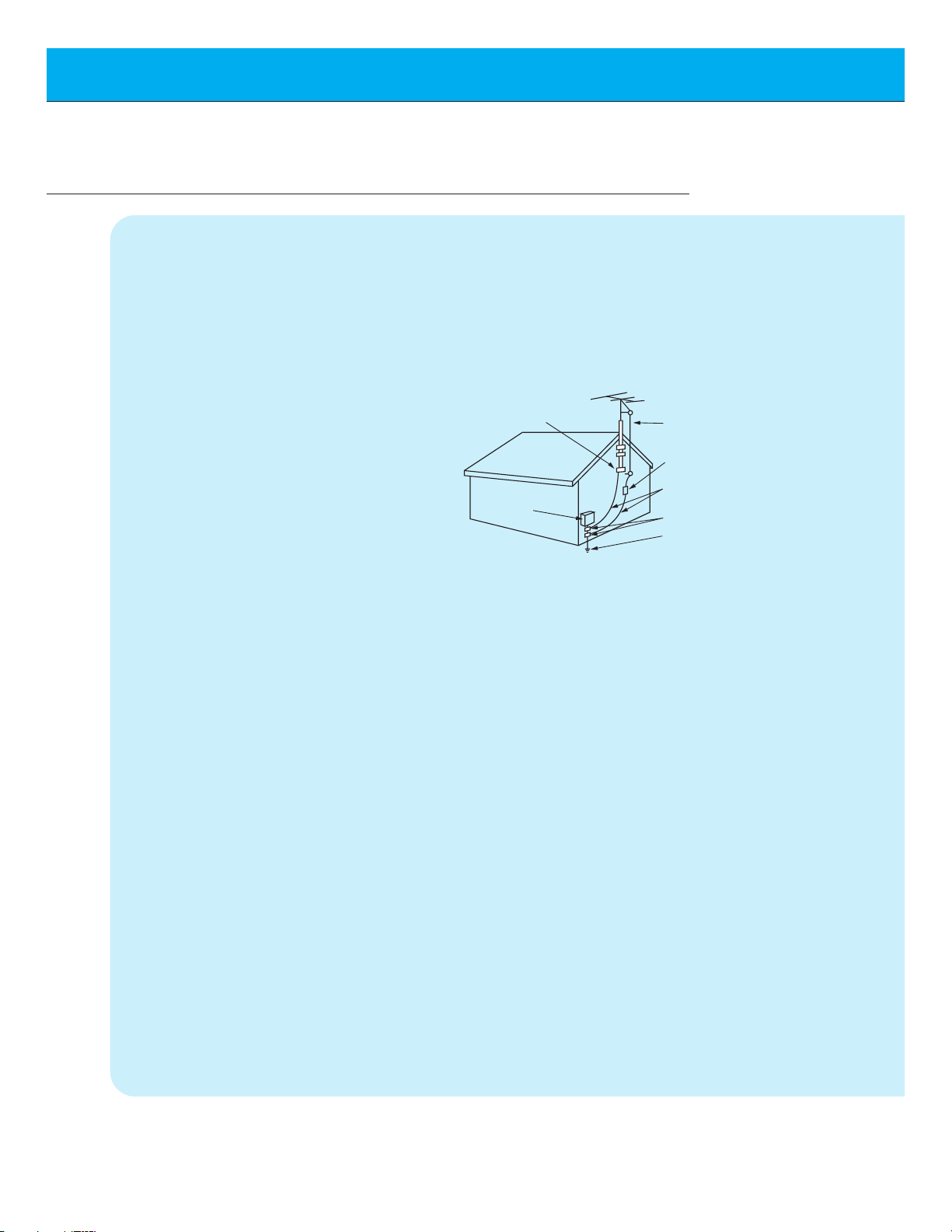
14. Outdoor Antenna Grounding
If an outside antenna or cable system is
connected to the product, be sure the
antenna or cable system is grounded so as
to provide some protection against voltage
surges and built-up static charges. Article
810 of the National Electrical Code (U.S.A.),
ANSI/ NFPA 70 provides information with
regard to proper grounding of the mast and
supporting structure, grounding of the lead-
in wire to an antenna discharge unit, size of
grounding conductors, location of antennadischarge unit, connection to grounding
electrodes, and requirements for the
grounding electrode.
15. Lightning
For added protection for this product
(receiver) during a lightning storm, or when
it is left unattended and unused for long
periods of time, unplug it from the wall outlet
and disconnect the antenna or cable system. This will prevent damage to the product
due to lightning and power-line surges.
16. Power Lines
An outside antenna system should not be
located in the vicinity of overhead power
lines or other electric light or power circuits,
or where it can fall into such power lines or
circuits. When installing an outside antenna
system, extreme care should be taken to
keep from touching such power lines or circuits as contact with them might be fatal.
17. Overloading
Do not overload wall outlets and extension
cords as this can result in a risk of fire or
electric shock.
18. Object and Liquid Entry
Never push objects of any kind into this
(Continued from previous page)
Antenna Lead in Wire
Antenna Discharge Unit
(NEC Section 810-20)
Grounding Conductor
(NEC Section 810-21)
Ground Clamps
Power Service Grounding
Electrode System (NEC
Art 250, Part H)
Ground Clamp
Electric Service
Equipment
Example of Grounding According to National
Electrical Code Instructions
NEC - National Electrical Code
Page 7

7
First step
Overview
Connections
Basic Features
Clock/Timer
Picture & Sound
Special Features
Others
product through openings as they may
touch dangerous voltage points or short-out
parts that could result in a fire or electric
shock. Never spill liquid of any kind on the
product.
19. Servicing
Do not attempt to service this product yourself as opening or removing covers may
expose you to dangerous voltage or other
hazards. Refer all servicing to qualified service personnel.
20. Damage Requiring Service
Unplug this product from the wall outlet and
refer servicing to qualified service personnel
under the following conditions:
a. If the power-supply cord or plug is dam-
aged.
b. If liquid has been spilled, or objects have
fallen into the product.
c. If the product has been exposed to rain
or water.
d. If the product does not operate normally
by following the operating instructions.
Adjust only those controls that are covered by the operating instructions as an
improper adjustment of other controls
may result in damage and will often
require extensive work by a qualified
technician to restore the product to its
normal operation.
e. If the product has been dropped or the
cabinet has been damaged.
f. If the product exhibits a distinct change
in performance.
21. Replacement Parts
When replacement parts are required, be
sure the service technician has used
replacement parts specified by the manufacturer or have the same characteristics as
the original part. Unauthorized substitutions
may result in fire, electric shock, or other
hazards.
22. Safety Check
Upon completion of any service or repairs to
this product, ask the service technician to
perform safety checks to determine that the
product is in proper operating condition.
23. Wall or Ceiling Mounting
The product should be mounted to a wall or
ceiling only as recommended by the manufacturer. The product may slide or fall, causing serious injury to a child or adult, and
serious damage to the product.
24. Heat
The product should be situated away from
heat sources such as radiators, heat registers, stoves, or other products (including
amplifiers) that produce heat.
Page 8
8
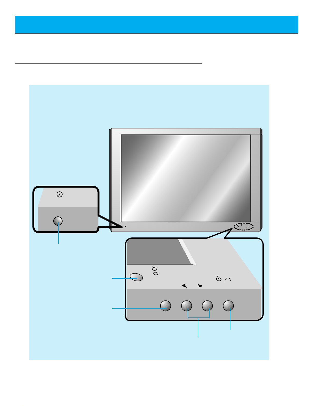
Front Panel Controls
Front Panel Controls
Main power button
INPUT SELECT button
Remote control sensor
Sub power button
VOLUME buttons
ON/OFF
VOLUME
ON/OFF
INPUT
VOLUME
SELECT
INPUT
SELECT
Page 9
9
First step
Overview
Connections
Basic Features
Clock/Timer
Picture & Sound
Special Features
Others
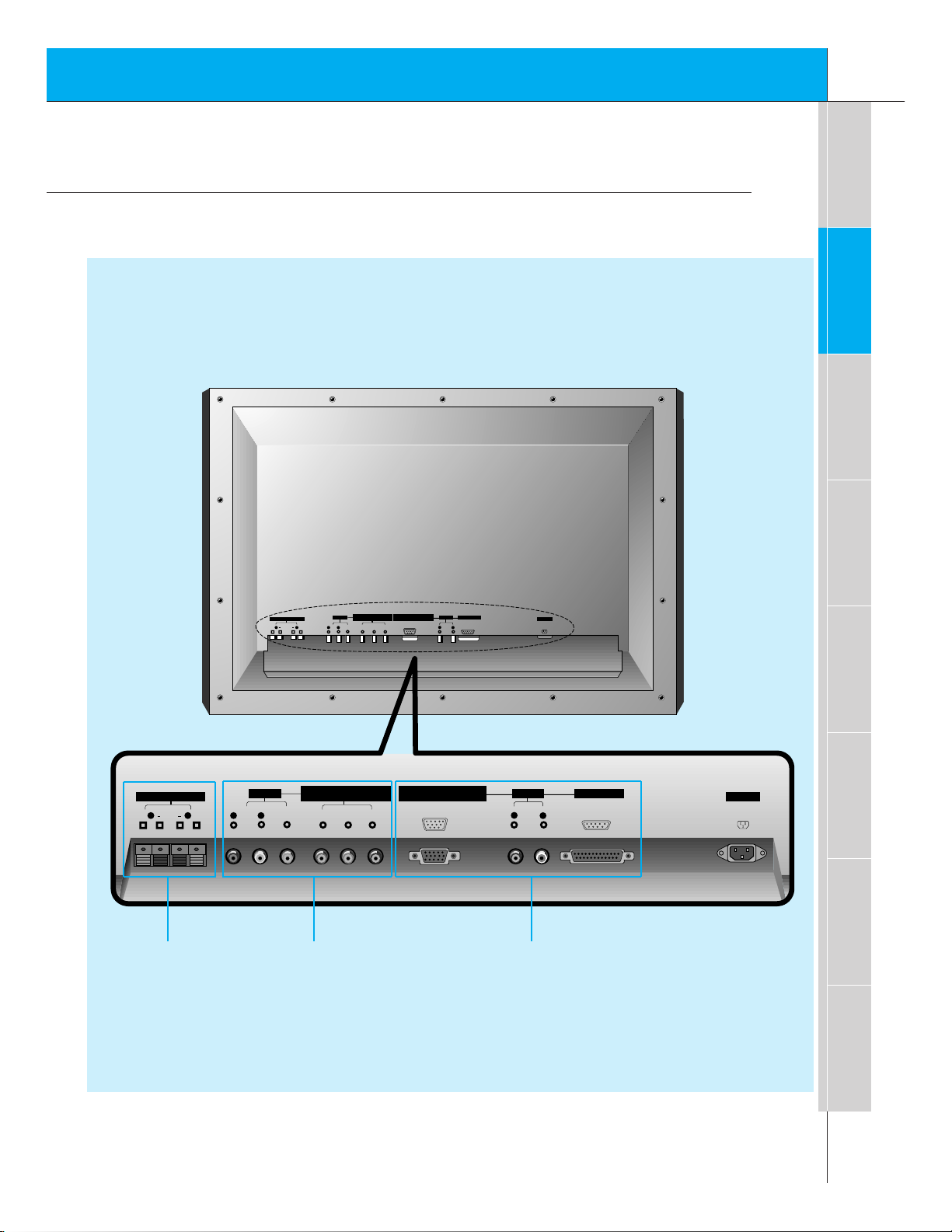
Connection Panel Overview
P
B R
Y P
(+) ( ) (+)( )
AC INPUT
EXTERNAL SPEAKER (8Ω)
AV INPUT
RGB-PC INPUT(VGA/SVGA)
RGB-DTV INPUT(480p/720p/1080i)
R RL L R
AUDIO INPUT RGB INPUT/CONTROL
L
AUDIO
<MONO>
VIDEO
COMPONENT(480i/480p/720p/1080i)
(DVD/DTV INPUT)
PBY
R
P
(+) ( ) (+)( )
AC INPUT
EXTERNAL SPEAKER (8Ω)
AV INPUT
(DVD/DTV INPUT)
COMPONENT(480i/480p/720p/1080i)
RGB-DTV INPUT(480p/720p/1080i)
RGB-PC INPUT(VGA/SVGA)
R
RLL
R
AUDIO INPUT RGB INPUT/CONTROL
L
AUDIO VIDEO
(MONO)
Back Panel
EXTERNAL
SPEAKER (8Ω)
knobs
AV INPUT /
COMPONENT (480i/480p/720p/1080i)
(DVD/DTV INPUT) jacks
RGB-PC INPUT (VGA/SVGA)
RGB-DTV INPUT (480p/720p/1080i) /
AUDIO INPUT /
RGB INPUT/CONTROL jacks/connectors
Page 10
10
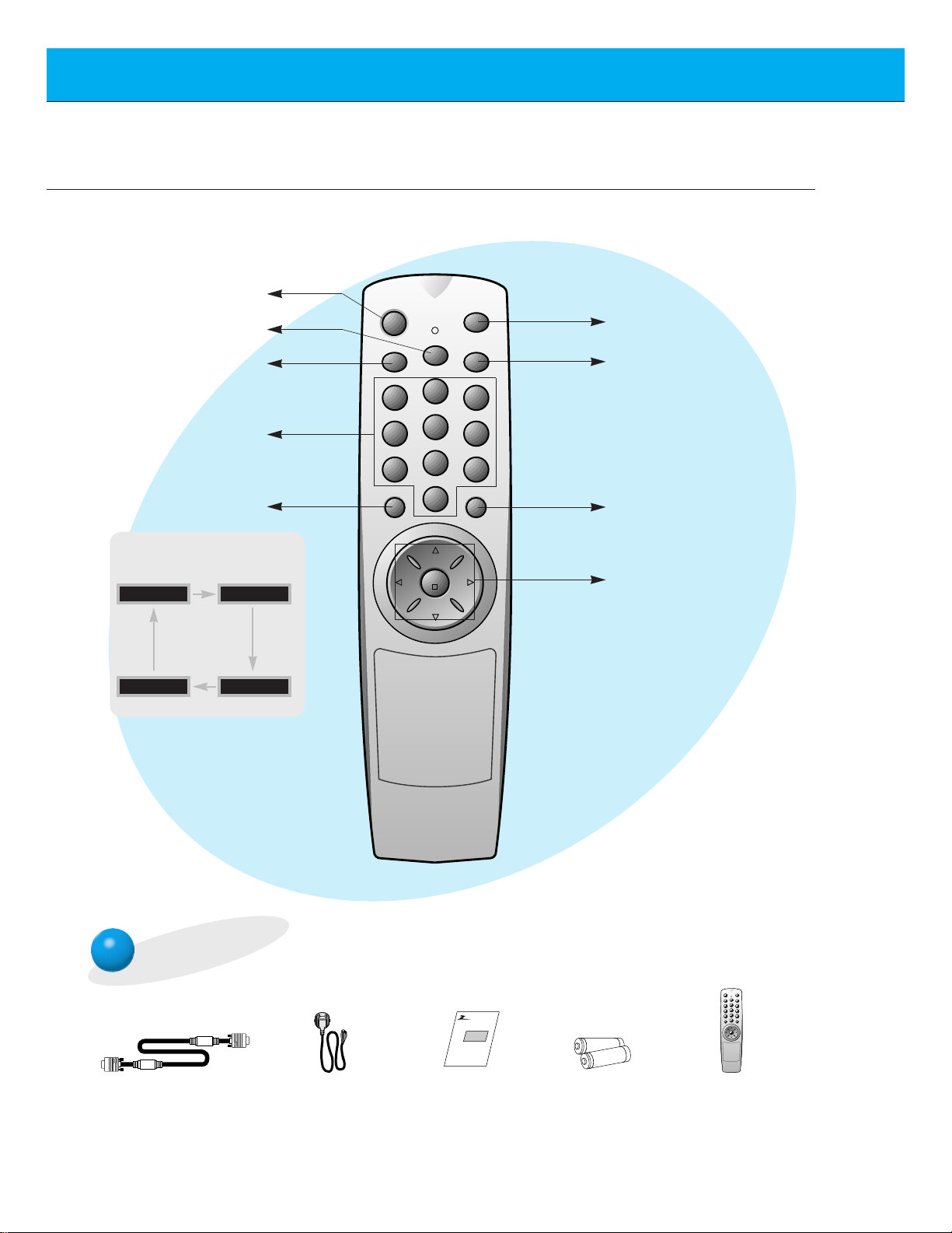
Remote Control Key Functions/Accessories
- When using the remote control aim it at the remote control sensor on the Monitor.
power on
mute
1 3
2
4 6
5
7 9
8
video/pc menu
up
down
vol vol
enter
0
cc
sleep
system off
sleep button
(Refer to p.32)
power on button
mute button
switches the sound on or
off.
video/pc button
number buttons
system off button
menu button
enter button
up/down buttons
vol buttons
cc button
(Refer to p.38~40)
video/pc button on the remote control
Each press of this button changes
the mode as shown below.
VIDEO
RGB-PC
COMPONENT
RGB-DTV
Accessories
D-sub 15 pin cable Power cord
power on
mute
1 3
2
4 6
5
7 9
8
video/pc menu
up
down
vol vol
enter
0
cc
sleep
system off
Remote control
AS mark
Monitor
Owner’s Manual
1.5V
1.5V
Alkaline batteries
Page 11
11
First step
Overview
Connections
Basic Features
Clock/Timer
Picture & Sound
Special Features
Others
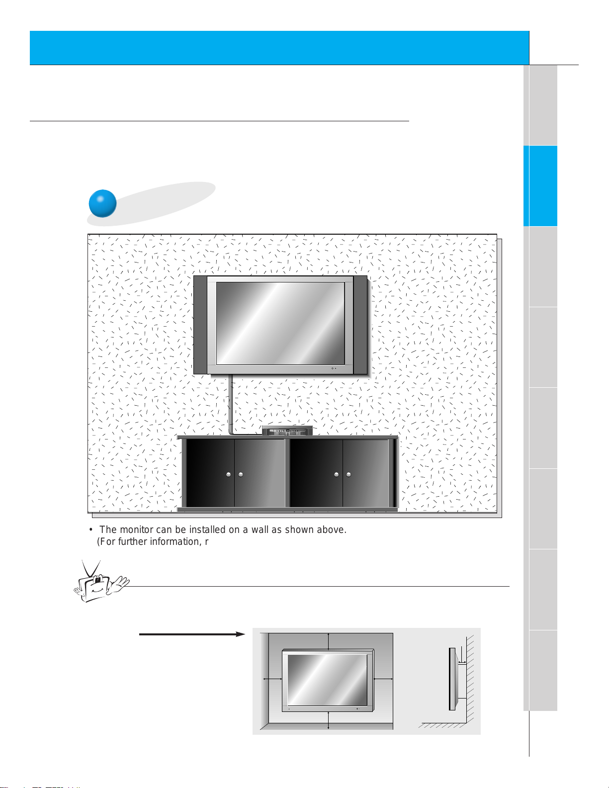
Installation
- Use this product at an altitude lower than 6562 feet (2000m) to get the best
quality picture and sound.
- Your DPDP40V (Monitor) can be installed on a wall as shown below, or on a
desktop pedestal as shown on the next page.
Wall Mount Installation
MULTIMEDIA
ON/OFF
TV/AV MENU ENTER
VOL CH
• The monitor can be installed on a wall as shown above.
(For further information, refer to the optional ‘(Tilt) wall mounting
bracket Installation and Setup Guide’.)
Tips
• To install this monitor safely be sure to provide the necessary clearance for adequate
ventilation as shown below.
a.
(Wall Mount Installation)
4inch
4inch
1.18inch
4inch4inch
Page 12
12
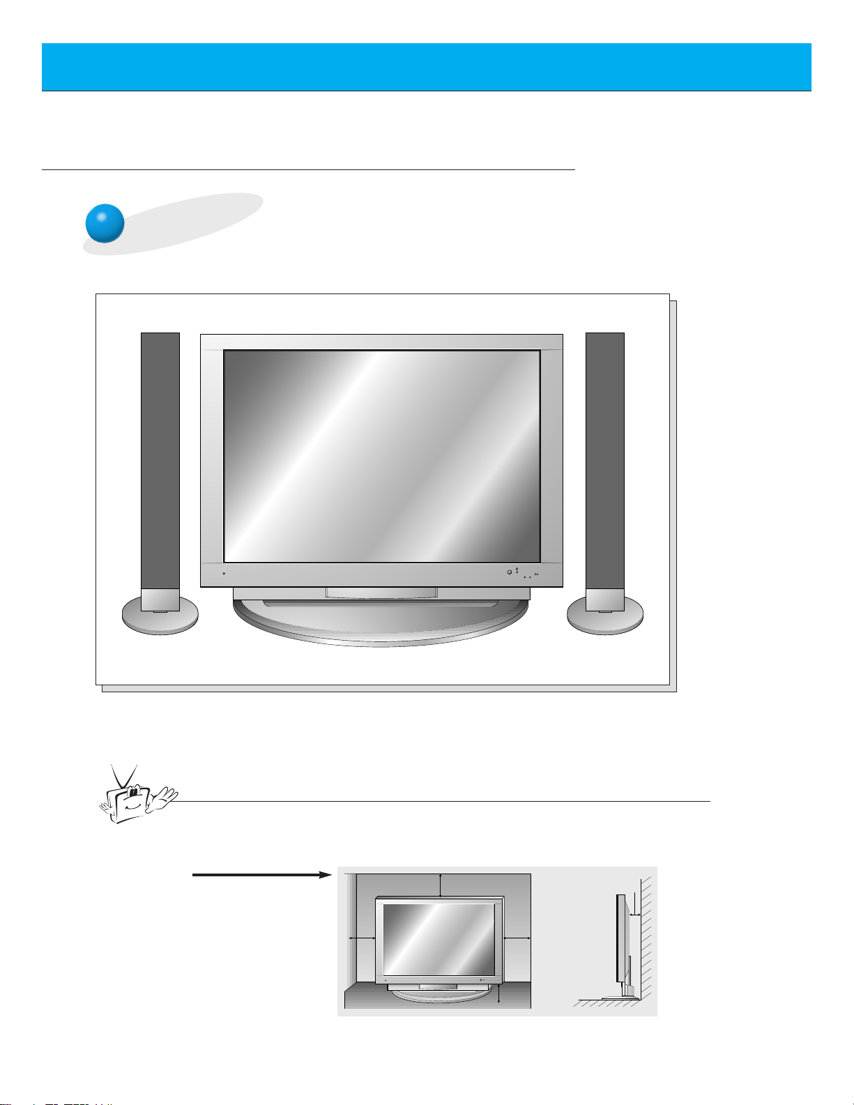
Installation
Desktop Pedestal Installation
ON/OFF
INPUT
VOLUME
SELECT
• The Monitor can be installed on a desk as shown above.
(For further information, refer to the optional ‘Desktop stand Installation and Setup Guide’.)
b.
(Desktop Installation)
Tips
• To install this monitor safely be sure to provide the necessary clearance for adequate
ventilation as shown below.
4inch
4inch
4inch
2.36inch
1.18inch
Page 13

13
First step
Overview
Connections
Basic Features
Clock/Timer
Picture & Sound
Special Features
Others
VCR Setup
- As shown below, when connecting the Monitor to a VCR, match the
colors of AV input jacks on the Monitor with the output jacks on the
VCR: Video = yellow, Audio (Left) = white, Audio (Right) = red.
- If you have a mono VCR, connect the audio cable from the VCR to
the AUDIO (L/MONO) input of the Monitor.
Back panel of the Monitor
To watch the VCR
Press video/pc button on the remote control to select VIDEO.
1
Insert a video tape into the VCR and press
the PLAY button on the VCR.
See VCR owner’s manual.
2
video/pc
Back panel of VCR
Tips
• To prevent picture noise, place the VCR more than 20 inches away from the
Monitor.
RGB-PC INPUT(VGA/SVGA)
COMPONENT(480i/480p/720p/1080i)
AV INPUT
EXTERNAL SPEAKER (8Ω)
<MONO>
R RL L R
AUDIO
VIDEO
(+) ( ) (+)( )
AUDIO INPUT RGB INPUT/CONTROL
(DVD/DTV INPUT)
RGB-DTV INPUT(480p/720p/1080i)
B R
P
Y P
AC INPUT
L
EXTERNAL SPEAKER (8Ω)
R
(+) ( ) (+)( )
S-VIDEO
AV INPUT
AUDIO VIDEO
RLL
OUT
(R) AUDIO (L) VIDEO
IN
COMPONENT(480i/480p/720p/1080i)
(DVD/DTV INPUT)
(MONO)
PBY
RGB-PC INPUT (VGA/SVGA)
RGB-DTV INPUT (480p/720p/1080i)
P
R
AUDIO INPUT RGB INPUT/CONTROL
R
L
Page 14

14
Cable TV Setup
- After subscribing to a cable TV service from a local provider and installing a converter,
you can watch cable TV programming.
To watch cable TV
Press video/pc button on the remote control to select VIDEO.
1
Select cable provided channels using the
cable box.
2
video/pc
Tips
• For further information regarding cable TV, contact your local cable
TV service provider(s).
Back panel of the Monitor
Cable Box
RGB-PC INPUT(VGA/SVGA)
COMPONENT(480i/480p/720p/1080i)
AV INPUT
EXTERNAL SPEAKER (8Ω)
<MONO>
R RL L R
AUDIO
VIDEO
(+) ( ) (+)( )
AUDIO INPUT RGB INPUT/CONTROL
(DVD/DTV INPUT)
RGB-DTV INPUT(480p/720p/1080i)
B R
P
Y P
AC INPUT
L
EXTERNAL SPEAKER (8Ω)
R
(+) ( ) (+)( )
AV INPUT
AUDIO VIDEO
RLL
COMPONENT(480i/480p/720p/1080i)
(DVD/DTV INPUT)
(MONO)
(R) AUDIO (L) VIDEO
TV
VCR
PBY
RGB-PC INPUT (VGA/SVGA)
RGB-DTV INPUT (480p/720p/1080i)
P
R
RF Cable
AUDIO INPUT RGB INPUT/CONTROL
R
L
Page 15

15
First step
Overview
Connections
Basic Features
Clock/Timer
Picture & Sound
Special Features
Others
To watch external AV source
Press video/pc button on the remote control to select VIDEO.
1
Operate the corresponding external equipment. See external equipment operating
guide.
2
video/pc
External AV Source Setup
- As shown below, when connecting the Monitor to an external source, match the colors of AV
input jacks on the Monitor with the output jacks on the audio/video equipment:
Video = yellow, Audio (Left) = white, Audio (Right) = red.
RGB-PC INPUT(VGA/SVGA)
COMPONENT(480i/480p/720p/1080i)
AV INPUT
EXTERNAL SPEAKER (8Ω)
<MONO>
R RL L R
AUDIO
VIDEO
(+) ( ) (+)( )
AUDIO INPUT RGB INPUT/CONTROL
(DVD/DTV INPUT)
RGB-DTV INPUT(480p/720p/1080i)
B R
P
Y P
AC INPUT
L
EXTERNAL SPEAKER
(+) ( ) (+)( )
(8Ω)
R
AV INPUT
AUDIO VIDEO
(MONO)
RLL
COMPONENT(480i/480p/720p/1080i)
(DVD/DTV INPUT)
PBY
P
R
RGB-PC INPUT (VGA/SVGA)
RGB-DTV INPUT (480p/720p/1080i)
AUDIO VIDEO
R L
AUDIO INPUT RGB INPUT/CONTROL
R
L
Camcorder
Video game set
DDR
Page 16

16
DVD Setup
• DVD input is set at 480i/480p mode.
• Connect DVD video inputs to Y, PB, PR of COMPONENT (480i/480p/720p/1080i)
(DVD/DTV INPUT) and audio inputs to Audio jacks of AV INPUT.
How to connect a DVD (digital video disk player)
How to use
• Turn on the DVD player, and insert a DVD.
• Press video/pc button on the Monitor remote control to
select COMPONENT. Use DVD to play DVD, see DVD
owner’s manual.
• Component Input ports
Connect DVD player jacks to Monitor
Component input jacks as indicated below.
Back panel of a DVD player
Component input jacks on
the Monitor
Y
PB
PR
Video output jacks
on the DVD player
Y
Y
Y
Y
Pb
PB
B-Y
Cb
Pr
PR
R-Y
Cr
Back panel of the Monitor
RGB-PC INPUT(VGA/SVGA)
COMPONENT(480i/480p/720p/1080i)
AV INPUT
EXTERNAL SPEAKER (8Ω)
<MONO>
R RL L R
AUDIO
VIDEO
(+) ( ) (+)( )
AUDIO INPUT RGB INPUT/CONTROL
(DVD/DTV INPUT)
RGB-DTV INPUT(480p/720p/1080i)
B R
P
Y P
AC INPUT
L
EXTERNAL SPEAKER (8Ω)
R
(+) ( ) (+)( )
(R) AUDIO (L)
AV INPUT
AUDIO VIDEO
(MONO)
RLL
COMPONENT(480i/480p/720p/1080i)
(DVD/DTV INPUT)
PBY
P
R
RGB-PC INPUT (VGA/SVGA)
RGB-DTV INPUT (480p/720p/1080i)
AUDIO INPUT RGB INPUT/CONTROL
R
L
Page 17

17
First step
Overview
Connections
Basic Features
Clock/Timer
Picture & Sound
Special Features
Others
DTV Setup
- To watch digitally broadcast programs, purchase/connect a digital SET-TOP BOX.
How to connect a user-supplied Digital Set-top Box
How to use
• Turn on the digital SET-TOP BOX.
(Refer to the owner’s manual for the digital SET-TOP BOX.)
• Press video/pc button on the remote control to select COMPONENT or RGB-DTV.
Back panel of a digital SET-TOP BOX
or
• Connect DTV set-top box video output to Monitor Y, PB, PR COMPONENT
(480i/480p/720p/1080i) DVD/DTV INPUT or to the Monitor RGB-PC INPUT (VGA/SVGA)
RGB-DTV INPUT (480p/720p/1080i) connector.
• Connect DTV set-top box audio outputs to Monitor AV INPUT Audio jacks.
Back panel of the Monitor
RGB-PC INPUT(VGA/SVGA)
COMPONENT(480i/480p/720p/1080i)
AV INPUT
EXTERNAL SPEAKER (8Ω)
<MONO>
R RL L R
AUDIO
VIDEO
(+) ( ) (+)( )
AUDIO INPUT RGB INPUT/CONTROL
(DVD/DTV INPUT)
RGB-DTV INPUT(480p/720p/1080i)
B R
P
Y P
AC INPUT
L
EXTERNAL SPEAKER (8Ω)
R
(+) ( ) (+)( )
AV INPUT
AUDIO VIDEO
(MONO)
RLL
COMPONENT(480i/480p/720p/1080i)
(DVD/DTV INPUT)
PBY
RGB-PC INPUT (VGA/SVGA)
RGB-DTV INPUT (480p/720p/1080i)
P
R
AUDIO INPUT RGB INPUT/CONTROL
R
L
(R) AUDIO (L) (R) AUDIO (L) DTV OUTPUT
Page 18

18
PC Computer Setup
- See your computer ’s image on the Monitor.
• Press POWER button on the PC and press ON/OFF button on the Monitor. After this press button
on the Monitor or press POWER button on the remote control.
• Press video/pc button on the remote control to select RGB-PC.
• Set the resolution of PC under SVGA (800x600). (See page 19.)
How to connect
How to use
Make the connections shown in the illustration below
• Set the computer video output to VGA or SVGA; for the best picture quality. (If the video output of the PC is
not compatible with the Monitor, no picture will appear on the Monitor. See page 19.)
• As shown below, connect the video output of the PC to the Monitor RGB-PC INPUT (VGA/SVGA) RGB-DTV
INPUT (480p/720p/1080i).
• Connect the audio out from the PC to the Audio jacks on the Monitor. (Audio cables are not included with the
Monitor)
• If available, adjust PC sound to your preference.
• To avoid burning an image onto the Monitor screen, don’t have a still picture on the
screen for a long period time.
Back panel of the Monitor
RGB-PC INPUT(VGA/SVGA)
COMPONENT(480i/480p/720p/1080i)
AV INPUT
EXTERNAL SPEAKER (8Ω)
<MONO>
R RL L R
AUDIO
VIDEO
(+) ( ) (+)( )
AUDIO INPUT RGB INPUT/CONTROL
(DVD/DTV INPUT)
RGB-DTV INPUT(480p/720p/1080i)
B R
P
Y P
AC INPUT
L
EXTERNAL SPEAKER (8Ω)
R
(+) ( ) (+)( )
AV INPUT
AUDIO VIDEO
(MONO)
RLL
COMPONENT(480i/480p/720p/1080i)
(DVD/DTV INPUT)
PBY
RGB-PC INPUT (VGA/SVGA)
RGB-DTV INPUT (480p/720p/1080i)
P
R
AUDIO INPUT RGB INPUT/CONTROL
R
L
Tips
Page 19

19
First step
Overview
Connections
Basic Features
Clock/Timer
Picture & Sound
Special Features
Others
Monitor Image Display Specifications
640x400 37.861 85.08
720x400 31.469 70.08
31.469 59.94
35.000 66.66
37.861 72.80
37.500 75.00
43.269 85.00
45.913 90.03
53.011 100.04
64.062 120.00
35.156 56.25
37.879 60.31
48.077 72.18
46.875 75.00
53.674 85.06
49.725832x624 74.55
Resolution
Horizontal
Frequency (KHz)
Vertical
Frequency (Hz)
640x480
(VGA)
800x600
(SVGA)
Page 20

20
3
2
PC Computer Mode Feature Check
- Select RGB-PC first, see page 10.
1
Press the menu button to show menus onscreen.
Use up/down or vol button to select the feature you
want to use.
• Press the enter button to remove menus.
Press the up/down button to select menus.
• Each press will cycle through the different menus as shown below.
menu
up
down
up
down
vol vol
APC
G
USER CONTROL
G
MOVE GNEXT AEXIT
PICTURE
D
E
DASP
G
USER CONTROL
G
MOVE GNEXT AEXIT
SOUND
D
E
LANGUAGE
G
CAPTION / TEXT
G
CAPTIONS
G
AUTO OFF
G
SCREEN
G
MOVE GNEXT AEXIT
SPECIAL
D
E
CLOCK
G
OFF-TIMER
G
ON-TIMER
G
MOVE GNEXT AEXIT
TIMER
D
E
Picture menu Sound menu
Special menu Timer menu
Page 21

21
First step
Overview
Connections
Basic Features
Clock/Timer
Picture & Sound
Special Features
Others
1
3
PC Computer Mode Adjustments
Press the up/down button to select SCREEN
and then press the vol ( G) button.
If picture needs to be adjusted more after auto adjustment, adjust
H-POSITION, V-POSITION and PHASE. See the following pages.
Auto adjustment
Press the menu button and then press the up/down button
to select SPECIAL menu.
Press the vol ( G) button.
menu
up
down
vol
LANGUAGE
G
CAPTION
G
AUTO OFF
G
SCREEN
G
RGB-OUTPUT
G
SPECIAL
2
Press the up/down button to select
AUTO.CONFIG. and then press the
vol ( G) button.
• Position and trembling of picture are automatically adjusted.
LANGUAGE
G
CAPTION / TEXT
G
CAPTIONS
G
AUTO OFF
G
SCREEN
G
TO SET DATA
LANGUAGE
G
CAPTION
G
AUTO OFF
G
SCREEN
G
RGB-OUTPUT
G
AUTO.CONFIG.
G
ARC
G
H-POSITION
G
V-POSITION
G
PHASE
G
RESET
G
TO SET
SCREEN
G
AUTO.CONFIG.
G
READY
up
down
vol
down
up
vol
Page 22

22
3
2
1
PC Computer Mode Adjustments
Press the up/down button to select SCREEN
and then press the vol ( G) button.
Adjusting horizontal / vertical position
Press the up/down button to select
H-POSITION or V-POSITION and then press
the vol ( G) button.
• The adjustment range of H-POSITION and
V-POSITION is -32 ~ +32.
Press the vol button to adjust until you get desired horizontal or
vertical position and then press the enter button to remove menus.
Press the menu button and then press the up/down button
to select
SPECIAL menu.
Press the vol ( G) button.
LANGUAGE
G
CAPTION
G
AUTO OFF
G
SCREEN
G
RGB-OUTPUT
G
SPECIAL
LANGUAGE
G
CAPTION / TEXT
G
CAPTIONS
G
AUTO OFF
G
SCREEN
G
TO SET DATA
LANGUAGE
G
CAPTION
G
AUTO OFF
G
SCREEN
G
RGB-OUTPUT
G
AUTO.CONFIG.
G
ARC
G
H-POSITION
G
V-POSITION
G
PHASE
G
RESET
G
0
SCREEN
G
H-POSITION
G
READY
menu
up
down
up
down
vol
vol
up
vol
down
vol vol
enter
Page 23

23
First step
Overview
Connections
Basic Features
Clock/Timer
Picture & Sound
Special Features
Others
3
2
1
Use the up/down button to select SCREEN
and then press the vol ( G) button.
Picture Phase Adjustments
• If the picture isn’t clear after auto adjustment and especially if the characters are still trembling, then
adjust the picture phase manually.
Initializing
• To initialize the adjusted value, select RESET with the up/down button and
then press the vol (G) button.
Use the up/down button to select PHASE
and then press the vol ( G) button.
• The adjustment range of PHASE is 0 ~ 31.
Press the vol button to adjust phase and then press the enter button.
LANGUAGE
G
CAPTION
G
AUTO OFF
G
SCREEN
G
RGB-OUTPUT
G
SPECIAL
LANGUAGE
G
CAPTION / TEXT
G
CAPTIONS
G
AUTO OFF
G
SCREEN
G
TO SET DATA
LANGUAGE
G
CAPTION
G
AUTO OFF
G
SCREEN
G
RGB-OUTPUT
G
AUTO.CONFIG.
G
ARC
G
H-POSITION
G
V-POSITION
G
PHASE
G
RESET
G
27
up
down
vol
Press the menu button and then press the up/down button
to select SPECIAL menu.
Press the vol ( G) button.
SCREEN
G
PHASE
G
READY
menu
up
down
vol
down
up
vol
vol vol
enter
Page 24

24
Using The Remote Control
Installing batteries
• Open the battery compartment cover on the back
of the remote control and insert the batteries with
correct polarity, match “+” with “+”, and match “-”
with “-”.
• Install two 1.5V “AA” alkaline batteries.
Don’t mix the used batteries with new batteries.
Notes for using the remote control
Make sure these are no
objects between the
remote control and its
sensor on the monitor.
Don’t place the remote control near a
heater or in a damp place. Astrong
impact on the remote control may
damage it so that it may not work.
The IR signal from the remote
control can be affected by sun
light or other strong light. In this
case, darken the room or
remove the strong light.
Page 25

25
First step
Overview
Connections
Basic Features
Clock/Timer
Picture & Sound
Special Features
Others
Turning on the Monitor
3
2
1
2
1
- When using the remote control, aim it at its sensor on the Monitor front panel.
Turning on the Monitor after installation and connection
Turning on the Monitor
Connect power cord correctly.
Press the ON/OFF button on the Monitor. At this moment, the Monitor is
switched to standby mode. Press the button on the Monitor or press the
power on button on the remote control and then the Monitor will be turned on.
• Press the button on the Monitor or press the power on button on the
remote control to turn on the Monitor.
If the Monitor was turned off with the button on the Monitor
• Press the ON/OFF button on the Monitor to turn on the Monitor.
If the Monitor was turned off with the ON/OFF button on the Monitor
• Press the ON/OFF button on the Monitor and then press the button on
the Monitor or press the power on button on the remote control to turn on
the Monitor.
If the Monitor was turned off with the system off button on the remote
control and also the ON/OFF button on the Monitor
Tips
• Adjusting volume level
The Vol (GG) button makes the sound louder and the Vol (FF) button quiets the
sound.
Page 26

26
Selecting language for the menus
3
2
1
Press the up/down button to select
LANGUAGE and then press the vol
( G) button.
Press the up/down button to select
the desired language.
Press the enter button.
enter
Press the menu button and then press the up/down button to
select SPECIAL menu.
Press the vol ( G) button.
up
down
vol
LANGUAGE
G
CAPTION
G
AUTO OFF
G
SCREEN
G
RGB-OUTPUT
G
SPECIAL
LANGUAGE
G
CAPTION / TEXT
G
CAPTIONS
G
AUTO OFF
G
SCREEN
G
ENGLISH
ESPAÑOL
FRANÇAIS
LANGUAGE
G
LANGUAGE
G
CAPTION
G
AUTO OFF
G
SCREEN
G
RGB-OUTPUT
G
SPECIAL
LANGUAGE
G
CAPTION / TEXT
G
CAPTIONS
G
AUTO OFF
G
SCREEN
G
ENGLISH
ESPAÑOL
FRANÇAIS
ENGLISH
READY
menu
up
vol
down
up
down
Page 27

1
3
2
27
First step
Overview
Connections
Basic features
Clock/Timer
Picture & Sound
Special Features
Others
Press the menu button.
Press the up/down button.
• Each press will cycle through the menus shown below.
menu
Checking features
Press the up/down or vol button to select a
feature you want to use.
• Press the enter button to remove menus.
up
down
up
down
vol vol
APC
G
USER CONTROL
G
MOVE GNEXT AEXIT
PICTURE
D
E
DASP
G
USER CONTROL
G
MOVE GNEXT AEXIT
SOUND
D
E
LANGUAGE
G
CAPTION / TEXT
G
CAPTIONS
G
AUTO OFF
G
SCREEN
G
MOVE GNEXT AEXIT
SPECIAL
D
E
CLOCK
G
OFF-TIMER
G
ON-TIMER
G
MOVE GNEXT AEXIT
TIMER
D
E
Picture menu Sound menu
Special menu Timer menu
Page 28

28
Setting current time
2
1
Press the up/down button to select
CLOCK and then press the vol (
G
)
button.
Setting hour
(If current time is 10:30 in the morning)
Press the up/down button to
select AM 10 and then press the
vol ( G) button.
Press the MENU button and then press the up/down button
to select
TIMER menu.
Press the vol ( G) button.
LANGUAGE
G
CAPTION
G
AUTO OFF
G
SCREEN
G
RGB-OUTPUT
G
TIMER
CLOCK
G
OFF-TIMER
G
ON-TIMER
G
- - : - - AM
CLOCK
G
LANGUAGE
G
CAPTION
G
AUTO OFF
G
SCREEN
G
RGB-OUTPUT
G
TIMER
CLOCK
G
OFF-TIMER
G
ON-TIMER
G
- - : 00 AM
10 AM
READY
menu
up
vol
down
up
down
vol
up
vol
down
Page 29

29
First step
Overview
Connections
Basic Features
Clock/Timer
Picture & Sound
Special Features
Others
4
3
Setting minute
Press the up/down button to
select 30 and then press the
enter button.
Removing Menu
Press the enter button again and the screen
display disappears.
enter
LANGUAGE
G
CAPTION
G
AUTO OFF
G
SCREEN
G
RGB-OUTPUT
G
TIMER
CLOCK
G
OFF-TIMER
G
ON-TIMER
G
10 : 30 AM
30
up
enter
down
Page 30

30
1
Press the up/down button to select ON-
TIMER and then press the vol (
G
) button.
(Turning on at 7:30 AM with volume 40)
Press the up/down button to select OFF-TIMER and
then press the vol (
G
) button.
(Turning off at 11:30 PM)
Off Timer
Tips
• On/Off-Timer function can be operated only if current time has been already set.
• If On-Timer feature is active, the current channel will change to the set channel
when the On-Timer setting is reached.
• ‘SLEEP 1’ is displayed, one minute before the Monitor is due to switch off.
Press the menu button and then press the up/down button to
select TIMER menu.
Press the vol ( G) button.
LANGUAGE
G
CAPTION
G
AUTO OFF
G
SCREEN
G
RGB-OUTPUT
G
TIMER
CLOCK
G
OFF-TIMER
G
ON-TIMER
G
- - : - - AM
30
HOLD
ON-TIMER
G
Setting On / Off-Timer
menu
up
down
vol
READY
up
vol
down
Page 31

31
First step
Overview
Connections
Basic Features
Clock/Timer
Picture & Sound
Special Features
Others
4
3
2
Press the up/down button to select PM 11 and then
press the vol ( G) button.
Setting hour
Press the up/down button to select AM 7
and then press the vol ( G) button.
Off Timer
Setting minute
Press the up/down button to select 30
and then press the vol ( G) button.
Press the up/down button to select
30 and then press the enter
button to complete the setting.
Setting volume
Press the up/down button to select 40
and then press the enter button to complete the setting.
• Unless a button is pressed within two hours after turning on the Monitor with the On-Timer
feature, the Monitor automatically turns off.
To cancel On/Off-Timer function
Press the vol button to select RUN in step 1 on p.30 and then press
the up/down button to select HOLD.
Press the enter button to complete the setting.
Off Timer
LANGUAGE
G
CAPTION
G
AUTO OFF
G
SCREEN
G
RGB-OUTPUT
G
TIMER
CLOCK
G
OFF-TIMER
G
ON-TIMER
G
- - : 00 AM
30
RUN
AM07
LANGUAGE
G
CAPTION
G
AUTO OFF
G
SCREEN
G
RGB-OUTPUT
G
TIMER
CLOCK
G
OFF-TIMER
G
ON-TIMER
G
07 : 00 AM
30
RUN
30
LANGUAGE
G
CAPTION
G
AUTO OFF
G
SCREEN
G
RGB-OUTPUT
G
TIMER
CLOCK
G
OFF-TIMER
G
ON-TIMER
G
07 : 30 AM
40
RUN
40
up
vol
down
up
vol
down
up
enter
down
Page 32

32
Setting sleep time
This feature automatically turns the Monitor off after a preset time.
Press the sleep button to set sleep time.
Each time you press the next preset setting
time is changed as shown below.
• To release sleep time setting, press sleep or vol
button repeatedly to select --- F G.
• ‘SLEEP 1’ is displayed, one minute before the
Monitor is due to switch off.
sleep
--- F G 10 F G
20 F G 30 F G
120 F G180 F G
240 F G
90 F G 60 F G
• When the sleep time you want is displayed on the screen, don’t press the
sleep button. The screen display disappears and sleep time is set.
• To check remaining sleep time after setting, press the sleep or enter button
just once.
• If you turn the Monitor off after setting the sleep timer, the setting will be
erased. The sleep timer will then have to be set again.
30
F G
SLEEP
z
z
Tips
Page 33

33
First step
Overview
Connections
Basic Features
Clock/Timer
Picture & Sound
Special Features
Others
Auto picture control
APC sets the Monitor with the best picture appearance
2
1
Press the up/down button to select
APC and then press the vol (
G
)
button.
Press the up/down button to select
the desired picture appearance and
then press the enter button.
Press the menu button and then press the up/down button to
select
PICTURE menu.
Press the vol ( G) button.
up
down
vol
LANGUAGE
G
CAPTION
G
AUTO OFF
G
SCREEN
G
RGB-OUTPUT
G
PICTURE
APC
G
USER CONTROL
G
CLEAR
SOFT
USER
APC
G
LANGUAGE
G
CAPTION
G
AUTO OFF
G
SCREEN
G
RGB-OUTPUT
G
PICTURE
APC
G
USER CONTROL
G
CLEAR
SOFT
USER
CLEAR
• If a still picture is on the screen for more than 5 minutes, the screen darkens.
If any function is activated, the brightness of the screen is restored.
READY
menu
down
up
vol
up
enter
down
Tips
Page 34

34
Auto programming CH 13
7%
3
2
1
Press the up/down button to select
USER CONTROL and then press the
vol ( G) button.
Press the up/down button to select
CONTRAST and then press the vol
( G) button. (if adjusting contrast)
Press the vol button to make appropriate
adjustment and then press the enter button.
• Press the up/down button to select other items.
Press the menu button and then press the up/down button to
select PICTURE menu.
Press the vol ( G) button.
LANGUAGE
G
CAPTION
G
AUTO OFF
G
SCREEN
G
RGB-OUTPUT
G
PICTURE
APC
G
USER CONTROLGCONTRAST
G
BRIGHTNESS
G
COLOR
G
TINT
G
SHARPNESS
G
USER CONTROL
G
LANGUAGE
G
CAPTION
G
AUTO OFF
G
SCREEN
G
RGB-OUTPUT
G
PICTURE
APC
G
USER CONTROLGCONTRAST
G
BRIGHTNESS
G
COLOR
G
TINT
G
SHARPNESS
G
CONTRAST
G
CONTRAST 35
MOVE F GADJUST ABACK
D
E
Adjusting picture appearance
menu
up
down
vol
READY
up
vol
down
up
vol
down
vol vol
enter
Page 35

35
First step
Overview
Connections
Basic Features
Clock/Timer
Picture & Sound
Special Features
Others
Auto sound control
3
2
1
Press the up/down button to select
DASP and then press the vol (
G
)
button.
If you wish to change the characteristics of the sound options, press the
up/down buttons to select the desired
sound option.
Press the enter button to set sound type and remove menu.
enter
Press the menu button and then press the up/down button to
select SOUND menu.
Press the vol ( G) button.
up
down
vol
LANGUAGE
G
CAPTION
G
AUTO OFF
G
SCREEN
G
RGB-OUTPUT
G
SOUND
DASP
G
USER CONTROL
G
NEWS
CINEMA
MUSIC
SPORTS
USER
DASP
G
LANGUAGE
G
CAPTION
G
AUTO OFF
G
SCREEN
G
RGB-OUTPUT
G
SOUND
DASP
G
USER CONTROL
G
NEWS
CINEMA
MUSIC
SPORTS
USER
USER
• Because the Monitor automatically adjusts the sound so that it is appropriate for the program content, you can enjoy the best sound without any special adjustments with the DASP.(Digital Audio
Signal Processing) feature.
READY
menu
down
up
vol
up
down
Page 36

36
Adjusting sound
2
1
Use the up/down button to select USER
CONTROL
and then press the vol ( G)
button.
Use the up/down button to select your
desired sound option and then press
the vol (
G
) button.
3
Use the vol button to make appropriate adjustment and then
press the enter button to remove menu.
Press the menu button and then use the up/down button to
select
SOUND menu.
Press the vol ( G) button.
LANGUAGE
G
CAPTION
G
AUTO OFF
G
SCREEN
G
RGB-OUTPUT
G
SOUND
DASP
G
USER CONTROLGBALANCE
G
TREBLE
G
BASS
G
USER CONTROL
G
LANGUAGE
G
CAPTION
G
AUTO OFF
G
SCREEN
G
RGB-OUTPUT
G
SOUND
DASP
G
USER CONTROLGBALANCE
G
TREBLE
G
BASS
G
BALANCE
G
READY
menu
up
vol
down
up
vol
down
up
down
vol
vol vol
enter
Page 37

37
First step
Overview
Connections
Basic Features
Clock/Timer
Picture & Sound
Special Features
Others
Auto off setup
• Auto off turns the Monitor turn off automatically approximately ten minutes after no signal is
received.
Press the menu button and then use the up/down button to
select SPECIAL menu.
Press the vol ( G) button.
2
1
Use the up/down button to select AUTO
OFF
and then press the vol ( G) button.
Use the up/down button to select
ON or OFF and then press the enter
button to remove menu.
LANGUAGE
G
CAPTION
G
AUTO OFF
G
SCREEN
G
RGB-OUTPUT
G
SPECIAL
LANGUAGE
G
CAPTION / TEXT
G
CAPTIONS
G
AUTO OFF
G
SCREEN
G
ON
OFF
AUTO OFF
G
LANGUAGE
G
CAPTION
G
AUTO OFF
G
SCREEN
G
RGB-OUTPUT
G
SPECIAL
LANGUAGE
G
CAPTION / TEXT
G
CAPTIONS
G
AUTO OFF
G
SCREEN
G
ON
OFF
OFF
READY
menu
up
down
down
up
vol
vol
up
enter
down
Page 38

38
Closed caption / Text setup
- Closed captioning is a process which converts the audio portion of a television program
into written words which then appear on the television screen in a form similar to subtitles.
Closed captions allow viewers to read the dialogue and narration of television programs.
- Captions are the subtitles of the dialogue and narration of
television programs. For prerecorded programs, program
dialogue can be arranged into captions in advance. It’s possible to caption a live program by using a process called
“real-time captioning”, which creates captions instantly.
Real-time captioning is normally done by professional
reporters using a machine shorthand system and computer
for translation into English.
Captioning is an effective system for the hearing-impaired,
and it can also aid in teaching language skills.
• The picture at left shows a typical caption.
Using Closed Captions
FOLLOW ME
• Not all TV broadcasts include closed caption signals.
• Sometimes TV stations broadcast four different caption signals on the same channel.
By selecting from cc 1 to cc 4, you can choose which signal you view. cc 1 is usually
the signal with the captions, while another mode might show demonstration or programming information.
• Your monitor might not receive caption signals normally in the following situations.
Poor reception conditions are encountered:
IGNITION:
Picture may flutter, drift, suffer from black spots or horizontal streaking. Usually caused by
interference from automobile ignition systems, neon lamps, electrical drills and other electrical appliances.
GHOSTS:
Ghosts are caused when the Plasma Display signal splits and follows two paths. One is the
direct path and the other is reflected off tall buildings, hills or other objects. Changing the
direction or position of the antenna may improve reception.
SNOW:
If your receiver is located at the weak, fringe area of a TV signal, your picture may be marred
by small dots. It may be necessary to install a special antenna to improve the picture.
An old, bad or illegally recorded tape is played.
Strong, random signals from a car or airplane interfere with the Plasma Display signal.
The signal from the antenna is weak.
The program wasn’t captioned when it was produced, transmitted or taped.
Tips
Page 39

39
First step
Overview
Connections
Basic Features
Clock/Timer
Picture & Sound
Special Features
Others
Operating Closed Caption / Text
Press the menu button and then use the up/down button to
select SPECIAL menu.
Press the vol ( G) button.
menu
up
down
vol
2
1
Use the up/down button to select
CAPTION / TEXT and then press the
vol ( G) button.
Use the up/down button to select a
caption/text option and then press
the enter button.
LANGUAGE
G
CAPTION
G
AUTO OFF
G
SCREEN
G
RGB-OUTPUT
G
SPECIAL
LANGUAGE
G
CAPTION / TEXT
G
CAPTIONS
G
AUTO OFF
G
SCREEN
G
CC 1
CC 2
CC 3
CC 4
TEXT 1
TEXT 2
TEXT 3
TEXT 4
CAPTION / TEXT
G
LANGUAGE
G
CAPTION
G
AUTO OFF
G
SCREEN
G
RGB-OUTPUT
G
SPECIAL
LANGUAGE
G
CAPTION / TEXT
G
CAPTIONS
G
AUTO OFF
G
SCREEN
G
CC 1
CC 2
CC 3
CC 4
TEXT 1
TEXT 2
TEXT 3
TEXT 4
CC 1
READY
up
vol
down
up
enter
down
Page 40

40
Closed caption / Text continued
4
3
Use the up/down button to select
CAPTIONS and then press the vol (
G
)
button.
Use the up/down button to select
ON or OFF and then press the enter
button.
• To release this function, select OFF.
• If you select EZ MUTE, captions or text appear when the sound is muted.
• You can turn the caption/text option OFF, ON or EZ MUTE directly using the cc button on the remote control.
LANGUAGE
G
CAPTION
G
AUTO OFF
G
SCREEN
G
RGB-OUTPUT
G
SPECIAL
LANGUAGE
G
CAPTION / TEXT
G
CAPTIONS
G
AUTO OFF
G
SCREEN
G
OFF
ON
EZ MUTE
CAPTIONS
G
LANGUAGE
G
CAPTION
G
AUTO OFF
G
SCREEN
G
RGB-OUTPUT
G
SPECIAL
LANGUAGE
G
CAPTION / TEXT
G
CAPTIONS
G
AUTO OFF
G
SCREEN
G
OFF
ON
EZ MUTE
ON
• The caption/text option you choose remains selected, even if the Monitor is turned
on/off.
• In the event you receive a poor signal, an empty black box may appear and disappear if the text mode is selected, this is normal.
Tips
up
vol
down
down
up
enter
Page 41

41
First step
Composition
Connection
Basic function
Time setting
Picture & Sound
Special function
Others
Maintenance
Cleaning the screen
1.Here’s a great way to keep the dust off your screen for a while. Wet a
soft cloth in a mixture of lukewarm water and a little fabric softener or
dish washing detergent. Wring the cloth until it’s almost dry, and then
use it to wipe the screen.
2.Make sure the excess water is off the screen, and then let it air-dry
before you turn on your Monitor.
Cleaning the cabinet
To remove dirt or dust, wipe the cabinet with a soft, dry, lint-free cloth.
Please be sure not to use a wet cloth.
Extended absence
If you leave your Monitor dormant for a long time (such as a
vacation), it’s a good idea to unplug the power to protect
against possible damage from lightning or power surges.
- Early malfunction can be prevented. Careful and regular cleaning can extend the amount of
time you will have with your new Monitor. Be sure to turn the power off and pull out the plug
before you begin any cleaning.
Page 42

42
Troubleshooting check list
No output from one
of the speakers
• Adjust BALANCE in the USER CONTROL mode of the
SOUND menu. (Refer to p.36)
Strange sound
from the Monitor
• The reason strange sound comes from the Monitor when turning the Monitor on or off is due to the signals being input or
output to the Monitor.
This strange noise does not mean that the Monitor is faulty.
No picture &
No sound
• Check whether the Monitor is turned on.
• Check the power cord.
• Plug another product’s power cord into the wall outlet where
the Monitor’s power cord was plugged in.
No or Poor color
or Poor picture
• Select COLOR in the USER CONTROL mode of the PIC-
TURE
menu and press the VOLUME (G) button.
• Keep a certain distance between the Monitor and the VCR.
• Activate any function to restore the brightness of the picture.
(If still picture is on the screen for more than 5 minutes, the
screen gets dark.)
The remote control
doesn’t work
• Check to see if there is any object between the Plasma
Display and the remote control causing obstruction.
• Check to see if the batteries are installed with the correct
polarities. (Refer to p.24)
• Replace new batteries. (Refer to p.24)
Picture OK &
No sound
• Press the VOLUME (G) button.
Page 43

43
First step
Overview
Connections
Basic Features
Clock/Timer
Picture & Sound
Special Features
Others
Product specifications
MODEL
Width (inches)
Height (inches)
Depth (inches)
Weight (pounds)
Power requirement
Resolution
Color
DPDP40V
36.6
28
3.1
71.8
AC120V ~ 60Hz
640 x 480 (Dot)
16,770,000 (256 steps of each R, G and B)
• Monitor design and specifications are subject to change without prior
notice.
 Loading...