

Page 1

SERVICE MANUAL
Model Series:
Product Type: Rear Projection LCD
Chassis: 094A
Manual Series: PV154
Manual Part #: 923-03486
Model Line: E
Product Year: 2002
CONTENTS
General Info ................................................. 1
Service Menu ................................................ 2
Servicing ..................................................... 3
Parts List ..................................................... 4
Diagrams ...................................................... 5
Schematics ................................................... 6
D60WLCD
Printed in U.S.A.
Published June 2002
by Technical Publications
Zenith Electronics Corporation
201 James Record Road
Huntsville, Alabama 35824-1513
Copyright 2002 by Zenith Electronics Corporation
Page 2

PRODUCT SAFETY SERVICING GUIDELINES FOR AUDIO-VIDEO PRODUCTS
IMPORTANT SAFETY NOTICE
This manual was prepared for use only by properly trained audio-video service
technicians.
When servicing this product, under no circumstances should the original
design be modified or altered without permission from Zenith Electronics
Corporation. All components should be replaced only with types identical to
those in the original circuit and their physical location, wiring and lead dress
must conform to original layout upon completion of repairs.
Special components are also used to prevent shock and fire hazard. These
components are indicated by the letter “x” included in their component
designators and are required to maintain safe performance. No deviations are
allowed without prior approval by Zenith Electronics Corporation.
Circuit diagrams may occasionally differ from the actual circuit used. This way,
implementation of the latest safety and performance improvement changes into
the set is not delayed until the new service literature is printed.
CAUTION: Do not attempt to modify this product in any way. Never perform
customized installations without manufacturer’s approval. Unauthorized
modifications will not only void the warranty, but may lead to property damage
or user injury.
Service work should be performed only after you are thoroughly familiar with
these safety checks and servicing guidelines.
GRAPHIC SYMBOLS
The exclamation point within an equilateral triangle is intended
to alert the service personnel to important safety information in
the service literature.
The lightning flash with arrowhead symbol within an equilateral
triangle is intended to alert the service personnel to the presence
of noninsulated “dangerous voltage” that may be of sufficient
magnitude to constitute a risk of electric shock.
The pictorial representation of a fuse and its rating within an
equilateral triangle is intended to convey to the service personnel
the following fuse replacement caution notice:
CAUTION: FOR CONTINUED PROTECTION AGAINST RISK OF FIRE,
REPLACE ALL FUSES WITH THE SAME TYPE AND RATING AS MARKED
NEAR EACH FUSE.
TIPS ON PROPER INSTALLATION
1. Never install any receiver in a closed-in recess, cubbyhole, or closely
fitting shelf space over, or close to, a heat duct, or in the path of heated
air flow.
2. Avoid conditions of high humidity such as: outdoor patio installations
where dew is a factor, near steam radiators where steam leakage is a factor,
etc.
3. Avoid placement where draperies may obstruct venting. The customer
should also avoid the use of decorative scarves or other coverings that
might obstruct ventilation.
4. Wall- and shelf-mounted installations using a commercial mounting kit
must follow the factory-approved mounting instructions. A product mounted
to a shelf or platform must retain its original feet (or the equivalent
thickness in spacers) to provide adequate air flow across the bottom. Bolts
or screws used for fasteners must not touch any parts or wiring. Perform
leakage tests on customized installations.
5. Caution customers against mounting a product on a sloping shelf or in a
tilted position, unless the receiver is properly secured.
6. A product on a roll-about cart should be stable in its mounting to the cart.
Caution the customer on the hazards of trying to roll a cart with small
casters across thresholds or deep pile carpets.
7. Caution customers against using a cart or stand that has not been listed
by Underwriters Laboratories, Inc. for use with its specific model of
television receiver or generically approved for use with TVs of the same or
larger screen size.
8. Caution customers against using extension cords. Explain that a forest of
extensions, sprouting from a single outlet, can lead to disastrous
consequences to home and family.
SERVICE INFORMATION
While servicing, use an isolation transformer for protection from AC line shock.
After the original service problem has been corrected, make a check of the
following:
FIRE AND SHOCK HAZARD
1. Be sure that all components are positioned to avoid a possibility of
adjacent component shorts. This is especially important on items transported to and from the repair shop.
2. Verify that all protective devices such as insulators, barriers, covers,
shields, strain reliefs, power supply cords, and other hardware have been
reinstalled per the original design. Be sure that the safety purpose of the
polarized line plug has not been defeated.
3. Soldering must be inspected to discover possible cold solder joints, solder
splashes, or sharp solder points. Be certain to remove all loose foreign
particles.
4. Check for physical evidence of damage or deterioration to parts and components, for frayed leads or damaged insulation (including the AC cord), and
replace if necessary.
5. No lead or component should touch a high current device or a resistor
rated at 1 watt or more. Lead tension around protruding metal surfaces
must be avoided.
6. After reassembly of the set, always perform an AC leakage test on all exposed
metallic parts of the cabinet (the channel selector knobs, antenna terminals,
handle and screws) to be sure that set is safe to operate without danger of
electrical shock. DO NOT USE A LINE ISOLATION TRANSFORMER DURING THIS
TEST. Use an AC voltmeter having 5000 ohms per volt or more sensitivity in
the following manner: Connect a 1500 ohm, 10 watt resistor, paralleled by
a .15 mfd 150V AC type capacitor between a known good earth ground
water pipe, conduit, etc.) and the exposed metallic parts, one at a time.
Measure the AC voltage across the combination of 1500 ohm resistor and
.15 mfd capacitor. Reverse the AC plug by using a non-polarized adaptor
and repeat AC voltage measurements for each exposed metallic part. Voltage
measured must not exceed 0.75 volts RMS. This corresponds to 0.5 milliamp
AC. Any value exceeding this limit constitutes a potential shock hazard and
must be corrected immediately.
D60WLCD - 923-03486 094A - SAFETY
i
Page 3

PRODUCT SAFETY SERVICING GUIDELINES FOR AUDIO-VIDEO PRODUCTS
ELECTROSTATICALLY SENSITIVE DEVICES
Some semiconductor (solid-state) devices can be damaged easily by
static electricity. Such components commonly are called Electrostatically Sensitive (ES) Devices. Examples of typical ES devices are
integrated circuits and some field-effect transistors and semiconductor “chip” components. The following techniques should be
used to help reduce the incidence of component damage caused by
static electricity.
1. Immediately before handling any semiconductor component or
semiconductor-equipped assembly, drain off any electrostatic charge
on the body by touching a known earth ground. Alternatively, obtain and wear a commercially available discharging wrist strap device, which should be removed for potential shock reasons prior to
applying power to the unit under test.
2. After removing an electrical assembly equipped with ES devices,
place the assembly on a conductive surface such as an ESD mat, to
prevent electrostatic charge buildup or exposure of the assembly.
3. Use only a grounded-tip soldering iron to solder or unsolder ES
devices.
4. Use only an anti-static solder removal device. Some solder removal devices not classified as “anti-static” can generate electrical
charges sufficient to damage ES devices.
5. Do not use freon-propelled chemicals. These can generate electrical charge sufficient to damage ES devices.
6. Do not remove a replacement ES device from its protective package until immediately before you are ready to install it. (Most replacement ES devices are packaged with leads electrically shorted
together by conductive foam, aluminum foil, or comparable conductive material.)
7. Immediately before removing the protective material from the
leads of a replacement ES device, touch the protective material to
the chassis or circuit assembly into which the device will
stalled.
Caution: Be sure no power is applied to the chassis or circuit, and
observe all other safety precautions.
8. Minimize bodily motions when handling unpackaged replacement ES devices. (Otherwise, seemingly harmless motion, such as the
brushing together of your clothing or the lifting of your foot from a
carpeted floor, can generate static electricity sufficient to damage
an ES device.)
be in-
REGULATORY INFORMATION
This equipment has been tested and found to comply with the limits
for a Class B digital device, pursuant to Part 15 of the FCC Rules.
These limits are designed to provide reasonable protection against
harmful interference when the equipment is operated in a residential
installation. This equipment generates, uses and can radiate radio
frequency energy and, if not installed and used in accordance with
the instruction manual, may cause harmful interference to radio
communications. However, there is no guarantee that interference
will not occur in a particular installation. If this equipment does
cause harmful interference to radio or television reception, which
can be determined by turning the equipment off and on, the user is
encouraged to try to correct the interference by one or more of the
following measures: Reorient or relocate the receiving antenna; Increase the separation between the equipment and receiver; Connect
the equipment into an outlet on a circuit different from that to
which the receiver is connected; Consult the dealer or an experienced radio/TV technician for help.
The responsible party for this device’s compliance is:
Zenith Electronics Corporation
201 James Record Road
Huntsville, AL 35824, USA
Digital TV Hotline: 1-800-243-0000
TRADEMARKS
Dolby Digital® Manufactured under license from Dolby Laboratories.
“Dolby” and the double-D symbol are trademarks of Dolby Laboratories. Confidential Unpublished Works. ©1992-1997 Dolby Laboratories, Inc. All rights reserved.
SRS and the symbol are trademarks of SRS labs, Inc. SRS technology
is incorporated under license from SRS Labs, Inc.
Licensed by BBE Sound, Inc. under USP4638258 and 4482866. BBE
and the symbol are registered trademarks of BBE Sound, Inc.
D60WLCD - 923-03486 094A - SAFETY
ii
Page 4

TABLE OF CONTENTS
SECTION 1 .................... OVERVIEW
FEATURES ...................................................... 1-1
OVERVIEW .................................................. 1-1
FRONT PANEL CONTROLS ...............................1-2
FUNCTION STATUS INDICATORS ....................... 1-3
REMOTE CONTROL ............................................ 1-4
REMOTE BUTTON DESCRIPTIONS .....................1-4
REMOTE BUTTON DESCRIPTIONS .....................1-5
PROGRAMMING THE REMOTE .......................... 1-6
USER MENUS ................................................ 1-10
EZ HELP .................................................. 1-10
SOURCE SELECTION .................................... 1-10
PIP/POP/SPLIT SOURCES ............................ 1-10
EZ SCAN ................................................... 1-11
CHANNEL ADD/DEL/SURF ............................ 1-12
CHANNEL LABEL SETUP ............................... 1-12
EZ LINK ................................................... 1-13
VIDEO MENU ............................................. 1-13
AUDIO MENU ............................................ 1-14
ASPECT RATIO ........................................... 1-14
ON-SCREEN MENUS LANGUAGE ...................... 1-15
CAPTIONS/TEXT ......................................... 1-15
EZ DEMO .................................................. 1-16
AUTO CLOCK ............................................. 1-16
MANUAL CLOCK SETUP ................................ 1-16
TV TURN ON TIME ...................................... 1-17
TV TURN OFF TIME .................................... 1-17
SLEEP TIMER ............................................ 1-17
PARENTAL LOCK ........................................ 1-18
SECTION 4 ........................... PARTS
MODEL PARTS .................................................4-1
SECTION 5 .................... DIAGRAMS
D60WLCD EXPLODED VIEW ................................. 5-1
D60WLCD BLOCK DIAGRAM ................................5-2
D60WLCD MAIN PCB LAYOUT..............................5-3
D60WLCD POWER PCB LAYOUT ...........................5-4
D60WLCD DIGITAL PCB LAYOUT ..........................5-5
D60WLCD DRIVE PCB LAYOUT.............................5-6
D60WLCD CHROMA PCB LAYOUT .........................5-7
D60WLCD TUNER PCB LAYOUT ............................5-8
D60WLCD OTHER PCB LAYOUT ............................5-9
SECTION 6 .................. SCHEMATICS
POWER SUPPLY CIRCUIT ...................................6-1
MAIN MICRO CIRCUIT ...................................... 6-2
MAIN CIRCUIT ................................................ 6-3
LCD CONTROLLER CIRCUITS ............................... 6-4
CHROMA CIRCUIT ............................................ 6-5
TUNER CIRCUIT ............................................... 6-6
LEVEL & SHIFT CONVERSION CIRCUITS ................ 6-7
CONTROL PANEL CIRCUIT .................................. 6-8
DIGITAL CPU CIRCUITS ..................................... 6-9
DIGITAL INPUT/OUTPUT CIRCUITS ................... 6-10
DIGITAL HIGH DEF CIRCUITS ........................... 6-11
DIGITAL ADC CIRCUITS ................................... 6-12
SECTION 2 ............ SERVICE MENUS
SERVICE MENU OPTIONS ................................... 2-1
SECTION 3 ....................SERVICING
ADJUSTMENT INSTRUCTIONS.............................. 3-1
OVERVIEW .................................................. 3-1
ADJUSTMENT MODE ......................................3-1
INPUT SIGNAL ADJUSTMENT .......................... 3-2
SUB COLOR ADJUSTMENT .............................. 3-2
SCREEN POSITION ADJUSTMENT ...................... 3-3
REPLACING THE LAMP .................................. 3-5
DISASSEMBLY INSTRUCTIONS .........................3-6
CIRCUIT DESCRIPTIONS .................................... 3-7
POWER BLOCK .............................................3-7
SIGNAL BLOCK .......................................... 3-10
DIGITAL BLOCK ......................................... 3-16
LCD DRIVER BLOCK .................................... 3-24
TROUBLESHOOTING ........................................ 3-31
MAIN ...................................................... 3-31
CPU BLOCK ............................................... 3-33
SOUND .................................................... 3-36
POWER .................................................... 3-38
SR23E - 923-03449 XC - TOC
TOC-1
Page 5

SECTION 1
OVERVIEW
FEATURES
OVERVIEW
60" LCD HDTV Monitor D60WLCD
1280 x 720p Resolution
(3) 1.2" LCD Panels
3D Y/C Comb Filter
Peak Brightness: 680 cd/m2
Viewing Angle: 100° H x 30° V
Audio: 2 x 15 Watts
2 Tuner PIP/POP/Split Screen
Aspect Ratio Correction
Scratch Resistant Screen Protector
Closed captions
EZ Feature Package
VIDEO
60" Flat screen
1280 x 720p Resolution
9 Element Lens
NTSC 2 Tuner
100º x 30º Viewing Angle
16:9 Aspect Ratio
Advanced Scan Velocity Modulation
3D Y/C Comb Filter
200:1 Contrast Ratio
680cd/m2 Brightness
Picture In Picture (PIP)
Picture Outside Picture (POP)
AUDIO
MTS/SAP
30W (2 x 15W) Total Audio (Watts)
Bass Reflex
SPECIAL FEATURES
Auto Programming
Auto Demo
Channel Labels
Parental Control w/V-Chip
Surf’s Up Favorite Channel Selection
On/Off Timer
Flashback
Tri-lingual Menus (English, French, Spanish)
Bit-Mapped-2D TAG Menus
OUTPUT
NTSC, VGA, SVGA, XGA, SXGA - 720p
HDTV - 1280 x 720p
REMOTE
Illuminated w/Thumbstick Control
REQUIRED APPROVALS
UL, C-UL, NOM UL, C-UL
UPC Code - 4464204621 7
SERVICE/LIMITED WARRANTY
Service Support Level - Module Level
MTBF - Approx. 40,000 Hours
CABINET
Table Top Cabinet Style, gray finish
Width x Height x Depth - 56.75"x42.5"x17.5"
132.2 lbs.
A/V JACKS
1 Terrestrial, 1 Cable (Analog) In, 1 Loop Out
1 Monitor Out
1 Rear, 1 Front RGB In
1 Normal Hi-Res Component Video (Resolution)
1 Rear, 1 Front S-Video In
1 S-Video Out
Composite Video In
2 Rear, 1 Front A/V In
1 Calibration Port - Serial Port/EZ-Link
C
A
L
I
B
R
A
T
I
O
N
VARIABLE
AUDI O OUT
COMPONENT
INPUT 2
COMPONENT
INPUT 1
PC/DTV INPUT
RGB
(XGA)
RL
RL
R L Pr Pb Y
R L Pr Pb Y
DVD/DTV INPUT (480i/480p/720p/1080i)
AUDIO
CENTER MODE
IN
MONITOR
ANT/CABLE 2
INPUT
S-VIDEO
VIDEO
L
MONO
R
VIDEO 1
VIDEO 2
INPUT
INPUT
OUT
ANT/CABLE1
LOOP
INPUT
OUT
D60WLCD - 923-03486 1-1 094A - OVERVIEW
Page 6
OVERVIEW
C
8
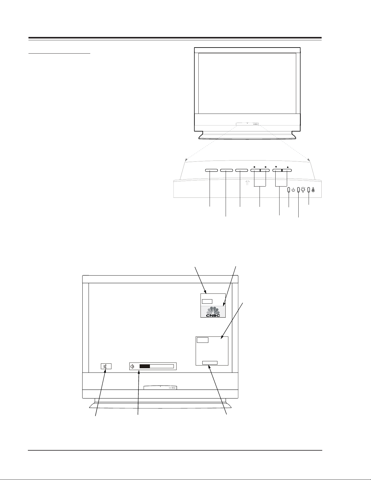
FRONT PANEL CONTROLS
1) Power On / Off
2) Menu
3) Enter (Same as ENTER buttons on your remote control)
4) VOLUME Up / Down
5) CHANNEL Up / Down
6) Operation indicater.
7) Lamp indicater.
8) Temperature indicater.
menupower enter vol ch
Main Ch annel Disp lay:
Displays curr ent channel number.
10
1
2
hannel Label:
If a channel label has been
set, then it will appear here.
Ch. 13
MONO
Ch.6
AM 03:00
3
PIP Dis play:
This display
appears when
PIP is active.
4
6
5
8
7
Mute:
Appears
when sound
is muted.
D60WLCD - 923-03486 1-2 094A - OVERVIEW
Vo lu m e:
Volume level is displayed while
adjusting t he sound.
Tim e:
Appears when
pressing the
enter button on
remote control.
Page 7
OVERVIEW
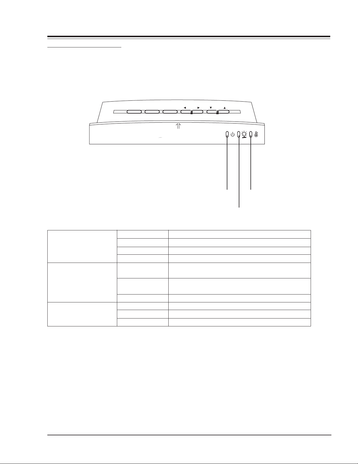
FUNCTION STATUS INDICATORS
Lamp indicator, operation indicator, and temperature
indicator, located below the front panel controls reveal
the operating status of the LCD projection TV.
menupower enter vol ch
Operation Indicator
Lamp Indicator
Temperature Indicator
Operation Indicator
Lamp Indicator
Off
Red
Green
Orange (Flashing)
Orange
Red (Flashing) There is a problem with the lamp or around it. Contact
Green (Flashing) The lamp cover is not closed.
Orange The projector is overheating.
Red The projector shutdown due to overheating.
Red (Flashing) The projector shutdown, check the cooling fan.
Power is not connected.
Power Cord is connected, unit is on standby.
On
Preparing operation in standby.
Projection lamp is nearing the end of its life and needs
to be replaced with a new lamp.
an authorized service center.
Temperature Indicator
D60WLCD - 923-03486 1-3 094A - OVERVIEW
Page 8
P
S
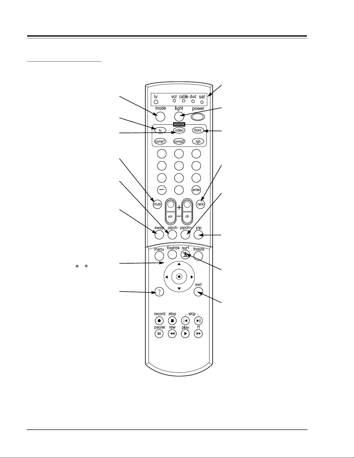
REMOTE CONTROL
REMOTE BUTTON DESCRIPTIONS
REMOTE CONTROL
Selects the remote operating mode:
TV, VCR, Cable, DVD and Satellite.
TV
MODE
Selects the analog TV signal.
VIDEO
Toggles between Video 1 and
Video 2 input sources.
MUTE
Switch the sound on or off
PIP CH -
Changes to next lower PIP
channel
SWAP
Swap the signal from
your PIP window to
the main screen.
THUMBSTICK
Allows you to navigate the on-
screen menus and to adjust the
system settings and preferences,
by moving to an option with the
arrows and
option with . If is pressed while
selecting the highlighted
you are in normal viewing, the
information banner is displayed.
1 2 3
4 5 6
7 8 9
0
INDICATOR LIGHT
Show active remote mode
every time any button is
pressed.
LIGHT
Illuminates the remote control keys.
FRONT
Selects the front video signal if a device, such as a
camcorder or game player,
is connected to the front
video input jack.
RAT IO
Changes the screen format
or aspect ratio.
PIP CH +
Changes to next higher PI
channel.
PIP
Toggles between PIP, POP
(Picture-out-of-Picture) and
Split screen.
SURF
Scrolls the Surf channel
list.
Brings up the on-screen EZ
Help menu while you are in
normal viewing.
D60WLCD - 923-03486 1-4 094A - REMOTE
EXIT
Clears all on-screen displays and returns to TV
viewing from any menu.
HELP
Page 9

REMOTE BUTTON DESCRIPTIONS
-
Select other operating modes, for
the remote to control external
COMPONENT 1, 2
MODE BUTTONS
Selects component signal sources,
such as DVD or HD receiver.
For direct channel selection and
Is used to enter a program number
NUMBER KEYPAD
programming functions.
for multiple program channels.
VOLUME UP/DOWN
Increases/decreases the sound
devices.
“DASH” BUTTON
level.
REMOTE CONTROL
1 2 3
4 5 6
7 8 9
0
POWER
Turns your Entertainment
Machine or any other programmed equipment on or
off, depending on mode.
RGB
Selects PC or RGB input
sources.
ENTER
Selects the highlighted option
in the menu system or onscreen displays.
CHANNEL UP/DOWN
Scrolls through available chan
nels in EZ Scan memory.
FLASH BK
Tunes to the last channel
viewed.
Brings up the main menu
MENU
to the screen.
RECORD, PAUSE, REW,
FFWD, PLAY, STOP
Control the functions on your VCR.
FREEZE
Captures and freezes the
currently-viewed screen in
PIP.
ENTER
When in the menu system
and other on-screen displays, selects high lighted
options.
SKIP
Works as a song selector
in audio mode and a movie
chapter selector in
aux/DVD mode.
D60WLCD - 923-03486 1-5 094A - REMOTE
Page 10

REMOTE CONTROL
Brand Codes
ABC 003 004 039
042 046 052
053
ANTRONIK 014
ARCHER 005 007 014
024
CABLE STAR 026
CENTURION 092
CENTURY 007
CITIZEN 007
COLOUR VOICE 065 090
COMBANO 080 081
COMTRONICS 019 030
DIAMOND 023
EAGLE 020 030 040
EASTERN 057 062 066
ELECTRICORD 032
GE 072
GEMINI 008 022 025
054
GI 052 074
GOLDEN CHANNEL 030
HAMLIN 049 050 055
HITACHI 052 055
HOSPITALITY 070 077
JERROLD 002 003 004
Brand Codes
008 009 010
052 069 074
LG 255
M-NET 037
MACOM 033
MAGNAVOX 010 012 064
079
MEMOREX 001
MOVIE TIME 028 032
NSC 015 028 038
071 073
OAK 016 031 037
053
PANASONIC 044 047
PARAGON 001
PHILIPS 006 012 013
020 065 085
090
PIONEER 034 051 052
063 076
POST NEWS WEEK 016
PRUCER 059
PTS 011 048 071
072 073 074
PULSAR 001
RCA 047
Brand Codes
REGAL 049 050
REGENCY 057
REMBRANT 025
RK 091
SAMSUNG 030 068
SCIENTIFIC ATLANTA 003 011 041
042 043 045
046
SHERITECH 022
SIGNAL 030
SIGNATURE 052
SL MARX 030
SPRUCER 047 078
STARCOM 002 004 008
009
STARGATE 008 030
SYLVANIA 067
TADIRAN 030
TANDY 017
TEXSCAN 029 067
TOCOM 039 040 056
TOSHIBA 001
UNIKA 007 014 024
UNITED CABLE 004 053
UNIVERSAL 005 007 014
024 026 027
Brand Codes
032 035
VIEWSTAR 012 015 018
086 087 088
089
ZENITH 001 060 093
PROGRAMMING THE REMOTE
The remote control of your HD receiver is a multibrand
or universal remote control that can be programmed to
operate most remote-controllable components of other
manufacturers. Note that the remote control may not
control all models of other brands.
To find out whether your remote control can operate the
component without programming, turn on the
component such as the VCR and press the corresponding
mode button (VCR) on the remote control while pointing
at the component. Test the POWER and CH +/- buttons
to see if the component responds properly. If not, the
remote requires programming to operate the device.
Turn on the component to be programmed. Then press
the corresponding mode button on the remote control.
Press the POWER button and the MUTE button
simultaneously. Then the remote control is ready to
program the code for the corresponding component.
There are two ways to find the right code for the
component.
A. If you press the CH +/- buttons repeatedly, the code
will change one at a time. Press the POWER button after
each code change. If the right code is found, the device
will turn off.
B. Enter a code number using the number buttons on
the remote. The right code numbers for the corresponding
component can be found on the following pages. Again,
if the code is correct, the device will turn off.
Press the EXIT button to store the program. Test the
remote control functions to see if the component
responds properly. If not, repeat from step 2.
CABLE BOX CODES
D60WLCD - 923-03486 1-6 094A - REMOTE
Page 11

TV CODES
Brand Codes
A MARK 112 143
ADMIRAL 072 081 161
AKAI 006 146
AMPRO 073 167
AMSTRAD 052
ANAM 043 054 056
080 104 108
112 115 118
121 131
AOC 004 006 058
112
BLAUPUNKT 088
CANDLE 002 003 004
006
CAPEHART 058
CETRONIC 043
CITIZEN 002 003 004
006 043 101
103 143
CLASSIC 043
CONCERTO 004
CONTEC 039 043 050
051
CORONADO 143
CRAIG 043 054
CROWN 043 143
CURTIS MATHES 004 006 101
116 143
CXC 043
DAEWOO 004 016 017
043 044 055
071 076 103
107 111 114
117 120 123
125 127 128
136 143
DAYTRON 004 116 143
DYNASTY 043
DYNATECH 062
ELECTROHOME 024 077 143
EMERSON 004 005 006
028 043 047
048 050 051
096 116 143
151 153 154
155
FISHER 007 057
FUNAI 028 043
FUTURETECH 043
GE 004 006 008
009 034 056
073 074 091
116 130 144
155 160 161
165
Brand Codes
GOLDSTAR 004 102 106
110 112 113
116 119 122
127 137 143
HALL MARK 004 116
HITACHI 004 006 009
010 011 012
023 041 075
143 158 163
166
INFINITY 164
INKEL 129
JBL 164
JCPENNY 004 006 008
009 024 030
065 101 143
156 160
JENSEN 013
JVC 034 038 070
083 145
KEC 043
KENWOOD 006 070
KLOSS 002 059
KMC 143
KTV 006 043 143
154
LG 255
LODGENET 072
LOGIK 072
LUXMAN 004
LXI 007 015 052
081 160 164
166
MAGNAVOX 003 004 006
022 059 060
061 063 064
127 143 160
164
MARANTZ 006 077 164
MATSUI 164
MEMOREX 004 007 072
116
METZ 088
MGA 004 006 024
028 042 049
077 116
MINERVA 088
MITSUBISHI 004 006 024
028 040 042
109 116 124
146
MTC 004 006 062
101
NAD 015 025
NEC 006 007 016
Brand Codes
019 024 040
056 130 132
134
NIKEI 043
ONKING 043
ONWA 043
OPTONICA 019 081
PANASONIC 034 056 080
092 164
PHILCO 003 004 006
024 043 056
059 060 063
064 127 143
164
PHILIPS 003 004 005
006 038 059
070 093 143
160 164
PIONEER 006 018 023
025 027 116
135 176
PORTLAND 004 143
PROSCAN 144 160 161
165 167
PROTON 004 058 116
131 143 171
173
QUASAR 034 056 092
RADIO SHACK 019 043 047
116 127 143
RCA 004 006 023
024 056 065
074 144 152
156 160 161
165
REALISTIC 007 019 043
047
ROCTEC 186
RUNCO 168 169
SAMPO 004 006 058
116
SAMSUNG 004 050 089
101 105 113
116 127 133
137 143 160
SANYO 007 020 021
033 039 053
057 082 166
SCOTT 004 028 043
048 116 143
SEARS 004 007 015
028 030 057
082 094 101
116 143 160
Brand Codes
Sharp 004 014 019
022 028 029
081 143 170
175
SIEMENS 088
SIGNATURE 072
SONY 041 070 079
085 126 139
147 185
SOUNDESIGN 003 004 028
043 116
SPECTRICON 112
SSS 004 043
SUPRE MACY 002
SYLVANIA 003 004 006
044 059 060
063 064 116
127 140 160
164
TANDY 081
TATUNG 056 062
TECHNICS 034 080 084
TECHWOOD 004
TEKNIKA 002 003 004
006 024 028
031 043 072
077 101 103
143
TELEFUNKEN 037 046 086
087
TELERENT 072
TERA 172
TMK 004 116
TOSHIBA 007 015 030
040 051 062
101 138
TOTEVISION 143
UNIVERSAL 008 009
VIDEO CONCEPTS 146
VIDIKRON 174
VIDTECH 004 116
WARDS 004 008 009
019 028 060
061 063 064
072 074 116
143 164
YAMAHA 004 006
YORK 004 116
YUPITERU 043
ZENITH 001 072 073
095 103 157
ZONDA 112
REMOTE CONTROL
D60WLCD - 923-03486 1-7 094A - REMOTE
Page 12

VCR CODES
Brand Codes
AIWA 034
AKAI 016 043 046
124 125 146
AMPRO 072
ANAM 031 033 103
AUDIO DYNAMICS 012 023 039
043
BROKSONIC 035 037 129
CANON 028 031 033
CAPEHART 108
CRAIG 003 040 135
CURTIS MATHES 031 033 041
DAEWOO 005 007 010
064 065 108
110 111 112
116 117 119
DAYTRON 108
DBX 012 023 039
043
DYNATECH 034 053
ELECTROHOME 059
EMERSON 006 017 025
027 029 031
034 035 036
037 046 101
129 131 138
153
FISHER 003 008 009
010
FUNAI 034
GE 031 033 063
072 107 109
144 147
GO VIDEO 132 136
GOLDSTAR 012 013 020
101 106 114
123
HARMAN KARDON 012 045
HITACHI 004 018 026
034 043 063
137 150
INSTANTREPLAY 031 033
JCL 031 033
JCPENNY 012 013 015
033 040 066
101
JENSEN 043
JVC 012 031 033
043 048 050
Brand Codes
055 060 130
150 152
KENWOOD 014 034 039
043 047 048
LG 255
LLOYD 034
LXI 003 009 013
014 017 034
101 106
MAGIN 040
MAGNAVOX 031 033 034
041 067 068
MARANTZ 012 031 033
067 069
MARTA 101
MATSUI 027 030
MEI 031 033
MEMOREX 003 010 014
031 033 034
053 072 101
102 134 139
MGA 045 046 059
MINOLTA 013 020
MITSUBISHI 013 020 045
046 049 051
059 061 151
MTC 034 040
MULTITECH 024 034
NEC 012 023 039
043 048
NORDMENDE 043
OPTONICA 053 054
PANASONIC 066 070 074
083 133 140
145
PENTAX 013 020 031
033 063
PHILCO 031 034 067
PHILIPS 031 033 034
054 067 071
101
PILOT 101
PIONEER 013 021 048
PORTLAND 108
PULSAR 072
QUARTZ 011 014
QUASAR 033 066 075
145
RCA 013 020 033
Brand Codes
034 040 041
062 063 107
109 140 144
145 147
REALISTIC 003 008 010
014 031 033
034 040 053
054 101
RICO 058
RUNCO 148
SALORA 014
SAMSUNG 032 040 102
104 105 107
109 112 113
115 120 122
125
SANSUI 022 043 048
135
SANYO 003 007 010
014 102 134
SCOTT 017 037 112
129 131
SEARS 003 008 009
010 013 014
017 020 031
042 073 081
101
SHARP 031 054 149
SHINTOM 024
SONY 003 009 031
052 056 057
058 076 077
078 149
SOUNDESIGN 034
STS 013
SYLVANIA 031 033 034
059 067
SYMPHONIC 034
TANDY 010 034
TATUNG 039 043
TEAC 034 039 043
TECHNICS 031 033 070
TEKNIKA 019 031 033
034 101
THOMAS 034
TMK 006
TOSHIBA 008 013 042
047 059 082
112 131
Brands Codes
TOTEVISION 040 101
UNITECH 040
VECTOR RESEARCH 012
VICTOR 048
VIDEO CONCEPTS 012 034 046
VIDEOSONIC 040
WARDS 003 013 017
024 031 033
034 040 053
054 131
YAMAHA 012 034 039
043
ZENITH 001 034 048
056 058 072
080 101
REMOTE CONTROL
D60WLCD - 923-03486 1-8 094A - REMOTE
Page 13

SATELLITE BOX CODES
Brand Codes
ALPHASTAR DSR 123
AMPLICA 050
BIRDVIEW 051 126 129
BSR 053
CAPETRONICS 053
CHANNEL MASTER 013 014 015
018 036 055
CHAPARRAL 008 009 012
077
CITOH 054
CURTIS MATHES 050 145
DRAKE 005 006 007
010 011 052
112 116 141
DX ANTENNA 024 046 056
076
ECHOSTAR 038 040 057
058 093 094
095 096 097
098 099 100
122
ELECTRO HOME 089
EUROPLUS 114
FUJITSU 017 021 022
Brand Codes
027 133 134
GENERAL INSTRUMENT 003 004 016
029 031 059
101
HITACHI 139 140
HOUSTON TRACKER 033 037 039
051 057 104
HUGHES 068
HYTEK 053
JANIEL 060 147
JERROLD 061
KATHREIN 108
LEGEND 057
LG 255
LUTRON 132
LUXOR 062 144
MACOM 010 059 063
064 065
MEMOREX 057
NEXTWAVE 028 124 125
NORSAT 069 070
PACE SKY SATELLITE 143
PANASONIC 060 142
PANSAT 121
Brand Codes
PERSONAL CABLE 117
PHILIPS 071
PICO 105
PRESIDENT 019 102
PRIMESTAR 030 110 111
PROSAT 072
RCA 066 106
REALISTIC 043 074
SAMSUNG 123
SATELLITE SERVICE CO 028 035 047
057 085
SCIENTIFIC ATLANTA 032 138
SONY 103
STARCAST 041
SUPER GUIDE 020 124 125
TEECOM 023 026 075
087 088 090
107 130 137
TOSHIBA 002 127
UNIDEN 016 025 042
043 044 045
048 049 078
079 080 086
101 135 136
Brand Codes
VIEWSTAR 115
WINEGARD 128 146
ZENITH 001 081 082
083 084 091
120
Brand Codes
APEX DIGITAL 022
DENON 020 014
GE 005 006
GOLDSTAR 010 016 025
HARMAN KARDON 027
JVC 012
LG 001 010 016
Brand Codes
025
MAGNAVOX 013
MARANTZ 024
MITSUBISHI 002
NAD 023
ONKYO 008 017
PANASONIC 003 009
Brand Codes
PHILIPS 013
PIONEER 004 026
PROCEED 021
PROSCAN 005 006
RCA 005 006
SAMSUNG 011 015
SONY 007
Brand Codes
THOMPSON 005 006
TOSHIBA 019 008
YAMAHA 009 018
ZENITH 010 016 025
REMOTE CONTROL
DVD CODES
D60WLCD - 923-03486 1-9 094A - REMOTE
Page 14
USER MENUS
USER MENUS
EZ HELP
EZ Help was created as an aid for you to understand
menu functions in an easy and convenient way. When
you navigate through the Menu, press and hold the HELP
(?) button on your remote control to learn about the
highlighted option or feature, information about the
highlighted option will be displayed on the right side
of the TV screen. Press and hold HELP (?) to see the
highlighted information.
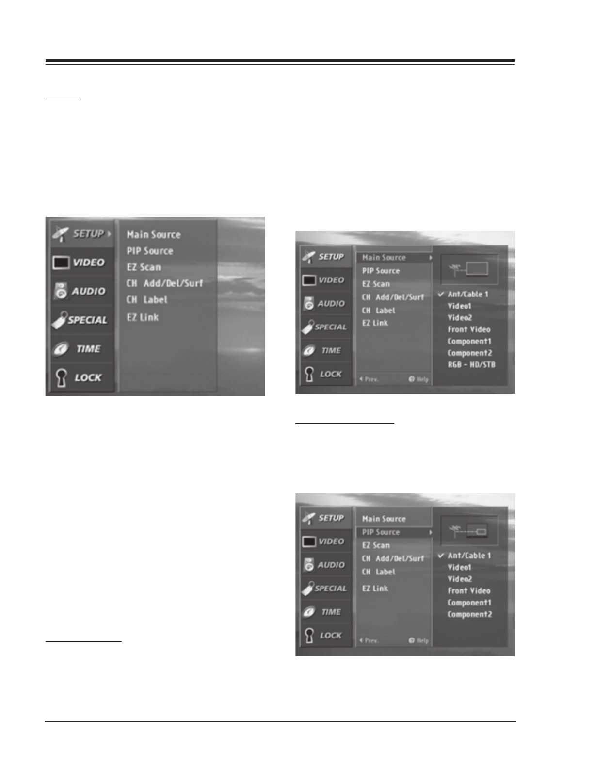
on the remote control, then use the UP/DOWN arrow
button to select the Setup menu.
Press ENTER or the RIGHT arrow button to access the
Setup menu. Use the UP/DOWN arrows to select Main
source. Press ENTER or the RIGHT arrow to access the
Main source menu, then use the UP/DOWN arrow button
to select the source. Your picture source options are:
Ant/Cable 1 (Ant/Cable 2), Video 1,Video 2, Front Video,
Component 1,Component 2, RGB-PC and RGB-HD/STB.
Press EXIT to save and return to TV viewing or press the
LEFT arrow to save and return to the previous Menu. Not
all sources are available for PIP.
The HELP (?) button on the remote control can be used
in two ways. You can press the HELP (?) button
independently to display the EZ HELP feature. When a
MENU is already displayed, you can press the HELP (?) to
go to the EZ HELP feature.
To use the EZ Help feature:
1. Press the HELP (?) button on the remote control to
display the EZ Help menu.
2. Scroll up and down to select EZ Help menu options
using the Up and Down Arrows on the remote control thumb stick.
3. Move the highlight by using the thumb stick. The
explanations of the highlighted option will be displayed on the right side or at the bottom of the
screen.
4. Press the EXIT button on the remote control to return to TV viewing.
SOURCE SELECTION
Changes the picture source for the main screen so you
can watch your off-air TV, cable TV, VCR, DVD, or any
other devices that you have hooked up to your TV. You
can also change the picture source with the Source
buttons on the remote control. Press the MENU button
PIP/POP/SPLIT SOURCES
PIP (Picture-in-Picture) / POP (Picture-out-of-Picture)
/ SPLIT modes let you watch main and sub pictures at
the same time. PIP/POP/SPLIT modes turn off in instances
indicated below.
D60WLCD - 923-03486 1-10 094A - MENUS
Page 15
USER MENUS
· Changing main source
· Changing Aspect Ratio
· Activating Channel Add/Del/Surf, Channel Label or
Channel Block in Setup menu
· Activating Help menu
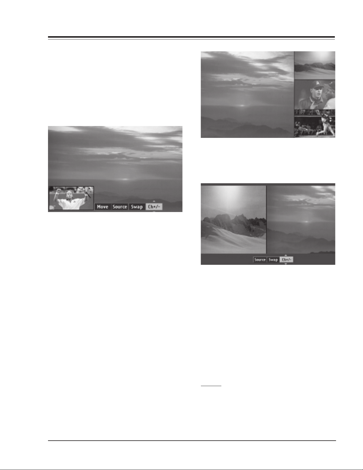
PIP
Press the PIP button on the remote control to activate
PIP (Picture in Picture) mode. Press the LEFT/RIGHT
arrow to select CH+/-, Swap, Source or Move.
Press the EXIT button to exit POP mode or press the
PIP button again to activate Split mode. Press the
LEFT/RIGHT arrow in Split mode to select CH+/-, Swap,
or Source.
CH+/-: Use the UP/DOWN arrow to select a program
for the sub picture. Changing programs on
the sub picture is only possible if the PIP
signal source is NTSC RF signal. If you want to
change the program on the main picture, press
ch +/- button.
Swap: Use the UP/DOWN arrow to swap main and sub
picture.
Source: Use the UP/DOWN arrow to select a source for
sub picture. Your choices are: TV, Video 1/2,
Front, Component 1/2. RGB-HD/STB and RGBPC input sources cannot used as PIP screen
source.
Move: Use the UP/DOWN arrow to move the sub pic-
ture on the screen.
Press the EXIT button to exit PIP mode or press the
PIP button again to activate POP mode.
POP
Press the PIP button on the remote control while in
PIP mode to activate POP (Picture out-of-Picture)
mode.
CH+/-: Use the UP/DOWN arrow to select a program
for the sub picture. Changing programs in the
sub picture is only possible if the PIP source
is NTSC RF signal. To change the program for
the main picture, use ch +/- button.
Swap: Use the UP/DOWN arrow to swap main and sub
pictures.
Source: Use the UP/DOWN arrow to select a source for
sub picture. Your choices are: TV, Video 1/2,
Front, Component 1/2. RGB-PC input cannot
used for the PIP picture source.
Press the EXIT button to exit Split mode. Press the
FREEZE button to capture and freeze the currently
viewed sub picture in PIP or Split mode.
EZ SCAN
Press the MENU button on the remote control, then use
the UP/DOWN arrow button to select the Setup menu.
Press ENTER or the RIGHT arrow button to access the
Setup menu. Use the UP/DOWN arrows to select EZ Scan.
D60WLCD - 923-03486 1-11 094A - MENUS
Page 16

USER MENUS
Press ENTER or the RIGHT arrow to access the EZ Scan
menu, then use the UP/DOWN arrows to select: ANT1 Air,
ANT1 Cable, ANT2 Air or ANT2 Cable. Press ENTER or the
Right arrow button to start the EZ Scan channel search.
CHANNEL ADD/DEL/SURF
There are two different types of channel lists in memory:
“Custom list” and “Surf list” from the default channel list
made in the EZ SCAN menu.
You can create your own Surf list with up to 16 channels.
It appears at the bottom-left corner of the screen. Press
the Surf button on the remote control when a channel is
highlighted to add or delete the channel in the Surf list.
Press EXIT to save and return to TV viewing or press
MENU to save and return to the previous menu.
CHANNEL LABEL SETUP
Choose preset labels for your channels. Use Channel +/on your remote control in the CH Label menu to select a
channel for labeling, and choose a suitable label for your
channel by pressing to set the label to the selected
channel.
A custom list can be created by toggling each channel
on or off with (Enter). Once a channel is highlighted,
you will be able to see whether the channel is currently
added or deleted by referring to the small window at the
top-left corner of the screen.
D60WLCD - 923-03486 1-12 094A - MENUS
Press the MENU button on the remote control, then use
the UP/DOWN arrow button to select the SETUP menu.
Press ENTER or the RIGHT arrow button to access the
SETUP menu. Use the UP/DOWN arrows to select the CH
Label option. Press ENTER or the RIGHT arrow to access
the CH Label menu.
Page 17

USER MENUS
You will now see a screen filled with Labels and a preview
screen. Use channel UP/DOWN button on your remote to
select the a channel to Label. Use the UP/DOWN and
LEFT/RIGHT arrows to select the appropriate label for
the channel and press ENTER to set the Label to the
selected channel. Repeat 5 and 6 steps until all channels
are Labeled. Press EXIT to save and return to TV viewing.
EZ LINK
Lets you link the Zenith’s READY TV (Model: D60WLCD)
and Zenith’s high definition set set-top box for DIRECTV
via an RS-232C cable.
After installing EZ link, you can control a set-top box
for DIRECTV with a remote control of Zenith’s READY TV.
Press the MENU button on the remote control, then use
the UP/DOWN arrow button to select the Setup menu.
Press ENTER or the RIGHT arrow button to access the
Setup menu. Use the UP/DOWN arrows to select EZ link
and then press ENTER or the RIGHT arrow button. Use
the UP/DOWN arrows to choose On or Off. Press EXIT to
save and return to TV viewing or press the LEFT arrow to
save and return to the previous Menu.
VIDEO MENU
Lets you adjust the picture appearance to suit your
preference and viewing situations. You can manually
adjust the levels of picture quality settings, such as
Contrast, Brightness, Sharpness, etc. You can also select
the preset value in the EZ Video menu based on the
program category.
Press the MENU button on the remote control, then use
the UP/DOWN arrow button to select the VIDEO menu.
Press ENTER or the RIGHT arrow button to access the
VIDEO menu. Use the UP/DOWN arrows to select one of
the following options.
Your options are:
Contrast: Adjusts the difference between the light and
dark levels of the picture. Press the right arrow
button to activate adjusting.
Brightness: Adjusts the white or light level of the over-
all picture.
Sharpness: Adjusts the level of crispness in the edges
between the light and dark areas of the picture.
The lower the level, the softer the image.
Color: Adjusts the intensity of all colors.
Tint: Adjusts the balance between the red and green
levels.
EZ Video: Lets you choose the preset value of the pic-
ture settings. Custom: Lets you adjust the picture
settings manually. Normal: Restores the levels to
their original picture settings. Movie Adjusts Video
settings to enhance Movie viewing. Contrast and
Sharpness levels are lowered so that the picture
looks warm and soft. Video Game: Sets the picture
settings to the levels that are more suitable to
enjoy games. Color, Contrast and Sharpness levels
are lowered to reduce the amount of glare.
D60WLCD - 923-03486 1-13 094A - MENUS
Page 18
USER MENUS
Sports: Sets the picture settings to the levels that are
more suitable to view sporting events. Contrast
and Color levels are raised so that an action scene
appears clear and brilliant. Weak Signal: Adjusts
the picture settings to compensate for a weak signal
reception. Contrast, Color and Sharpness levels are
lowered to hide the picture imperfections. Daylight: Increases the levels of all picture settings
to fit daylight conditions.
Use the LEFT/RIGHT arrows to adjust the option to your
preference. Press ENTER to save your choices and return
to the previous menu or use the UP/DOWN arrows to
select another option.
AUDIO MENU
Lets you adjust the sound to. Press the MENU button
on the remote control, then use the UP/DOWN arrow
button to select the AUDIO menu.
Stadium: Stresses high frequency sounds and front
surround sound to create the sensation you would
experience in a stadium.
News: Increase high frequency sounds to emphasize the human voice.
Music: Increase both high and low frequency sounds
to stress the sounds of musical instruments.
Theater: Stresses both high and low frequency
sounds, in addition to the front surround sound,
to create the sensation you would experience in a
theater.
EZ SoundRite: Scans for changes in sound level
during commercials, then adjusts the sound to
match the current audio level of the TV program
you are watching.
Audio Mode: Lets you choose the default audio
mode for conventional analog programs. When you
hear a program broadcast in mono, you will hear
only monaural sound, even though Stereo mode is
set. When Second Audio Program (SAP) mode is
set, the program’s second audio program, usually
the program’s dialog in another language, (if provided), is broadcast in mono.
Front Surround: Increases the front surround sound
to create more open and expanded sound.
Internal Speaker: Allows you to toggle the TV internal speakers Stereo, Center or off. If you want
to use your external hi-fi stereo system, turn off
the internal TV speakers. However, you may use
the internal TV speakers as a center speaker to
create a surround effect.
Use the UP/DOWN arrows to select your preference (Bass,
Treble, Balance), and then use the LEFT/RIGHT arrows
Press ENTER or the RIGHT arrow button to access the
AUDIO menu. Use the UP/DOWN arrows to select one of
the following options. Your options are:
Bass: Increases or decreases the lower frequency
sounds of the TV speakers.
Treble: Increases or decreases the higher frequency
sounds of the TV speakers. Increases in treble, for
example, make voice or string sounds stand out
Balance: Lets you adjust the left to right balance
of the TV speakers.
EZ Sound: Lets you choose the sound settings
manually.
Custom: Lets you adjust the Audio menu sound
options manually.
Normal: Restores the sound levels to their original
settings.
D60WLCD - 923-03486 1-14 094A - MENUS
to adjust the option to your preference. Press ENTER to
save your choices and return to the previous menu.
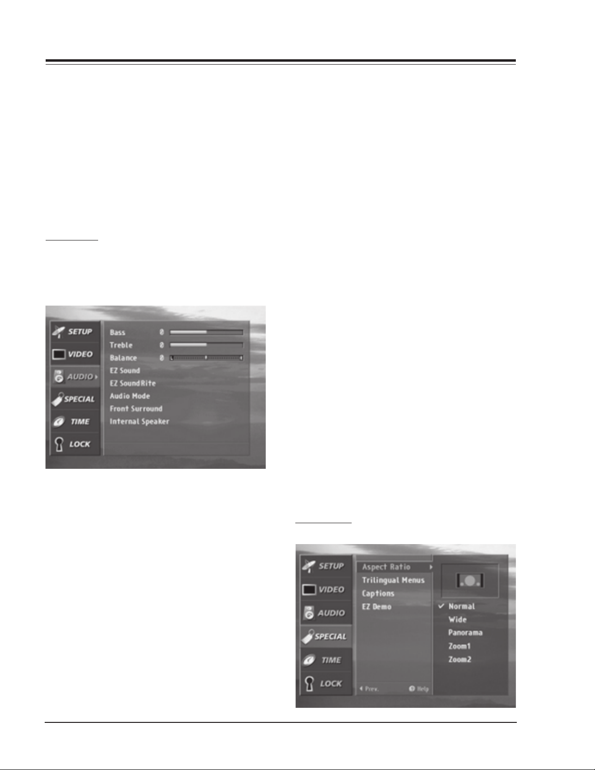
ASPECT RATIO
Page 19
USER MENUS
When you receive an analog picture with a 4:3 aspect
ratio, you need to specify how the picture is to be
displayed. Press the MENU button on the remote control,
then use the UP/DOWN arrow button to select the
SPECIAL menu. Or press the RATIO button to instantly
access the Aspect Ratio menu. Press ENTER or the RIGHT
arrow button to activate the Special menu. Use the UP/
DOWN arrows to choose Aspect Ratio. Press ENTER or the
RIGHT arrow button to move into the Aspect Ratio
selection menu.
Use the UP/DOWN arrow buttons to select the right ratio
for your viewing environment:
Normal - Choose when you want to view a picture with
an original 4:3 aspect ratio, with black bars appearing at both the left and right sides.
Wide - Choose when you want to adjust the picture
horizontally, in linear proportion to fill the entire
screen. (Useful for viewing 4:3 formatted DVDs.)
Panorama - Choose when you want to adjust the pic-
ture in a non-linear proportion, that is, more enlarged at both sides, to create a spectacular view.
Zoom1 - Choose when you want to view the picture
without any alteration. However, the top and bottom portions of the picture will be cropped.
Zoom2 - Choose when you want the picture to be al-
tered, both horizontally extended and vertically
cropped. The picture taking a halfway trade off
between alteration and screen coverage. Press EXIT
to save and return to TV viewing or press the ENTER button to save and return to the previous
menu.
ON-SCREEN MENUS LANGUAGE
Lets you select your preferred language for the menus,
English, Spanish, or French.
Press the MENU button on the remote control, then use
the UP/DOWN arrow button to select the Special menu.
Press ENTER or the RIGHT arrow button to activate the
Special menu. Use the UP/DOWN arrows to choose
Trilingual Menus. Press ENTER or the RIGHT arrow button
to move into the Language selection menu. Use the
UP/DOWN arrow button to select the language you wish
to view on your on-screen menus. Press EXIT to save
and return to TV viewing or press the ENTER button to
save and return to the previous menu.
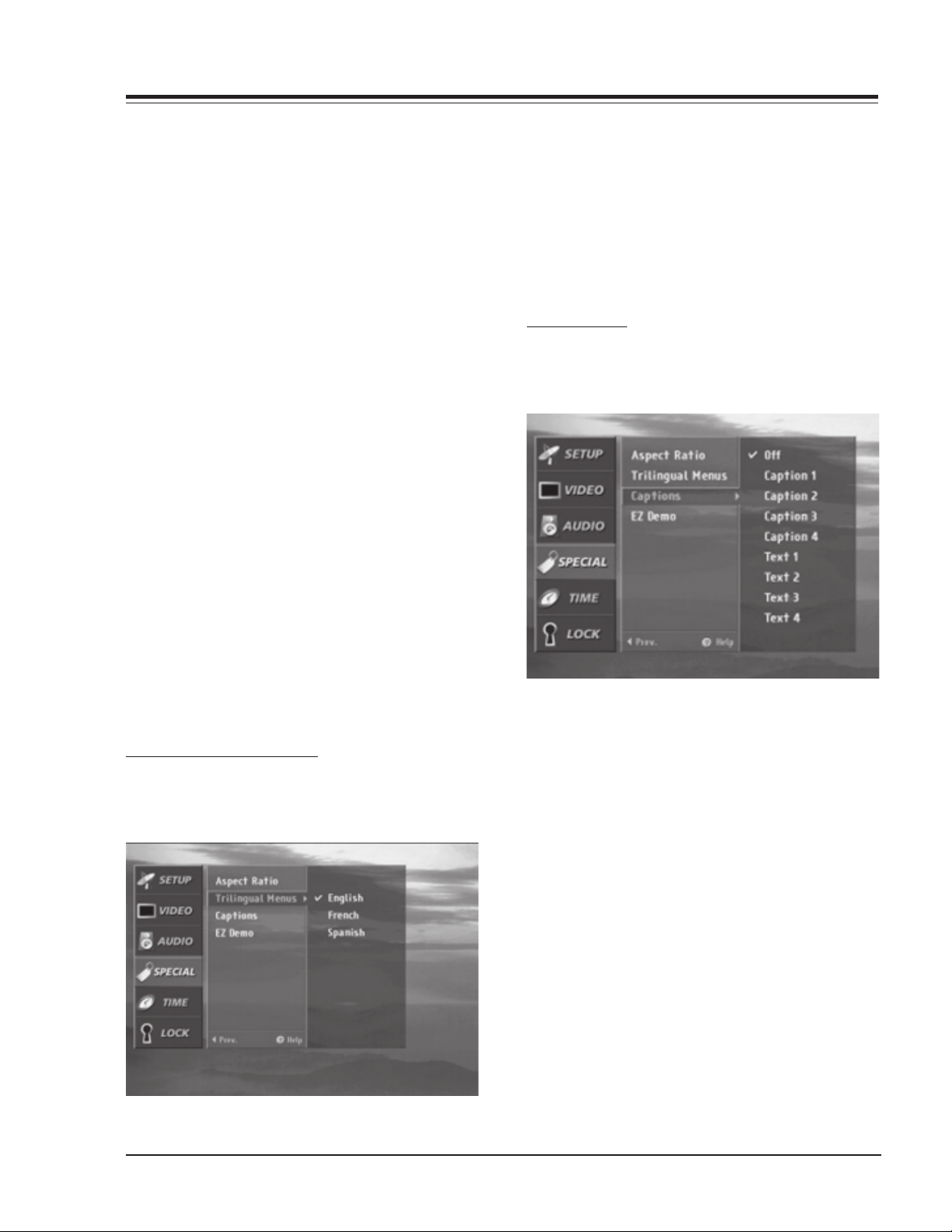
CAPTIONS/TEXT
Lets you select a closed caption mode for displaying
captioning information when provided on the program.
Closed Caption (CC) displays information at any position
on the screen, usually the program’s dialog. Text displays
information, usually at the bottom position and is used
for a data service, generally not program related. Press
the MENU button on the remote control, then use the
UP/DOWN arrow button to select the SPECIAL menu.
Press ENTER or the RIGHT arrow button to activate the
SPECIAL menu. Use the UP/DOWN arrows to choose
Captions, then press ENTER or the Right arrow button.
Use the UP/DOWN arrow buttons to make your caption
selection. Your choices are: Off, Caption 1, Caption 2,
Caption 3, Caption 4, Text 1, Text 2, Text 3 and Text 4.
Press EXIT to save and return to TV viewing or press the
ENTER button to save and return to the previous menu.
D60WLCD - 923-03486 1-15 094A - MENUS
Page 20
USER MENUS
EZ DEMO
Shows you how to navigate the on-screen menus of your
TV.
Press the MENU button on the remote control, then use
the UP/DOWN arrow button to select the SPECIAL menu.
Press ENTER or the RIGHT arrow button to activate the
SPECIAL menu. Use the UP/DOWN arrows to choose EZ
Demo, then press ENTER or the RIGHT arrow button to
activate EZ Demo. Press exit button on the remote to
stop EZ Demo.
then press ENTER or the RIGHT arrow button to activate
the Auto Clock option then use the UP/DOWN arrow
button to make your auto clock selection. Use the
number buttons to set the PBS channel.
Time Zone - Lets you select the time zone of your viewing
area. Daylight Savings - Lets you set Daylight Savings
On or Off, depending on whether or not your viewing
area observes Daylight Savings.
If you select Auto Clock, use the RIGHT arrow to choose
On or off. If you select on, select the SET and then press
the ENTER button. If you select off, press EXIT to return
to TV viewing or press the ENTER button to save and
return to the previous menu. Your choices are saved
when Auto Clock is set.
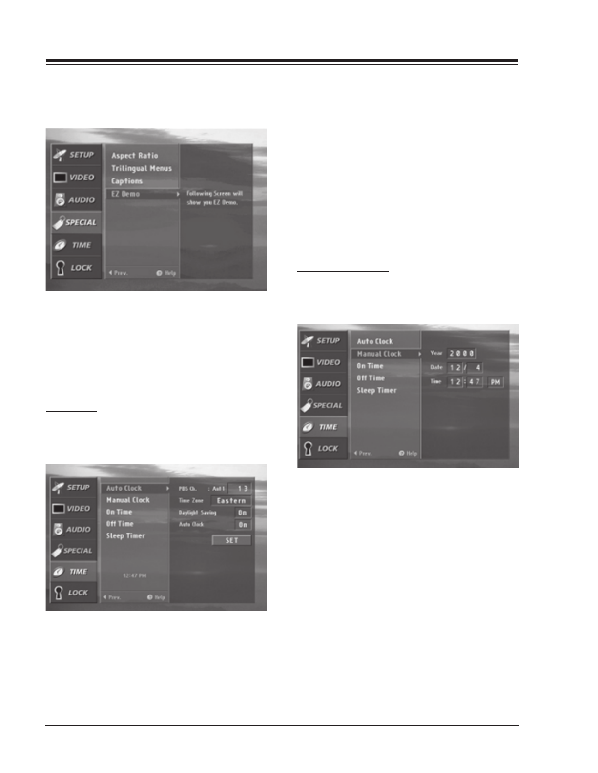
MANUAL CLOCK SETUP
Enables you to enter the time using the number buttons
on your remote control.
AUTO CLOCK
Sets the time automatically through the PBS broadcast
signal.
The PBS channel signal includes information for the
correct time. Enter the local PBS channel number with
the number buttons on your remote control. Press the
MENU button on the remote control, then use the UP/
DOWN arrow button to select the TIME menu. Press ENTER
or the RIGHT arrow button to activate the TIME menu.
Use the UP/DOWN arrow button to choose Auto clock,
Press the MENU button on the remote control, then use
the UP/DOWN arrow button to select the TIME menu.
Press ENTER or the RIGHT arrow button to activate the
TIME menu. Use the UP/DOWN arrow button to choose
Manual Clock, then press the RIGHT arrow to activate
Manual Clock.
Use the UP/DOWN arrows to make your Manual Clock
selection. Your choices are: Year, Date and Time. Use the
number buttons to set the Year, Date and Time. Press
EXIT to save and return to TV viewing or press the ENTER
button to save and return to the previous menu.
D60WLCD - 923-03486 1-16 094A - MENUS
Page 21

USER MENUS
TV TURN ON TIME
Lets you set an automatic turn on time for your TV.
Press the MENU button on the remote control, then use
the UP/DOWN arrow button to select the Time menu.
Press ENTER or the RIGHT arrow button to activate the
Time menu. Use the UP/DOWN arrows to choose On Time
then press the RIGHT arrow to activate On Time. Use
the UP/DOWN arrows to choose On or Off. Use the number
buttons to set the On Time options. Press EXIT to save
and return to TV viewing, or press the ENTER button to
save and return to the previous menu. You must set the
current time before using on/off time function.
TV TURN OFF TIME
Lets you set an automatic daily turn off time for your
TV.
and return to TV viewing, or press the ENTER button to
save and return to the previous menu.
SLEEP TIMER
Lets you select the amount of time before your TV
automatically turns itself off.
Press the MENU button on the remote control, then use
the UP/DOWN arrow button to select the TIME menu.
Press ENTER or the RIGHT arrow button to activate the
TIME menu. Use the UP/DOWN arrows to choose Sleep
Timer then press the RIGHT arrow to activate Sleep Timer.
Use the UP/DOWN arrows to choose a preset turn off
time.
Press EXIT to save and return to TV viewing, or press
the ENTER button to save and return to the previous
menu.
Press the MENU button on the remote control, then use
the UP/DOWN arrow button to select the Time menu.
Press ENTER or the RIGHT arrow button to activate the
Time menu. Use the UP/DOWN arrows to choose Off Time
then press the RIGHT arrow to activate Off Time. Use
the UP/DOWN arrows to choose On or Off. Use the number
buttons to set the Off Time options. Press EXIT to save
D60WLCD - 923-03486 1-17 094A - MENUS
Page 22
USER MENUS
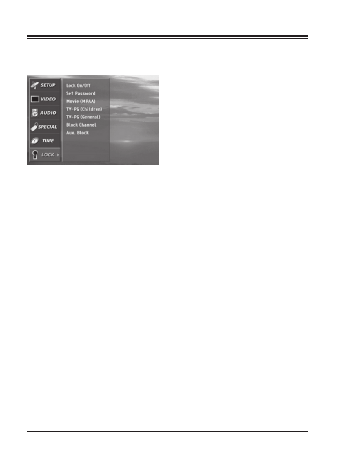
PARENTAL LOCK
Lets you block specific channels, ratings and other
sources based on the blocking schemes.
A password is required to gain access to this menu if
the Lock System is activated. Press the MENU button on
the remote control, then use the UP/DOWN arrow button
to select the LOCK Menu. Press ENTER or the RIGHT arrow
button to activate the LOCK Menu. See the next page
for more details on your blocking options. Use the UP/
DOWN arrows to choose from the following LOCK Menu
options. Lock On/Off: Activates or disables the blocking
scheme you set up previously.
Set Password: Changes the password by inputting a
new password twice.
Movie (MPPA): Blocks movies according to the movie
ratings limit, so children cannot view certain movies. You can see the ratings limit by blocking out
all the movies with the ratings above a specified
level. Keep in mind that the movie ratings limit
only applies to movie shown on TV, not TV programs, such as soap operas.
TV-PG (Children): Keeps children from watching cer-
tain TV programs among only the programs intended for children, according to the ratings limit.
This rating does not apply to other TV programs.
Unless you block certain TV programs intended for
mature audiences in the TV Rating - General menu,
your children may view those programs.
TV-PG (General): Blocks certain TV programs that you
and your family do not want to view, based on the
ratings.
Block Channel: Blocks any channels that you do not
want to view or that you do not want your children to watch.
Aux. Block: Enables you to select a source for block-
ing among the source devices you have hooked
up.
Ratings:
TV-Y7 (Directed to Older Children): This program is
designed for children age 7 and above.
TV-G (General audience): Most parents would find this
program suitable for all ages.
TV-PG (Parental guidance suggested): This program
contains material that parents may find unsuitable for younger children.
TV-14 (Parents strongly cautioned): This program con-
tains some material that many parents would find
unsuitable for children under 14 years of age.
TV-MA (Mature audience only): This program is spe-
cifically designed to be viewed by adults and therefore may be unsuitable for children under 17.
G - (General audiences): All ages admitted.
PG - Parental guidance suggested: Some material may
not be suitable for children.
PG-13 - Parents strongly cautioned: Some material may
not be appropriate for children under 13.
R- (Restricted): Children under 17 require accompa-
nying parent or adult guardian.
NC-17: No one 17 and under admitted.
TV-Y (All Children): This program is determined to be
appropriate for all children.
X: Adult admitted only.
NR: Not rated movie.
D60WLCD - 923-03486 1-18 094A - MENUS
Page 23

section 2
SERVICE MENUS
SERVICE MENU OPTIONS
To access the Service Menu, press and hold the MENU
key until the User Menu display disappears, then press
1937, and then ENTER to access the Service Menu. 0-F
FACT MENU: Use SELECT UP and DOWN Keys to select item
00, the Factory Mode. This item is used by the Factory
when the module is being tested. It has two positions:
0 and 1. In the field, this item should always be left off
(Zero is off).
When this item is off, only the first twenty-two items in
the Service Menu can be accessed. They appear one at a
INSTALLERS MENU
ITEM OSD FUNCTION DEFAULT DESCRIPTION
TA1270AF 1270(M) S-Cont Main Contrast 0-31 Adjustment
1270(S) S-Cont Sub Contrast 0-31 Adjustment
1270(M) S-Colo r Main Color 0-31 Adjustment
1270(S) S-Color Sub Color 0-31 Adjustment
ET2090 2090 R_HOR_POS Horizontal Position 0-511 Adjustment
2090 G_HOR_POS Horizontal Position 0-511 Adjustment
2090 B_HOR_POS Horizontal Position 0-511 Adjustment
M62352 V_REF V-Reference Voltage Adjustment 0-255 Adjustment
R_NRS_H Noise Reduction Signal Adjustment 0-255 Adjustment
G_NRS_H Noise Reduction Signal Adjustment 0-255 Adjustment
B_NRS_H Noise Reduction Signal Adjustment 0-255 Adjustment
R_VCOM Flicker Adjustment 0-255 Adjustment
G_VCOM Flicker Adjustment 0-255 Adjustment
B_VCOM Flicker Adjustment 0-255 Adjustment
GAMMA R R_X0_S_MODE 1 Tone Gray Adjustment 0-1023 Adjustment
R_X1_S_MODE 2 Tone Gray Adjustment 0-1023 Adjustment
R_X2_S_MODE 3 Tone Gray Adjustment 0-1023 Adjustment
R_X3_S_MODE 4 Tone Gray Adjustment 0-1023 Adjustment
R_X4_S_MODE 5 Tone Gray Adjustment 0-1023 Adjustment
R_X5_S_MODE 6 Tone Gray Adjustment 0-1023 Adjustment
R_X6_S_MODE 7 Tone Gray Adjustment 0-1023 Adjustment
R_X7_S_MODE 8 Tone Gray Adjustment 0-1023 Adjustment
R_X8_S_MODE 9 Tone Gray Adjustment 0-1023 Adjustment
R_X9_S_MODE 10 Tone Gray Adjustment 0-1023 Adjustment
R_X10_S_MODE 11 Tone Gray Adjustment 0-1023 Adjustment
R_X11_S_MODE 12 Tone Gray Adjustment 0-1023 Adjustment
R_X12_S_MODE 13 Tone Gray Adjustment 0-1023 Adjustment
R_X13_S_MODE 14 Tone Gray Adjustment 0-1023 Adjustment
R_X14_S_MODE 15 Tone Gray Adjustment 0-1023 Adjustment
R_X15_S_MODE 16 Tone Gray Adjustment 0-1023 Adjustment
time near the middle left of the screen. When this item
is set to 1, 66 menu items are available.
When the Service Menu is on, the AC Power-On feature is
always enabled regardless of the setting of AC ON in the
Service Menu. The TV set will automatically come on when
AC is applied.
Use the remote to reenter the Service Menu to turn the
Service Menu off. The Factory Mode may also be turned
off by setting the clock, or running the Auto Program
feature in the customer Set Up menu.
D60WLCD - 923-03486 2-1 094A - SERVICE MENUS
Page 24

SERVICE MENUS
INSTALLERS MENU
ITEM OSD FUNCTION DEFAULT DESCRIPTION
GAMMA G G_X0_S_MODE 1 Tone Gray Adjustment 0-1023 Adjustment
G_X1_S_MODE 2 Tone Gray Adjustment 0-1023 Adjustment
G_X2_S_MODE 3 Tone Gray Adjustment 0-1023 Adjustment
G_X3_S_MODE 4 Tone Gray Adjustment 0-1023 Adjustment
G_X4_S_MODE 5 Tone Gray Adjustment 0-1023 Adjustment
G_X5_S_MODE 6 Tone Gray Adjustment 0-1023 Adjustment
G_X6_S_MODE 7 Tone Gray Adjustment 0-1023 Adjustment
G_X7_S_MODE 8 Tone Gray Adjustment 0-1023 Adjustment
G_X8_S_MODE 9 Tone Gray Adjustment 0-1023 Adjustment
G_X9_S_MODE 10 Tone Gray Adjustment 0-1023 Adjustment
G_X10_S_MODE 11 Tone Gray Adjustment 0-1023 Adjustment
G_X11_S_MODE 12 Tone Gray Adjustment 0-1023 Adjustment
G_X12_S_MODE 13 Tone Gray Adjustment 0-1023 Adjustment
G_X13_S_MODE 14 Tone Gray Adjustment 0-1023 Adjustment
G_X14_S_MODE 15 Tone Gray Adjustment 0-1023 Adjustment
G_X15_S_MODE 16 Tone Gray Adjustment 0-1023 Adjustment
GAMMA B B_X0_S_MODE 1 Tone Gray Adjustment 0-1023 Adjustment
B_X1_S_MODE 2 Tone Gray Adjustment 0-1023 Adjustment
B_X2_S_MODE 3 Tone Gray Adjustment 0-1023 Adjustment
* Res etting the lam p time: After press ing the "?" key, press the “9876“ and pres s the "OK" button.
D60WLCD - 923-03486 2-2 094A - SERVICE MENUS
Page 25

SECTION 3
SERVICE ADJUSTMENTS
ADJUSTMENT INSTRUCTIONS
OVERVIEW
The power source isolation of this LCD Projection TV is
not a charging type and you may not use the transformer
for isolation. To protect the equipment, adjust the set
with a transformer between the power supply cable and
the wall outlet.
Adjustments must be performed in the correct sequence
and at 5-25°C of temperature and 10-65% of relative
humidity. The input voltage of the receiver must be kept
at 120V, 60Hz while adjusting. The set must be operated
for 5 minutes before adjustment. The preliminary operation
must be performed after receiving 100% white pattern
(Standard signal may be used if unavoidable).
ADJUSTMENT MODE
(1) All adjustment modes are accessed by pressing “MENU
9, 8, 7, 6, then ENTER” on the service remote control,
after adjustment press the ENTER key to exit
adjustment mode.
(fig. 1) The first screen of adjustment mode
0.TA1270AF
1.ET2090
2.M62352
3.Gamma R
4.Gamma G
5.Gamma B
6.Psition Control
(2) Select menu to adjust by using (CH+), (CH-), then
select the item to be adjusted by pressing the (Enter)
key.
(3) After entering the SUB menu, select the SUB menu
item to be adjusted using (CH+), (CH-) key and adjust
the value of adjustment with using the volume+,
volume- key.
(4)SUB menu composition of each adjustment mode
(5) Press the ENTER key to exit adjustment mode.
2) ET2090: Adjustment of each R/G/B PIXEL unit.
When adjustment is needed, JS parts and all assemblies should be adjusted.
1.2090 R_HOR_POS 297
2.2090 G_HOR_POS 297
3.2090 B_HOR_POS 297
3) M62352: VREF, NRS, VCOM ADJUSTMENT.
1.M62352 V_REF 204
2.M62352 R_NRS_H 192
3.M62352 G_NRS_H 192
4.M62352 B_NRS_H 192
5.M62352 R_VCOM 159
6.M62352 G_VCOM 159
7.M62352 B_VCOM 159
4) Gamma R: gamma R hand operation adjustment.
1.R_X0_S_MODE 200
2.R_X1_S_MODE 302
3.R_X2_S_MODE 454
4.R_X3_S_MODE 508
5.R_X4_S_MODE 544
6.R_X5_S_MODE 569
7.R_X6_S_MODE 593
8.R_X7_S_MODE 612
9.R_X8_S_MODE 630
10.R_X9_S_MODE 646
11.R_X10_S_MODE 660
12.R_X11_S_MODE 677
13.R_X12_S_MODE 693
14.R_X13_S_MODE 710
15.R_X14_S_MODE 728
16.R_X15_S_MODE 756
1) TA120AF: MAIN/PIP SUB CONROST AND COLOR
ADJUSTMENT—-Board Adjustment
1.1270(M) S_CONT 18
2.1270(S) S_CONT 18
3.1270(M) S_COLOR 18
4.1270(S) S_COLOR 18
D60WLCD - 923-03486 3-1 094A - SERVICING
Page 26

SERVICE ADJUSTMENTS
5) Gamma G: gamma G hand operation adjustment.
1.G_X0_S_MODE 80
2.G_X1_S_MODE 157
3.G_X2_S_MODE 381
4.G_X3_S_MODE 456
5.G_X4_S_MODE 500
6.G_X5_S_MODE 531
7.G_X6_S_MODE 556
8.G_X7_S_MODE 576
9.G_X8_S_MODE 594
10.G_X9_S_MODE 609
11.G_X10_S_MODE 623
12.G_X11_S_MODE 637
13.G_X12_S_MODE 651
14.G_X13_S_MODE 664
15.G_X14_S_MODE 678
16.G_X15_S_MODE 693
6) Gamma B: gamma B hand operation adjustment.
1.B_X0_S_MODE 120
2.B_X1_S_MODE 222
3.B_X2_S_MODE 406
4.B_X3_S_MODE 470
5.B_X4_S_MODE 509
6.B_X5_S_MODE 537
7.B_X6_S_MODE 562
8.B_X7_S_MODE 581
9.B_X8_S_MODE 599
10.B_X9_S_MODE 616
11.B_X10_S_MODE 631
12.B_X11_S_MODE 648
13.B_X12_S_MODE 665
14.B_X13_S_MODE 684
15.B_X14_S_MODE 703
16.B_X15_S_MODE 753
INPUT SIGNAL ADJUSTMENT
SUB CONTRAST ADJUSTMENT
REQUIRED TEST EQUIPMENT
1) Oscilloscope(1CH): 1EA
- Frequency Band: 20MHz and over/-Input
Impedence: 1µΗ and over
- Input Capacitance: 30pF and below/-Max Input
Voltage: 50V
2) A remote control for adjustment
PREPARATION FOR ADJUSTMENT
- Connect a power source to the TV Set and turn
the unit on.
- Receive the main/sub signal in split screen.
SUB CONTRAST ADJUSTMENT OF MAIN SCREEN
1) Connect an Oscilloscope probe to P300B #32
“Yo_m” of main PCB.
2) Select 0 then select 2.1270(M) S_CONT.
3) Adjust the signal peak value to 1.38 - 1.40v.
SUB CONTRAST ADJUSTMENT OF PIP SCREEN
1) Connect an Oscilloscope probe with P300B #26
“Yo_s” of main PCB.
2) Select number 0 and select 2.1270(S) S_CONT.
3) Adjust the signal peak value to 1.38 - 1.40v.
SUB COLOR ADJUSTMENT
REQUIRED TEST EQUIPMENT
1) Oscilloscope(1CH): 1EA
- Frequency Band: 20MHz and over/-Input
Impedence: 1µΗ and over
- Input Capacitance: 30 pF and below/-Max Input
Voltage: 50V
2) A remote control for adjustment
PREPARATION FOR ADJUSTMENT
1) Connect a power source with TV Set and turn TV
Set on.
2) Receive the main/sub signal of company through
13CH by split screen.
7) POSITION CONTROL: H/V SIZE ADJUSTMENT. All
assembly adjustment.
SUB COLOR ADJUSTMENT OF MAIN SCREEN
1) Connect an Oscilloscope probe with P300B #30
“Uo_m” of main PCB.
1.H Position 248
2.V Position 12
2) After entering the Adjustment mode, Select number 0 and then select 3.1270(M) S_COLOR.
3) Adjust the signal peak value to 1.38 - 1.40v.
D60WLCD - 923-03486 3-2 094A - SERVICING
Page 27

SERVICE ADJUSTMENTS
US13CH
(Fig. 2) Adjustment for Horizontal/Vertical Position on Screen
SUB COLOR ADJUSTMENT OF PIP SCREEN
1) Connect an Oscilloscope probe with P300B #24
“Uo_s” of main PCB.
2) After entering the Adjustment mode, Select ADJ
Number 0 and then select 4.1270(S) S_COLOR.
3) Adjust the signal peak value to 1.38 - 1.40v.
AUTO CLAMP ADJUSTMENT
REQUIRED TEST EQUIPMENT
A remote control for adjustment
PREPARATION FOR ADJUSTMENT
1) Connect a power source to the TV Set and turn
on.
2) Do a heat run for 5 min before adjustment.
3) Receive the main/sub signal of company through
13CH by split screen.
AUTO CLAMP ADJUSTMENT
1) Enter the adjustment mode by pressing the ADJ
key on the remote control after 10 sec of receiving the signals.
2) After the adjustment OSD appears, press the EYE
key on the remote control.
HORIZONTAL POSITION ADJUSTMENT
1) Access the Service Menu by pressing, MENU, 9, 8,
7, 6, then ENTER on the remote control to enter
the adjustment mode.
2) Select POSITION CONTROL on the adjustment menu
and then select the H POSITION in the SUB Menu
3) Adjust data using the left/right key on the remote control in order to get left/right symmetry
screen.
ADJUSTMENT FOR VERTICAL POSITION
1) Press INSTART key on the remote control to enter
the adjustment mode.
2) Select the POSITION CONTROL on the adjustment
menu and then select the V Position in the Sub
menu.
3) Change the data to symmetrized upper and down
of the screen (refer to Fig. 2) and then press the
INSTART button on Remote Control to get out of
adjustment mode.
SCREEN POSITION ADJUSTMENT
REQUIRED TEST EQUIPMENT
A remote control for adjustment
PREPARATION FOR ADJUSTMENT
1) Connect a power source to the TV Set and turn
on.
2) Do a heat run for 5 min before adjustment.
3) Receive the main/sub signal in split screen.
D60WLCD - 923-03486 3-3 094A - SERVICING
Page 28

SERVICE ADJUSTMENTS
MECHANICAL ADJUSTMENTS
CORRECTION OF SCREEN TILT & KEYSTONE
Tilt (see the left view below) describes a condition in which the image on the screen appears to be turned either
clockwise or counterclockwise around the center of the screen. This occurs if the engine is tilted to the left or right
in relation to the screen.
Keystone describes a condition in which the picture on the screen has a wedge shape (see the right view below). A top
to bottom keystone appears if the engine is tilted to the front or back in relation to the screen so that the image
deviates from the horizontal centerline of the screen. A side to side keystone appears if the engine is rotated either
left or right so that the image deviates from the vertical centerline
MECHANISM FOR ADJUSTMENT
The engine is supported at three points, two of which are adjustable (see locations below). By loosening the locking
knobs and turning the adjustment knobs the engine can be tilted front to back and side to side. The adjustment screw
holes in the engine base are oversized so that, with both locking knobs loosened, the engine can be rotated left or
right.
Rota
-tion
Left/Right
angle
Adjustment Knob
Fixing Boss
The axis of rotation
Adjustment Knob
engine
engine base
Locking Knob
engine base For calculation : When
projection lens 0.2c leans,
Keystone occurs 5mm.
Side angle
The axis of rotation
pole
engine base
engine
D60WLCD - 923-03486 3-4 094A - SERVICING
supporter
Page 29

SERVICE ADJUSTMENTS
REPLACING THE LAMP
WHEN TO REPLACE THE LAMP
¯ The projector image gets darker or starts to dete-
riorate.
¯ The lamp indicator is red (red, flashing alternately).
¯ The message “LAMP REPLACE” appears on the screen
when turning the projector on.
REPLACING THE LAMP
1. Turn the projector off and unplug the power cable.
(Let the lamp cool for more than 1 hour.)
2. Remove the four retaing screws on the lamp cover
and remove the lamp cover.
3. Remove the two retaing screw on lamp case (refer
to fig.2).
4. Lift the fixed wire handle of the lamp. (refer to
fig.3)
5. Pull out the handle slowly and remove the lamp
case.
6. Insert the new lamp gently into the correct position. Make sure it is inserted correctly.
7. Tighten the screw you removed in step 3.
8. Replace the lamp cover and tighten the cover
screws. (Make sure the lamp cover is securely fastened. If lamp cover is open, the lamp indicator
flashes green and the projector will not turn on.)
RESETTING THE LAMP TIME
After pressing the “?” key on the remote control in
Stand-By mode, press the “9876” and press the “OK”
button. The three LEDs in the front will flash for a
moment.
< Fig. 1>
< Fig. 2>
LAMP LIFE TIME CONFIRMATION
Using the customer’s remote control, press and hold
the menu button. When the OSD menu disappears, press
numbers 9, 8, 7, 6 and press the OK button to enter
the ADJ mode. The display will show “Lamp Life Time
XX Hrs”.
D60WLCD - 923-03486 3-5 094A - SERVICING
Page 30

SERVICE ADJUSTMENTS
DISASSEMBLY INSTRUCTIONS
Refer to the exploded view when using the following
instructions.
1. Remove part 307 by prying one end out slightly.
Grip and pull forward.
2. Carefully loosen one end of part 306. Pull this
piece forward carefully; do not bend this piece
excessively. Note: the double-sided tape across the
top must remain intact.
3. Remove the lower back, part 420.
4. Remove the screws from the outer edges of part
410.
5. Remove the 9 screws from the lower portion of
part 300.
6. Remove the front screen ass’y carefully. Note: unplug the speaker wires and the two cables to the
front keyboard ass’y.
7. Unplug the cable from location 630.
8. Remove the two screws from the lower center of
location 410.
9. Move part 410 slightly forward then up.
10. Remove the metal support bracket from the center
of part location 303.
11. Remove the screws along the sides and across the
top of part 303.
12. Lift up and back slightly, 303 should be removed
easily.
D60WLCD - 923-03486 3-6 094A - SERVICING
Page 31

CIRCUIT DESCRIPTIONS
CIRCUIT DESCRIPTIONS
POWER BLOCK
This circuit uses the FLY BACK CONVERTER for insulation.
It is composed of HYBRID IC STR F6668B (which includes
a POWER MOSFET) for switching power and STR G6153 as
the stand-by circuit. It is operated by an ERROR AMP
(IC802, SE105) which transfers a signal from the
transformer secondary back to the primary.
BLOCK DIAGRAM (STR F6668B)
STR F6668B Pin Descriptions
# Symbol Name Function
1 O.C .P
/F.B
2S Source
3D Drain
4 Vin Voltage Input
5 GND Ground
Name
O.V.P.
T.S.D.
Over-current
/Feed-Back
Term inal
Term inal
Term inal
Term inal
Term inal
Function
Internal Protect circuit against over-voltage
Internal Protect circuit against overheat
FUNCTION & DESCRIPTION
VIN TERMINAL (PIN 4), START CIRCUIT
The Start circuit controls the operation start and stop
of the control IC. In power start, C825 is charged
through start resistor, R826 and R827. When the Vin
terminal voltage reaches 16V (typ), the control IC starts
operating. If this voltage decreases and reaches lower
than 10V (typ), the control IC stops and returns initial
states by the operation of UVLO (operation stop
circuit).
Once started, the control circuit receives rectified power
from the transformer output (Vovp = 22.5 typ).
Input signal of detecting overcurrent & to input signal for
controlling constant voltage.
MOSFET source
MOSFET drain
Input control circuit power
Ground
Because the startup voltage begins to decay before
the transformer can reach its set value, operation stop
voltage is set at 11V (Max). This allows the control IC
to keep operating until the transformer voltage can
maintain it.
OCP / FB TERMINAL (PIN 1)
The Oscillator and Constant voltage control circuit uses
the charge and discharge of internal condensor C1 and
selects the PRC (Pulse Ratio Control) which fixes the
off time of the MOSFET and varies the on time.
The Over Current Protection (OCP) circuit detects the
peak value of MOSFET drain current on every pulse.
This is done by connecting R821 with the MOSFET
source terminal (Pin 2) and GND terminal (Pin 5) and
by inputting regulated voltage to the OCP/FB terminal.
The threshold voltage (Vth, 1) of the OCP terminal is
about 0.73V compared with GND. External components
R822 and R821 are a filter circuit to protect against a
surge current generated in MOSFET on.
In light load, if the output voltage decreases, the
transformer voltage in the primary also decreases
proportionately. When the Vin terminal voltage in the
primary drops lower than the operation stop voltage,
the OCP circuit stops operating.
In this situation, the circuit current decreases so that
the Vin terminal voltage increases in proportion to
the charge current by start resistors R826 and R827
and intermittent operation occurs.
LATCH CIRCUIT
The latch circuit is to prevent power circuit operation
by keeping the output of the oscillator low in two
circuits (OVP & TSD) which protect against Over-voltage
and overheating.
This circuit starts to function when OVP and TSD
operate for more than 8 seconds. In this case, delay
time is set by a timer circuit in the control IC.
When the Latch circuit operates, the constant voltage
power (Reg) circuit in the control IC is also operating
and the circuit current is high. The Vin terminal voltage
decreases rapidly. If the Vin terminal voltage becomes
lower than the operation stop voltage (10V typ), circuit
current drops below 400µA and the Vin terminal voltage
begins to increase. If the Vin terminal voltage reaches
operation start voltage (16V typ), circuit current begins
to increase and the Vin terminal voltage begins to
decrease. In other words, the Vin terminal voltage rises
and falls between 10V (typ) and 16V (typ). Doing this,
the latch circuit protects the Vin terminal voltage from
increasing abnormally.
Releasing the latch circuit is done by dropping the
Vin terminal voltage below 6.5V. The latch circuit is
D60WLCD - 923-03486 3-7 094A - SERVICING
Page 32

CIRCUIT DESCRIPTIONS
restarted after cutting AC input.
OVERHEAT PROTECTION
This circuit activates the latch circuit when the frame
temperature of the Hybrid IC rises above 140°C.
The actual temperature is detected by a control circuit
element. This is to protect the MOSFET from overheating.
OVER-VOLTAGE PROTECTION
This circuit activates the latch circuit when the Vin
terminal voltage exceeds 22.5V (typ). This is used to
protect the Vin terminal in the control circuit.
The Vin terminal is supplied by a secondary of the
transformer so it is proportional to the output voltage
of the transformer. Thus it is able to detect and protect
the circuit against an over-voltage condition.
OPERATION STOP CIRCUIT (UVLO)
This begins operating if voltage is supplied to the low
subsidiary current terminal (Vcc), Pin 5. If the supplied
voltage in Vcc reaches 17.5V typ., current is supplied
to circuits within the IC and then the operation stop
circuit (UVLO) begins operation control and high
impedence is sustained until the supplied voltage
reaches the same voltage. At this time the supplied
current is circuit current (Icc), in not operating, and
is 70µa (Max).
If the operation stop circuit begins operation control,
circuit current (Icc) is in operation and about 15mA
flows in the same terminal. In controlling operation, if
the supplied voltage in this terminal goes below
operation stop current voltage (Vcc), 11.5V (typ), the
IC stops functioning. Like this, this terminal functions
to detect supplied voltage and to control operation
start in low voltage input.
INTERNAL OSCILLATOR (OSC)
The OSC uses a capacitor (Ct) to determine oscillation
frequency. When the IC begins operating, Ct is charged
internally by constant current I1. This causes both SW1
and SW2 to become open. When the electric potential
of the charge reaches about 4V, the comparator
reverses, and SW1 and SW2 are on (closed)
simultaneously.
If I1 is lower than I2, SW1 becomes on, Ct discharges
and Vt decreases. Maximum Duty cycle of the oscillator
is set to 80% (typ) and the frequency is set to 100KHz
(typ). The globular shaped wave output is used as a
timing clock in the internal circuit and the triangle
shaped wave output is used as a standard signal for
transforming pulse width.
CONTROL MODE (PWM LATCH / FEED BACK)
The control mode of the IC uses MIX Mode which is
switched to the voltage control mode in light load
and and current control mode in heavy load, linearly,
according to load. The MIX control mode operates PWM
control, comparing a standard triangle shaped wave
with the current waveform imposed on DC FB voltage.
Input voltage difference of PWM Comparator in
waveform cross becomes larger. As a result, a stable
PWM signal is gained. In MIX control mode, enough
noise margin can be obtained with changing the
voltage PWM of standard triangle shaped wave.
Also,even in continuation inductor mode in which On
Duty is over 50%, Sub-harmonic phenomenon is
suppressed and every essential part of internal oscillator
becomes optimized.
STR G6153T Pin Descriptions
# Symbol Name Function
1D
2 OCP Over-current
3 GND Ground
4 FB Feed-Bac k
5Vcc Power
Symbol
OVP
OLP
TSD
SS
Drain
term inal
terminal
terminal
terminal
terminal
Function
Protect circuit against over-voltage
Protect circuit against overload
Protect circuit against overheat
Soft start function
MOSFET drain
Input signal of detecting
over-current in primary
part
Ground
Input signal of controlling
constant voltage
Input control circuit power
CIRCUIT PROTECTION
1) PROTECT CIRCUIT AGAINST OVERLOAD (OLP)
This IC has a protection circuit against over-current
which checks over-current on every pulse. In overcurrent, the FB system cuts the Photo Coupler for FB
off because the output voltage doesn’t reach the set
voltage. If an Over-current signal and an FB Current
Mirror signal are detected, an internal timer starts
655ms later.
When the Count Out signal is output, the main switch
is set to off and the latch circuit is activated.
When the latch circuit is activated, it needs 400µA
(Max) for maintenance. This current is influenced by
the electric potential of the Vcc terminal.
If the supplied voltage in the Vcc terminal goes below
power voltage for releasing latch circuit, 8.7V (typ),
latch operation can be released. When the latch
operation is released, this IC begins start operation
from Soft Start.
2) PROTECT CIRCUIT AGAINST OVER-VOLTAGE (OVP)
D60WLCD - 923-03486 3-8 094A - SERVICING
Page 33

CIRCUIT DESCRIPTIONS
If the supplied voltage in the subsidiary power terminal
(Vcc) of this IC exceedes 22.2V (typ), the oscillation
operation is stopped by the over-voltage protect
circuit, the main switch is set to off and latch operation
begins.
* power voltage Vcc (ovp) for OVP operation = 22.2V
(typ)
3) PROTECT CIRCUIT AGAINST OVERHEAT (TSD)
When the internal temperature of the chip reaches
150°C (typ), oscillation operation stops, the main
switch is set to off and latch operation begins.
4) PROTECT CIRCUIT AGAINST OVER-CURRENT (OCP)
The main switch on the drain current is monitored. If
drain current over standard value is detected, the main
switch is switched to off immediately. This drain current
detection is performed whenever the main switch is
on. The standard voltage in the OCP terminal is 0.75V
(typ).
5) SOFT START FUNCTION (SS)
This IC has a Soft Start function which is timed, so an
external condensor for Soft Start is unnecessary. Soft
Start is performed by increasing standard voltage for
detecting over-current in a series of four steps and by
controlling current in the main switch. The time and
voltage level of each step is set internally.
Symbol MIN TYP MAX
Vss(1) 0.16 - - 0.35
Vss(2) 0.35 - - 0.54
Vss(3) 0.51 - - 0.68
Vss(4) 0.63 - - 0.75
D60WLCD - 923-03486 3-9 094A - SERVICING
Page 34

CIRCUIT DESCRIPTIONS
SIGNAL BLOCK
AUDIO/VIDEO SWITCH (CXA2069Q)
The CXA2069Q is a 7-input, 3-output audio/video
switch featuring I2C bus compatibility for TVs. This IC
has input pins that are compatible with S2 protocol.
FEATURES
• 4 inputs that are compatible with S2 protocol
• Serial control with I2C bus
• 7 inputs, 3 outputs
• The desired inputs can be selected independently
for each of the 3 outputs
• Wide band video amplifier (20 MHz, –3 dB)
• Y/C MIX circuit
BLOCK DIAGRAM
63
TV
01
V1
08
V2
15
V3
22
V4
30
V5
60
V6
03
Y1
10
Y2
17
Y3
24
Y4
05
C1
12
C2
19
C3
26
C4
6dB
6dB
6dB
6dB
6dB
6dB
6dB
6dB
6dB
53
49
56
55
58
51
44
46
47
41
39
37
VOUT1
YIN1
YOUT1
TRAP1
COUT1
CIN1
V/YOUT2
TRAP2
COUT2
VOUT3
YOUT3
• Slave address can be changed (90H/92H)
• Audio muting from external pin
• High impedance maintained by I2C bus lines (SDA,
SCL) even when power is OFF
• Wide audio dynamic range (3 Vrms typ.)
DESCRIPTION OF OPERATION
The CXA2069Q is a TV I2C bus-compatible AV switch
IC. The video system and the stereo audio system have
7 inputs and 3 outputs each. Four of the seven video
system inputs support S2 and S protocols.
The desired inputs can be independently assigned to
each output (in the audio system, the left and right
channels are processed as one unit) by I2C bus control.
However, the same input is assigned to both the video
and audio system output 3.
BIAS
62
LTV
2
LV1
9
LV2
16
LV3
23
LV4
29
LV5
59
Lv6
64
RTV
4
RV1
11
RV2
18
RV3
25
RV4
31
RV5
61
RV6
The audio system is attenuated by 6dB at
input, and a total gain of 0dB (LOUT1
and ROUT1 can be changed to -6dB
6dB
0dB
6dB
0dB
6dB
6dB
Logic
6dB
6dB
57
50
42
35
52
54
43
45
38
40
36
33
34
32
07
14
21
28
06
13
20
27
48
COUTS
VGND
BIAS
Vcc
AGND
LOUT1
ROUT1
LOUT2
ROUT2
LOUT3
ROUT3
DC OUT
SCL
SDA
ADR
S-1
S-2
S-3
S-4
S2-1
S2-2
S2-3
S2-4
MUTE
VIDEO AND CHROMA SYNC PROCESSOR
DESCRIPTION
TA1270AF is a PAL/NTSC color TV signal processor IC
suitable for PIP/POP/PAP. The IC integrates video and
chroma sync processor circuits. It comes in a 48 pin
flat package.
The video block uses a chroma trap. The chroma block
uses PAL/NTSC automatic identifier circuits. The sync
processor block uses a 50/60Hz automatic identifier
circuit. The PAL demodulator circuit contains a
baseband signal processor, making the circuit
adjustment free. The TA1270AF incorporates an I2C bus,
enabling control to be set via the bus line.
D60WLCD - 923-03486 3-10 094A - SERVICING
FEATURES
1) Video block
• Chroma trap
• Y delay line
• Sub contrast adjustment(3dB)
2) CHROMA block
• IQ demodulation for NTSC: UV demodulation for PAL
• Tint control
• PAL demodulation baseband signal processing
• PAL/NTSC automatic identification
• Sub color adjustment(3dB)
Page 35

CIRCUIT DESCRIPTIONS
3) Sync processor block
• High-performance sync separator circuit
• Adjustment-free horizontal and vertical
oscillator circuit using count down method
• 50/60Hz automatic identifier circuit
BLOCK DIAGRAM
4) Switch block
• High-speed switcher circuit
• YUV or RGB input
• Built-in RGB matrix circuit
• YUV or RGB output
D60WLCD - 923-03486 3-11 094A - SERVICING
Page 36

CIRCUIT DESCRIPTIONS
VIDEO/SYNC SELECTOR
DESCRIPTION
The CXA2151Q is a bipolar IC developed for multi scan
TVs, and incorporates a four system video switch
(including HV sync signal processing) and a YCbCr
output matrix circuit.
FEATURES
• Supports the I2C bus
• Supports multi scan
• Four system video switch (of which two systems
support D3 pins)
• Matrix circuit
• Each YCbCr output can be switched between 0dB,
6dB (gain adjustable) and mute.
• Sync signal automatic identification circuit (with
fixed mode)
• Sync separation circuit (supports HD)
• HD Tri-level sync identification circuit
• Sync signal frequency counter (both H and V)
• Dummy sync output
OPERATION
1) Programmable Matrix Selector
The CXA2151Q has a built-in four system video switch
which can be selected by INPUT_SEL (I2C bus). YCbCr,
HD YPbPr, GBR and the respective HV sync signals can
be input to each system. Horizontal scanning line
frequencies from 15 to 45kHz can be input as the range
which supports multi scan.
The selected signals are output from SEL_OUT (Pins
22, 23, 25, 26 and 27), respectively. The output
amplitude at this time can be selected by GAIN_SEL
(I2Cbus), but when GAIN_SEL is set to 0, the gain can
be adjusted by YGAIN, CBGAIN and CRGAIN (I2C bus).
HV sync signal input supports both positive and
negative polarity. Select MAT_OUT (I2C bus) as follows
according to the input.
• Select THROUGH mode during YCbCr input.
• When YPbPr or GBR are input, select the mode that
converts these signals to YCbCr.
The matrix conversion formulas are shown below.
[MAT_OUT = 1: YHDPbPr / YCbCr]: CCIR protocol
Y = YHD + 0.094Pb + 0.196Pr
Cb = 0.564 (1.762Pb – 0.196Pr)
Cr = 0.713 (–0.094Pb + 1.379Pr)
[MAT_OUT = 2: YHDPbPr / YCbCr]: BTA protocol
Y = YHD + 0.068Pb + 0.191Pr
Cb = 0.564 (1.758Pb – 0.191Pr)
Cr = 0.713 (–0.068Pb + 1.385Pr)
[MAT_OUT = 3: GBR / YCbCr]
Y = 0.3R + 0.59G + 0.11B
Cb = 0.564 (–0.3R – 0.59G + 0.89B)
Cr = 0.713 (0.7R – 0.59G – 0.11B)
In addition, the IN1 and IN2 systems support D3 input
pins. This is selected by SELSTB_1 and SELSTB_2 (I2C
bus). The control line input voltage of each L1, L2, L3
and SW pin is returned to the status register by a ternary
or binary value.
Next, the HV sync signal processing block is described
below. Existence distinction is first performed to
determine whether the selected sync signals are input
from H and V, and these results are sent as the existence
status to the EV and EH status registers. On the other
hand, polarity-matched H and V that passed through
the polarity identification circuit are input to the
priority ranking circuit.
When inputting composite sync (CS), input to the H
input pin of each input system. After passing through
the polarity identification circuit, V sync separation
is performed and the signal is input to the priority
ranking circuit.
When inputting Sync on Y or Sync on Green, input to
the number 3 pin of each input system. After passing
through HYSW, the signal is amplified by 6dB and
output to YG_OUT (Pin 15). This output is returned to
YG_IN (Pin 16) via a sync tip clamping capacitor, sync
separation is performed, and the signal is input to the
priority ranking circuit. This route can also be used
during CS signal input by setting HYSW (I2C bus) to 1.
In addition, sync identification is performed to
determine whether the input signal from YG_IN (Pin
16) is Tri-level sync, and these results are returned to
the 3STATE status register. In this manner, the
respective signals are input to the priority ranking
circuit, and the output sync signal is determined by
the EV and EH status. The priority ranking is as follows.
The TV set should be designed so that one of the
following three points are met.
1. When both H and V exist at the H and V pins, these
signals are selected with the highest priority. $ EH =
1, EV = 1.
2. When CS exists at the H pin and there is no input at
the V pin, CS is selected. EH = 1, EV = 0.
3. When Y or GREEN exists at the number 3 pin and
there is no input at the H and V pins, Y or GREEN is
selected. EH = 0, EV = 0.
After the HV output is determined, the H sync signal
pulse width is adjusted by H_WIDTH (I2C bus), and
then the H sync signal is output together with the V
sync signal to SEL_OUT.
D60WLCD - 923-03486 3-12 094A - SERVICING
Page 37

CIRCUIT DESCRIPTIONS
2) SYNC Counter
The H and V sync signals selected by the HV sync signal
processing block described previously are sent to the
SYNC counter block next. The SYNC counter block counts
the frequency of the input H and V sync signals. The
SYNC counter block counts the H sync signal input
during a certain period (.5ms) based on the clock
obtained by the internal VCO from the 4MHz crystal
oscillator or ceramic oscillator connected to EXTCLK/
XTAL (Pin 20), and returns these results to the HNUMBERH/L status registers in 10 bits.
When the H sync signal is not input, H-NUMBER-H/L is
0 or 1. For the V sync signal, the number of reference
clock (31.25kHz) pulses during 1 V cycle is counted,
and these results are returned to the V-NUMBER-H/L
status registers in 10 bits.
When the V sync signal is not input, the count that
matches the frequency selected by VFREQ (I2C bus) is
returned to VNUMBER-H/L. The SYNC count values and
conversion formulas for each H and V sync signal are
shown below.
Note that a 4MHz external clock can be input to EXTCLK/
XTAL (Pin 20) via a capacitor by setting CLK_SEL (I2C
bus).
A dummy sync can be output by setting SELDUM (I2C
bus). Select the dummy sync frequency with HFREQ and
VFREQ( I2C bus). However, note that when the dummy
sync is selected, the SYNC counter does not operate
even if H and V sync signals are input.
SYNC values and formulas
Count value ([DEC] / [HEX]) = fH # 5ms
H sync signal fH [kHz] Count value [HEX]
15.73 4F
31.5 9D
33.75 A8
45 E1
Count value ([DEC] / [HEX]) = 1/(fV # 32ns)
V sync signal fV [kHz] Count value [HEX]
60 208
50 271
3) Notes on Operation
• Processing for unused pins. OPEN: Pins 1 to 3, 7, 8,
33 to 35, 38, 39, 41 to 43, 46 and 47 Connected to
GND via a capacitor and resistor: Pins 4, 5, 10, 11, 36,
37, 44 and 45 (See each H and V input and the
Application Circuit). This is to prevent the SYNC counter
from misoperation.
• Input the H and V inputs at sufficiently low
impedance.
• Internal clamp timing. The internally generated clamp
pulse follows the timings T1 and T2 shown below. Input
H_IN and Sync on Y/Sync on Green so that the clamp
pulse does not overlap the video interval to prevent
clamping error.
H_IN
Video Interval
Sync on Y/Sync on GREEN
T1
Clamp Pulse
Connect a resistor (such as a metal film resistor) with an error of 1% or less to IREF (Pin18).
D60WLCD - 923-03486 3-13 094A - SERVICING
T2
T1: 0.7 s (typ.)
T2: 0.4 s (typ.)
T1 + T2: 1.0 to 1.4 s (max.)
Page 38

BLOCK DIAGRAM
CIRCUIT DESCRIPTIONS
IREF
Vcc1
GND1
Vcc2
GND2
28
24
COUNTER
Vcc3
12
SYNC
DUMMY
EXTCLK
/XTAL
26
25
27
Y
Cb
20
GEN.
CLOCK
Cr
18
40
SELDUM
CLK_SEL
H-NUMBER
48
SYNC
V-NUMBER
GND3
6
MACRO
SELH_OUT
22
WIDTH
H-SYNC
VISION
MACRO
SELV_OUT
23
H_WIDTH
GAIN_SEL
DET.
SYNC
3STATE
3-STATE
6dB
AMP.
YGAIN
CBGAIN
CRGAIN
HS_MASK
FIX_SYNC
V_PH
14
13
H_PH
PRIORITY RANKING
HV>CS>SYNCONY/G
V_TC
MATRIX
SELECTOR
MAT_OUT
INTELLIGENT SYNC SEP.
EXISTENCE DISTINCTION
HD_TC
HSEP_SEL
YG_IN
16
15
2
30
SCL
I C BUS
31
SDA
DEC.
33
32
ADDRESS
IN1_1
YPbPrJ/YCbCr
YPbPrJ/YCbCr
1, 2, 3
35
34
36
IN1_2
IN1_3
IN1_H/L1
GBR/TCbCr
38
37
IN1_V/L2
IN1_L3
DECL1_1
SELSTB_1
SELSTB_2
39
41
42
IN2_1
IN2_2
IN1_SW
DECL2_1
DECL3_1
DECSW_1
44
43
IN2_3
IN2_H/L1
DECL1_2
DECL2_2
DECL3_2
IN1 - IN4
46
45
IN2_V/L2
DECSW_2
SELECTOR
47
IN2_L3
IN2_SW
6dB
01
IN3_1
IN3_1
02
IN3_2
IN3_2
HYSW
03
IN3_3
IN3_3
04
IN3_H
IN3_H
05
IN3_V
IN3_V
INPUT_SEL
08
07
IN4_1
IN4_2
09
IN4_3
11
10
IN4_H
IN4_V
YG_OUT
INPUT_SEL
D60WLCD - 923-03486 3-14 094A - SERVICING
Page 39

CIRCUIT DESCRIPTIONS
SOUND PROCESSOR
INTRODUCTION
The MSP 3440G family of single-chip Multistandard
Sound Processors covers the sound processing of all
analog TV Standards worldwide. The full TV sound
processing, starting with analog sound IF signal-in,
down to processed analog AF-out, is performed on a
single chip. Surround sound can be simulated with two
loudspeakers. These TV sound processing ICs include
versions for processing the multichannel television
sound (MTS) signal conforming to the standard
recommended by the Broadcast Television Systems
Committee (BTSC).
The DBX noise reduction, or alternatively, MICRONAS
Noise Reduction (MNR) is performed alignment free.
The MSP 3440G has built-in automatic functions: The
IC is able to detect the actual sound standard automatically (Automatic Standard Detection). Furthermore,
pilot levels and identification signals can be evaluated
internally with subsequent switching between mono/
stereo/bilingual; no I2C interaction is necessary (Automatic Sound Selection).
BTSC-Mono + SAP: Detection and FM demodulation of
the aural carrier resulting in the MTS/MPX signal.
Detection and evaluation of the pilot carrier, detection
and FM demodulation of the SAP subcarrier. Processing of DBX noise reduction or MICRONAS Noise Reduction
(MNR).
SOUND IF PROCESSING
1) Analog Sound IF Input
The input pins ANA_IN1+, ANA_IN2+, and ANA_IN-offer
the possibility to connect two different sound IF (SIF)
sources to the MSP 3440G. The analog-to-digital
conversion of the preselected sound IF signal is done
by an A/D converter. An analog automatic gain circuit
(AGC) allows a wide range of input levels. The highpass filters are formed by the coupling capacitors at
pins ANA_IN1+ and ANA_IN2+.
2) Demodulator: Standards and Features
The MSP 3440G is able to demodulate all TV-sound
standards worldwide including the digital NICAM
system.
Very high deviation FM-Mono: Detection and robust
demodulation of one FM carrier with a maximum deviation of 540 kHz.
BTSC-Stereo: Detection and FM demodulation of the
aural carrier resulting in the MTS/MPX signal. Detection and evaluation of the pilot carrier, AM demodulation of the (L-R)-carrier and detection of the SAP subcarrier. Processing of DBX noise reduction or MICRONAS
Noise Reduction (MNR).
D60WLCD - 923-03486 3-15 094A - SERVICING
Page 40

CIRCUIT DESCRIPTIONS
DIGITAL BLOCK
RISC MICROCONTROLLER (KS32C5000)
DESCRIPTION
Peripheral functions include two HDLCs, two UART
channels, 2-channel GDMA, two 32-bit timers, and 18
programmable I/O ports. On-board logic includes an
interrupt controller, DRAM controller, and a controller
for ROM/SRAM and flash memory. The System Manager
includes an internal 32-bit system bus arbiter and an
external memory controller.
FEATURES
1) Architecture
• Integrated system for embedded Ethernet applications
• Full 16/32-bit RISC architecture
• Big-Endian memory system
• ARM7TDMI core
• JTAG-based debug solution
• Boundary scan
2) System Manager
• 8/16/32-bit external bus support for ROM/SRAM,
flash memory, DRAM, and external I/O
• One external bus master with bus request/acknowledge pins
• Support for EDO DRAM
• Programmable access cycle (0–7 wait cycles)
• Four-word depth write buffer
• Memory-to-peripheral DMA interface
3) Unified Instruction/Data Cache
• Two-way, set-associative, unified 8-Kbyte cache
• Support for LRU (least recently used) protocol
• Cache is configurable as internal SRAM
4) I2C Serial Interface
• Master mode operation only
• Baud rate generator for serial clock generation
5) Ethernet Controller
• DMA engine with burst mode
• DMA Tx/Rx buffers (256 bytes Tx, 256 bytes Rx)
• MAC Tx/Rx FIFO buffers (80 bytes Tx, 16 bytes Rx)
• Data alignment logic
• Endian translation
• 100/10-Mbit per second operation
• Full compliance with IEEE standard 802.3
• MII and 7-wire 10-Mbps interface
• Station management signaling
• On-chip CAM (up to 21 destination addresses)
• Full-duplex mode with PAUSE feature
• Long/short packet modes
• PAD generation
6) HDLCs
• HDLC protocol features:
– Flag detection and synchronization
– Zero insertion and deletion
– Idle detection and transmission
– FCS encoding and detection (16-bit)
– Abort detection and transmission
• Address search mode (expandable to 4 bytes)
• Selectable CRC or No CRC mode
• Automatic CRC generator preset
• Digital PLL block for clock recovery
• Baud rate generator
• NRZ/NRZI/FM/Manchester data formats for Tx/Rx
• Loop-back and auto-echo modes
• Tx/Rx FIFOs have 8-word (8 # 32-bit) depth
• Selectable 1-word or 4-word data transfer mode
• Data alignment logic
• Endian translation
• Programmable interrupts
• Modem interface
• Up to 4 Mbps operation using an external clock
• Up to 2 Mbps rate with a 32-MHz for FM encoding
using DPLL
• Up to 1 Mbps rate with a 32-MHz for NRZI encod-
ing using DPLL
• HDLC frame length based on octets
• 2-channel DMA engine for Tx/Rx on each HDLC
7) DMA Controller
• 2-channel General DMA for memory-to-memory,
memory-to- UART, UART-to-memory data transfers
without CPU intervention
• Initiated by a software or external DMA request
• Increments or decrements source or destination
address in 8-bit, 16-bit or 32-bit data transfers
• 4-data burst mode
8) UARTs
• Two UART (serial I/O) blocks with DMA-based or
interruptbased operation
• Support for 5-bit, 6-bit, 7-bit, or 8-bit serial data
transmit and receive
• Programmable baud rates
• 1 or 2 stop bits
D60WLCD - 923-03486 3-16 094A - SERVICING
Page 41

CIRCUIT DESCRIPTIONS
• Odd or even parity
• Break generation and detection
• Parity, overrun, and framing error detection
• #16 clock mode
• Infra-red (IR) Tx/Rx support (IrDA)
9) Timers
• Two programmable 32-bit timers
• Interval mode or toggle mode operation
10) Programmable I/O
• 18 programmable I/O ports
• Pins individually configurable to input, output,
or I/O mode for dedicated signals
11) Interrupt Controller
• 21 interrupt sources, including 4 external interrupt sources
BLOCK DIAGRAM
ARM7TDMI
32-Bit RISC CPU
CPU Interface
8-Kbyte
Unified
Cache/
SRAM
with
CCU
4-word
Write
Buffer
ICE-
breaker
• Normal or fast interrupt mode (IRQ, FIQ)
• Prioritized interrupt handling
NetARM
32-Bit
System
Bus
Memory
Controller
with
Refresh
Control
System
Bus
Arbiter
Ext Bus
REQ/ACK
6-Bank
ROM
SRAM
Flash
4-Bank
DRAM
4-Bank
External
Device
I/O
External
Bus
Master
Bus Router
SCL
SDA
General I/O including:
4: Ext INT req
2: Timer out
2: Ext DMA REQ
2: Ext DMA ACK
Console
D60WLCD - 923-03486 3-17 094A - SERVICING
I2C Bus Controller
18 I/O Ports
Interrupt Controller
UART 0,1
32-bit Timer 0,1
GDMA 0,1
Clock Driver
Reset Driver
HDLC Channel A with
2-Channel HDMA
HDLC Channel B with
2-Channel HDMA
Ethernet Controller
2-Channel BDMA
BDMA RAMs
Tx Buffer (256 Bytes)
Rx Buffer (256 Bytes)
CAM (128 Bytes)
MAC
Tx FIFO (80 Bytes)
Rx FIFO (16 Bytes)
TAP Controller for JTAG
Remote
Port A
Remote
Port B
MII or
7-wire
Page 42

CIRCUIT DESCRIPTIONS
ANALOG TO DIGITAL CONVERTER (THS8083)
FEATURES
1) Analog Channels
• Three digitizing channels, each with independently
controllable Clamp, PGA and ADC.
• Clamp: 256-step programmable RGB or YUV clamping during external or internal clamp timing window
• PGA: 6 bit coarse / 5 bit fine programmable gain
amplifier
• ADC: 8 bit 80MSPS (THS8083) or 95MSPS
(THS8083- 95) A/D converter
• Composite Sync: Integrated Sync-on-green / Sync
onluminance extraction
• Support for AC and DC-coupled input signals
2) PLL
• Fully integrated digital PLL (including loop filter)
for pixel clock generation
• 10-80 MHz (THS8083) or 10-95 MHz (THS8083-
95) pixel clock generation from reference Input
• Adjustable PLL loop bandwidth for minimum jitter
or fast acquisition/wide capture range modes
• 5-bit programmable sub-pixel accuracy positioning of sampling Phase.
• Noise gates on HS input to avoid false PLL updating
3) Output Formatter
• Single and double pixel width output data bus for
reduced board clock frequency & EMI
• Support for 4:4:4 and 4:2:2 (ITU.BT-601 style)
output modes to reduce board traces and video
ASICs
• Dedicated DATACLK output for easy latching of
output data
4) System
• Industry-standard normal/fast I2C Interface with
register readback capability
• Support for input format detection via integrated
monitoring of HS,VS and pixelclock frequencies
• Support for multi-device operation (master/slave
operation for SXGA resolution)
• Space-saving TQFP-100 pin package
• Thermally-enhanced PowerPAD package for reduced
heat dissipation
BLOCK DIAGRAM
CH1_IN
AVDD_CH1
AVSS_CH1
CH2_IN
AVDD_CH2_3
AVSS_CH2_3
CH3_IN
PFD_FREEZE
EXT_ADCCLK
VCM
EXT_CLP
HS
VS
LOCK
v3.0
Noise
Gates
CS
Slicer
Clamp
Clamp
Clamp
AVSS_REF
Clamp
Timing
Gen.
PLL
XTL1XTL
2
AVSS_PLL
Programmable
Gain Amplifier
Programmable
Gain Amplifier
Programmable
Gain Amplifier
CLP
DVSS_PLL
AVDD_PLL
AVDD_REF
VMID
Bandgap
Ref.
Variable
Variable
Variable
DVDD_PLL
THS8083
DHS
ADCCLK2
VREFTO_CHn
Ref. Gen.
ADC(R)
Ref. Gen.
ADC(R)
Ref. Gen.
ADC(R)
DT0CLK3
VREFBO_CHn
ADC1_OUT
ADC2_OUT
ADC3_OUT
SCAN_TEST
Output
Formatter
/RESET
DATACLK1
/OE
Control
Interface
(I2C)
SCL SDA
I2CA
CH1A[7..0]
CH1B[7..0]
CH2A[7..0]
CH2B[7..0]
CH3A[7..0]
CH3B[7..0]
VSS
DVDD
DVSS
LEGEND
SIGNAL
CONTROL
TEST
POWER/GND
D60WLCD - 923-03486 3-18 094A - SERVICING
Page 43

CIRCUIT DESCRIPTIONS
FUNCTIONAL DESCRIPTION
1) Analog Channel
THS8083 contains 3 identical analog channels that are
independently programmable. Each channel consists of
a clamping circuit, a programmable gain amplifier and
an A/D converter.
Analog Channel Architecture
Reference
Level
CLP
Vin
Bottom/mid
Reference
Level
PGA1 PGA2
Cc
Offset
DAC
6
PGA Gain
Control
8
Clamp
Control
Clamp
DAC
ADC
Since for RGB type inputs, the blanking level will correspond to a low output code of the A/D, it makes sense
to center the clamp range around a (0) A/D output
code. In this way the user can either offset up or down
this level symmetrically around (0). If the clamping is
set such that the blanking level corresponds to a level
below (0), the A/D output is clipped at code 0.
Bottom-level clamping
CLIP 255
255
8
ADC OUTPUT
CODE RANGE
0
CLIP 0
CLAMP CODE
+63
0
-64
=+63 =0 =-64
191
63
Vin
2) Clamping Circuit
The purpose of clamping is to provide the input signal
with a known DC-value. Typically video signals will be
AC-coupled into the part. The signal needs to be levelshifted to fall between the reference voltage
range(VREFB..VREFT) of the A/D. By supplying a
programmable clamp, the user can shift the input signal
with respect to the A/D range. This has the same effect
as keeping the input signal constant and applying
offset to both A/D reference voltages while keeping
the VREFT-VREFB difference equal. However no external
adjustments are needed with this implementation.
For video, the clamping circuit can only be active during
the non-active video portion of each line to avoid
changes in brightness along the line. Clamping is done
during the horizontal blanking interval, either on the
backporch of sync or during the sync tip (in the case
of a sync present on at least one of the video channels).
If HS is carried on a separate line, as is typically the
case for PC graphics, clamping is done during blanking.
CLP PULSE
influence of change in clamp codes on
A/D output, while keeping PGA gain setting
constant, in bottom-level clamp mode
Mid-level clamping
CLIP 255
255
ADC OUTPUT
CODE RANGE
0
CLIP 0
CLAMP CODE
+63
0
-64
=+63 =0 =-64
191
63
Vin
CLP PULSE
influence of change in clamp codes on
A/D output, while keeping PGA gain setting
constant, in bottom-level clamp mode
D60WLCD - 923-03486 3-19 094A - SERVICING
Page 44

CIRCUIT DESCRIPTIONS
In the case of YUV input signals, blanking levels for U
& V correspond to the midlevel analog input. To handle
these signals the clamping range should be centered
on the midlevel output code of the A/D.
The clamp code is 8 bits wide and spans 128 ADC output
codes (a 2 LSB change to clamp code corresponds
nominally to 1 LSB change in ADC output code). The
programmed clamp code is independent of the PGA
setting (see later). This ensures independent
brightness/clamping control.
The clamp pulse defines the timing window during which
the clamp circuit is internally enabled, and is either
generated externally and supplied to the device, or it
can be internally generated. In the latter case the user
can program both the position and width of the clamp
pulse with respect to the horizontal sync (HS) input.
3) Programmable Gain Amplifier (PGA)
Each video channel is passed through a programmable
gain amplifier, to provide a full-scale signal to each A/
D. The user can change this gain via register
programming. Any gain change becomes effective
immediately. The range of the PGA is such that an input
ac range from 0.4Vpp to 1.2Vpp can be scaled to ADC
full scale, by maximum gain and minimum gain settings
respectively.
The PGA is split into a 6 bit coarse gain control and 5
bit fine gain control. Their combination leads to a
PGA resolution of better than 1 LSB on the ADC output
code. The bandwidth of the PGA is constant, resulting
in a constant analog video input bandwidth. The coarse
PGA, with its 64 settings, covers a 4/3x to 4x gain
change, used for a 0.4V (0.4Vpp x 4 = 1.6Vpp) resp.
1.2Vpp (1.2Vpp x 4/3 = 1.6Vpp) input range swing.
While an amplifier with variable gain implements the
coarse PGA, the fine PGA is implemented by slightly
changing the top & bottom reference levels that are
also independently controllable for each ADC channel.
The fine range, with its 32 settings, covers a range of
16 LSB’s. The fine and coarse PGA settings can be
combined into a single PGA gain formula as follows:
GAIN = (4/3 + C/24)(1 +(F-15)/512)
Where C is the coarse gain setting (0..63) and F the
fine gain setting (0..31).
4) A/D Converter
The A/D converter is based on the core used in the
TLV5580 (single 8-bit 80 MSPS A/D). The switchedcapacitor single- pipeline CMOS architecture combines
excellent signal-to-noise characteristics with a very wide
3dB analog input bandwidth of typ. 500 MHz. The A/
D block contains an internal reference voltage generator,
providing stable bottom and top references derived
from an internal bandgap reference. The reference
voltages are made available externally. THS8083
supports both A/C and D/C coupled input (clamping
disabled). In the latter case, the externally made
available references can be used to level-shift the input
signal.
The A/D converter is guaranteed up to 80 MSPS
(THS8083) or 95 MSPS (THS8083-95) with no missing
codes. The sampling clock of the A/D converter is either
fed from external or generated internally by the PLL.
5) Output formatter
This block enables either a 4:4:4 24-bit output or 4:4:4
48-bit output at half the pixel clock or a 4:2:2 16-bit
output, useful for YUV digitizing (ITU.BT-601 style).
In the latter case 8-bit is used for the Y output, while
a 2nd 8 bit port is used alternately for Cr and Cb. As
per ITU BT-601, Cb is the first video data word for
each line, as shown in Figure.
The first color sample after an incoming HS will be Cb..
The output signal DHS is synchronized to the first pixel
of a line and can therefore be used to uniquely identify
Cb from Cr output data in downsampled modes.
Formatting
Sampling Format
3 Channels
Output formatter
combines Cb, Cr on
a single output bus
2 Channels
Y
Cb
Cr Cb Cr Cb
Y
t
YYYY
Output Format
Cr (R-Y or V)
Y
Cb (or B-Yor U)
On Ch1 bus
A output
On Ch2 bus
A output
Other Outputs
Hi-Z
D60WLCD - 923-03486 3-20 094A - SERVICING
Page 45

CIRCUIT DESCRIPTIONS
DTV READY VIDEO CHIP
FEATURES
• Integrate format converter and display controller
into a single chip
• Input video (2 channels)
- NTSC/PAL
- PC output: VGA/SVGA/XGA
- STB output: 1080I, 720P, 480P, 480I
- Display: any combination of NTSC/PC/STB in-
cluding 2xNTSC, 2xSTB
• High quality NTSC up-conversion
- Noise reduction: adaptive mean filtering
- Time base correction with frames for non-stan-
dard signal (ex: VCR)
- Motion-adaptive 3-D de-interlacing with direc-
tional interpolation
• Display format: 1080I/768(720)P/480P/480I both
4:3 and 16:9 Europe 576I 100Hz 4:3 and 16:9
• Display mode: PIP/POP/split-screen/zoom-in/video
scaling/multi-PIP(strobe...)
• Aspect ratio conversion: wide, zoom, spectacle,
text, crop (16:9 display) pan & scan, letterbox,
squeeze (4:3 display)
• Brightness correction (around corner) for PJTV
• Miscellany: internal color space conversion(x3),
3xDAC, various pattern generation
• Applications: DTV ready, high-end analog TV(480p)
• CPU interface - 16 bit (ARM,...)
• Memory: 8M (16Mbitx4) SDRAM, 4M (16Mbitx2)
SDRAM
EXTERNAL INTERFACE
• Frame size detection
- NTSC/PAL
- PC output: VGA/SVGA/XGA
- STB output: 1080I, 720P, 480P, 480I
• Field detection
• Frame rate detection
- Clock selection: 59.94/60Hz detection
- VGA frame rate detection: 60/70/75 Hz etc.
• Time base correction with frames for non-standard
signal (ex: VCR)
• Color space conversion
- VGA: RGB => YCbCr
- NTSC/PAL: YUV/YIQ/YCbCr/YDbDr => YCbCr
- STB: YCbCr => YCbCr
• Chrominance Format Conversion : 4:4:4 => 4:2:2,
4:2:2 => 4:2:2
• Active image generation using external input offset value
• Noise reduction: Luminance/chrominance
- Adaptive mean filter
- Horizontal: 9 tap
• Histogram Calculation
• Caption decoding for NTSC input
• CGMS decoding for HD/480P input
Typical Video Input
Format Resolution (HxV) Aspect Ratio Scan Type Frame Rate
NTSC
PAL 720 X 576 4:3 Progressive 25
PC output
Set-Top Box
Output
D60WLCD - 923-03486 3-21 094A - SERVICING
768 X 480 4:3 Interlaced 29.97, 30
720 X 480 4:3 Interlaced 29.97, 30
640 X 480 4:3 Progressive 29.97, 30
1024 X 768 4:3 Progressive 60
800 X 600 4:3 Progressive 60 ~ 75
640 X 480 4:3 Progressive 60 ~ 75
640 X 350 4:3 Progressive 70
1920 X 1080 16:9
1280 X 720 16:9 Progressive 23.98, 24, 29.97, 30, 59.94, 60
852 X 480 16:9
720 X 480
640 X 480 4:3
16:9 Progressive 23.98, 24, 29.97, 30, 59.94, 60
4:3 Interlaced 29.97, 30
Progressive 23.98, 24, 29.97, 30
Interlaced 29.97, 30
Progressive 23.98, 24, 29.97, 30, 59.94, 60
Interlaced 29.97, 30
Progressive 23.98, 24, 29.97, 30, 59.94, 60
Interlaced 29.97, 30
Page 46

BLOCK DIAGRAMS
DTV Ready Video Processor
CIRCUIT DESCRIPTIONS
Composite 1
S- Video 1
NTSC
decoder
VGA
(RGB)
STB
( YPbPr)
Composite 2
S- Video 2
NTSC
decoder
S/W
STB2
( YPbPr)
DTV Ready Video Architecture
A
/
D
A
/
D
RGB or
YIQ or
YUV or
YCbCr
(24)
YIQ or
YUV or
YCbCr
(16)
Display PLL
8(4) Mbytes
DTV ready video chip
NTSC/PC/STB
60/50Hz display/screen/zoom
PIP/POP/split
2-D graphic with OSD
Color space conversion
NTSC up-conversion
3xDAC, PLL
CPU
SDRAM
1080I
768(720)P
480P(I)
576P(I)
16:9or4:3
analog or digital
VGA)
CSC
CSC
CSC
CSC
Input A
RGB or
YIQ or
YUV or
YCbCr
(24)
Input B
YIQ or
YUV or
YCbCr
(16)
(1080I, 720P,
480P, 480I,
4 M mode
4MB Memory : 4.419MB
Graphic Memory : 0.526MB
External
External
Intf
Intf.
External
External
Intf
Intf.
Format
Format
Converter
Converter
(>540x960x1=0.518MB)
Format
Format
Converter
Converter
SDRAM
SDRAM
Interface
Interface
4MBor8MB
SDRAM
Y
Y
Enhance
Enhance
Sw itch
Sync
Host I/F
Host I/F
Sync
Generator
Generator
8 M mode
8MB Memory : 8.389MB
Graphic Memory : 1.503MB
Grap.
CSC
CSC
MUX
/LUT
/LUT
Grap.
Proc.
Proc.
(>540x1920x1=1.037MB)
DAC
DAC
YPbPr/RGB
(1080I, 768P,
720P, 480P)
D60WLCD - 923-03486 3-22 094A - SERVICING
Page 47

CIRCUIT DESCRIPTIONS
DIGITAL TRANSMITTER (SiI150A)
GENERAL DESCRIPTION
As the universal transmitter, SiI150/SiI150A uses
PanelLink Digital technology to support displays
ranging from VGA to SXGA (25-112 MHz). The SiI150/
SiI150A transmitter supports up to true color panels
(24 bit/pixel, 16.7M colors) in 1 or 2 pixels/clock mode,
and also features an inter-pair skew tolerance up to 1
full input clock cycle. An advanced on-chip jitter filter
is also added to extend tolerance to a VGA clock jitter.
FEATURES
• Scaleable Bandwidth: 25-112 MHz (VGA to SXGA)
• Low Power: 3.3V core operation & power-down
mode
• High Skew Tolerance: 1 full input clock cycle (9ns
at 108 MHz)
• Flexible panel interface: single or dual pixel in at
up to 24bits
• Sync Detect: for Plug & Display “Hot Plugging”
• Cable Distance Support: over 5m with twisted-pair,
fiberoptics ready
• Compliant with DVI 1.0 (DVI is backwards compatible with VESA® P&D™ and DFP)
Encoder
0
Encoder
1
Encoder
2
PLL
Swing
Control
Tx0
Tx1
Tx2
TxC
Tx0+
Tx0-
Tx1+
Tx1-
Tx2+
Tx2-
TxC+
TxC-
EXT_SWING
DIE[23:0]
DI0[23:0]
DE
HSYNC
VSYNC
CTL1
CTL2
CTL3
EDGE
PIXS
IDCK
24
24
Data
Capture
Logic
DATA
HSYNC
VSYNC
DATA
CTL1
DATA
CTL2
CTL3
Jitter
Filter
D60WLCD - 923-03486 3-23 094A - SERVICING
Page 48

CIRCUIT DESCRIPTIONS
LCD DRIVER BLOCK
RECEIVER (SiI151A)
GENERAL DESCRIPTION
The SiI 151A receiver uses PanelLink Digital technology
to support high resolution displays up to SXGA. The
SiI 151A receiver supports up to true color panels (24
bit/pixel, 16.7M colors) in 1 or 2 pixels/clock mode.
In addition, the receiver data output is time staggered
to reduce ground bounce that affects EMI.
FEATURES
• Low Power : 3.3V core operation
• Time staggered data output for reduced ground
bounce
• Sync Detect: for Plug & Display “Hot Plugging”
• Cable Distance Support: over 5m with twisted-pair,
fiberoptics ready
• Compliant with DVI 1.0 (DVI is backwards compatible with VESA ® P&D™ and DFP)
BLOCK DIAGRAM
PIXS
DF0
OCK_INV
EXT_RES
RX2+
RX2-
RX1+
RX1-
RX0+
RX0-
RXC+
RXC-
PDO
STAG_OUT
ST
Termination
Control
VCR
VCR
VCR
VCR
Data Recovery
CH2
Data Recovery
CH1
Data Recovery
CH0
PLL
SYNC2
SYNC1
SYNC0
Channel
Sync
SYNC2
SYNC1
SYNC0
Decoder
DATA
DATA
CTL3
CTL2
DATA
CTL1
DATA
VSYNC
HSYNC
Panel
Inter-
face
Logic
24
24
QE[23:0]
QO[23:0]
ODCK
DE
HSYNC
VSYNC
SCDT
CTL1
CTL2
CTL3
D60WLCD - 923-03486 3-24 094A - SERVICING
Page 49

CIRCUIT DESCRIPTIONS
VIDEO SIGNAL PROCESSOR (ET7030F0A )
SCOPE
The ET7030F0A is a video signal processor IC for driver
circuits built-in TFT active matrix LCDs. It is used for
gamma correction, and contrast and brightness
adjustment by digital processing.
FEATURES
(1) Operation clock frequency Max. 75MHz
(2) Digital video signal processor 2 system set
(3) Contrast bright adjustment facility
BLOCK DIAGRAM
Swap A
D1IN[9:0]
10bit
D2IN[9:0]
10bit
Contrast
Bright
Contrast
Bright
Correction
Correction
(4) 10 bit digital gamma correction facility (lookup
table method with complementary process)
(5) OSD facility built-in (2bit x 2 system, control
terminal 1)
(6) Video signal output can mask it (controlled by
external input)
(7) Video signal inversion facility (controlled by
external input)
(8) Set by 3 line serial interface
(9) Package: 80pin-QFP
Video
Mask
Video
Mask
Polarity
Inversion
Polarity
Inversion
Swap B
D1OUT[9:0]
10bit
D2OUT[9:0]
10bit
OSD[2:1]IN[1:0]
OSDSW
SCS
SCLK
SDATA
AS[1:0]
VSYNC
MSK[2:1]
FR[2:1]
CLK
CLKPOL
RESET
TEST[2:1]
2bit
Serial
D60WLCD - 923-03486 3-25 094A - SERVICING
Page 50

CIRCUIT DESCRIPTIONS
COLOR UNIFORMITY CORRECTION (ET7040K0A)
SCOPE
ET7040K0A superimposes a correction voltage on the
video signal in order to improve color uniformity of an
LCD projector image.
FEATURES
1) Operation clock frequency: Max. 80MHz
2) This IC superimposes the correction data on the
digital video signal (8 bit or 10 bit ) by digital
signal processing.
3) The number of the bits of the input and output
video data can be chosen from the following two
modes.
a) Video signal input: 8 bit, Video signal output
after correction: 9 bit.
b) Video signal input: 10 bit, Video signal output
after correction: 10 bit.
4) The number of the correcting divisions on screen
can be chosen from the following three modes.
a) Horizontal 32 divisions x Vertical 24 divisions.
(Correction data setting points: horizontal 33
points x vertical 25 points).
b) Horizontal 16 divisions x Vertical 12 divisions.
(Correction data setting points: horizontal 17
points x vertical 13 points)
c) Horizontal 8 divisions x Vertical 6 divisions.
(Correction data setting points: horizontal 9
points x vertical 7 points)
Correction data setting
points (Except for the
Maximum
24 division
correcting points, correction
data is interpolated)
b) If video signal input is 10 bit, setting range of
MAX and MID and MIN are 10 bit (0-1023).
7) Interpolations of correction data between brightness levels: Correction data is the same value as
MAX for brightness beyond MAX. Correction data
is the same value as MIN for brightness under MIN.
8) Scan inverting function of horizontal and vertical. Changed correction data positions with switch
setting or serial bus control.
9) Switching of the correction mode and through
mode is possible.
10) Data setting is serial bus control (3 wire)
12) Corresponds with the color correction system
(DAVIS Co. Ltd). By using this system, correction
data are made easily.
13) Package 128 pin QFP (20mm x 14mm)
BLOCK DIAGRAM
HRESET
VRESET
STRB
DATA
SCLK
DCLCK
RIN0 9
GIN0 9
BIN0 9
Data Setting Points
Serial-parallel
conversion
HSCAN
Correction data interpolations
VSCAN
Correction data
setting table
Adder
SELECT
Output
Switching
ROUT0 9
GOUT0 9
BOUT0 9
Maximum 32 division
MAX
MID
MIN
Liner interpolations of correction data between MIN-MID and MID-MAX
5) Except for the correcting points, correction data
is interpolated by the operating circuit in this IC.
6) Correction data setting has 3 brightness levels
(MAX, MID, MIN).
a) If video signal input is 8 bit,setting range of
MAX and MID and MIN are 8 bit (0-255).
D60WLCD - 923-03486 3-26 094A - SERVICING
Page 51

CIRCUIT DESCRIPTIONS
CONTROL IC (ET2090F0A)
SCOPE
The ET2090F0A is a synchronization controller IC for
driver-equipped TFT active matrix panels.
FEATURES
1) Operation clock frequency: Max. 75MHz
2) Supports VGA, SVGA, XGA, SXGA, HDTV(720P) (In
case of SXGA used 1/2 dot clock)
3) Video signal polarity switching signal output
4) Is able to simultaneously drive three interface ICs
5) Is able to drive sampling and holding ICs
(ET6050S0B, ET6060D0A).
6) Set by 3 line serial interface
7) CMOS Si-Gate process
8) Package: 64-pin-QFP
BLOCK DIAGRAM
HPL
OSCI
HSYNC
VSYNC
SCS
SCLK
SDATA
Horizontal
Count
Vertical
Count
Compression
Position Count
Serial
I/F
Horizontal
Count
DXOUT
Generation
Generation
DYOUT
Generation
ENBY1, ENBY2
CLYOUT
Generation
FRP
Generation
S/H Signal
Generation
NRG
Generation
ENBX1-4
CLXOUT
DXOUT(R:G:B:)
ENBX1(R:G:B:)
ENBX2(R:G:B:)
ENBX3(R:G:B:)
ENBX4(R:G:B:)
CLXOUT(R:G:B:)
DYOUT
ENBY1(R:G:B:)
ENBY2(R:G:B:)
CLYOUT
FRP
SHCLK(R:G:B:)
XFR(R:G:B:)
STSQO(R:G:B:)
STSQE(R:G:B:)
NRG
RESET
TEST
D60WLCD - 923-03486 3-27 094A - SERVICING
CLP Generation
MSKOUT
CLP1~2
MSKOUT
Page 52

CIRCUIT DESCRIPTIONS
SIGNAL CONVERSION IC (ET6060D0A)
SCOPE
The ET6060D0A provides a fast, 10 bit latched deci-
mating digital input, which drives 6 channel high voltage drive outputs. Flexible digital input formats, allow
several ET6060D0As to be used in parallel for higher
resolution displays.
FEATURES
1) Operation clock frequency: Max. 75MHz
2) 10 bit digital video signal inputs
3) Digital serial to parallel conversion (6-ch output)
4) 10 bit digital to analog conversion
BLOCK DIAGRAM
5) Video signal polarity inversion (controlled by external input) and amplification
6) High slew rate output: Typ.350V/=Ys (This output
can directly drive the TFT panels input load)
7) Wide dynamic range output: 2.0V to 13.5V
8) Low power dissipation: 500mW
9) Package: 44pin-QFP
DB [0:9]
CLK
STSQ/CS
XFR
INBRT
E/O
R/L
A0-A2
VREFH
VREFL
Control Logic
and
DAC Latches
Scale
Control
DAC
DAC
DAC
DAC
DAC
DAC
AMP
AMP
AMP
AMP
AMP
AMP
VID1
VID2
VID3
VID4
VID5
VID6
STBY
BYP
VMID
D60WLCD - 923-03486 3-28 094A - SERVICING
Bias
Page 53

CIRCUIT DESCRIPTIONS
DYIN
CLYIN
DIRYIN
ENBY1IN
ENBY2IN
DXIN
CLX1IN
CLX2IN
ENBX1IN
ENBX2IN
ENBX3IN
ENBX4IN
NRGIN
DIRXIN
NRSCO
DY
CLY
CLY
DIRY
DIRY
ENBY1
ENBY2
DX
CLX1
CLX1
ENBX3
VDD2 CIRCUITS
VDD1 CIRCUITS
CLX2
ENBX1
ENDX2
DIRX
ENBX4
NRG
DIRX
CLX2
NRS
DGNDVDD1
NRSB
NRSA
VCC CIRCUITS
VCC CIRCUITS
VCC
GND
VDD2 DGND
Inverted level shift
Level shift
Inverted level shift
Level shift
Inverted level shift
Inverted level shift
Inverted level shift
Inverted level shift
Inverted level shift
Inverted level shift
Inverted level shift
Inverted level shift
Inverted level shift
Inverted level shift
Inverted level shift
Inverted level shift
Level shift
Level shift
Level shift
SW
SW
TFT-LCD LEVEL SHIFTER IC (ET1030F0A)
SCOPE
The ET1030F0A is a driver interface IC for driver-
equipped TFT active matrix panels. Its high-voltage
circuitry enables it to serve as an interface between a
control IC and a liquid crystal panel.
FEATURES
(1) Operation clock frequency: 3.6MHz (Max.). (Cau-
tion is required to avoid exceeding the package’s
allowable dissipation of 350mW).
BLOCK DIAGRAM
(2) Includes level shifter circuit for converting signals
driven on TFT panel.
(3) Includes multiplex function for switching panel
auxiliary signals and bias signals for video signal
amplification.
(4) CMOS Si-Gate process
(5) 80-pin plastic flat package (lead pitch: 0.5mm QFP)
D60WLCD - 923-03486 3-29 094A - SERVICING
Page 54

CIRCUIT DESCRIPTIONS
DESCRIPTION OF MAIN ICS
CXA2069Q (IC200)
This is the Audio/Video switching IC which has 7 inputs
and 3 outputs. Input composition of this model
consists of NTSC main/sub signal through Tuner,
Composite video 1/2/3, S-VHS input 1/2, Component
1-S input and L/R input of Component 1/2. Output
consists of Y/C output of main/sub, Audio L/R output
and Monitor out.
3D DCF FOR MAIN PICTURE (IC202)
The Digital Comb Filter, seperates Y/C from Composite
(Tuner, Video) signal input in the main picture. This
IC outputs 2Vp-p (including Sync) Y signal and
560mVpp (color bar) C signal in 2Vp-p (including Sync)
Composite input.
LINE DCF FOR SUB PICTURE (IC201)
The Digital Comb Filter is a board to separate Y/C from
Composite (Tuner, Video) signal input in the sub
picture. This IC outputs 2Vp-p (including Sync) Y signal
and 560mVpp (color bar) C signal in 2Vp-p (including
Sync) Composite input.
TA 1270AF (IC504, 507)
These ICs, as the Video & Chroma Sync Processing ICs,
have the function of filtering Y, U, V Processing and
Sync in Y/C input. IC504 handles the sub picture and
IC507 handles the main picture.
D60WLCD - 923-03486 3-30 094A - SERVICING
Page 55

TROUBLESHOOTING
MAIN
NO POWER
Check the LEDs on the
Control Door.
TROUBLESHOOTING
LED Off
No
LED: RED Blink
No
LED: Green Blink
No
LED: RED
Yes
Yes
Yes
Yes
Lamp Ballast &
Lamp Check
Check the Limit S/W
on the Lamp Case.
Exchange the Lamp
because the life time
of it is over.
LED: Off LED Off
No
LED: RED
No
LED: RED Blink
Yes
Yes
Check Stand-by voltage.
(12V at Pin 3 of P841)
Yes
Yes
Check the ther-
mocouple of
P1011.
Check the FAN
and Fan Driving
Voltage.
No
No
Check Stand-by
voltage. (12V at
Pin 3 of P841)
Check the Vcc on
Pin 27
of IC1001(5V).
Yes
Check Z1001 peripher-
2
als&I
C.
D60WLCD - 923-03486 3-31 094A - SERVICING
No
Check IC1002 &
peripherals.
Check the SMPS
Board.
Page 56

NO RASTER
TROUBLESHOOTING
Check Menu OSD
Display.
Check Pin 8,
26 of P708. (D/A output
of Digital Board)
Yes
Check P601 cable and
Drive Board.
Check Pin 14,
18 & 20 of P708.
(Input of Digital Board)
Yes
16,
17,
No
10,
22 &
No
Check Digital Board.
Yes
No
No
Check Pin 8,10,22 &
26 of P708. (D/A output
of Digital Board)
Check Pin 30, 31 & 32
of P300B. (Output of
Chroma Board)
Yes
Yes
Check Pin 30, 32 of
P301B.
(Input of Chroma Board)
Yes
No
No
Check LCD Drive
Board: Refer A.
Check Pin 30, 32 of
P204B. (Output of
Tuner Board)
Check Main Board.
Check the peripherals
of IC308, IC306.
Check Main Board.
Check IC202 and
peripherals.
Yes
Check Pin 1 of IC202
Yes
Check IC201, TU101
and peripherals.
No
No
D60WLCD - 923-03486 3-32 094A - SERVICING
Page 57

CPU BLOCK
TROUBLESHOOTING
ST
Is the Power normal? Check Power Block: Refer A
Yes
Check the operation
of X-Tal.
Yes
Check the operation of Reset
when Power ON.
Yes
Is the Chip Select normal?
Yes
2
Is the I
C normal?
Yes
End.
No
No
No
No
No
Check
X101: 12MHz(PCF8584)
X100: 33MHz(CPU)
Check Reset Circuit: Refer B
Check each Chip Select:
Refer C
Check I2C Circuit: Refer D
D60WLCD - 923-03486 3-33 094A - SERVICING
Page 58

TROUBLESHOOTING
A
Apply power at C5 of P801? Check Analog Board.
Yes
Check IC100 Vcc(5V, Pin 1).
Yes
Check the voltage of Pin 23
of IC102, IC119 (5V).
Yes
Check the voltage of Pin 1
of IC103, Ic104 (5V).
Yes
Check the voltage of Pin 20
of IC112 (5V).
Yes
Check the voltage of Pin 8
of IC101 (5V).
No
No
Check CPU. : Refer E
No
Check IC102 & IC119.
No
Check IC103 & IC104.
No
Check IC112.
No
Check IC101.
B
Check the Reset of Pin 3 Of
IC120. (Check the output of
Reset IC)
Yes
Check if there are signals on
Pin 5,
6&7ofIC601.
D60WLCD - 923-03486 3-34 094A - SERVICING
No
Check IC120.
No
Check IC115.
Page 59

TROUBLESHOOTING
C
Is the Chip Select signal at
Pin 12 of IC102, IC119 normal?
Yes
Is the Chip Select signal at Pin 1
of IC103, IC104 normal?
Yes
Is the Chip Select signal at
Pin 17
of IC112 normal ?
Yes
Is the Chip Select signal at
Pin 18
of IC500 normal?
D
Is the Signal (SCL_TUN,
SDA_TUN) at Pin 200~201
of IC100 normal ?
No
Check IC100, IC102 & IC119.
No
Check IC100, IC103 & IC104.
No
Check IC100 & IC112.
No
Check IC100 & IC500.
No
Check IC100.
Yes
Is the Signal (SDA, SCL)
at Pin 2~3 IC112 normal?
Yes
Is the signal (SDA,SCL)
at Pin 5~6 Ic101 normal?
E
Check the voltage of Pin 71
of IC100. (“High)
Yes
Check the voltage of
of IC100. (“High)
Pin 191
No
Check IC112.
No
Check IC101.
No
Check Pin 16 of IC500.
No
Check Pin 5 of IC112
D60WLCD - 923-03486 3-35 094A - SERVICING
Page 60

SOUND
TROUBLESHOOTING
Check the volume
level.
Check whether internal
speaker of the Audio
Menu is ON or not.
Off
Set it ON.
Check
Yes
Check IC604 and
peripherals.
On
Check P601, P602.
Yes
Pin 2,5of
(Input of R, L signal)
IC604.
No
Yes
No
Connect the P601,
P602 cable.
Check Pin 16, 17 of
P300B.
No
Check Main Board.
D60WLCD - 923-03486 3-36 094A - SERVICING
Check Of P300BPin 22
H
Page 61

TROUBLESHOOTING
H
Check whether pin21,
NO
Check IC602 and
peripherals.
80 is 5V or not.
Change X600.
Yes
Yes
Check X600.
(18.432MHz)
NO
Check TR605 and
peripherals.
No
Check SIF of TU101.
Yes
Check Of IC601Pin 67
NO
Yes
Check IC601 and
peripherals.
D60WLCD - 923-03486 3-37 094A - SERVICING
Page 62

POWER
TROUBLESHOOTING
Check the operation of RL831
when Power ON.
No
Check ST-BY voltage at Pin 3
of P841.
No
Check the voltage of
IC831(STRG6153T).
Check D834, C836, D833, C834,
C884, R832 & R835.
Check the output voltage
of T801.
No
No
Pin 5
of
Check the voltage at Pin 2 of
P841.
High Low
Check Q842.
Yes
Check Q841.
Yes
Check the Micom.
Yes
Yes
Check the voltage of Pin 4
of IC801(STRF6668B).
No
Check D801, C820, R821 &
IC841.
Yes
Check secondary
LOAD & IC841.
D60WLCD - 923-03486 3-38 094A - SERVICING
Check D851, D861, D881, D871,
L851, L861, L881, L871 & Q851.
Page 63

SECTION 4
MODEL PARTS
MODEL PARTS
D60WLCD is module level repair only. Parts contact information is below.
Voice: 1-888-3-ZENITH
Fax: 1-888-6-ZENITH
Mail: Zenith National Parts
201 James Record Road
Huntsville, AL 35824-1513
1 3350V00015A Screen, 60" Lcd Pjtv
2 3508V00226B Decoration, Front Top Al Anodizing Gray
3 3790V00280A Window, Lcd 60 Pjt S/F Black Acryl
4 3508V00244B Decoration Assy, Middle Abs
5 3508V00228B Decoration, Front Bottom Al
6 6400VG0001B Speaker, Tweeter 8 Ohm 20W/30W Xx D77
7 6871VSN156A PCB Assembly, Sub Ab-00Ea Pre-Amp
8 3091V00328A Cabinet Assy
9 6871VSN153A PCB Assembly, Sub Ab-00Ea Interface
10 4870V00004B Drawer
11 3211V00048B Frame Assembly, Ru-60Sz10 Base Lower
12 120-D38E Mid-Range Speaker, 8 Ohm 15/25W 87Db
13 3110V00123A Case, Speaker Box Left
14 3550V00159A Cover, Speaker Box Left
15 3211V00047B Frame Assembly, Ru-60Sz10 Base Upper
16 4980V00284B Supporter Assy, Dc Fan Ru-60Sz10
17 3141VSN180C Chassis Assembly, Brack Optics Engine
18 6871VSMB13A PCB Assembly, Inter Ab00Eb Ballast
19 3110V00139B Case Assy, Lamp
20 3110V00124A Case, Speaker Box Right
21 3550V00160A Cover, Speaker Box Right
22 6871VSM875A PCB Assembly, Sub Ab-00Ea Chroma B/D
23 3210V00072B Frame, Chassis(Digital) Ab
24 6871VSM874A PCB Assy, Sub Nd-01Ea Tuner & Av Sw B/D
25 6871VMM679C PCB Assembly, Main Ab-00Ea Terminal &
26 6871VPM059A PCB Assy, SMPS Nd01A For Usa
27 174-225Q Power Cord, Ms Myongsin Ul/Csa 3000Mm
28 3210V00073B Frame, Chassis(SMPS) Ab-00E
29 6871VPM059B PCB Assembly, SMPS Ab-00Ea St-By For
30 6871VSM707E PCB Assembly, Sub Ab-00Ea Digital B/D
31 4811V00014B Bracket Assy, Board A/V Rn-60Sz10
32 3809V00253B Back Cover Assy, Lower
33 5018V00025A Mirror Assy
34 6871VSN155A PCB Assembly, Sub Ab-00Ea Side A/V
35 3809V00246B Back Cover Assy
36 6871VSM921C LCD Drive Board Assay
12
Sound
Hous
Usa
D60WLCD - 923-03486 4-1 094A - MODEL PARTS
Page 64

Page 65

Page 66

Page 67

SECTION 5
D60WLCD Exploded View
35
33
34
8
2
7
1
6
3
4
5
9
15
10
14
13
12
36
17
18
16
19
21
23
22
24
25
26
30
29
28
27
32
31
20
11
D60WLCD - 923-03486 5-1 094A - EXPLODED VIEWS
Page 68

IIC1
Input1
V/L/R
Input2
S/V/L/R
Input3(Frt)
S/V/L/R
MNT-Out
V/L/R
MNT-Out S
Component1
(YCrCb/L/R)
Component2
(YCrCb/L/R)
R,G,B,H,V
PC/DTV
SUB
TUNER
TV
SUB
TV
MAIN
Y/C
V
OUT1
Y/C
A/V Switch
(CXA2069Q)
V
OUT2
L/R
2
TV
/R
MAIN
TV
A
L
IIC1
SUB
IN1
L/R
1
V/Y
C
MAIN
MAIN
Y/C
SUB
3H
DCF
3D
DCF
IIC1
SW(1)
(MC14053)
Y
SW(1)
Y
(MC14053)
Y/C
MAIN
DRIVER BOARD
D60WLCD Block Diagram
Y
Sync_D
(LA7210)
Sync_D
(LA7210)
Y
NT C
Decoder
(TA1270AF)
PORT
EXPANDER
(JLC562BF)
NTSC
DECODER
(TA1270AF)
Y,U,V,H,V
IIC1
Y,U,V,H,V
IIC1
Component1
(YCrCb)
Component2
(YCrCb)
SUB
H/V
V/Y
MAIN
MAIN
Y
H/V
PC/DTV
(RGBHV)
VIDEO/SYNC
Selector
(CXA2151Q)
address=high
IIC1
VIDEO/SYNC
Selector
(CXA2151Q)
address=low
IN2
IIC1
Y
Y,U,V
SUB
H/V
SUB
Y
R/G/B/H/V/CLK
ADC
(THS8083)
H/V
Y,U,V
Y,U,V
ADC
(THS8083)
Data/Addr
SUB
SUB
MAIN
H/V
MAIN
(LGDT1502)
R/G/B
(Sil150A)
CPU
(ARM7)
READY-2
(VDP)
H/V/Clk
TMDS
Encoder
LCD
RL
VGA VGA
Center
Variable
SOUND
PROCESSOR
(MSP3440G)
TMDS
DECODER
(SIL151A)
R/G/B
(8bit*3)
SIGNAL
PROCESSING
(ET7030*2)
R/G/B
(10bit*3)
UNIFORMITY
CORRECTION
(ET7040)
R/G/B
(10bit*3)
SAMPLE &
HOLDER
(ET6060*6)
AudioOut
AMP
(KIA4558)
L/R
L
SPK
R
D60WLCD - 923-03486 5-2 094A - EXPLODED VIEWS
L
AMP
(LA4282)
IIC1
R
IIC1
IIC2
IIC3
Control
BOARD
H/V/CLK
MICOM
(M37273)
3-Wire Serial Interface
IIC1
EEP ROM
(24LC256)
IIC2/3
PORT
EXPANDER
(M62320*2)
LCD
CONTROL
(ET2090)
LEVEL
SHIFT
(ET1030*3)
PANEL
(D12HG210*3)
Panel
R
Panel
G
Panel
B
Page 69

D60WLCD Main PCB Layout
D60WLCD - 923-03486 5-3 094A - EXPLODED VIEWS
Page 70

D60WLCD Power PCB Layout
Power Ballast Interface
D60WLCD - 923-03486 5-4 094A - EXPLODED VIEWS
Page 71

D60WLCD Digital PCB Layout
D60WLCD - 923-03486 5-5 094A - EXPLODED VIEWS
Page 72

D60WLCD Drive PCB Layout
D60WLCD - 923-03486 5-6 094A - EXPLODED VIEWS
Page 73

D60WLCD Chroma PCB Layout
D60WLCD - 923-03486 5-7 094A - EXPLODED VIEWS
Page 74

D60WLCD Tuner PCB Layout
D60WLCD - 923-03486 5-8 094A - EXPLODED VIEWS
Page 75

Control Panel
D60WLCD Other PCB Layout
Pre Amp
Interface
Side A/V Jacks
D60WLCD - 923-03486 5-9 094A - EXPLODED VIEWS
Page 76

Page 77

SECTION 6
Power Supply Circuit
1
2345678910
G
F
E
D
C
B
A
D60WLCD - 923-03486
CRITICAL SAFETY COMPONENTS ARE IDENTIFIED BY THE SYMBOL .
REPLACE ONLY WITH PART NUMBERS SPECIFIED.
7-1
NOTE: WAVEFORMS AND VOLTAGES WERE MEASURED AT 120VAC,
CHANNEL 5, AND NSTC COLOR BARS.
094a SHEET 1
Page 78

Main Micro Circuit
1
2345678910
G
F
E
D
C
B
A
D60WLCD - 923-03486
CRITICAL SAFETY COMPONENTS ARE IDENTIFIED BY THE SYMBOL .
REPLACE ONLY WITH PART NUMBERS SPECIFIED.
7-2
NOTE: WAVEFORMS AND VOLTAGES WERE MEASURED AT 120VAC,
CHANNEL 5, AND NSTC COLOR BARS.
094a SHEET 2
Page 79

Main Circuit
1
2345678910
G
F
E
D
C
B
A
D60WLCD - 923-03486
CRITICAL SAFETY COMPONENTS ARE IDENTIFIED BY THE SYMBOL .
REPLACE ONLY WITH PART NUMBERS SPECIFIED.
7-3
NOTE: WAVEFORMS AND VOLTAGES WERE MEASURED AT 120VAC,
CHANNEL 5, AND NSTC COLOR BARS.
094a SHEET 3
Page 80

LCD Controller Circuits
1
2345678910
G
F
E
D
C
B
A
D60WLCD - 923-03486
CRITICAL SAFETY COMPONENTS ARE IDENTIFIED BY THE SYMBOL .
REPLACE ONLY WITH PART NUMBERS SPECIFIED.
7-4
NOTE: WAVEFORMS AND VOLTAGES WERE MEASURED AT 120VAC,
CHANNEL 5, AND NSTC COLOR BARS.
094a SHEET 4
Page 81

Chroma Circuit
1
2345678910
G
F
E
D
C
B
A
D60WLCD - 923-03486
CRITICAL SAFETY COMPONENTS ARE IDENTIFIED BY THE SYMBOL .
REPLACE ONLY WITH PART NUMBERS SPECIFIED.
7-5
NOTE: WAVEFORMS AND VOLTAGES WERE MEASURED AT 120VAC,
CHANNEL 5, AND NSTC COLOR BARS.
094a SHEET 5
Page 82

Tuner Circuit
1
2345678910
G
F
E
D
C
B
A
D60WLCD - 923-03486
CRITICAL SAFETY COMPONENTS ARE IDENTIFIED BY THE SYMBOL .
REPLACE ONLY WITH PART NUMBERS SPECIFIED.
7-6
NOTE: WAVEFORMS AND VOLTAGES WERE MEASURED AT 120VAC,
CHANNEL 5, AND NSTC COLOR BARS.
094a SHEET 6
Page 83

Level & Shift Conversion Circuits
1
2345678910
G
F
E
D
C
B
A
D60WLCD - 923-03486
CRITICAL SAFETY COMPONENTS ARE IDENTIFIED BY THE SYMBOL .
REPLACE ONLY WITH PART NUMBERS SPECIFIED.
7-7
NOTE: WAVEFORMS AND VOLTAGES WERE MEASURED AT 120VAC,
CHANNEL 5, AND NSTC COLOR BARS.
094a SHEET 7
Page 84

Control Panel Circuit
1
2345678910
G
F
E
D
C
B
A
D60WLCD - 923-03486
CRITICAL SAFETY COMPONENTS ARE IDENTIFIED BY THE SYMBOL .
REPLACE ONLY WITH PART NUMBERS SPECIFIED.
7-8
NOTE: WAVEFORMS AND VOLTAGES WERE MEASURED AT 120VAC,
CHANNEL 5, AND NSTC COLOR BARS.
094a SHEET 8
Page 85

Digital CPU Circuits
1
2345678910
G
F
E
D
C
B
A
D60WLCD - 923-03486
CRITICAL SAFETY COMPONENTS ARE IDENTIFIED BY THE SYMBOL .
REPLACE ONLY WITH PART NUMBERS SPECIFIED.
7-9
NOTE: WAVEFORMS AND VOLTAGES WERE MEASURED AT 120VAC,
CHANNEL 5, AND NSTC COLOR BARS.
094a SHEET 9
Page 86

Digital Input/Output Circuits
1
2345678910
G
F
E
D
C
B
A
D60WLCD - 923-03486
CRITICAL SAFETY COMPONENTS ARE IDENTIFIED BY THE SYMBOL .
REPLACE ONLY WITH PART NUMBERS SPECIFIED.
7-10
NOTE: WAVEFORMS AND VOLTAGES WERE MEASURED AT 120VAC,
CHANNEL 5, AND NSTC COLOR BARS.
094a SHEET 10
Page 87

Digital High Def Circuits
1
2345678910
G
F
E
D
C
B
A
D60WLCD - 923-03486
CRITICAL SAFETY COMPONENTS ARE IDENTIFIED BY THE SYMBOL .
REPLACE ONLY WITH PART NUMBERS SPECIFIED.
7-11
NOTE: WAVEFORMS AND VOLTAGES WERE MEASURED AT 120VAC,
CHANNEL 5, AND NSTC COLOR BARS.
094a SHEET 11
Page 88

Digital ADC Circuits
1
2345678910
G
F
E
D
C
B
A
D60WLCD - 923-03486
CRITICAL SAFETY COMPONENTS ARE IDENTIFIED BY THE SYMBOL .
REPLACE ONLY WITH PART NUMBERS SPECIFIED.
7-12
NOTE: WAVEFORMS AND VOLTAGES WERE MEASURED AT 120VAC,
CHANNEL 5, AND NSTC COLOR BARS.
094a SHEET 12
 Loading...