

Zenith Autoboil 3 Litre White, Autoboil 5 Litre Stainless Steel, Autoboil 3 Litre Stainless Steel, Autoboil 5 Litre White, Autoboil 7.5 Litre White Installation And Operating Instructions Manual
...Page 1

Zenith Autoboil
Installation and Operating Instructions
™
303652 Zenith Autoboil 3 Litre White
303651 Zenith Autoboil 3 Litre Stainless Steel
305652 Zenith Autoboil 5 Litre White
305651 Zenith Autoboil 5 Litre Stainless Steel
307652 Zenith Autoboil 7.5 Litre White
307651 Zenith Autoboil 7.5 Litre Stainless Steel
804545NZ - BW_AB Small_09.18 v1.02 Page 1 of 24
Page 2

Contents
Read These Warnings First ..................................................................................................................................3
Installation Requirements .....................................................................................................................................3
Installation Procedures .........................................................................................................................................4
Step 1 – Positioning .........................................................................................................................4
Step 2 – Fastening ..........................................................................................................................4
Step 3 – Connecting ........................................................................................................................5
3.1 Plumbing .........................................................................................................................5
3.2 Venting ...........................................................................................................................5
3.3 Electrical .........................................................................................................................6
Step 4 – Installing Filter Guide ........................................................................................................6
Step 5 – Installing Tap ....................................................................................................................6
Step 6 – Installing Filter ..................................................................................................................7
Step 7 – Commissioning - Filter Flush & Calibrate ........................................................................7
Menu Operation ...................................................................................................................................................9
Wall Mounting Template Dimensions ................................................................................................................17
Spare Parts ..........................................................................................................................................................18
Exploded View Diagram .......................................................................................................................................19
Problem Solving ...................................................................................................................................................20
Earthing Continuity Verification ............................................................................................................................21
Operating Procedures ..........................................................................................................................................21
Filter Replacement ...............................................................................................................................................22
Cleaning ...............................................................................................................................................................23
End of Life Disposal .............................................................................................................................................23
Contact Details .....................................................................................................................................................24
Note:
All plumbing must comply with the relevant parts of AS/NZS 3500
All electrical must comply with the relevant parts of AS/NZS 60335/3000
This appliance is not intended for use by persons
(including children) with reduced physical, sensory or mental capabilities, or lack of experience
and knowledge, unless they have been given
supervision or instruction concerning use of the
appliance by a person responsible for their safety.
For products sold in Europe, this appliance can be
used by children aged from 8 years and above and
persons with reduced physical, sensory or mental
capabilities or lack of experience and knowledge
if they have been given supervision or instruction
concerning use of the appliance in a safe way and
understand the hazards involved. Children should
be supervised to ensure that they do not play with the
appliance. Cleaning and user maintenance shall not
be made by children without supervision.
This appliance is intended to be used in household
and similar applications such as
- Staff kitchen areas in shops, ofces and other working environments;
- Farm houses and by clients in hotels, motels and
other residential type environments;
- Bed and breakfast type environments;
- Catering and similar non-retail applications.
Page 2 of 24 804545NZ - BW_AB Small_09.18 v1.02
Page 3

Read These Warnings First
Please read all installation requirements, installation procedures and
precautions before installing any Zenith Autoboil instant boiling water
heater.
Never attempt to install any Zenith Autoboil instant boiling water heater
without reading all of the applicable instructions.
In some hard water areas where mineral scale accumulation in the boiling
chamber of the Zenith Autoboil may become a problem, consideration
should be given to the maintenance required. A suitable form of water
treatment may be necessary.
The cold water supply to this appliance must be potable and fall within your
local authority’s guidelines.
All plumbing connections must be made in accordance with local
regulations.
The Zenith Autoboil instant boiling water heater is not intended for use by
young children or infirm people without supervision.
Young children should be prevented from having access to ensure that they
are not able to use or play with the heater.
This appliance must be earthed. If the power supply cord is damaged it
must be replaced by a Zenith authorised agent or a qualified electrician.
Do not remove the cover of the heater under any circumstances without first
isolating the heater from the power supply.
Do not use strong, corrosive or abrasive cleaners to clean the case of the
heater.
Frost protection: If this heater is located where ambient air temperature
could fall below 5ºC when the heater is not in use, do not turn off the
appliance electrically. This safeguide does not offer the same protection to
the connecting pipework and fittings.
The ambient temperatures this unit must operate within is 5ºC - 50ºC.
This heater is intended only for indoor use and should never be installed
outdoors or be exposed to the elements of nature.
This unit must not be positioned in an area that may be cleaned by a water
jet. This unit must not be cleaned by a water jet.
Installation Requirements
Before installing, ensure that the following are available:
a) Sufficient space to position the heater so there is at least 100 mm
clearance above the heater for service access, 150 mm to its left and
20 mm to its right – the tap outlet must be positioned at least
300 mm above a draining board or drip tray.
b) Standard 220- 240 volt power cable positioned as shown on the paper
mounting template for connection from the rear of the heater to the
terminal block within the heater, OR a standard 10 amp 220- 240 volt
power outlet on the wall within 1500 mm of the heater. This switch must
provide all-pole disconnection and a contact separation of at least 3 mm
installed in accordance with wiring rules, see Step 3 - 3.3).
c) Cold water supply with a minimum working pressure of 70 kPa and a
maximum working pressure of 700 kPa connected via an isolation valve.
d) Outlet drainage to a sink draining board or to a drip tray.
804545NZ - BW_AB Small_09.18 v1.02 Page 3 of 24
Page 4
Installation Requirements
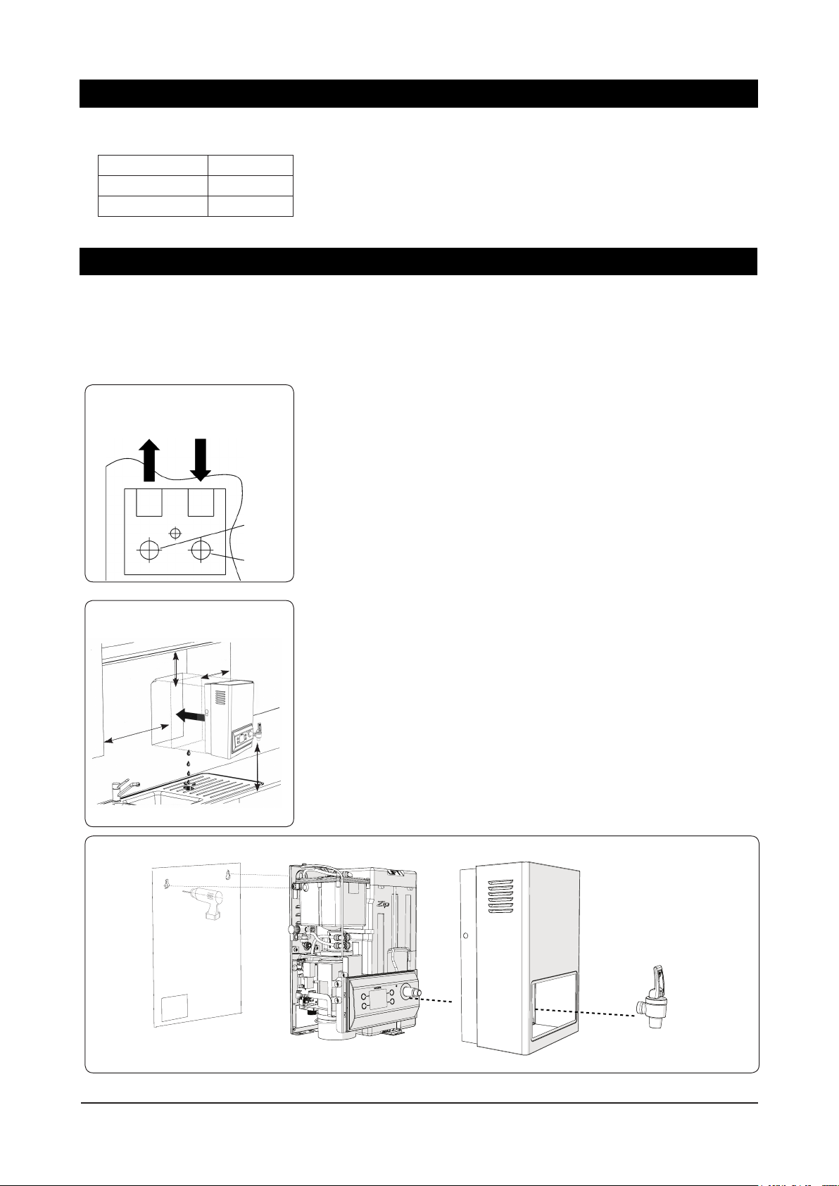
Approximate Weight When Filled
3.0 Litre models 12.5 kg
5.0 Litre models 16.5 kg
7.5 Litre models 20.5 kg
COLD
INLET
100 mm
minimum
clearance
150 mm
VENT
OUTLET
INLET
POSITION
VENT
POSITION
20 mm
minimum
clearance
from right
edge to wall
300 mm
e) Access to drainage from a vent situated at the base of the heater.
f) If the water pressure is likely to exceed 700 kPa, a 350 kPa pressure
reducing valve must be installed in the cold water supply line.
f) In all installation instances the walls of the heater must be vertical and
the base horizontal, there can be no exceptions to this rule.
Installation Procedures
Before You Begin
Refer to the mounting-hole template on page 17.
Read the installation and operating instructions completely.
Decide whether to install with concealed or exposed plumbing and/or
electrical connections. Concealed connections are preferred for superior
appearance.
Step 1 – Positioning
Position the heater so the tap will drain on to a draining board or drip tray.
Position the base of the tap to be not less than 300 mm above the
draining board (height should be increased only if essential for filling larger
vessels).
Provide clearance for service access of not less than 100 mm top, 150 mm
left, 20 mm right.
Mark corner positions for the heater on the wall so as to position the paper
mounting-hole template.
Step 2 – Fastening
Position mounting-hole template on wall and drill holes where shown.
Remove cover fastening screws from heater and lift whole cover off heater.
Remove filter guide as shown in picture above.
Install plumbing and wiring and prepare pipe ends and wiring ends as
shown.
Screw heater chassis to the wall using screws or bolts suited to the wall.
Screws or bolts must be capable of supporting the heater weight when
filled.
Page 4 of 24 804545NZ - BW_AB Small_09.18 v1.02
Page 5

Installation Procedures
1
45 mm
Concealed
Inlet
Concealed
Vent
Warning: If pressure is likely
to exceed 700 kPa, a pressure
limiting valve must be installed
in the cold water supply line.
Zenith recommends a valve
rated at 350 kPa for this application.
2
Remove Filter Guard
Step 3 – Connecting
THE FOLLOWING PROCEDURE IS TO BE DONE BY AN AUTHORISED
INSTALLER ONLY.
3.1 Plumbing
For exposed plumbing connection, connect the cold water inlet pipe from the
base of the heater directly to the 12.7 mm compression fittings.
For concealed plumbing connections, connect the cold water pipe through
the rear of the chassis using a 12.7 mm capillary elbow (# 63 Swivel
Elbows).
Cold water pipes must be flushed before connection to the inlet. Any
clogging due to sediment or fines will adversely affect the operation of the
heater.
It is recommended that the heater be installed with a stop cock which allows
it to be isolated from the mains supply for servicing.
Water pressure requirements:
Minimum - 70 kPa maximum - 700 kPa.
3.2 Venting
A vent at the base of the heater must be plumbed to a safe visible location
as, under certain conditions, it may discharge cold or boiling water and/or
steam.
For exposed vent plumbing, connect vent outlet from the base of heater to
a 12.7 mm pipe which has a continuous fall, is no more than 3 metres long,
has no more than 3 right angle bends, and visibly discharges to a waste
water drain.
Alternatively attach a tundish to the wall as shown and plumb away to
waste.
Vent line
804545NZ - BW_AB Small_09.18 v1.02 Page 5 of 24
Visible Tundish
Note: when routing the plumbing for the vent / tundish installed and mains
inlet line, ensure you do not obstruct filter access for filter replacement.
Page 6

Installation Procedures
3.3 Electrical
Warning: Do not turn on the power until instructed. Water must first be available from the tap
outlet to prevent damage.
This unit is designed for connection to a 220-240 volt AC
power supply via either a concealed electrical connection or
an exposed electrical connection.
For an exposed electrical connection, the pre-fitted flex
and plug cable is plugged into the PCB as shown. Use a
standard 10 amp, 220-240 volt power outlet within 1500
mm from the heater with adequate power for the unit.
For a concealed electrical connection, disconnect the
pre-fitted flex and plug cable at the PCB connector and
discard. Connect the Live (Active) and Neutral wires of the
concealed power cable through the rear access opening to
the green terminal block on the PCB. Crimp a 6.3 mm QC
female spade connector to the earth wire of the concealed
power cable and attach to the chassis earth male terminal.
For a concealed electrical connection, an isolation switch
should be installed.
Check that the earth is connected through the PCB to the
chassis with an ohm meter.
Warning: Do not connect both options. It is essential that the flex and plug cable is removed
from the PCB if the concealed connection is used. Otherwise the GPO plug will become live.
Step 4 – Installing Filter Guide
Assemble the lter guide provided with the unit, make sure it is locked in position, then put the cover back on.
1. Push the lter guide upwards 2. Rotate clockwise until locked
Step 5 – Installing Tap
Thread Tape
1. After the lter guide is installed, t the cover to the
unit and x with screws top and bottom.
Page 6 of 24 804545NZ - BW_AB Small_09.18 v1.02
2. Before installing the tap, ensure sufcient
thread tape is applied to the thread.
Page 7
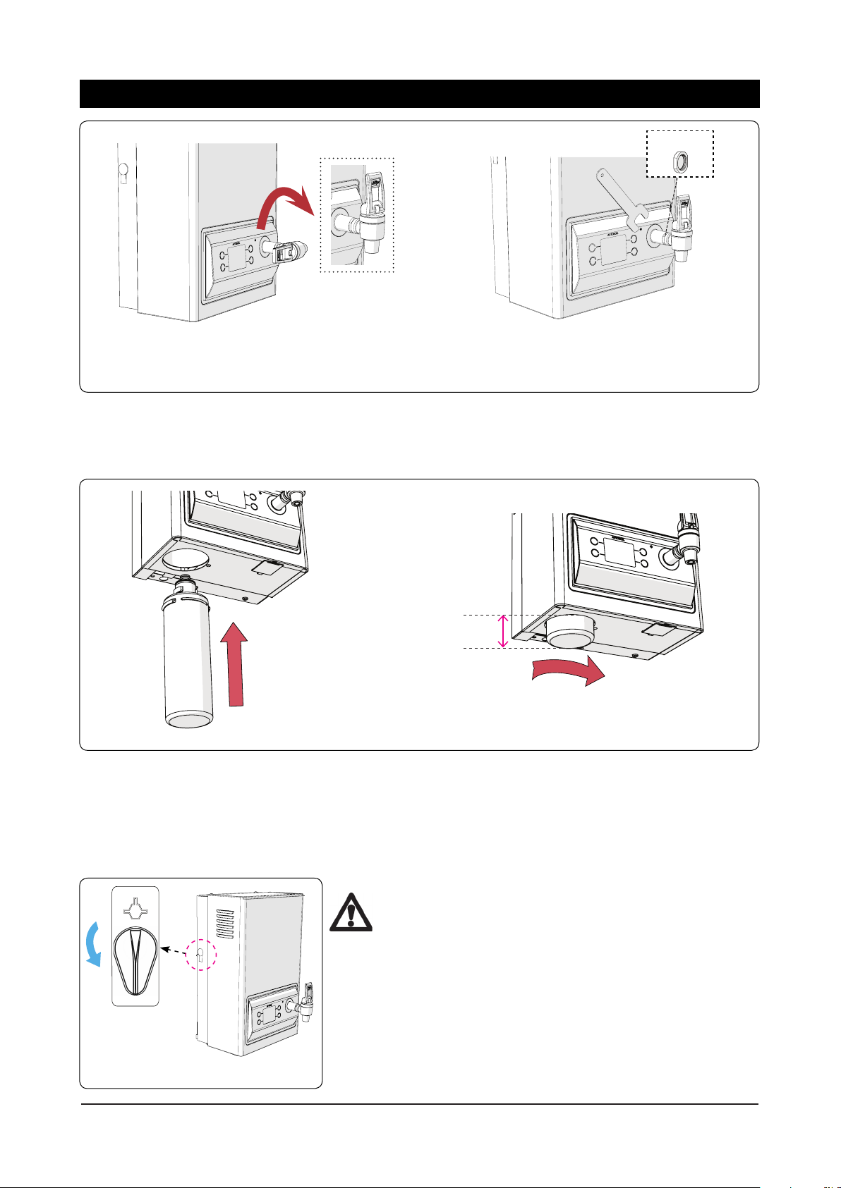
Installation Procedures
FILTER FLUSH
FILTERED
Lock nut
3. After the cover is tted, turn the tap fully clockwise to
the end stop and stopped at upright position.
4. Use the spanner supplied to tighten the lock nut
anti-clockwise.
Step 6 – Installing Filter
To install a lter, insert the lter into the base of the unit as shown and turn 90° until a click or stop point is reached, see
images below. There should be approximately 20mm of the lter protuding when installed.
20mm
1. Insert the lter
2. Turn the lter through 90° until
fully engaged
NOTE: For safe operation, the filter cartridge should be replaced every 6-12 months, or earlier if you notice a
persistent reduction in water pressure from the appliance or an unpleasant taste or odour in the water. Refer to
Filter Replacement section on page 21 for instructions of changing lter.
Step 7 – Commissioning - Filter Flush & Calibrate
Warning: Do not turn on the power until instructed.
Water must first be available from the tap outlet to
prevent damage.
1. The filter flush valve switch is located on the left side of the
unit. Check that it is in the correct position to perform a filter
Rotate lter switch
to FILTER FLUSH
Fig.1
804545NZ - BW_AB Small_09.18 v1.02 Page 7 of 24
flush. Rotate the filter flush switch (either way) to point down
to the “FILTER FLUSH” position, as shown in Fig.1.
2. Turn on the mains water. Allow at least 5 litres of water to
flush through the filter. Make sure there is water flowing from
Page 8

Installation Procedures
FILTER FLUSH
FILTERED
the vent outlet (i.e. the valve setting is correct). Water should not flow
into the tank.
3. Once the filter flush is complete, rotate the filter valve switch 180°
(either way) to point up to the “FILTERED” position (Fig.2).
Rotate switch to
FILTERED
Fig.2
Depress
4. Open the tap (push the lever backwards) into the locked open
position (Fig.2) and allow the tank to fill until water flows from the tap
outlet.
5. Once the water is available from the tap, turn off the mains water and
close the tap outlet.
6. Turn on the power to the unit (water must be in the tank).
7. Touch the white circle next to the left of the [Tick] to “Continue”
Inlet water
15°C 10°C
temp
3.0 Litre models 16 min 17 min
5.0 Litre models 16 min 17 min
7.5 Litre models 23 min 24 min
For screen operation, see the section on “Menu Operation”.
8. Boiling Calibration will commence. It will take several minutes for the
water to boil.
Calibrating Completed
9. When it completes (as prompted), turn on the mains water supply.
10. Select to
Continue
11. The home screen will be shown (see section 2.1).
12. The tank will fill and heat. It will take the initial times shown in the
table to reach the final state.
Page 8 of 24 804545NZ - BW_AB Small_09.18 v1.02
Page 9

1. Understanding Icons and Buttons
Menu Operation
The Autoboil uses a display and button menu system for
setup and operation adjustment.
The display does not have a touch screen feature. The side
buttons are used to navigate, perform selections and modify
values.
The icon changes according to the button action. A button
has no function when no icon is shown.
2. Home Screen Content
Move to the next item able to be highlighted.
Move to the previous item able to be highlighted.
Confirm menu selection.
Move to the previous menu.
Perform one of 3 functions:
1. Move to the menu titled by the highlighted item.
2. Select the currently highlighted item to adjust it.
3. Confirm the value of a selected item.
Increment the item selected.
Decrement the item selected.
2.1 Normal Mode
Button 2 shows faults information.
Button 3 shows more information about the lter life.
Fault Indication:
There are no current faults.
Shown red, there are current faults.
804545NZ - BW_AB Small_09.18 v1.02 Page 9 of 24
Page 10

Menu Operation
Using to navigate to the lter life settings
menu.
Button 4 will show more information about the sleep
mode settings.
Using to navigate to the sleep mode settings
menu.
Filter Indication:
Days remaining of lter life.
Shown red, lter needs replacement.
Sleep Mode Indication:
Unit will enter sleep mode at the time shown.
Unit will enter sleep mode when it is dark.
All sleep saving modes are disabled.
2.2 Sleep Mode
Trigger Indication:
Unit will exit sleep mode at the time shown.
Unit will exit sleep mode when ambient light returns to normal (bright room).
Page 10 of 24 804545NZ - BW_AB Small_09.18 v1.02
Page 11

2.3 Sleep Override Mode
Menu Operation
Awake time remaining:
Unit will return back to sleep mode after this time.
3. Settings Menu
Select on the home screen to navigate to the main menu.
Choose
Settings
and select
Choose an option and select
Main Menu Settings Menu
804545NZ - BW_AB Small_09.18 v1.02 Page 11 of 24
Page 12

Menu Operation
3.1 Settings - Date/Time
From the settings menu choose
and select
Navigating using and
Perform a selection or confirm an adjusted value using
Adjust the date/time values using and
Note: Time can be in 12hr or 24hr mode.
To set up time choose a selection, then
Settings
3.3 Settings - Sleep Modes
From the settings menu choose
and select
Sleep Modes
3.3.1 Sleep Trigger
Choose
Conrm using and return to the previous menu.
Sleep Trigger
to select the trigger for the unit to enter its sleep mode.
and select , and
Adjust value by using and then to conrm.
Follow similar steps to set up date.
3.2 Settings - Temperature
From the settings menu choose
select and to adjust boiling point.
Confirm using and return to the previous menu.
Note: Setting the temperature above 98°C may require
boiling calibration to prevent excessive steam release
or high energy usage (see section 4.2).
Settings
and
Disabled
Timer
Ambient Light
the unit will not enter its sleep mode.
the unit will use the on/off timer settings to enter and exit its sleep mode.
the unit will enter its sleep mode when
darkness is detected and will exit its
sleep mode when the ambient light
returns to a normal level (bright room).
3.3.2 Sleep Action
Choose
to select the heating mode action when the unit is in its
sleep mode. Conrm using and return to the previous
menu.
Sleep Action
and select and
Page 12 of 24 804545NZ - BW_AB Small_09.18 v1.02
Page 13

Menu Operation
68°C
While the unit is in its sleep mode the
set point of the water will be reduced
to 68°C.
Off
While the unit is in its sleep mode no
heating of the water will occur.
3.3.3 Timer Settings
Choose
Conrm using and return to the previous menu.
Timer Settings
and select and
to select the trigger for the unit to enter its sleep mode.
► Saving changes
to exit the timer settings menu. A confirmation menu will
be shown.
Choose
confirm. Choose
Continue
to save changes and to
Cancel
to discard changes
and to confirm.
3.4 Settings - Filter
Everyday
Adjust on/off timer settings for all 7 days
simultaneously.
Weekdays
Adjust on/off timer settings for all 5
weekdays simultaneously.
Weekends
Adjust on/off timer settings for the 2
weekend days simultaneously.
Adjust on/off timer settings for the 7
Individual Days
days separately.
►Individual Days Settings
Choose item and adjust value, then to confirm.
From the settings menu choose
Filter
and select
3.4.1 Internal / External Filters
Choose
Internal
or
and select
Choose one of the following options and select
External
Note: There is a similar set of menus for both internal
and external lters.
804545NZ - BW_AB Small_09.18 v1.02 Page 13 of 24
Page 14

Menu Operation
3.4.2 Filter Life / Usage
This allows modication of lter life and usage parameters.
Filter Life – Options are:
► Disabled (no lter replacement reminder will be shown on
home screen)
► 1-14 months (Default 12 months)
Filter Usage – Automatically increments daily. This is reset to
“0 Days” when a lter reset is performed. Can be adjusted if a
partially used lter is inserted.
The days remaining of the lter shown on this menu and on
the home screen are based on these 2 parameters.
Choose
the lter usage counter.
Continue
and select to reset
3.4.2 Filter Log
The log shows the dates that the lter usage counter was reset
and the “days used” before the reset was performed.
Use and to scroll through the log history.
3.4.3 Replace Filter
This action will reset the lter usage counter. A reminder is
shown to ush the new lter before doing this (see page 21 -
Filter Replacement).
Select to continue after ushing.
4. Install Menu
Select on the home screen to navigate to the main menu.
Choose
Install
and select
Page 14 of 24 804545NZ - BW_AB Small_09.18 v1.02
Page 15

4.1 Install - Light Calibration
Menu Operation
From the install menu choose
select
Before continuing ensure the unit is in its normal typical light
environment and the front panel is not covered.
Select to perform the calibration. It will complete after 6
seconds.
Continue
and
The unit will heat the water for boiling calibration. This
may take several minutes depending on the initial water
temperature. When it completes the screen will automatically
return to the install screen.
4.3 Install - Power Cycle
From the install menu choose
select
This will turn the unit briey off then on (restart). All custom
settings will be retained.
Choose
the power cycle.
Continue
Power Cycle
and select to perform
and
Select to continue.
4.2 Install - Boiling Calibration
This automatically corrects for boiling point differences at
each installation site. The unit was calibrated by the installer
at installation; however the installation environment may have
changed requiring recalibration of the boiling point.
Incorrect boiling calibration points may cause excessive
steam vent releases, or increased energy usage.
Boiling calibration is recommended when the temperature
setting is close to 100°C (section 3.2).
From the install menu choose
select
Continue
and
804545NZ - BW_AB Small_09.18 v1.02 Page 15 of 24
Page 16

Menu Operation
5. Info Menu
Select on the home screen to navigate to the main menu.
Choose
Info
and select
5.2 Info - Current Fault
From the info menu choose
Current Fault
6. Service Menu
Note: The service menu is used by technicians only for
diagnostic purposes.
Choose value then select
5.1 Info - Product
From the install menu choose
Product
Page 16 of 24 804545NZ - BW_AB Small_09.18 v1.02
Page 17

Wall Mounting Template Dimensions
250 (7.5L)
52 (7.5L)
250 (5L)
52 (5L)
37 (3L)
235 (3L)
37 (1.5L)
235 (1.5L)
561 (7.5L)
448 (5L)
414 (3L)
329 (1.5L)
70
40
25
37
55
56
Cold
Inlet
76
Positioning pin
Vent
External Plumbing
Electrical Wiring
Internal Plumbing
273 (1.5L & 3L)
302 (5L & 7.5L)
542 (7.5L)
429 (5L)
395 (3L)
310 (1.5L)
804545NZ - BW_AB Small_09.18 v1.02 Page 17 of 24
Page 18

Spare Parts
Item Kit Number Description
EB & AB 3 Ltr Tank Assy
EB & AB 5 Ltr Tank Assy
EB & AB 7.5 Ltr Tank Assy
AB Fascia & PCB assy
AB Fascia & PCB assy Grey
Escutcheon
Tap Lock Nut
Tap Top Assy
Flow Insert
Tap Body
Hot Tank NTC
Loom, PCB to Overload
Ribbon Cable
Plug, HB Outlet
PCB, AB Powerboard
0.2 mic Zenith MicroPurity Filter 2 size
Cistern Tank
Ball Valve assy
Cistern Gasket
Cistern Lid EB & AB
Elbow Stem 1/4"
Grommet, Cistern to Tank
Overload
Side release plug
Seal transfer tube
10
12
13
14
15
16
17
18
19
20
21
22
94443NZ
1
2
3
4
5
6
7
8
9
11
94444NZ
94445NZ
94479NZ
94480NZ
94447NZ
94448NZ
90501NZ
93730NZ
94478NZ
91440NZ
94449NZ
94481NZ
94451NZ
94482NZ
93704NZ
94454NZ
94455NZ
94456NZ
94457NZ
93118NZ
90100NZ
94458NZ
94459NZ
94460NZ
Item Kit Number Description
23
24
25
26
27
28
29
30
31
32
33
34
35
36
38
39
40
94483NZ
94461NZ
90485NZ
90486NZ
94484NZ
94485NZ
94486NZ
94487NZ
94488NZ
94489NZ
94470NZ
90493NZ
90494NZ
94471NZ
94472NZ
90506NZ
94473NZ
94474NZ
94490NZ
94491NZ
94492NZ
94493NZ
94494NZ
94495NZ
Metering Tube 1.5 & 3 Ltr
Metering Tube 5 & 7.5 Ltr
Element assy 1500W 1.5 & 3
Element assy 2400W 5 & 7.5
Bush Vent assy 3 ltr
Bush Vent assy 5 ltr
Bush Vent assy 7.5 ltr
Inlet assy
AB Fascia Kit
AB Fascia Kit Grey
Tap assy
Metering tube kit 1.5 & 3 Ltr
Metering tube kit 5 & 7.5 Ltr
Cistern Gasket kit
Cistern assy
Tap Outlet
Hot Tank Gasket kit 1.5 & 3 Ltr
Hot Tank Gasket kit 5 & 7.5 Ltr
PCB Splash Guard
Filter Flush Valve
Filter Head Kit (no Bracket)
PCB & Filter Bracket
Filter Guide
Grommet
Page 18 of 24 804545NZ - BW_AB Small_09.18 v1.02
Page 19

Exploded View Diagram
18
17 20
31
36
21
35
16
40
15
14
12
34
19
29
26
30
2322
9
25
24
33
1
38
39
32
11
13
10
7 6 5
28
8
234
27
804545NZ - BW_AB Small_09.18 v1.02 Page 19 of 24
Page 20

Problem Solving
Symptom Possible Cause Solution
Fails to dispense water.
Water not boiling.
Runs out of boiling water and
fails to refill.
Outlet tap drips.
Overflow from vent.
Excessive steam from vent.
Power “on” but no heat.
Overload repeatedly tripping with
excessive steam.
Overload repeatedly tripping
without
excessive steam.
Sleep/Wakes incorrectly when
room is light/dark.
Incorrect filter flush valve setting.
Incorrect filter insertion.
Water isolating valve turned off.
Blocked filter, blocked meter tube,
blocked strainer, jammed ball
valve assembly.
Incorrect temperature setting.
Incorrect sleep mode setting.
No power.
Faulty thermostat, faulty element,
faulty cutout.
Requires boiling calibration.
Incorrect filter flush valve setting.
Incorrect filter insertion.
Internal adjustment.
Requires light calibration.
Incorrect sleep modes settings.
Check filter flush valve position
(see Step 7, page 8).
Check filter is inserted correctly
(see page 21).
Check water supply valve.
Contact Zenith authorised agent.
Check temperature setting
(see section 3.2).
Check sleep mode settings (see section
3.3) or reset settings from service menu.
Check power supply.
Contact Zenith authorised agent.
Perform boiling calibration
(see section 4.2).
Check filter flush valve position
(see Step 7, page 8).
Check filter is inserted correctly
(see page 21).
Contact Zenith authorised agent.
Perform light calibration
(see section 4.1).
Check sleep mode settings (see section
3.3) or reset settings from service menu.
Page 20 of 24 804545NZ - BW_AB Small_09.18 v1.02
Page 21

Earthing Continuity Verification
If required, an earth continuity test
can be performed by testing between
the earth pin on the products lead
and a exposed piece of metal on the
case and the tap body.
Warning: this appliance must be earthed.
Following remedial service the earthing continuity of the heater must be
checked by a qualified technician using an appliance tester, or continuity
tester of accuracy Class 5 or better. Class 5 denotes an accuracy of 5% full
scale deflection.
1. Isolate power supply.
2. Set meter to 0 ohm with leads connected together.
3. Connect one test lead to the earth pin on the three pin plug.
4. Connect the other test lead to a bare patch of metal (preferably on the
edge) of the top of the cover, then to the front cover of the unit, and then to
the tap.
Warning- the water may be boiling - show extra care.
5. Test that in every instance the electrical resistance does not exceed 1
ohm.
Operating Procedures
Tap Operation
Boiling water
Zenith Autoboil is fitted with a two-way tap for filtered instant boiling
water.
For instant boiling water, gently pull the top of the tap forward.
Boiling water will flow until the tap handle is released.
This operation gives fingertip flow control for safe filling of cups and
mugs.
To fill larger vessels such as teapots and saucepans, rotate the tap
180 degrees and depress it until it locks into a horizontal position.
Boiling water will flow until the tap is returned to its normal vertical
position. This operation allows the vessel to be filled without
holding your hand where it may be affected by steam.
804545NZ - BW_AB Small_09.18 v1.02 Page 21 of 24
Page 22

Filter Replacement
NOTE: For safe operation, the filter cartridge should
be replaced every 6-12 months, or earlier if you notice
a persistent reduction in water pressure from the
appliance or an unpleasant taste or odour in the water.
To Replace Filter:
• Turn the filter anti-clockwise (Fig.1) and pull the cartridge down
(Fig.2). Have an absorbent cloth ready as a small amount of
water will be released as the filter is removed. The cartridge
should release from the filter head.
1. Turn the lter anti-clockwise.
Fig.1
Fig.2
2. Remove the
lter by gently
pulling down.
• Replace with a new filter by gently pushing up, engaging the
key and turning the filter clockwise until the filter clicks or
locks into place.
• Perform filter flush by following the steps 1 - 4 only on pages
7-8 (Step 7 - Commissioning).
• Go to [Replace Fitler] screen to reset the lter usage counter.
Follow the instructions on page 14 (3.4.3 Replace Filter)
section for details of menu operation.
Warning! Not changing filtration cartridges when
required may cause the water to become biologically
unsafe.
If the Zenith Autoboil is switched off for a long period of time (e.g.
more than a weekend), run water through the outlet for at least 5
minutes before consumption.
Use only Zenith Filters in this product to ensure effective filtration
and operation. Replacement filter cartridges can be obtained
through plumbing suppliers or directly from Zenith.
Filter replacement instructions are included with the filter cartridge
spare part kits.
Please dispose of the filter cartridge responsibly.
Page 22 of 24 804545NZ - BW_AB Small_09.18 v1.02
Page 23

Cleaning
Cleaning Case
Do not use strong, corrosive, spray or abrasive cleaners. Clean the
case with a soft cloth or sponge and mild soapy water.
End of life disposal
In order to help preserve our environment we ask that you dispose
of this product correctly. Please contact your local city council for
collection centre details.
804545NZ - BW_AB Small_09.18 v1.02 Page 23 of 24
Page 24

Contact Details
New Zealand Head Office
Zenith Heaters Limited
IRD/GST No. 95 640 729
Unit 2/15 Moselle Avenue
Henderson
Auckland 0610
New Zealand
www.zenithwater.co.nz
Telephone +(64 9) 838 8612
Free Call 0800 558 055
As Zenith’s policy is one of continuous product improvement, changes to
specifications may be made without prior notice. Images in this booklet have been
modified and may not be true representations of the finished goods.
The standard cup referred to in this publication is 167 ml (6 fl oz).
The standard glass is 200 ml (7 fl oz).
The terms “Zenith” “Hydroboil”, “Autoboil”,” Econoboil”, “Power-Pulse”, “GlobalPlus”,
“MicroPurity” are trademarks of Zip Heaters (Aust) Pty Ltd.
Products described in this publication are manufactured under one or more patents
and further patent applications are pending.
One or more products described in this publication are also registered designs of
Zip Heaters (Aust) Pty Ltd.
Please check the website for the latest user manual
www.zenithwater.co.nz
© 2018 Zenith Heaters Ltd. All Rights Reserved.
Page 24 of 24 804545NZ - BW_AB Small_09.18 v1.02
 Loading...